US11110824B2 - Guide device for guiding an adjustment movement of a vehicle seat - Google Patents
Guide device for guiding an adjustment movement of a vehicle seat Download PDFInfo
- Publication number
- US11110824B2 US11110824B2 US16/797,413 US202016797413A US11110824B2 US 11110824 B2 US11110824 B2 US 11110824B2 US 202016797413 A US202016797413 A US 202016797413A US 11110824 B2 US11110824 B2 US 11110824B2
- Authority
- US
- United States
- Prior art keywords
- component
- section
- guide
- slide rail
- rail device
- Prior art date
- Legal status (The legal status is an assumption and is not a legal conclusion. Google has not performed a legal analysis and makes no representation as to the accuracy of the status listed.)
- Active
Links
- 238000009434 installation Methods 0.000 claims description 29
- 238000006073 displacement reaction Methods 0.000 description 9
- 238000004519 manufacturing process Methods 0.000 description 8
- 230000003993 interaction Effects 0.000 description 4
- 239000002184 metal Substances 0.000 description 4
- 239000011324 bead Substances 0.000 description 2
- 230000008901 benefit Effects 0.000 description 2
- 239000011248 coating agent Substances 0.000 description 2
- 238000000576 coating method Methods 0.000 description 2
- 238000005246 galvanizing Methods 0.000 description 2
- 210000002816 gill Anatomy 0.000 description 2
- 238000003780 insertion Methods 0.000 description 2
- 230000037431 insertion Effects 0.000 description 2
- 238000000034 method Methods 0.000 description 2
- 239000000843 powder Substances 0.000 description 2
- 230000015572 biosynthetic process Effects 0.000 description 1
- 238000010276 construction Methods 0.000 description 1
- 210000003127 knee Anatomy 0.000 description 1
- 210000002414 leg Anatomy 0.000 description 1
- 235000013372 meat Nutrition 0.000 description 1
Images


Classifications
-
- B—PERFORMING OPERATIONS; TRANSPORTING
- B60—VEHICLES IN GENERAL
- B60N—SEATS SPECIALLY ADAPTED FOR VEHICLES; VEHICLE PASSENGER ACCOMMODATION NOT OTHERWISE PROVIDED FOR
- B60N2/00—Seats specially adapted for vehicles; Arrangement or mounting of seats in vehicles
- B60N2/02—Seats specially adapted for vehicles; Arrangement or mounting of seats in vehicles the seat or part thereof being movable, e.g. adjustable
- B60N2/04—Seats specially adapted for vehicles; Arrangement or mounting of seats in vehicles the seat or part thereof being movable, e.g. adjustable the whole seat being movable
- B60N2/06—Seats specially adapted for vehicles; Arrangement or mounting of seats in vehicles the seat or part thereof being movable, e.g. adjustable the whole seat being movable slidable
- B60N2/07—Slide construction
- B60N2/0702—Slide construction characterised by its cross-section
- B60N2/0705—Slide construction characterised by its cross-section omega-shaped
-
- B—PERFORMING OPERATIONS; TRANSPORTING
- B60—VEHICLES IN GENERAL
- B60N—SEATS SPECIALLY ADAPTED FOR VEHICLES; VEHICLE PASSENGER ACCOMMODATION NOT OTHERWISE PROVIDED FOR
- B60N2/00—Seats specially adapted for vehicles; Arrangement or mounting of seats in vehicles
- B60N2/02—Seats specially adapted for vehicles; Arrangement or mounting of seats in vehicles the seat or part thereof being movable, e.g. adjustable
- B60N2/04—Seats specially adapted for vehicles; Arrangement or mounting of seats in vehicles the seat or part thereof being movable, e.g. adjustable the whole seat being movable
- B60N2/06—Seats specially adapted for vehicles; Arrangement or mounting of seats in vehicles the seat or part thereof being movable, e.g. adjustable the whole seat being movable slidable
- B60N2/08—Seats specially adapted for vehicles; Arrangement or mounting of seats in vehicles the seat or part thereof being movable, e.g. adjustable the whole seat being movable slidable characterised by the locking device
-
- B—PERFORMING OPERATIONS; TRANSPORTING
- B60—VEHICLES IN GENERAL
- B60N—SEATS SPECIALLY ADAPTED FOR VEHICLES; VEHICLE PASSENGER ACCOMMODATION NOT OTHERWISE PROVIDED FOR
- B60N2/00—Seats specially adapted for vehicles; Arrangement or mounting of seats in vehicles
- B60N2/02—Seats specially adapted for vehicles; Arrangement or mounting of seats in vehicles the seat or part thereof being movable, e.g. adjustable
- B60N2/04—Seats specially adapted for vehicles; Arrangement or mounting of seats in vehicles the seat or part thereof being movable, e.g. adjustable the whole seat being movable
- B60N2/06—Seats specially adapted for vehicles; Arrangement or mounting of seats in vehicles the seat or part thereof being movable, e.g. adjustable the whole seat being movable slidable
- B60N2/07—Slide construction
- B60N2/0722—Constructive details
- B60N2/0727—Stop members for limiting sliding movement
Definitions
- the invention relates to a guide device for guiding an adjustment movement of a vehicle seat according to the preamble of claim 1 .
- this adjustment movement constitutes the displacement of elements which are mounted on plain bearings or ball bearings relative to one another by means of rail devices, that is to say, for example, an upper seat part relative to a lower seat part, an upper armrest part relative to a lower armrest part or a headrest part relative to a backrest.
- These guide devices offer the user of a vehicle seat the possibility of adapting the position of the displaceable part or of the entire seat depending on the size of the user, on the ratio of the leg length to the torso length and on his personal comfort, by displacing the part or the seat, starting from a basic position, in a first direction, for example forwards, or in a second direction which is preferably opposite to the first direction, that is to say for example backwards, and locking it in an adapted position.
- Corresponding locking devices are known from the prior art and are therefore not explained in detail in the scope of the present invention.
- Known rail devices have a guide rail device and a slide rail device which is adjustable with respect thereto.
- a first standard stop element of the guide rail device forms a mechanical interaction with a first standard stop element of the slide rail device, so that a further displacement in this direction is not possible.
- a second standard stop element of the guide rail device forms a mechanical interaction with a second standard stop element of the slide rail device, so that a further displacement in this direction is likewise not possible.
- a vehicle seat can be positioned so far forward in the vehicle by a maximum adjustment forwards that a very tall driver hits his knees on the steering wheel.
- components of such a vehicle seat can collide with one or more windows of the vehicle in the event of a maximum adjustment towards the rear. This is possible in particular if the driver's cab of this vehicle is very narrow, such as a driver's cab of an excavator.
- a guide device for guiding an adjustment movement of a vehicle seat comprising a guide rail device and a slide rail device arranged displaceably thereto in a longitudinal adjustment direction of the guide device, the slide rail device having a first stop element and a second stop element.
- a one-piece component which is divided into a first and a second section in the longitudinal direction of the guide device, is arranged between the slide rail device and the guide rail device, the component being fixedly connected to the guide rail device by means of at least one connection element arranged in the first section.
- the second section of the component forms a first stop element for one of the stop elements of the slide rail device at a first end and a second stop element for the other stop element of the slide rail device at a second end.
- the guide rail device and the associated slide rail device are preferably ball rail devices in the sense of linear rails mounted on ball bearings with respect to one another, so that a ball rail guide unit is provided overall.
- This embodiment is particularly suitable for a low-friction relative movement of the two rails.
- the rest of the guide device is preferably already a complete assembly and/or fully functional with respect to the relative movement of the two rail devices even without a component inserted.
- the component is preferably not designed as part of the guide rail device and/or the slide rail device, but preferably independently thereof.
- the arranged component ensures, on the one hand, that slide rail devices and guide rail devices installed as standard can continue to be used for the guide device.
- the component can advantageously be retrofitted, so that a quick and inexpensive solution for changing the limitation of the adjustment paths can be provided in particular when a change of driver is imminent or the customer requirements are still changing afterwards.
- the component can be retrofitted into the rest of the already pre-assembled guide device.
- the component is preferably designed such that to insert the component (“threading”) into the guide device, the component only undergoes translation in the longitudinal direction of the guide device and rotation about an axis in the width direction of the guide device.
- stop elements of the slide rail device advantageously do not constitute the standard stop elements which, in conjunction with the stop elements of the guide rail device, are responsible for limiting the adjustment paths without an insertable component.
- the interacting stop elements of the slide rail device and guide rail device are designated as “standard stop elements”.
- the interacting stop elements of the slide rail device and the component are referred to as “stop elements”.
- the stop elements of the slide rail device which can interact with the stop elements of the component are also advantageously part of the standard guide device and, for example, designed as part of screw connections.
- the screw connections are advantageously provided for connecting the slide rail device to an upper part to be displaced.
- the standard stop elements of the slide rail device and of the guide rail device are arranged such that they are arranged centrally or on both sides symmetrically with respect to the central axis of the guide device in the width direction of the guide device. This ensures that the rail devices cannot easily tilt when the standard stop elements are attached. At the same time, safe and mechanically stable guidance and limitation of the adjustment paths should be assumed.
- the arrangement of the standard stop elements ensures that only the same standard stop elements can interact with one another.
- the guide device is now considered without an insertable component. It is therefore ruled out, for example, that a standard stop element of the guide rail device which is responsible for limiting the adjustment path in the first direction interacts with a standard stop element of the slide rail device which is responsible for limiting the adjustment path in the second direction. The same naturally applies to the reverse case. All standard stop elements belonging to the guide device are therefore preferably arranged one behind the other, as seen in the longitudinal direction of the guide device.
- the standard stop elements of the guide rail device which limit the adjustment path in the first direction are arranged in a first end region of the guide rail device, whereas, for example, the standard stop elements which limit the adjustment path in the second direction are arranged in a second end region of the guide rail device.
- the standard stop elements of the slide rail device which limit the adjustment path in the first direction are arranged in a first central region, whereas, for example, the standard stop elements which limit the adjustment path in the second direction are arranged in a second central region.
- the standard stop elements belonging to the guide rail device from the first end region can interact with the standard stop elements belonging to the slide rail device from the first central region.
- the standard stop elements belonging to the guide rail device from the second end region can interact with the standard stop elements belonging to the slide rail device from the second middle region; at least when no component according to claim 1 is used.
- the component arranged thus takes over the limitation of the adjustment path in the first direction and at the same time in the second direction.
- it can be mechanically securely installed in the guide rail via the connection element in the first section, which is designed as part of the component, for example as a recess in the component and preferably as a through hole.
- the stop elements of the slide rail device are preferably designed as mechanical stop elements which are arranged so as to protrude into an installation space which is preferably designed as an intermediate space between a slide rail element of the slide rail device and a guide rail element of the guide rail device.
- the component preferably comprises precisely one first section and precisely one second section.
- the component is preferably otherwise free of further sections.
- the component has exactly one mirror symmetry plane, which is preferably arranged parallel to the longitudinal direction of the guide device.
- the component is therefore simply designed; it can be installed intuitively within the guide device, since the arrangement of the plane of mirror symmetry in relation to the longitudinal direction of the guide device is self-explanatory.
- the mirror symmetry plane and its arrangement parallel to the longitudinal direction of the guide device ensure that there are two possible ways of installing the component. These two options and the resulting installation states are explained in more detail below.
- a longitudinal direction of the component is preferably arranged parallel to the longitudinal direction of the guide device in at least one, preferably in both of its states installed in the guide device. The same preferably applies to a width direction of the component in relation to the width direction of the guide device and to a height direction of the component in relation to the height direction of the guide device.
- the component is preferably arranged centrally with respect to a width direction of the guide device, so that it is arranged centrally relative to the width of the guide rail device, the guide rail element, the slide rail device and/or the slide rail element.
- the component as a whole has a simple design.
- the component has a homogeneous thickness over its entire length and/or width. Provision can also be made for the first section of the component to be linear when viewed in the longitudinal direction.
- the second section of the component which is preferably arranged directly adjacent to the first section, has a U shape.
- This U shape is preferably designed with respect to the longitudinal direction of the component.
- the length of the component preferably extends in the longitudinal direction of the component.
- the width of the component preferably extends in the width direction of the component.
- the thickness of the component preferably extends at least in sections in the vertical direction of the component.
- U shape is understood to mean that the element, in this case the second section, has a central linear portion and that two portions perpendicular to it are arranged directly adjacent to the central portion.
- the second section may optionally have rounded sections which form the corners of the U shape and/or the connection point to the first section.
- a vertical portion or a rounded portion or a vertical portion together with a rounded portion each preferably form a stop element of the second section of the component.
- the component can in particular be designed as a sheet metal part, the manufacture of which in terms of shape only comprises the production of the blank from a metal sheet and the folding of the blank. Afterwards, surface-treating or finishing steps such as galvanizing or powder coating are possible.
- the component therefore preferably only has tabs which are folded relative to one another (“folds”), preferably only four, as production elements.
- the component is therefore preferably free of further production elements such as folds, envelopes, standing seams, beads, gills, threaded bores, weld seams and/or deep-drawn bodies.
- the longitudinal adjustment direction of the guide device is a direction towards the front and/or a direction towards the rear.
- the first section of the component is arranged in front of the second section.
- the first section of the component is arranged behind the second section.
- front and “rear” represent directions which relate to the guide device. These directions can also correspond to the directions of the entire seat or an upper part of the seat, but do not have to.
- the component can thus have two orientations with respect to the longitudinal adjustment direction of the guide device, which are rotated by 180° with respect to one another.
- the orientations relative to one another are preferably rotated through 180° with respect to an axis in the height direction of the guide device.
- the relative position of the second section of the component with respect to the rest of the guide device and thus to the stop elements preferably differs from the first to the second installation state.
- the position of the component can be adjusted again at least in stages, in order to realise further adjustment possibilities.
- the component has at least one, preferably a plurality of recesses in the first section, wherein it can be connected to at least one fastening element of the guide rail device by means of at least one of the recesses.
- these recesses are arranged in succession in the longitudinal direction of the component. The distance between the recesses can in each case be identical or different.
- the component can preferably be installed in the guide rail device in accordance with both installation states, wherein it is possible to choose between one or more, preferably between all, recesses of the component per installation state for the formation of the connection element to the guide rail device.
- the position of the component is infinitely adjustable in each installation state.
- at least one of the recesses is designed as an elongated hole.
- the component is preferably otherwise free of further recesses. This increases the stability of the component.
- the width of the component is preferably designed such that it does not change over its length and/or height or only changes in the first section.
- the component in the first section has a tapering width oriented towards the second section.
- the recess or the recesses is/are preferably arranged in a wider part of the first section and/or not in the narrower part of the first section.
- the component has a homogeneous width in the second section. Furthermore, it may be advantageous if the component in the second section has an end section which widens relative to the remaining width of the second section. This increases the stability of the component.
- the component is designed to make direct contact with a guide rail element of the guide rail device and/or to be spaced apart from a slide rail element of the slide rail device.
- the stop elements of the slide rail device are the only elements of the guide device with which the stop elements of the component can interact when the slide rail device is adjusted relative to the guide rail device.
- Such a guide device could be arranged on a vehicle seat and/or within a vehicle, for example, such that the longitudinal adjustment direction of the guide device can be arranged parallel to a longitudinal direction of the vehicle seat and/or the lower part of the vehicle seat, and that the guide rail device is fixedly connected to the lower part of the vehicle seat and the slide rail device is fixedly connected to an upper part of the vehicle seat.
- FIG. 1 a - c show schematically several views of a component for insertion in a guide device according to a first embodiment
- FIG. 1 d shows schematically a view of a guide device according to the invention with inserted component
- FIG. 2 a - c shows different stages of an assembly process of the component from FIG. 1 a in a guide device, so that the component is assembled in accordance with a first installation state;
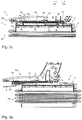
- FIG. 3 a - c show different stages of an assembly process of the component from FIG. 1 a in a guide device, so that the component is assembled according to a second installation state;
- FIG. 4 a shows an oblique view of the assembly of FIG. 2 c
- FIG. 4 b shows an oblique view of the assembly of FIG. 3 c
- FIG. 5 a shows a front view of parts of a vehicle seat with a guide device according to the invention
- FIG. 5 b shows an enlarged view of FIG. 5 a.
- FIGS. 4 a and 4 b show only a lower part SU of a vehicle seat S and FIG. 5 a does not show the entire vehicle seat S, but only parts thereof.
- FIG. 1 d shows only parts of the guide device 1 and in particular not the guide rail device 2 of the guide device 1 .
- the invention is described below on the basis of a guide device 1 for guiding an adjustment movement of a vehicle seat S, wherein the adjustment movement represents, for example, the displacement of an upper seat part SO relative to a lower seat part SU.
- the upper seat part SO is fixedly connected to the slide rail device 3 and the lower seat part SU is connected fixedly to the guide rail device 2 .
- Parts of a vehicle seat S are shown, for example, with reference to FIGS. 2 a - c , 3 a - c and 5 a , 5 b , wherein a guide device 1 is shown with the guide rail device 2 and the slide rail device 3 which can be adjusted for this purpose.
- a co-ordinate system in FIG. 5 a illustrates the orientation of the longitudinal direction 1 xa of the guide device 1 towards the front, the width direction 1 y of the guide device 1 towards the right and the height direction 1 z of the guide device 1 towards the top.
- the guide device 1 is arranged within the vehicle seat S such that the longitudinal direction 1 xa of the guide device 1 corresponds to the seat longitudinal direction Sx, the width direction 1 y of the guide device 1 corresponds to the seat width direction Sy and the height direction 1 z corresponds to the seat height direction Sz.
- the slide rail device 3 is arranged in a basic position, according to which the slide rail device 3 and the guide rail device 2 are not displaced relative to one another.
- end faces of the slide rail element 30 and the guide rail element 20 which are oriented identically are arranged at the same position with respect to the longitudinal direction 1 x of the guide device 1 .
- FIG. 5 b shows an enlargement of a section A′ according to FIG. 5 a.
- a first standard stop element 7 a of the guide rail device 2 forms a mechanical interaction with a first standard stop element 8 a of the slide rail device 3 , so that a further displacement in this direction 1 xa is not possible. This case applies if no component 5 is inserted into the guide device 1 .
- a second standard stop element 7 b of the guide rail device 2 forms a mechanical interaction with a second standard stop element 8 b of the slide rail device 3 , so that a further displacement in this direction 1 xb is likewise not possible.
- the standard stop elements 7 a , 7 b , 8 a , 8 b are each configured as “lugs”, that is to say as folded tabs of a guide rail element 20 of the guide rail device 2 and of a slide rail element 30 of the slide rail device 3 . This case also applies if no component 5 is inserted into the guide device 1 .
- a guide device 1 for guiding an adjustment movement of a vehicle seat S, comprising a guide rail device 2 and a slide rail device 3 arranged displaceably in a longitudinal adjustment direction 1 x of the guide device 1 , wherein the slide rail device 3 comprises a first stop element 4 a and a second stop element 4 b .
- a one-piece component 5 is arranged between the slide rail device 3 and the guide rail device 2 , and is subdivided in the longitudinal direction 1 x of the guide device 1 , which in the present case corresponds to the longitudinal direction of the component 5 , into a first section 51 and a second section 52 .
- the component 5 is fixedly connected to the guide rail device 2 by means of a connection element 53 arranged in the first section 51 , in the present case by means of the fastening element 6 b of the guide rail device 2 .
- the second section 52 of the component 5 forms a first stop element 54 for the first stop element 4 a of the slide rail device 3 at a first end 52 a and a second stop element 55 for the second stop element 4 b of the slide rail device 3 at a second end 52 b .
- the second section 52 of the component 5 forms a first stop element 54 for the second stop element 4 b of the slide rail device 3 at the first end 52 a and a second stop element 55 for the first stop element 4 a of the slide rail device 3 at a second end 52 b.
- the component 5 is not designed as part of the guide rail device 2 and/or the slide rail device 3 , but independently of it.
- FIG. 1 d a view of the guide device 1 from below, that is to say parallel to the height direction 1 z , is shown, the guide rail device 2 being hidden for better clarity.
- the component 5 is arranged centrally with respect to a width direction 1 y of the guide device 1 , so that it is arranged centrally with respect to the width of the guide rail device 2 , the guide rail element 20 , the slide rail device 3 and the slide rail element 30 .
- the component 5 is designed such that for insertion of the component 5 (“threading”) into the guide device 1 , the component 5 only undergoes a translation in the longitudinal direction 1 x of the guide device 1 and a rotation about an axis in the width direction 1 y of the guide device 1 .
- FIG. 2 a - c show different steps in chronological order of threading the component 5 into the rest of the guide device 1 , so that the component 5 is installed according to a first installation state A.
- FIG. 2 a a first step of threading can be seen. Accordingly, the slide rail device 3 and with it the upper seat part SO is displaced to a maximum extent relative to the guide rail device 2 and the lower seat part SU towards the rear 1 xb . This ensures that the rear stop element 4 b of the slide rail device 3 does not collide with the component 5 when threading the component 5 .
- the component 5 is now pushed from the rear seat side in the longitudinal direction towards the front 1 xa with the second section 52 first into the installation space 9 .
- FIG. 2 b the component 5 has already reached its intended position within the rest of the guide device 1 .
- the slide rail device 3 is now moved forwards 1 xa to a maximum extent so that the access to the fastening element 6 b of the guide rail device 2 necessary for fastening the component 5 within the remainder of the guide device 1 is ensured.
- the component 5 is fastened to the lower seat part SU via the guide rail device 2 by means of the fastening element 6 b and the connection element 53 .
- FIG. 2 c shows the state in which the guide device 1 is complete and the assembly of the component 5 has ended.
- the longitudinal adjustment direction 1 x of the guide device 1 can be a direction towards the front 1 xa and a direction towards the rear 1 xb .
- FIG. 2 a - c show the first installation state A, according to which the first section 51 of the component 5 is arranged in front of the second section 52 with respect to the longitudinal adjustment direction 1 x towards the front lax.
- FIG. 3 a - c also show the second installation state B, according to which the first section 51 of the component 5 is arranged behind the second section 52 with respect to the longitudinal adjustment direction 1 x towards the front lax.
- FIG. 3 a - c show different steps in chronological order of threading the component 5 into the rest of the guide device 1 , so that the component 5 is installed according to a second installation state B.
- FIG. 3 a a first step of threading can be seen. Accordingly, the slide rail device 3 and with it the upper seat part SO is displaced to a maximum extent forwards 1 xa relative to the guide rail device 2 and the lower seat part SU. This ensures that the front stop element 4 a of the slide rail device 3 does not collide with the component 5 during threading of the component 5 . The component 5 is now pushed from the front seat side in the longitudinal direction to the rear 1 xb with the second section 52 first into the installation space 9 .
- the component 5 has already reached its intended position within the rest of the guide device 1 .
- the slide rail device 3 is now moved towards the rear 1 xb , so that the access to the fastening element 6 a of the guide rail device 2 necessary for fastening the component 5 within the rest of the guide device 1 is ensured.
- the fastening element 6 a of which parts, namely the screw of the fastening element 6 a , are hidden; only the bore of the fastening element 6 a is shown
- the connection element 53 the component 5 is fastened to the lower seat part SU via the guide rail device 2 .
- the stop elements 4 a , 4 b of the slide rail device 3 which can interact with the stop elements 54 , 55 of the component 5 , are likewise part of the standard guide rail and, for example, as part of screw connections, in the present case as hexagon nuts.
- these screw connections are provided for connecting the slide rail device 3 to an upper part to be moved, in this case the upper seat part SO.
- the stop elements 4 a , 4 b of the slide rail device 3 are designed as mechanical stop elements which project into an installation space 9 (see FIG. 5 b ), which in the present case is designed as an intermediate space between the slide rail element 30 of the slide rail device 3 and a guide rail element 20 of the guide rail device 2 .
- the component 5 comprises precisely one first section 51 and precisely one second section 52 and is otherwise free of further sections.
- FIGS. 1 b , 1 c and 1 d also show that the component 5 in the present case has exactly one mirror symmetry plane E 1 , which is arranged parallel to the longitudinal direction 1 x of the guide device 1 .
- a longitudinal direction 5 x of the component 5 is arranged parallel to the longitudinal direction 1 x of the guide device 1 .
- the component 5 has a homogeneous thickness t over its entire length 5 L and width 5 B.
- the length 5 L of the component 5 extends in the longitudinal direction 5 x of the component 5 .
- the width 5 B of the component 5 extends in the width direction 5 y of the component 5 .
- the thickness t of the component 5 extends at least in sections in the height direction 5 z of the component 5 .
- first section 51 of the component 5 is linear when seen in the longitudinal direction 5 x , 1 x .
- second section 52 of the component 5 which in the present case is arranged directly adjacent to the first section 51 , has a U shape, which is designed with respect to the longitudinal direction 5 x of the component 5 .
- the second section 52 has a total of three rounded portions 57 , which form the corners of the U-shape.
- One of the rounded portions 57 is arranged directly adjacent to the first section 51 and forms the connection point to the first section 51 .
- a rounded portion 57 forms a stop element 54 or 55 of the second section 52 of the component 5 .
- the component 5 is designed as a sheet metal part, the manufacture of which in terms of shape only comprises the production of the blank from a metal sheet and the folding of the blank. Afterwards, surface-treating or finishing steps such as galvanizing or powder coating are possible.
- the component 5 has only four tabs which are folded to one another as production elements.
- the component 5 is thus free of further production elements such as folds, envelopes, standing seams, beads, gills, threaded holes, welds and/or deep-drawn bodies.
- the component 5 apart from the recess 56 in the first section 51 , is otherwise free of further recesses.
- the width 5 B of the component 5 is designed such that it changes over its length 5 L and its height 5 H changes only in the first section 51 ; in the present case from the maximum width 5 B to the reduced width 5 B′. It is thus shown that the component 5 in the first section 51 has a width 5 B, 5 B′ which tapers in the direction of the second section 52 . In the present case, the recess 56 is arranged in a wider part of the first section 51 and not in the narrower part of the first section 51 . It is also shown that the component 5 in the second section 52 has a homogeneous width 5 B′.
- the component 5 is designed to make direct contact with a guide rail element 20 of the guide rail device 2 and is spaced apart from a slide rail element 30 of the slide rail device 3 .
- the stop elements 4 a , 4 b of the slide rail device 3 are the only elements of the guide device 1 with which the stop elements 54 , 55 of the component 5 interact when the slide rail device 3 is adjusted relative to the guide rail device 2 .
- FIG. 2 c shows, for example, a state shortly before the first stop state, according to which the first stop element 4 a of the slide rail device 3 comes to a stop with the first stop element 54 of the component 5 , that is to say it interacts mechanically.
- FIG. 2 b shows, for example, a second stop state, according to which the second stop element 4 b of the slide rail device 3 comes to a stop with the second stop element 55 of the component 5 , that is to say it interacts mechanically.
Landscapes
- Engineering & Computer Science (AREA)
- Aviation & Aerospace Engineering (AREA)
- Transportation (AREA)
- Mechanical Engineering (AREA)
- Seats For Vehicles (AREA)
Abstract
Description
- 1 guide device
- 1 x, 5 x, Sx longitudinal direction
- 1 xa direction towards the front
- 1 xb direction towards the rear
- 1 y, 5 y, Sy width direction
- 1 z, 5 z, Sz height direction
- 2 guide rail device
- 3 slide rail device
- 4 a, 4 b, 54, 55 stop element
- 5 component
- 5B, 5B′ width
- 5H height
- 5L length
- 6 a, 6 b fastening element
- 7 a, 7 b, 8 a, 8 b standard stop elements
- 9 installation space
- 20 guide rail element
- 21, 31 end face
- 30 slide rail element
- 51, 52 section
- 52 a, 52 b end
- 53 connection element
- 56 recess
- A, B installation state
- E1 mirror symmetry plane
- S vehicle seat
- SO upper part
- SU lower part
- t thickness
Claims (20)
Applications Claiming Priority (2)
| Application Number | Priority Date | Filing Date | Title |
|---|---|---|---|
| DE102019104530.4 | 2019-02-22 | ||
| DE102019104530.4A DE102019104530B3 (en) | 2019-02-22 | 2019-02-22 | Guide device for guiding an adjustment movement of a vehicle seat |
Publications (2)
| Publication Number | Publication Date |
|---|---|
| US20200269728A1 US20200269728A1 (en) | 2020-08-27 |
| US11110824B2 true US11110824B2 (en) | 2021-09-07 |
Family
ID=69174336
Family Applications (1)
| Application Number | Title | Priority Date | Filing Date |
|---|---|---|---|
| US16/797,413 Active US11110824B2 (en) | 2019-02-22 | 2020-02-21 | Guide device for guiding an adjustment movement of a vehicle seat |
Country Status (3)
| Country | Link |
|---|---|
| US (1) | US11110824B2 (en) |
| EP (1) | EP3699023B1 (en) |
| DE (1) | DE102019104530B3 (en) |
Families Citing this family (2)
| Publication number | Priority date | Publication date | Assignee | Title |
|---|---|---|---|---|
| US11904743B2 (en) | 2021-06-01 | 2024-02-20 | Ford Global Technologies, Llc | Vehicle having transformable rear seat |
| US11691547B2 (en) * | 2021-06-10 | 2023-07-04 | Ford Global Technologies, Llc | Vehicle having rear facing tailgate seating assembly |
Citations (11)
| Publication number | Priority date | Publication date | Assignee | Title |
|---|---|---|---|---|
| DE19804506A1 (en) | 1998-02-05 | 1999-08-19 | Keiper Gmbh & Co | Stop to limit the travel of a longitudinal adjustment device for seats, in particular motor vehicle seats |
| DE102011001740A1 (en) | 2010-04-02 | 2012-03-08 | Faurecia Sièges d'Automobile | Slide rail for a vehicle seat and seat with such a slide rail |
| DE202008018315U1 (en) | 2007-10-11 | 2012-11-13 | Aisin Seiki K.K. | A vehicle |
| US20150151650A1 (en) * | 2013-12-03 | 2015-06-04 | Hyundai Motor Company | Seat rail apparatus for vehicle having walk-in memory function |
| DE202016001836U1 (en) | 2016-03-19 | 2017-06-21 | GM Global Technology Operations LLC (n. d. Ges. d. Staates Delaware) | Motor vehicle with seat |
| US20170334319A1 (en) * | 2014-12-12 | 2017-11-23 | Adient Luxembourg Holding S.à.r.l. | Longitudinal adjuster for a vehicle seat, and vehicle seat |
| US20180251045A1 (en) * | 2017-03-02 | 2018-09-06 | Adient Engineering and IP GmbH | Vehicle seat track system |
| US20190184859A1 (en) * | 2016-07-04 | 2019-06-20 | Adient Luxembourg Holding S.À R.L. | Longitudinal adjuster and vehicle seat |
| US20190225119A1 (en) * | 2018-01-24 | 2019-07-25 | Shiroki Corporation | Vehicle slide rail structure |
| US20190232833A1 (en) * | 2016-07-14 | 2019-08-01 | Adient Luxembourg Holding S.À R.L. | Longitudinal adjuster and vehicle seat |
| US20200391619A1 (en) * | 2019-01-09 | 2020-12-17 | Martur Italy S.R.L. | Sliding device for a vehicle seat provided with an improved rail design |
Family Cites Families (1)
| Publication number | Priority date | Publication date | Assignee | Title |
|---|---|---|---|---|
| DE102014108226B4 (en) * | 2014-06-12 | 2019-12-05 | Grammer Aktiengesellschaft | Guide device for guiding a sliding movement of a vehicle seat |
-
2019
- 2019-02-22 DE DE102019104530.4A patent/DE102019104530B3/en active Active
-
2020
- 2020-01-16 EP EP20152120.0A patent/EP3699023B1/en active Active
- 2020-02-21 US US16/797,413 patent/US11110824B2/en active Active
Patent Citations (11)
| Publication number | Priority date | Publication date | Assignee | Title |
|---|---|---|---|---|
| DE19804506A1 (en) | 1998-02-05 | 1999-08-19 | Keiper Gmbh & Co | Stop to limit the travel of a longitudinal adjustment device for seats, in particular motor vehicle seats |
| DE202008018315U1 (en) | 2007-10-11 | 2012-11-13 | Aisin Seiki K.K. | A vehicle |
| DE102011001740A1 (en) | 2010-04-02 | 2012-03-08 | Faurecia Sièges d'Automobile | Slide rail for a vehicle seat and seat with such a slide rail |
| US20150151650A1 (en) * | 2013-12-03 | 2015-06-04 | Hyundai Motor Company | Seat rail apparatus for vehicle having walk-in memory function |
| US20170334319A1 (en) * | 2014-12-12 | 2017-11-23 | Adient Luxembourg Holding S.à.r.l. | Longitudinal adjuster for a vehicle seat, and vehicle seat |
| DE202016001836U1 (en) | 2016-03-19 | 2017-06-21 | GM Global Technology Operations LLC (n. d. Ges. d. Staates Delaware) | Motor vehicle with seat |
| US20190184859A1 (en) * | 2016-07-04 | 2019-06-20 | Adient Luxembourg Holding S.À R.L. | Longitudinal adjuster and vehicle seat |
| US20190232833A1 (en) * | 2016-07-14 | 2019-08-01 | Adient Luxembourg Holding S.À R.L. | Longitudinal adjuster and vehicle seat |
| US20180251045A1 (en) * | 2017-03-02 | 2018-09-06 | Adient Engineering and IP GmbH | Vehicle seat track system |
| US20190225119A1 (en) * | 2018-01-24 | 2019-07-25 | Shiroki Corporation | Vehicle slide rail structure |
| US20200391619A1 (en) * | 2019-01-09 | 2020-12-17 | Martur Italy S.R.L. | Sliding device for a vehicle seat provided with an improved rail design |
Non-Patent Citations (1)
| Title |
|---|
| Official Action for German Patent Application No. 102019104530.4, dated Nov. 6, 2019, 3 pages. |
Also Published As
| Publication number | Publication date |
|---|---|
| EP3699023B1 (en) | 2021-06-30 |
| EP3699023A1 (en) | 2020-08-26 |
| US20200269728A1 (en) | 2020-08-27 |
| DE102019104530B3 (en) | 2020-06-10 |
Similar Documents
| Publication | Publication Date | Title |
|---|---|---|
| US11110824B2 (en) | Guide device for guiding an adjustment movement of a vehicle seat | |
| US10137803B2 (en) | Longitudinal adjustment mechanism for a vehicle seat | |
| US20100171356A1 (en) | Structural element for a vehicle seat | |
| US7988232B2 (en) | Vehicle seat, particularly commercial vehicle seat | |
| JP6505554B2 (en) | Slide position detection device for vehicle seat | |
| US8113588B2 (en) | Base frame of a motor vehicle seat having two rail pairs, rockers and a seat support | |
| US9022328B2 (en) | Center armrest supporting structure | |
| US20180257516A1 (en) | Seat-adjusting mechanism for a seat with a pivot-slide unit | |
| US20150307005A1 (en) | Vehicle seat | |
| JP2008520356A (en) | Seat frame system and manufacturing method thereof | |
| CN106183934B (en) | Seat for vehicle | |
| CN104071039A (en) | Seat track end cap and advancing stopping seat position sensor | |
| US12195185B2 (en) | Assembly kit for an aircraft seat | |
| JP5970590B2 (en) | Rail guide, car seat and car | |
| CN107454880A (en) | Production method for a modular steering column with extruded elements | |
| GB2513951A (en) | Motor vehicle support structure | |
| US9365138B2 (en) | Seat divider device | |
| US8544886B2 (en) | Electrical power-assisted steering | |
| CN102529724B (en) | Instrument panel supporting structure | |
| CN105579298B (en) | Vehicle knee restraint structure | |
| US20170166095A1 (en) | Motor vehicle with height-adjustable seat | |
| US11117497B2 (en) | Vehicle seat having a displaceable upper backrest part | |
| US20220194273A1 (en) | Conveyance seat | |
| US20240409060A1 (en) | Vehicle seat with belt system | |
| WO2017085585A1 (en) | Guide assembly and runner |
Legal Events
| Date | Code | Title | Description |
|---|---|---|---|
| FEPP | Fee payment procedure |
Free format text: ENTITY STATUS SET TO UNDISCOUNTED (ORIGINAL EVENT CODE: BIG.); ENTITY STATUS OF PATENT OWNER: LARGE ENTITY |
|
| AS | Assignment |
Owner name: GRAMMER AG, GERMANY Free format text: ASSIGNMENT OF ASSIGNORS INTEREST;ASSIGNOR:PELKA, JOACHIM;REEL/FRAME:052099/0177 Effective date: 20200305 |
|
| AS | Assignment |
Owner name: GRAMMER AG, GERMANY Free format text: CHANGE OF ADDRESS;ASSIGNOR:GRAMMER AG;REEL/FRAME:054922/0406 Effective date: 20201231 |
|
| STPP | Information on status: patent application and granting procedure in general |
Free format text: NON FINAL ACTION MAILED |
|
| STPP | Information on status: patent application and granting procedure in general |
Free format text: RESPONSE TO NON-FINAL OFFICE ACTION ENTERED AND FORWARDED TO EXAMINER |
|
| STPP | Information on status: patent application and granting procedure in general |
Free format text: NOTICE OF ALLOWANCE MAILED -- APPLICATION RECEIVED IN OFFICE OF PUBLICATIONS |
|
| STPP | Information on status: patent application and granting procedure in general |
Free format text: PUBLICATIONS -- ISSUE FEE PAYMENT VERIFIED |
|
| STCF | Information on status: patent grant |
Free format text: PATENTED CASE |
|
| CC | Certificate of correction | ||
| MAFP | Maintenance fee payment |
Free format text: PAYMENT OF MAINTENANCE FEE, 4TH YEAR, LARGE ENTITY (ORIGINAL EVENT CODE: M1551); ENTITY STATUS OF PATENT OWNER: LARGE ENTITY Year of fee payment: 4 |