US11099357B2 - Electronic device with deployable and retractable camera assembly - Google Patents
Electronic device with deployable and retractable camera assembly Download PDFInfo
- Publication number
- US11099357B2 US11099357B2 US16/562,876 US201916562876A US11099357B2 US 11099357 B2 US11099357 B2 US 11099357B2 US 201916562876 A US201916562876 A US 201916562876A US 11099357 B2 US11099357 B2 US 11099357B2
- Authority
- US
- United States
- Prior art keywords
- lens module
- receiving groove
- electronic device
- module
- image
- Prior art date
- Legal status (The legal status is an assumption and is not a legal conclusion. Google has not performed a legal analysis and makes no representation as to the accuracy of the status listed.)
- Active, expires
Links
- 238000000034 method Methods 0.000 claims abstract description 13
- 239000002131 composite material Substances 0.000 claims description 14
- 238000001514 detection method Methods 0.000 claims description 12
- 230000003213 activating effect Effects 0.000 claims description 4
- 239000004973 liquid crystal related substance Substances 0.000 description 2
- 238000010586 diagram Methods 0.000 description 1
- 238000003384 imaging method Methods 0.000 description 1
Images


Classifications
-
- H—ELECTRICITY
- H04—ELECTRIC COMMUNICATION TECHNIQUE
- H04M—TELEPHONIC COMMUNICATION
- H04M1/00—Substation equipment, e.g. for use by subscribers
- H04M1/02—Constructional features of telephone sets
- H04M1/0202—Portable telephone sets, e.g. cordless phones, mobile phones or bar type handsets
- H04M1/026—Details of the structure or mounting of specific components
-
- G—PHYSICS
- G02—OPTICS
- G02B—OPTICAL ELEMENTS, SYSTEMS OR APPARATUS
- G02B13/00—Optical objectives specially designed for the purposes specified below
- G02B13/001—Miniaturised objectives for electronic devices, e.g. portable telephones, webcams, PDAs, small digital cameras
- G02B13/0015—Miniaturised objectives for electronic devices, e.g. portable telephones, webcams, PDAs, small digital cameras characterised by the lens design
-
- H—ELECTRICITY
- H04—ELECTRIC COMMUNICATION TECHNIQUE
- H04M—TELEPHONIC COMMUNICATION
- H04M1/00—Substation equipment, e.g. for use by subscribers
- H04M1/02—Constructional features of telephone sets
- H04M1/0202—Portable telephone sets, e.g. cordless phones, mobile phones or bar type handsets
- H04M1/026—Details of the structure or mounting of specific components
- H04M1/0264—Details of the structure or mounting of specific components for a camera module assembly
-
- G—PHYSICS
- G03—PHOTOGRAPHY; CINEMATOGRAPHY; ANALOGOUS TECHNIQUES USING WAVES OTHER THAN OPTICAL WAVES; ELECTROGRAPHY; HOLOGRAPHY
- G03B—APPARATUS OR ARRANGEMENTS FOR TAKING PHOTOGRAPHS OR FOR PROJECTING OR VIEWING THEM; APPARATUS OR ARRANGEMENTS EMPLOYING ANALOGOUS TECHNIQUES USING WAVES OTHER THAN OPTICAL WAVES; ACCESSORIES THEREFOR
- G03B17/00—Details of cameras or camera bodies; Accessories therefor
- G03B17/02—Bodies
- G03B17/04—Bodies collapsible, foldable or extensible, e.g. book type
-
- H—ELECTRICITY
- H04—ELECTRIC COMMUNICATION TECHNIQUE
- H04M—TELEPHONIC COMMUNICATION
- H04M1/00—Substation equipment, e.g. for use by subscribers
- H04M1/02—Constructional features of telephone sets
- H04M1/0202—Portable telephone sets, e.g. cordless phones, mobile phones or bar type handsets
- H04M1/026—Details of the structure or mounting of specific components
- H04M1/0266—Details of the structure or mounting of specific components for a display module assembly
-
- H—ELECTRICITY
- H04—ELECTRIC COMMUNICATION TECHNIQUE
- H04N—PICTORIAL COMMUNICATION, e.g. TELEVISION
- H04N23/00—Cameras or camera modules comprising electronic image sensors; Control thereof
- H04N23/45—Cameras or camera modules comprising electronic image sensors; Control thereof for generating image signals from two or more image sensors being of different type or operating in different modes, e.g. with a CMOS sensor for moving images in combination with a charge-coupled device [CCD] for still images
-
- H—ELECTRICITY
- H04—ELECTRIC COMMUNICATION TECHNIQUE
- H04N—PICTORIAL COMMUNICATION, e.g. TELEVISION
- H04N23/00—Cameras or camera modules comprising electronic image sensors; Control thereof
- H04N23/50—Constructional details
- H04N23/55—Optical parts specially adapted for electronic image sensors; Mounting thereof
-
- H—ELECTRICITY
- H04—ELECTRIC COMMUNICATION TECHNIQUE
- H04N—PICTORIAL COMMUNICATION, e.g. TELEVISION
- H04N23/00—Cameras or camera modules comprising electronic image sensors; Control thereof
- H04N23/57—Mechanical or electrical details of cameras or camera modules specially adapted for being embedded in other devices
-
- H04N5/2254—
-
- H04N5/2257—
-
- G—PHYSICS
- G03—PHOTOGRAPHY; CINEMATOGRAPHY; ANALOGOUS TECHNIQUES USING WAVES OTHER THAN OPTICAL WAVES; ELECTROGRAPHY; HOLOGRAPHY
- G03B—APPARATUS OR ARRANGEMENTS FOR TAKING PHOTOGRAPHS OR FOR PROJECTING OR VIEWING THEM; APPARATUS OR ARRANGEMENTS EMPLOYING ANALOGOUS TECHNIQUES USING WAVES OTHER THAN OPTICAL WAVES; ACCESSORIES THEREFOR
- G03B17/00—Details of cameras or camera bodies; Accessories therefor
- G03B17/02—Bodies
-
- H—ELECTRICITY
- H04—ELECTRIC COMMUNICATION TECHNIQUE
- H04M—TELEPHONIC COMMUNICATION
- H04M1/00—Substation equipment, e.g. for use by subscribers
- H04M1/02—Constructional features of telephone sets
- H04M1/0202—Portable telephone sets, e.g. cordless phones, mobile phones or bar type handsets
- H04M1/0206—Portable telephones comprising a plurality of mechanically joined movable body parts, e.g. hinged housings
- H04M1/0208—Portable telephones comprising a plurality of mechanically joined movable body parts, e.g. hinged housings characterized by the relative motions of the body parts
- H04M1/0235—Slidable or telescopic telephones, i.e. with a relative translation movement of the body parts; Telephones using a combination of translation and other relative motions of the body parts
-
- H—ELECTRICITY
- H04—ELECTRIC COMMUNICATION TECHNIQUE
- H04M—TELEPHONIC COMMUNICATION
- H04M2250/00—Details of telephonic subscriber devices
- H04M2250/20—Details of telephonic subscriber devices including a rotatable camera
Definitions
- the subject matter herein generally relates to imaging by portable devices.
- Some electronic devices have a front camera as well as a back camera to increase the number of shooting modes.
- a front camera on a front surface of an electronic device where the display screen is also located limits a size of the display screen and restricts the electronic device to being an “all screen” or “infinity display” device.
- FIG. 1 is a front side view of an electronic device according to a first embodiment of the present disclosure.
- FIG. 2 is a rear side view of the electronic device of FIG. 1 .
- FIG. 3 is a schematic view of the electronic device of FIG. 2 , with a first lens module completely deployed.
- FIG. 4 is a schematic view of the electronic device of FIG. 3 , with the first lens module rotated predetermined degrees.
- FIG. 5 is a schematic view of the electronic device of FIG. 3 , with the first lens module rotated less than the predetermined degrees.
- FIG. 6 is an isometric view of part of the electronic device of FIG. 5 .
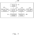
- FIG. 7 is a block diagram of modules of the electronic device of FIG. 1 .
- FIG. 8 is a schematic view of an electronic device according to a second embodiment of the present disclosure, with a first lens module completely deployed.
- FIG. 9 is an isometric view of part of the electronic device of FIG. 8 , with the first lens module flipped predetermined degrees.
- the element when an element is described as being “fixed to” another element, the element can be fixed to the another element with or without intermediate elements.
- the element when an element is described as “connecting” another element, the element can be connected to the another element with or without intermediate elements.
- a first embodiment of an electronic device 200 includes a main body 201 including a display screen 10 and a housing 20 .
- the electronic device 200 further includes a first lens module 30 , and a second lens module 40 mounted on the main body 201 .
- the electronic device 200 may further include, but is not limited to, other mechanical structures, other electronic components, modules, and software that implement their preset functions.
- the electronic device 200 may be any one of various portable electronic devices such as tablet computers, smart phones, and personal digital processing devices (PDAs).
- the display screen 10 can be used for display.
- the display screen 10 can be any type of display screen, such as an LCD (Liquid Crystal Display), an OLED (Organic Light-Emitting Diode), or the like.
- the display screen 10 is an “infinity screen”. In another embodiment, the display screen 10 is not an “infinity screen”.
- the main body 201 includes a front surface 11 and a back surface 12 .
- the display screen 10 is disposed on the front surface 11 .
- the first lens module 30 and the second lens module 40 are disposed on the back surface 12 .
- the housing 20 also includes a top wall 21 , a bottom wall 22 , and two side walls 23 .
- the top wall 21 , the bottom wall 22 and the side walls 23 corporately define a shape of the housing 20 .
- the housing 20 has a substantially rectangular shape for accommodating the display screen 10 .
- the top wall 21 , the bottom wall 22 , and the side walls 23 connect the front surface 11 and the back surface 12 to form an outline of the electronic device 200 .
- the back surface 12 of the housing 20 defines a receiving groove 211 .
- the receiving groove 211 is substantially rectangular.
- the receiving groove 211 is substantially U-shaped, and has an opening facing away from the bottom wall 22 .
- the opening of the receiving groove 211 penetrates the top wall 21 .
- the first lens module 30 is received in the receiving groove 211 .
- the receiving groove 211 can be disposed to be adjacent to either one of the bottom wall 22 and the side walls 23 .
- the first lens module 30 is slidably disposed in the receiving groove 211 .
- the first lens module 30 can slide in the receiving groove 211 to extend out of the receiving groove 211 .
- the first lens module 30 is prevented from sliding out and separating from the housing 20 .
- the first lens module 30 can be completely received in the receiving groove 211 .
- the shape of the receiving groove 211 is substantially the same as the shape of the first lens module 30 .
- the second lens module 40 is disposed on the housing 20 adjacent to the receiving groove 211 .
- the second lens module 40 is used to capture a scene at the rear of the electronic device 200 .
- the first lens module 30 When the first lens module 30 is slid out of the receiving groove 211 , the first lens module 30 can be rotated relative to the housing 20 , so that it can be used to capture a front scene of the electronic device 200 as well as a rear scene.
- the electronic device 200 includes a rotating member (not labeled).
- the first lens module 30 can be rotated relative to the housing 20 with the rotating member.
- FIG. 3 when not rotated with respect to the housing 20 , the first lens module 30 and the second lens module 40 face a back side of the electronic device 200 , and both can be used to capture the scene at the rear of the electronic device 200 . As shown in FIG.
- the first lens module 30 is rotated such as 180 degrees with respect to the housing 20 and faces a front side of the electronic device 200 .
- the first lens module 30 thus can be used to capture the front scene of the electronic device 200 .
- the first lens module 30 can be rotated to any other angle.
- the first lens module 30 can be manually controlled by a user to slide out of the receiving groove 211 and then be rotated around a rotating shaft 31 .
- the first lens module 30 can be controlled by a control unit (not shown) to automatically slide out of the receiving groove 211 and then automatically rotate around the rotating shaft 31 .
- the first lens module 30 and the second lens module 40 can both be used to capture the rear scene when the first lens module 30 is received in the receiving groove 211 , or when the first lens module 30 is slid out of the receiving groove 211 but is not rotated relative to the housing 20 .
- the first lens module 30 can be used to capture the front scene and the second lens module 40 can be used to capture the rear scene when the first lens module 30 is slid out of the receiving groove 211 and rotated to face the front side of the electronic device 20 .
- the first lens module 30 can be further rotated to any other angle with respect to the housing 20 to capture a scene at any orientation relative to the electronic device 200 .
- the electronic device 200 further includes a detection module 50 , a control module 60 , a prompting module 70 , and a connection module 80 .
- the detection module 50 can be disposed on the housing 20 or on a supporting member 32 which supports the first lens module 30 .
- the detection module 50 detects whether the first lens module 30 reaches a preset position, for example, the detection module 50 detects whether the first lens module 30 is slid to a preset location and further detects whether the first lens module 30 is rotated to a preset angle.
- the preset position is the limit of travel of the first lens module 30 out of the receiving groove 211 .
- the preset position is where the first lens module 30 is completely received in the receiving groove 211 .
- the control module 60 can be a central processing unit, a microprocessor, or any chip with data processing functions.
- the control module 60 signals the prompting module 70 to generate a prompt message to inform the user if the first lens module 30 is not slid to the preset position and/or the first lens module 30 is not rotated to the preset angle. Incorrect shooting is thus prevented.
- the control module 60 itself stops the first lens module from incorrect shooting when a shooting instruction is received from the user but the first lens module 30 is not slid to the preset position and/or the first lens module 30 is not rotated to the preset angle.
- the control module 60 is further configured to control the first lens module 30 and the second lens module 40 to perform a joint shooting operation when receiving a joint shooting instruction from the user.
- the joint shooting operation is that the first lens module 30 captures a first image and the second lens module 40 captures a second image, the capturing is done simultaneously.
- a third image that is a composite image of the first image and the second image can be generated under control of the control module 60 .
- the third image generally has a better appearance with respect to the first image and the second image.
- the third image may be clearer or may have a higher resolution as compared to the first image and the second image.
- a successful joint shooting operation requires that the first lens module 30 and the second lens module 40 are separated by a predetermined distance.
- the preset position of the first lens module 30 is where the first lens module 30 is spaced from the second lens module 40 for such predetermined distance.
- the control module 60 controls the prompting module 70 to prompt the user.
- a prompt information may be in form of text, sound, and/or by light.
- the prompt information of text form is displayed on the display screen 10 to remind the user.
- the prompt information in sound (may be a voice) form is broadcast by a speaker module (not labeled) to remind the user.
- the prompt information by light form is shown by a flash 71 of the first lens module 30 .
- connection module 80 is configured to electrically connect the first lens module 30 , the detection module 50 , and the control module 60 .
- the connection module 80 can include a connector 81 and a signal line 82 .
- the first lens module 30 being slidably disposed on the back surface 12 of the electronic device 200 means that it does not occupy the front surface 11 of the electronic device 200 .
- the size of the display screen 10 on the front surface 11 is thus not affected by the first lens module 30 and a larger size display screen 10 can be provided on the electronic device 200 .
- a second embodiment of an electronic device includes a main body 201 including a display screen 10 and a housing 20 .
- the electronic device 200 further includes a first lens module 30 , and a second lens module 40 mounted on the main body 201 .
- the electronic device 200 may further include, but is not limited to, other mechanical structures, other electronic components, modules, and software that implement their preset functions.
- the electronic device 200 may be any one of various portable electronic devices such as tablet computers, smart phones, and personal digital processing devices (PDAs).
- the display screen 10 can be used for display.
- the display screen 10 can be any type of display screen, such as an LCD (Liquid Crystal Display), an OLED (Organic Light-Emitting Diode), or the like.
- the display screen 10 is an “infinity screen”. In another embodiment, the display screen 10 is not an “infinity screen”.
- the housing 20 includes a front surface 11 and a back surface 12 .
- the display screen 10 is disposed on the front surface 11 .
- the first lens module 30 and the second lens module 40 are disposed on the back surface 12 .
- the housing 20 also includes a top wall 21 , a bottom wall 22 , and two side walls 23 .
- the top wall 21 , the bottom wall 22 and the side walls 23 corporately define a shape of the housing 20 .
- the housing 20 has a substantially rectangular shape for accommodating the display screen 10 .
- the top wall 21 , the bottom wall 22 , and the side walls 23 connect the front surface 11 and the back surface 12 to form the outline of the electronic device 200 .
- the back surface 12 of the housing 20 defines a receiving groove 211 .
- the receiving groove 211 is substantially rectangular and located at a substantially intermediate portion of the top wall 21 .
- the receiving groove 211 is substantially U-shaped, and has an opening facing away from the bottom wall 22 .
- the opening of the receiving groove 211 penetrates the top wall 21 .
- the first lens module 30 is received in the receiving groove 211 . It can be understood that in another embodiment, the receiving groove 211 can be disposed on any one of the bottom wall 22 and the two side walls 23 .
- the first lens module 30 is reversibly disposed in the receiving groove 211 , and the first lens module 30 can be reversed or flipped relative to the housing 20 and rotated out of the receiving groove 211 .
- the flipping of the first lens module 30 may be carry out by rotating the first lens module 30 around an axis vertical to a plane in which the side walls 23 are located.
- the first lens module 30 can be completely flipped or unflipped in the receiving groove 211 . As shown in FIG. 4 , the first lens module 30 is completely flipped with respect to the housing 20 , that is, the first lens module 30 is rotated for predetermined degrees such as 180 degrees out of the receiving groove 211 .
- the first lens module 30 faces a front side of the electronic device 200 , and can be used to capture a front scene of the electronic device 200 . As shown in FIG. 2 , the first lens module 30 is not inverted and is still received in the receiving groove 211 . The first lens module 30 faces a back side of the electronic device 200 , and can be used to capture a rear scene of the electronic device 200 . As shown in FIG. 8 , the first lens module 30 is not completely flipped. That is, the first lens module 30 is partially flipped and rotated less than the predetermined degrees such as 180 degrees. In the embodiment, the first lens module 30 can be manually controlled by a user to be flipped to any angle desired that is not greater than the predetermined degrees. In an alternative embodiment, the first lens module 30 can be automatically flipped by a control unit (not shown).
- the second lens module 40 is disposed on the housing 20 adjacent to the receiving groove 211 .
- the second lens module 40 is used to capture a rear scene of the electronic device 200 .
- the first lens module 30 When the first lens module 30 is completely flipped, the first lens module 30 can be used to capture the front scene of the electronic device 200 , and the second lens module 40 can be used to capture a rear scene of the electronic device 200 .
- the first lens module 30 When the first lens module 30 is received in the receiving groove 211 and is unflipped, the first lens module 30 and the second lens module 40 can both be used to capture the rear scene of the electronic device 200 .
- the first lens module 30 can be further flipped to any other angle to capture a scene around the electronic device 200 .
- the electronic device 200 further includes a detection module 50 , a control module 60 , a prompting module 70 , and a connection module 80 .
- the detection module 50 is disposed on the housing 20 .
- the detection module 50 is configured to detect an unflipped, a partially flipped, and a completely flipped state of the first lens module 30 .
- the completely flipped state is that the first lens module 30 is flipped out of the receiving groove 211 for the predetermined degrees such as 180 degrees.
- the partially flipped state is that the first lens module 30 is flipped out of the receiving groove 211 for less than the predetermined degrees such as 180 degrees.
- the unflipped state is that the first lens module 30 is completely received in the receiving groove 211 .
- the control module 60 can be a central processing unit, a microprocessor or any chip with data processing functions.
- control module 60 When a shooting instruction is received from the user the control module 60 signals the prompting module 70 to generate a prompt message warning that the first lens module 30 is not completely flipped, to prevent incorrect shooting. In an alternative embodiment, the control module 60 itself stops the first lens module from incorrect shooting when a shooting instruction is received from the user but the first lens module 30 is not completely flipped.
- the control module 60 is further configured to control the first lens module 30 and the second lens module 40 to perform a joint shooting operation when receiving a joint shooting instruction from the user and the first lens module 30 is at the unflipped state.
- the joint shooting operation is that, simultaneously, the first lens module 30 captures a first image and the second lens module 40 captures a second image.
- a third image that is a composite image of the first image and the second image can be generated under control of the control module 60 .
- the prompt information may be in form of text, sound, and/or light.
- connection module 80 is configured to electrically connect the first lens module 30 , the detection module 50 , and the control module 60 .
- the connection module 80 can include a connector 81 and a signal line 82 .
- the first lens module 30 being reversibly disposed on the back surface 12 of the electronic device 200 means that it does not occupy the front surface 11 of the electronic device 200 .
- the size of the display screen 10 on the front surface 11 is thus not affected by the first lens module 30 and a larger size display screen 10 can be provided on the electronic device 200 .
- Embodiments of a controlling method suitable for a first lens module and/or a second lens module to capture a front scene and a rear scene are also provided.
- the method includes steps of: defining a receiving groove on a housing of an electronic device and stretchably mounting a front lens module in the receiving groove, thereby the first the first lens module being capable of capturing a rear scene when being received in the receiving groove and capable of capturing a front scene when being stretched out of the receiving groove; and providing a control module to conduct the first lens module to capture the rear scene of the electronic device when the first lens module is received in the receiving groove and a shooting instruction is received from a user, and to conduct the first lens module to capture the front scene of the electronic device when the first lens module is stretched out of the receiving groove and a shooting instruction is received from the user.
- the method further includes steps of: detecting whether the first lens module reaches a preset position; and generating a prompt message to inform the user or not activating the first lens module when a shooting instruction is received from the user but the first lens module does not reach the preset position.
- the preset position is where the first lens module being completely out of the receiving groove or where the first lens module being completely received in the receiving groove.
- the method further includes steps of: mounting a second lens module adjacent to the receiving groove; controlling the first lens module and the second lens module by the controller to perform a joint shooting operation upon receiving a joint shooting instruction from the user; and generating a composite image.
- the joint shooting operation is that the first lens module captures a first image and the second lens module capture a second image, the composite image is a composite of the first image and the second image.
- the method further includes steps of: detecting whether the first lens module reaches a preset position; and generating a prompt message to inform the user or not activating the joint shooting operation when a joint shooting instruction is received from the user but the first lens module does not reach the preset position.
- the preset position is where the first lens module is spaced from the second lens module for a predetermined distance.
Landscapes
- Engineering & Computer Science (AREA)
- Signal Processing (AREA)
- Multimedia (AREA)
- Physics & Mathematics (AREA)
- General Physics & Mathematics (AREA)
- Optics & Photonics (AREA)
- Human Computer Interaction (AREA)
- Studio Devices (AREA)
Abstract
Description
Claims (18)
Applications Claiming Priority (2)
| Application Number | Priority Date | Filing Date | Title |
|---|---|---|---|
| CN201811044017.1A CN110891099B (en) | 2018-09-07 | 2018-09-07 | Electronic device |
| CN201811044017.1 | 2018-09-07 |
Publications (2)
| Publication Number | Publication Date |
|---|---|
| US20200081227A1 US20200081227A1 (en) | 2020-03-12 |
| US11099357B2 true US11099357B2 (en) | 2021-08-24 |
Family
ID=69719551
Family Applications (1)
| Application Number | Title | Priority Date | Filing Date |
|---|---|---|---|
| US16/562,876 Active 2039-10-08 US11099357B2 (en) | 2018-09-07 | 2019-09-06 | Electronic device with deployable and retractable camera assembly |
Country Status (2)
| Country | Link |
|---|---|
| US (1) | US11099357B2 (en) |
| CN (1) | CN110891099B (en) |
Families Citing this family (14)
| Publication number | Priority date | Publication date | Assignee | Title |
|---|---|---|---|---|
| CN111917904B (en) * | 2019-05-10 | 2022-05-06 | 深圳富泰宏精密工业有限公司 | Control method and electronic device |
| WO2021021073A1 (en) * | 2019-07-26 | 2021-02-04 | Hewlett-Packard Development Company, L.P. | Adjustable camera systems for displays |
| CN210112121U (en) * | 2019-08-20 | 2020-02-21 | 三赢科技(深圳)有限公司 | Camera module and electronic device with same |
| CN111405155A (en) * | 2020-03-20 | 2020-07-10 | 维沃移动通信有限公司 | Electronics and Standalone Camera Modules |
| US12158782B2 (en) * | 2020-11-08 | 2024-12-03 | Lepton Computing Llc | 360 degree camera functions through a foldable mobile device |
| CN116670553A (en) * | 2021-02-08 | 2023-08-29 | Oppo广东移动通信有限公司 | Imaging lens assembly, camera module and imaging device |
| US11838433B1 (en) * | 2022-10-17 | 2023-12-05 | Motorola Mobility Llc | Electronic devices with translating flexible displays and corresponding methods for automatic transition to peek position |
| US12250332B2 (en) | 2022-10-17 | 2025-03-11 | Motorola Mobility Llc | Electronic devices with translating flexible display and corresponding methods |
| US12549653B2 (en) | 2022-10-17 | 2026-02-10 | Motorola Mobility Llc | Methods and systems for controlling a translating flexible display of an electronic device in response to scrolling user input |
| US12346171B2 (en) * | 2022-10-17 | 2025-07-01 | Motorola Mobility Llc | Electronic devices with translating flexible displays and corresponding methods for automatic transition to peek position |
| US12487640B2 (en) | 2022-10-17 | 2025-12-02 | Motorola Mobility Llc | Electronic devices with translating flexible displays and corresponding methods for managing display position as a function content presentation |
| US12035035B1 (en) | 2023-03-27 | 2024-07-09 | Motorola Mobility Llc | Methods and systems for controlling a translating flexible display of an electronic device in response to zoom gesture user input |
| US12034879B1 (en) | 2023-03-27 | 2024-07-09 | Motorola Mobility Llc | Methods and systems for controlling a translating flexible display of an electronic device in response to pinch gesture user input |
| WO2024250269A1 (en) | 2023-06-09 | 2024-12-12 | Motorola Mobility Llc | Electronic devices with translating flexible displays and corresponding methods for presenting notifications without resizing presented application portals |
Citations (10)
| Publication number | Priority date | Publication date | Assignee | Title |
|---|---|---|---|---|
| US20070120960A1 (en) * | 2005-11-11 | 2007-05-31 | Hon Hai Precision Industry Co., Ltd. | Portable electronic device with a rotatable camera module |
| US7474298B2 (en) * | 2002-05-31 | 2009-01-06 | Palm, Inc. | Mobile device having an adjustable length to selectively expose a surface component |
| CN104301609A (en) | 2014-09-26 | 2015-01-21 | 深圳市欧珀通信软件有限公司 | A camera rotation control method applied to a mobile terminal and the mobile terminal |
| US20150138314A1 (en) * | 2013-11-20 | 2015-05-21 | Google Inc. | Generating Panoramic Images |
| CN105049569A (en) | 2015-08-20 | 2015-11-11 | 擎亚国际贸易(上海)有限公司 | Panoramic photo composition method based on front and back cameras of cellphone |
| CN106686291A (en) | 2017-01-24 | 2017-05-17 | 北京小米移动软件有限公司 | Electronic equipment |
| CN108388314A (en) * | 2018-04-04 | 2018-08-10 | 深圳天珑无线科技有限公司 | A kind of electronic equipment and its CCD camera assembly |
| US20180292866A1 (en) * | 2017-04-08 | 2018-10-11 | Lenovo (Singapore) Pte. Ltd. | Retractable camera |
| US20180295328A1 (en) * | 2017-04-08 | 2018-10-11 | Lenovo (Singapore) Pte. Ltd. | Positionable camera |
| US20180332204A1 (en) * | 2011-11-14 | 2018-11-15 | Tseng-Lu Chien | LED Light Has Built-In Camera-Assembly for Colorful Digital-Data Under Dark Environment |
Family Cites Families (2)
| Publication number | Priority date | Publication date | Assignee | Title |
|---|---|---|---|---|
| CN104254220A (en) * | 2013-06-26 | 2014-12-31 | 鸿富锦精密工业(深圳)有限公司 | Portable electronic device |
| CN103581523B (en) * | 2013-10-21 | 2017-06-16 | 路宽 | Telescopic rotatable camera |
-
2018
- 2018-09-07 CN CN201811044017.1A patent/CN110891099B/en active Active
-
2019
- 2019-09-06 US US16/562,876 patent/US11099357B2/en active Active
Patent Citations (10)
| Publication number | Priority date | Publication date | Assignee | Title |
|---|---|---|---|---|
| US7474298B2 (en) * | 2002-05-31 | 2009-01-06 | Palm, Inc. | Mobile device having an adjustable length to selectively expose a surface component |
| US20070120960A1 (en) * | 2005-11-11 | 2007-05-31 | Hon Hai Precision Industry Co., Ltd. | Portable electronic device with a rotatable camera module |
| US20180332204A1 (en) * | 2011-11-14 | 2018-11-15 | Tseng-Lu Chien | LED Light Has Built-In Camera-Assembly for Colorful Digital-Data Under Dark Environment |
| US20150138314A1 (en) * | 2013-11-20 | 2015-05-21 | Google Inc. | Generating Panoramic Images |
| CN104301609A (en) | 2014-09-26 | 2015-01-21 | 深圳市欧珀通信软件有限公司 | A camera rotation control method applied to a mobile terminal and the mobile terminal |
| CN105049569A (en) | 2015-08-20 | 2015-11-11 | 擎亚国际贸易(上海)有限公司 | Panoramic photo composition method based on front and back cameras of cellphone |
| CN106686291A (en) | 2017-01-24 | 2017-05-17 | 北京小米移动软件有限公司 | Electronic equipment |
| US20180292866A1 (en) * | 2017-04-08 | 2018-10-11 | Lenovo (Singapore) Pte. Ltd. | Retractable camera |
| US20180295328A1 (en) * | 2017-04-08 | 2018-10-11 | Lenovo (Singapore) Pte. Ltd. | Positionable camera |
| CN108388314A (en) * | 2018-04-04 | 2018-08-10 | 深圳天珑无线科技有限公司 | A kind of electronic equipment and its CCD camera assembly |
Non-Patent Citations (1)
| Title |
|---|
| English Translation of CN108388314 (Year: 2018). * |
Also Published As
| Publication number | Publication date |
|---|---|
| US20200081227A1 (en) | 2020-03-12 |
| CN110891099B (en) | 2022-03-22 |
| CN110891099A (en) | 2020-03-17 |
Similar Documents
| Publication | Publication Date | Title |
|---|---|---|
| US11099357B2 (en) | Electronic device with deployable and retractable camera assembly | |
| TWI657368B (en) | Display method and device, display screen and mobile terminal | |
| US9667906B2 (en) | Display apparatus | |
| KR20150124710A (en) | Mobile terminal case and mobile terminal | |
| KR20140147597A (en) | Mobile terminal and control method for the mobile terminal | |
| US11294430B1 (en) | Media device including display and power-delivery mechanism with integrated stand | |
| US11212930B2 (en) | Media device including display and power-delivery mechanism with integrated stand | |
| KR102241073B1 (en) | Mobile terminal | |
| KR20160008372A (en) | Mobile terminal and control method for the mobile terminal | |
| US9859942B2 (en) | Protective cover and portable electronic device assembly employing the same | |
| KR20170057058A (en) | Mobile terminal and method for controlling the same | |
| US8767392B2 (en) | Portable electronic device | |
| EP3687154B1 (en) | Camera assembly and terminal | |
| US11005981B2 (en) | Camera module and electronic device including the same | |
| KR20180025864A (en) | Camera module and mobile terminal having the same | |
| KR102238532B1 (en) | Mobile terminal and method for controlling the same | |
| US20130038697A1 (en) | Wireless communication device with dual imaging units | |
| KR20160003522A (en) | Mobile terminal | |
| US9811160B2 (en) | Mobile terminal and method for controlling the same | |
| US11856120B2 (en) | Mobile terminal | |
| US20150194133A1 (en) | Portable electronic device with projecting function and projecting method thereof | |
| KR102053902B1 (en) | Moblie apparatus and hinge module used therein | |
| CN108696698B (en) | Image pickup device, electronic equipment and image acquisition method | |
| KR101984089B1 (en) | Mobile terminal | |
| KR20110043350A (en) | Mobile terminal |
Legal Events
| Date | Code | Title | Description |
|---|---|---|---|
| AS | Assignment |
Owner name: CHIUN MAI COMMUNICATION SYSTEMS, INC., TAIWAN Free format text: ASSIGNMENT OF ASSIGNORS INTEREST;ASSIGNOR:HUANG, CHUN-NAN;REEL/FRAME:050293/0864 Effective date: 20190906 |
|
| FEPP | Fee payment procedure |
Free format text: ENTITY STATUS SET TO UNDISCOUNTED (ORIGINAL EVENT CODE: BIG.); ENTITY STATUS OF PATENT OWNER: LARGE ENTITY |
|
| STPP | Information on status: patent application and granting procedure in general |
Free format text: NON FINAL ACTION MAILED |
|
| STPP | Information on status: patent application and granting procedure in general |
Free format text: RESPONSE TO NON-FINAL OFFICE ACTION ENTERED AND FORWARDED TO EXAMINER |
|
| STPP | Information on status: patent application and granting procedure in general |
Free format text: NOTICE OF ALLOWANCE MAILED -- APPLICATION RECEIVED IN OFFICE OF PUBLICATIONS |
|
| STPP | Information on status: patent application and granting procedure in general |
Free format text: AWAITING TC RESP., ISSUE FEE NOT PAID |
|
| STPP | Information on status: patent application and granting procedure in general |
Free format text: NOTICE OF ALLOWANCE MAILED -- APPLICATION RECEIVED IN OFFICE OF PUBLICATIONS |
|
| STPP | Information on status: patent application and granting procedure in general |
Free format text: PUBLICATIONS -- ISSUE FEE PAYMENT RECEIVED |
|
| STCF | Information on status: patent grant |
Free format text: PATENTED CASE |
|
| MAFP | Maintenance fee payment |
Free format text: PAYMENT OF MAINTENANCE FEE, 4TH YEAR, LARGE ENTITY (ORIGINAL EVENT CODE: M1551); ENTITY STATUS OF PATENT OWNER: LARGE ENTITY Year of fee payment: 4 |