US11097455B2 - Multi-shot mold process and assembly for producing a vehicle panel - Google Patents
Multi-shot mold process and assembly for producing a vehicle panel Download PDFInfo
- Publication number
- US11097455B2 US11097455B2 US16/214,512 US201816214512A US11097455B2 US 11097455 B2 US11097455 B2 US 11097455B2 US 201816214512 A US201816214512 A US 201816214512A US 11097455 B2 US11097455 B2 US 11097455B2
- Authority
- US
- United States
- Prior art keywords
- shot
- panel
- injection molding
- skin
- cavity
- Prior art date
- Legal status (The legal status is an assumption and is not a legal conclusion. Google has not performed a legal analysis and makes no representation as to the accuracy of the status listed.)
- Active, expires
Links
- 238000000034 method Methods 0.000 title claims description 30
- 238000001746 injection moulding Methods 0.000 claims abstract description 43
- 238000002347 injection Methods 0.000 claims abstract description 17
- 239000007924 injection Substances 0.000 claims abstract description 17
- 238000004891 communication Methods 0.000 claims abstract description 8
- 229920001169 thermoplastic Polymers 0.000 claims abstract description 7
- 239000004416 thermosoftening plastic Substances 0.000 claims abstract description 7
- 238000004519 manufacturing process Methods 0.000 claims abstract description 3
- 230000001747 exhibiting effect Effects 0.000 claims abstract 2
- 229920002397 thermoplastic olefin Polymers 0.000 claims description 6
- 238000000465 moulding Methods 0.000 description 24
- 239000000463 material Substances 0.000 description 22
- 230000015572 biosynthetic process Effects 0.000 description 17
- 244000208734 Pisonia aculeata Species 0.000 description 11
- 239000012815 thermoplastic material Substances 0.000 description 6
- 229920002725 thermoplastic elastomer Polymers 0.000 description 5
- 229920001971 elastomer Polymers 0.000 description 4
- 239000000945 filler Substances 0.000 description 4
- 238000000429 assembly Methods 0.000 description 3
- 230000000712 assembly Effects 0.000 description 3
- 238000010276 construction Methods 0.000 description 3
- 238000001125 extrusion Methods 0.000 description 3
- 239000000806 elastomer Substances 0.000 description 2
- 239000012530 fluid Substances 0.000 description 2
- 239000000203 mixture Substances 0.000 description 2
- 239000004033 plastic Substances 0.000 description 2
- 229920003023 plastic Polymers 0.000 description 2
- 229920000642 polymer Polymers 0.000 description 2
- 244000226021 Anacardium occidentale Species 0.000 description 1
- 235000020226 cashew nut Nutrition 0.000 description 1
- 230000002708 enhancing effect Effects 0.000 description 1
- 239000000835 fiber Substances 0.000 description 1
- 230000004927 fusion Effects 0.000 description 1
- 238000010348 incorporation Methods 0.000 description 1
- 239000002861 polymer material Substances 0.000 description 1
- 230000000750 progressive effect Effects 0.000 description 1
- 230000002787 reinforcement Effects 0.000 description 1
- 239000007779 soft material Substances 0.000 description 1
- 230000003068 static effect Effects 0.000 description 1
- 238000003466 welding Methods 0.000 description 1
Images


Classifications
-
- B—PERFORMING OPERATIONS; TRANSPORTING
- B29—WORKING OF PLASTICS; WORKING OF SUBSTANCES IN A PLASTIC STATE IN GENERAL
- B29C—SHAPING OR JOINING OF PLASTICS; SHAPING OF MATERIAL IN A PLASTIC STATE, NOT OTHERWISE PROVIDED FOR; AFTER-TREATMENT OF THE SHAPED PRODUCTS, e.g. REPAIRING
- B29C45/00—Injection moulding, i.e. forcing the required volume of moulding material through a nozzle into a closed mould; Apparatus therefor
- B29C45/16—Making multilayered or multicoloured articles
- B29C45/1615—The materials being injected at different moulding stations
- B29C45/162—The materials being injected at different moulding stations using means, e.g. mould parts, for transferring an injected part between moulding stations
-
- B—PERFORMING OPERATIONS; TRANSPORTING
- B29—WORKING OF PLASTICS; WORKING OF SUBSTANCES IN A PLASTIC STATE IN GENERAL
- B29C—SHAPING OR JOINING OF PLASTICS; SHAPING OF MATERIAL IN A PLASTIC STATE, NOT OTHERWISE PROVIDED FOR; AFTER-TREATMENT OF THE SHAPED PRODUCTS, e.g. REPAIRING
- B29C45/00—Injection moulding, i.e. forcing the required volume of moulding material through a nozzle into a closed mould; Apparatus therefor
- B29C45/03—Injection moulding apparatus
- B29C45/04—Injection moulding apparatus using movable moulds or mould halves
- B29C45/0441—Injection moulding apparatus using movable moulds or mould halves involving a rotational movement
-
- B—PERFORMING OPERATIONS; TRANSPORTING
- B29—WORKING OF PLASTICS; WORKING OF SUBSTANCES IN A PLASTIC STATE IN GENERAL
- B29C—SHAPING OR JOINING OF PLASTICS; SHAPING OF MATERIAL IN A PLASTIC STATE, NOT OTHERWISE PROVIDED FOR; AFTER-TREATMENT OF THE SHAPED PRODUCTS, e.g. REPAIRING
- B29C45/00—Injection moulding, i.e. forcing the required volume of moulding material through a nozzle into a closed mould; Apparatus therefor
- B29C45/16—Making multilayered or multicoloured articles
- B29C45/1615—The materials being injected at different moulding stations
-
- B—PERFORMING OPERATIONS; TRANSPORTING
- B29—WORKING OF PLASTICS; WORKING OF SUBSTANCES IN A PLASTIC STATE IN GENERAL
- B29C—SHAPING OR JOINING OF PLASTICS; SHAPING OF MATERIAL IN A PLASTIC STATE, NOT OTHERWISE PROVIDED FOR; AFTER-TREATMENT OF THE SHAPED PRODUCTS, e.g. REPAIRING
- B29C45/00—Injection moulding, i.e. forcing the required volume of moulding material through a nozzle into a closed mould; Apparatus therefor
- B29C45/17—Component parts, details or accessories; Auxiliary operations
- B29C45/26—Moulds
- B29C45/33—Moulds having transversely, e.g. radially, movable mould parts
-
- B—PERFORMING OPERATIONS; TRANSPORTING
- B62—LAND VEHICLES FOR TRAVELLING OTHERWISE THAN ON RAILS
- B62D—MOTOR VEHICLES; TRAILERS
- B62D25/00—Superstructure or monocoque structure sub-units; Parts or details thereof not otherwise provided for
- B62D25/02—Side panels
- B62D25/025—Side sills thereof
-
- B—PERFORMING OPERATIONS; TRANSPORTING
- B29—WORKING OF PLASTICS; WORKING OF SUBSTANCES IN A PLASTIC STATE IN GENERAL
- B29C—SHAPING OR JOINING OF PLASTICS; SHAPING OF MATERIAL IN A PLASTIC STATE, NOT OTHERWISE PROVIDED FOR; AFTER-TREATMENT OF THE SHAPED PRODUCTS, e.g. REPAIRING
- B29C45/00—Injection moulding, i.e. forcing the required volume of moulding material through a nozzle into a closed mould; Apparatus therefor
- B29C2045/0093—Injection moulding, i.e. forcing the required volume of moulding material through a nozzle into a closed mould; Apparatus therefor of articles provided with an attaching element
-
- B—PERFORMING OPERATIONS; TRANSPORTING
- B29—WORKING OF PLASTICS; WORKING OF SUBSTANCES IN A PLASTIC STATE IN GENERAL
- B29C—SHAPING OR JOINING OF PLASTICS; SHAPING OF MATERIAL IN A PLASTIC STATE, NOT OTHERWISE PROVIDED FOR; AFTER-TREATMENT OF THE SHAPED PRODUCTS, e.g. REPAIRING
- B29C45/00—Injection moulding, i.e. forcing the required volume of moulding material through a nozzle into a closed mould; Apparatus therefor
- B29C45/16—Making multilayered or multicoloured articles
- B29C45/1676—Making multilayered or multicoloured articles using a soft material and a rigid material, e.g. making articles with a sealing part
-
- B—PERFORMING OPERATIONS; TRANSPORTING
- B29—WORKING OF PLASTICS; WORKING OF SUBSTANCES IN A PLASTIC STATE IN GENERAL
- B29K—INDEXING SCHEME ASSOCIATED WITH SUBCLASSES B29B, B29C OR B29D, RELATING TO MOULDING MATERIALS OR TO MATERIALS FOR MOULDS, REINFORCEMENTS, FILLERS OR PREFORMED PARTS, e.g. INSERTS
- B29K2023/00—Use of polyalkenes or derivatives thereof as moulding material
-
- B—PERFORMING OPERATIONS; TRANSPORTING
- B29—WORKING OF PLASTICS; WORKING OF SUBSTANCES IN A PLASTIC STATE IN GENERAL
- B29K—INDEXING SCHEME ASSOCIATED WITH SUBCLASSES B29B, B29C OR B29D, RELATING TO MOULDING MATERIALS OR TO MATERIALS FOR MOULDS, REINFORCEMENTS, FILLERS OR PREFORMED PARTS, e.g. INSERTS
- B29K2101/00—Use of unspecified macromolecular compounds as moulding material
- B29K2101/12—Thermoplastic materials
-
- B—PERFORMING OPERATIONS; TRANSPORTING
- B29—WORKING OF PLASTICS; WORKING OF SUBSTANCES IN A PLASTIC STATE IN GENERAL
- B29L—INDEXING SCHEME ASSOCIATED WITH SUBCLASS B29C, RELATING TO PARTICULAR ARTICLES
- B29L2031/00—Other particular articles
- B29L2031/30—Vehicles, e.g. ships or aircraft, or body parts thereof
- B29L2031/3005—Body finishings
- B29L2031/3041—Trim panels
Definitions
- the present invention discloses an in-mold multi-shot injection molding assembly, method and article for producing a vehicle panel, such as a rocker panel.
- the assembly and method aspects include, in any variant, a first injection molded doghouse and a second stage injection molded panel skin.
- the present design eliminates the necessity of secondary operations during the assembly of an interior bracket of the panel or molding.
- a third stage injection molding or separate extrusion of such as a seal can be applied to the vehicle panel in a further variant.
- vehicle panel designs such as produced by injection molding techniques.
- This can include the injection molding formation of the panel being supplemented by a secondary stage post injection molding assembly operation in which an inner attachment bracket is separately provided and is heat staked or otherwise secured to an inside surface of the rocker molding.
- the inner attachment bracket in turn supports a dog house or clip assembly for attaching the panel to a suitably configured location of the vehicle.
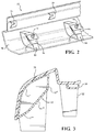
- FIGS. 1A-1C An example of a conventional panel is depicted in FIGS. 1A-1C which illustrates an existing rocker panel design 2 , and in, following an injection molding of the panel in a static (non-rotating) single shot mold, a secondary post molding assembly operation is required for attaching, such as via heat staking, an inner bracket 4 to the previously molded panel 6 . Also shown are examples of doghouse supported clips 7 attached to various locations of the panel.
- FIG. 1B is a side plan cutaway of the panel of FIG. 1A , again according to the Prior Art, and which depicts the heat staking (see at location 8 ) of the inner attachment bracket 4 to the molded panel.
- FIG. 1C additionally provides an inside plan view of the two panel design of FIG. 1A .
- rocker panel body has a first end feature situated on a first end of the rocker panel body and a second end feature situated on a second end of the rocker panel body.
- the rocker panel body provides an outside surface generally presented in the form of a convex surface, and an inside surface generally presented in the form of a concave surface.
- the outside surface of the rocker panel body extends outwardly of the vehicle, to present an outboard section having a predetermined profile based on targeted aesthetic/performance characteristics.
- the inside surface of the rocker panel body has at least one transverse rib positioned therein, the transverse rib being arranged generally perpendicular to the longitudinal axis of the rocker panel body.
- a door trim panel for a vehicle which includes an inner surface for facing a vehicle interior and an outer or “B” surface facing the inside of a vehicle door.
- Various components typically found on the “B” surface of the door trim panel are added to the panel in the present invention by a molding process.
- the components are preferably formed from a thermoplastic, and the door trim panel itself comprises a fiber or thermoplastic panel capable of forming a mechanical or a fusion bond with the components.
- Examples of the components which may be added to a panel using the present invention include locators, ribs or other reinforcement members, attachments for wire harnesses, supports, doghouses, flanges, etc. It is also desirable to use recycled material in the panel.
- U.S. Pat. No. 6,171,543, to Hirose teaches an improved rocker panel construction and method for producing.
- the rocker panel includes a show surface, a hidden surface opposite the show surface, and a plurality of clip house mounting structures, each including a top leg and a bottom leg for connecting the clip house mounting structure to the hidden surface. Additional process steps include each of providing a mold having a mold cavity shaped like the rocker panel, a show surface corresponding to the rocker panel show surface, a hidden surface corresponding to the rocker panel hidden surface.
- Other process features include a top leg cavity portion corresponding to the top leg, a bottom leg cavity portion corresponding to the bottom leg, a first channel-defining surface defining a first channel cavity, the first channel-defining surface being in fluid communication with the bottom leg cavity portion and contiguous with the hidden surface, and at least one sprue in fluid communication with the first channel cavity.
- thermoplastic material injecting a predetermined amount of thermoplastic material into the mold cavity, injecting a predetermined amount of gas into the first channel cavity to form a first strength enhancing rib to resist the tendency of the panel to flex or pivot thereat when the rocker panel is stepped on, and allowing the thermoplastic material to set.
- Floarea U.S. Pat. No. 6,742,835, teaches a rocker panel molding of a polymer material and includes a front section and a rear section joined by bridge arrangements.
- a preferred embodiment includes two bridge elements connected to a rear edge of the front section and to a front edge of the rear section. The bridge elements span a gap between the front and rear edges and allow for longitudinal expansion of the rocker panel moldings to accommodate thermal expansion in the underlying rocker panels and to provide for slight longitudinal adjustment in the rocker panel moldings while fitting the moldings to rocker panels.
- U.S. Pat. No. 7,159,933 to Yamamoto teaches a rocker pane/clip house combination in which a first support member of the clip house is connected to the rocker panel at a first junction that is located between the top surface of the part and a depending side surface. The side surface is connected to a part surface at a second juncture or radiused section. A second support member of the clip house is attached to the surface at a location that is laterally spaced from the second juncture.
- the present invention discloses each of rotary two shot and three shot methods, assemblies and articles for producing a molding or panel, such including but not limited to a vehicle rocker panel.
- the method and assembly aspects improve upon prior art designs by reconfiguring the mold to utilize lifter components within its interior configuration to provide support for injection molding any number of doghouse configurations as part of the first material shot.
- a panel skin is formed in a second shot in communication with the first shot doghouses, following which the completed article is removed from the mold and any supporting clips or the like are attached to the first shot injection molded doghouses as part of any post molding operation.
- a soft flexible seal can be applied to the panel and can be formed either as a third shot injection molded material (such utilizing a second barrel of a different and typically softer material than which is used during the first and second shot injection molding of the doghouses and panel skin).
- the softer seal can be extruded onto a previously two shot produced panel.
- the process and associated tooling can further integrate a core pull-back mechanism during the formation of the third shot flexible seal, and which initially allows a portion of the tooling to block the flow of plastic to the soft seal portion of the tool, following which the blade is retracted to allow for progressive formation of the lip seal or the like, with the soft material of the seal bonding to the second shot rigid material.
- a core pull-back mechanism during the formation of the third shot flexible seal, and which initially allows a portion of the tooling to block the flow of plastic to the soft seal portion of the tool, following which the blade is retracted to allow for progressive formation of the lip seal or the like, with the soft material of the seal bonding to the second shot rigid material.
- the third shot softer seal material can be integrated between separate rigid portions of the second shot skin defining the panel as part of the injection molding process.
- FIG. 1A is an illustration of an existing rocker panel design according to the Prior Art in which a secondary assembly operation is required for attaching, such as via heat staking, an inner bracket to a previously molded panel;
- FIG. 1B is a side plan cutaway of the panel of FIG. 1A according to the Prior Art and which depicts the heat staking of the inner attachment bracket to the molded panel;
- FIG. 1C is an inside plan view of the two panel design of FIG. 1A ;
- FIG. 2 is a perspective view of the two stage injection molded rocker panel according to one non-limiting embodiment of the present invention and illustrating a pair of lifters integrated into the geometry of the die tooling, the lifters providing support location for the first shot injection molding of the doghouse clip structures, the tooling further being manipulated in a second rotary shot fashion for subsequently injection molding the panel skin;
- FIG. 3 is a side plan cutaway of FIG. 2 and illustrating first and second lifter configurations in combination with the second shot panel skin, the first and second molding operations including the provision of a suitable thermoplastic material not limited to a (TPO) thermoplastic olefin, or any other suitable polymer/filler blend usually consisting of some fraction of a thermoplastic, an elastomer or rubber, and usually a filler;
- a suitable thermoplastic material not limited to a (TPO) thermoplastic olefin, or any other suitable polymer/filler blend usually consisting of some fraction of a thermoplastic, an elastomer or rubber, and usually a filler;
- TPO thermoplastic olefin
- any other suitable polymer/filler blend usually consisting of some fraction of a thermoplastic, an elastomer or rubber, and usually a filler
- FIG. 4 is an enlarged and partial perspective illustration of a finished rocker with a first shot injection molded (IM) doghouse (required lifter not shown), the second shot panel again being illustrated;
- IM injection molded
- FIG. 5 is an inside plan view of the two shot panel of FIG. 2 and illustrating the doghouse being produced according to a first shot injection molding operation, following which the tool is rotated and a new cavity (corresponding to the rocker molding) is presented to the previously formed dog house structure for allowing the second shot panel to occur, such being applied in a “skin-over” fashion to the first shot dog houses;
- FIG. 6 is a sectional plan cutaway of the cavity and common core orientation associated with the first injection molding formation of the dog house clips
- FIG. 7 is a sectional plan cutaway corresponding to rotation of the die tool in order to reconfigure the cavity associated with the second injection molding formation of the rocker molding skin;
- FIG. 8 is an illustration similar to FIGS. 6 and 7 of a related process for forming a rocker panel having a third shot seal, such constructed of different material using a second injection molding barrel;
- FIG. 9 is a side cutaway illustration of a panel design depicting a first shot clip attachment, second shot skin and third shot seal;
- FIG. 10 is a further side cutaway illustration of a panel design with a reconfigured third shot seal which interconnect individual sections of the second shot panel skin;
- FIG. 11 depicts an alternate arrangement in which a seal is provided by an extrusion process to the two shot formed panel
- FIG. 12A is a cutaway illustration of a die process for forming a three shot panel similar in respects to that depicted in FIGS. 8-9 and illustrating a core pull-back mechanism depicted in a first closed position for partially forming the third shot soft seal portion;
- FIG. 12B is a succeeding illustration to FIG. 12A and depicting the actuation of the core pull-back mechanism for un-blocking the flow of third shot soft plastic in order to complete injection molding of a remaining end-most base portion of the third shot seal;
- FIG. 13 is an illustration of a further variant of three shot injection molded panel with a different version of core pull-back mechanism for forming a third shot soft seal
- FIG. 14 is a die representation of the panel generally shown in FIG. 10 with opposite end located lifters and an middle supporting core-back portion;
- FIG. 15 is a perspective illustration according to one further non-limiting embodiment of a variant of three shot rotary injection molding die for forming a panel according to another assembly of the present invention.
- the present invention discloses a variety of rotary two shot and three methods, assemblies and articles for producing a molding or panel, such including but not limited to a vehicle rocker panel.
- the method and assembly aspects improve upon prior art designs by reconfiguring the mold to utilize lifter components within its interior configuration to provide support for injection molding any number of doghouse structures as part of the first material shot.
- a further mold cavity configuration provides for forming the panel skin in a second shot, following which the completed article is removed from the mold.
- FIG. 2 is a perspective view, at 10 , of the two stage injection molded rocker panel according to one non-limiting embodiment of the present invention.
- the panel is created in one non-limited application utilizing a rotary mold assembly.
- the present invention also contemplates any other type of mold assembly, such possibly including indexing type assemblies which can be integrated into or other hybrid rotary and/or linear style molding configurations for creating a panel.
- a number of the features of the rotary die mold are not illustrated in detail.
- Such can include the incorporation of a pair of lifters integrated into the geometry of the die tooling for creating the doghouses.
- the lifters additionally provide for repositioning the second shot injection molded skin panel which is formed in contact with the first shot doghouses and in order to complete a panel article, thereby avoiding the requirement of secondary assembly or welding operations for securing a doghouse post molding to the panel, and while also providing a panel produced with lower cost and less weight.
- a representation of the first shot injection molded doghouses are shown at 12 and 14 .
- the doghouses 12 and 14 as shown each exhibit an enclosed perimeter extending profile defined by a three dimensional strap or band having an inner crescent shaped portion (see also as shown in plan view illustration in FIG. 3 by inner crescent portion 12 ′ of selected doghouse 12 , with the outer extending portion of each doghouse further illustrated by interconnected and segmented surface locations ( 12 ′′, 12 ′′′ and 12 ′′′′).
- the lifters (not shown) provide the necessary support locations in the initial mold configuration for the first shot injection molding of the doghouses 12 and 14 .
- clip supporting structures each having a clip support base 16 and an integrally configured and projecting clip engagement profile 18 which can be mounted to the doghouses 12 and 14 following completed molding of the panel (by subsequent second stage formation of the integrated skin 20 as will be described below).
- the clip support base 16 can include a flattened configuration with fold-over edge clips 17 for engaging the doghouses (see also as described in reference to FIG. 4 ).
- the tooling is further manipulated in a second rotary shot fashion (referencing subsequent FIG. 7 ) for injection molding the panel skin 20 and which occurs in such as fashion as to skin-over or contact the perimeter locations of the doghouses 12 / 14 .
- the doghouse clips again shown by individual configurations at 16 , 17 and 18 FIG. 2 , can be installed to the doghouses at the time of mounting the panel 10 to the vehicle.
- first and second molding operations include the provision of a suitable thermoplastic material not limited to a (TPO) thermoplastic olefin or any other suitable polymer/filler blend usually consisting of some fraction of a thermoplastic, an elastomer or rubber, and usually a filler. It is also envisioned that first and second thermoplastic materials of varying durometer can be produced, such including the first shot dog houses 12 / 14 having a harder, more rigid construction such as associated with a TPO, with the second shot panel 20 also including softer materials.
- TPO thermoplastic olefin
- first and second thermoplastic materials of varying durometer can be produced, such including the first shot dog houses 12 / 14 having a harder, more rigid construction such as associated with a TPO, with the second shot panel 20 also including softer materials.
- FIG. 4 is an enlarged and partial perspective illustration of the formation of the selected doghouse 12 assisted with die tooling lifter components (not shown) and its pre-first shot mold structure. Also shown at 26 is a receiving configuration within the outer intermediate location 12 ′′′ of the selected doghouse 12 for receiving the clip structure 16 with configured fold over mounting edge 17 .
- the second shot panel is again illustrated at 20 .
- FIG. 5 is an inside plan view of the two shot panel of FIG. 2 and illustrating the doghouses 12 and 14 produced according to the first shot injection molding operation, following which the tool (represented by lifter formed bond locations) is rotated and a new cavity (corresponding to the rocker molding) is presented to the previously formed dog house structure for allowing the second shot panel 20 to occur, such being applied in a “skin-over” fashion to the first shot dog houses.
- FIG. 6 is a sectional plan cutaway of the cavity and common core orientation associated with the first injection molding formation of the dog houses, with FIG. 7 further providing a sectional plan cutaway corresponding to rotation of the die tool in order to reconfigure the cavity associated with the second injection molding formation of the rocker molding skin, again at 20 .
- FIGS. 6 and 7 depict upper 28 and lower 30 mold cavity halves which operate in combination with the separate lifter supports (see at 21 ) to permit reconfiguration of an interior mold cavity between the first position of FIG. 6 (in which the opposing surfaces of the cavity halves are substantially sealed against each other for forming only the doghouses 12 / 14 ) and the second position of FIG.
- FIG. 8 an illustration similar to FIGS. 6 and 7 is shown generally of a related process and assembly for forming a rocker panel having a third shot seal, such constructed of different material using a second injection molding barrel.
- the depiction of FIG. 8 proceeds from FIGS. 6-7 and includes a reconfiguration at 28 ′ of the upper cavity half in combination with the lower cavity half 30 (common core) for producing a third shot flexible seal (such as a TPV material.
- the redesigned upper cavity 28 ′ incorporates subset cavity portions 32 and 34 which are configured in a third stage injection molding operation for forming the flexible seal, at 36 .
- FIGS. 6-8 are depicted in simplified fashion without such features as the secondary lifter components (correspond to 22 in FIG. 3 ).
- the three shot process of FIG. 8 further contemplates the use of a second barrel (not shown) for injection molding the blade configured seal 36 of a separate softer material.
- the first barrel also not shown is envisioned to produce the first shot doghouses 12 / 14 and second shot skin 20 from a harder common material (such without limitation including a thermoplastic olefin), with the second barrel forming the seal 36 from a second softer material (such without limitation including any thermoplastic elastomer).
- FIG. 9 is a side cutaway illustration of a modified panel design 38 depicting a first shot clip doghouse, second shot skin and third shot seal which is similar to that produced in FIG. 8 and including a first shot (e.g. thermoplastic olefin or TPO) doghouse 40 , a second shot skin 42 (e.g, TPO) and a third shot softer blade 44 (e.g. TPE) so that the blade can include any angled or arcuate profile as desired.
- a first shot e.g. thermoplastic olefin or TPO
- second shot skin 42 e.g, TPO
- a third shot softer blade 44 e.g. TPE
- FIG. 10 is a further side cutaway illustration of a panel design 46 with a reconfigured third shot seal, see as “U” shaped at 48 and which can include a TPE material, which interconnect individual sections 42 ′ and 42 ′′ of the second shot panel skin.
- the panel 46 is similar to that shown at 38 in FIG. 9 and includes a similar doghouse 40 formed in a first injection molding stage through the assistance of the lifter positioning components.
- FIG. 11 depicts an alternate arrangement of a panel 50 in which a redesigned seal 52 is provided by an extrusion process to the two shot formed panel 38 of FIG. 9 .
- the present invention contemplates producing any of a two shot injection molded panel, as well as either of a third shot molded or separately extruded blade.
- FIG. 12A is a cutaway illustration of a die process, generally at 54 , for forming a three shot panel similar in respects to that depicted in FIGS. 8-9 and illustrating a core pull-back mechanism depicted in a first closed position in which a blade (at 64 ) prevents formation of the soft last shot lip seal (represented by closed spaces 66 and 66 ′.
- a blade at 64
- the soft last shot lip seal represented by closed spaces 66 and 66 ′.
- the lifter components 21 and 22 are likewise shown for assisting in the first and stage molding of the doghouses (see again at 12 ) and second stage molding of the panel skin (at 56 ).
- the core pull-back mechanism includes an upper slide 58 configured into the upper variable cavity half. Additional components integrated into the lower cavity half include each of a cashew insert 60 , blade cap 62 and the retractable blade defining portion, again at 64 .
- the core-pull back depiction of FIG. 12B results in the blade unblocking the continued flow of the softer third shot material so that the same can progressively fill the interior cavity spaces 66 / 66 ′ depicted in FIG. 12A and in order to bond to the second shot rigid panel 56 and, in this fashion, complete injection molding of a remaining end-most base portion of the third shot seal.
- FIG. 13 is an illustration of a further variant 70 of three shot injection molded panel with a different version of core pull-back mechanism for forming a third shot soft seal.
- the initial two shot formed panel 42 in FIG. 13 generally replicates that formed in FIG. 11 , with the third shot core pull-back mechanism including a reconfiguration of upper cavity half defined insert 72 , blade cap 74 and upwardly retractable cover blade 76 .
- the third shot core pull-back mechanism including a reconfiguration of upper cavity half defined insert 72 , blade cap 74 and upwardly retractable cover blade 76 .
- the core pull-back mechanism cooperates with the introduction of the third shot softer material to form, initially, the end of the blade (see at 78 ) and then, resulting from retraction of the cover blade to position 76 ′ a base molding location 78 ′ of the blade which bonds to the surface of the second shot (harder) panel 42 .
- FIG. 14 is a die representation of the panel 80 generally similar to that shown in FIG. 10 , again with opposite end located lifters 82 and 84 and a middle supporting core-back portion 86 to assist in formation of the first shot doghouses (again at 40 ) and second shot skin (further at 42 ′ in FIG. 14 ).
- the core pull-back geometry can be designed to form any of a blade onto a previously formed surface of the panel or, as shown, can be configured to join separate second stage molded skin portions in the manner shown.
- FIG. 15 is a perspective illustration according to a non limited further embodiment of a variant of three shot rotary injection molding die for forming any suitable panel according to the present invention.
- the die includes a three position upper retractable/rotatable cavity half 90 in combination with a lower stationary (common core) cavity half 92 .
- the upper half 90 is further supported via a vertical extending lift and rotate shaft 94 relative to the lower common half 92 and so that the upper mold half 90 can be successively elevated, rotatably advanced (see arrow 96 ) and lower back into alignment with the lower fixed half 92 .
- each of the upper 90 and lower 92 cavity halves exhibit a generally three dimensional triangular shaped body with varying opposing and selectively aligning cavity portions for producing any two or three shot injection molded panel or like article.
- a first injection molding barrel 98 is provided (such as supplying a first shot thermoplastic material not limited to a TPO) along with a second injection molding barrel 100 (such as supplying a second shot softer TPE or like material).
- the first barrel 98 includes a pair of supply lines 102 and 104 corresponding to the formation of the first shot doghouse clip supports and the second shot panel.
- the second barrel 100 includes a single supply line 106 for the third shot formation of the softer blade component.
- the supply line 102 communicates with a first stage lower cavity profile which includes a common interior manifold 108 which can communicate the first stage molded material to a plurality of doghouse supporting clip forming locations (see at 110 , 112 , et seq.).
- the first stage underside of the upper cavity 90 illustrates in phantom a plurality of aligning cavity locations 114 , 116 , et seq., which, upon closing the upper mold halve in the position of FIG. 15 , allows the formation of the first stage doghouse clip supports.
- the upper mold half 90 Upon completion of the first stage molding, the upper mold half 90 is retracted and advanced so that the lifters (supporting the first shot doghouse supporting clips as previously described) are rotated and subsequently descended into arrangement with the lower cavity half 92 so that the previously formed doghouse clips are configured in communication with a recess profile for forming a panel skin.
- TPO thermoplastic
- the configuration of the lifter components results in the doghouse clip supports being positioned in communication with an interior volume corresponding to the formation of the second stage panel skin and so that the clips are bonded to the panel skin.
- Successive elevation and third stage rotation of the upper cavity half 90 results in alignment of the two shot panel with a third shot location for forming the softer (TPE) blade.
- This includes a common manifold 122 for communicating the second shot material to a blade edge profile 124 in communication with the second shot formed skin in the manner previously described.
- a suitable core pull-back mechanism can be integrated into the mold and die assembly of FIG. 15 for configuring any three shot blade design not limited to those described and illustrated herein.
- alternate assembly configurations can also envision utilizing any indexing version of an injection molding tool, such as which can include any multi-station (such as two or three) tool positions, and which can further include any additional structure such as pick and place functionality to assist in the creation of the multi-stage panel.
- Other variations can be configured to permit the press/platen supports to rotate at any of 180° or 120° angular offset positions, such depending upon whether a two or three rotary station assembly is being utilized.
Landscapes
- Engineering & Computer Science (AREA)
- Mechanical Engineering (AREA)
- Manufacturing & Machinery (AREA)
- Chemical & Material Sciences (AREA)
- Combustion & Propulsion (AREA)
- Transportation (AREA)
- Injection Moulding Of Plastics Or The Like (AREA)
- Moulds For Moulding Plastics Or The Like (AREA)
Abstract
Description
Claims (11)
Priority Applications (1)
| Application Number | Priority Date | Filing Date | Title |
|---|---|---|---|
| US16/214,512 US11097455B2 (en) | 2018-04-17 | 2018-12-10 | Multi-shot mold process and assembly for producing a vehicle panel |
Applications Claiming Priority (2)
| Application Number | Priority Date | Filing Date | Title |
|---|---|---|---|
| US201862658771P | 2018-04-17 | 2018-04-17 | |
| US16/214,512 US11097455B2 (en) | 2018-04-17 | 2018-12-10 | Multi-shot mold process and assembly for producing a vehicle panel |
Publications (2)
| Publication Number | Publication Date |
|---|---|
| US20190315026A1 US20190315026A1 (en) | 2019-10-17 |
| US11097455B2 true US11097455B2 (en) | 2021-08-24 |
Family
ID=68161184
Family Applications (1)
| Application Number | Title | Priority Date | Filing Date |
|---|---|---|---|
| US16/214,512 Active 2039-12-06 US11097455B2 (en) | 2018-04-17 | 2018-12-10 | Multi-shot mold process and assembly for producing a vehicle panel |
Country Status (1)
| Country | Link |
|---|---|
| US (1) | US11097455B2 (en) |
Citations (26)
| Publication number | Priority date | Publication date | Assignee | Title |
|---|---|---|---|---|
| US5904002A (en) * | 1996-05-31 | 1999-05-18 | Lear Corporation | Motor vehicle door module |
| US6171543B1 (en) | 1998-04-30 | 2001-01-09 | Tokai Kogyo Co., Ltd. | Rocker panel construction |
| US6371548B1 (en) * | 2000-07-25 | 2002-04-16 | Textron Automotive Company Inc. | Automotive trim panel with electrical wiring incorporated therein |
| US20030003252A1 (en) | 2001-07-02 | 2003-01-02 | Sun Young Yun | Plastic product, and method and device for producing such plastic products |
| US20030194542A1 (en) | 2002-04-11 | 2003-10-16 | Johnson Controls Technology Company | Panel with injection molded components and method of making same |
| US20040065985A1 (en) | 2002-07-08 | 2004-04-08 | Tokai Kogyo Co., Ltd. | Molding method |
| US6742835B1 (en) | 2003-06-02 | 2004-06-01 | General Motors Of Canada Limited | Rocker panel moldings |
| US20050218700A1 (en) | 2002-09-27 | 2005-10-06 | Green Tokai Co., Ltd. | Clip house for mounting of automotive trim parts |
| US20050227042A1 (en) | 2004-04-08 | 2005-10-13 | Lear Corporation | Two-shot polymeric component with attachment feature and method of producing same |
| US20050258569A1 (en) * | 2004-05-24 | 2005-11-24 | Lear Corporation | Method of over-molding tpe components using zero gate |
| US20050274452A1 (en) * | 2004-06-11 | 2005-12-15 | Schoemann Michael P | Method of forming a vehicle component |
| US6998174B2 (en) | 2000-02-24 | 2006-02-14 | Conix Corporation | Integrated co-injection molded vehicle components and methods of making the same |
| US20060154027A1 (en) * | 2005-01-11 | 2006-07-13 | Dry Alan G | Vehicle door trim bolster with deep-feel cover and method of making the same |
| US7083844B2 (en) | 2002-02-06 | 2006-08-01 | Green Tokai Co., Ltd. | Rocker panel and method for minimizing sag lines in molded part |
| US7159933B2 (en) | 2002-09-27 | 2007-01-09 | Green Tokai Co., Ltd. | Clip house structure for mounting of automotive trim parts |
| US7354102B2 (en) | 2003-08-28 | 2008-04-08 | Magna International Inc. | Vehicle body panel with integral clip |
| US20100140981A1 (en) | 2008-09-30 | 2010-06-10 | Gm Global Technology Operations, Inc. | Rocker panel structure |
| US7963586B2 (en) | 2005-08-11 | 2011-06-21 | Lisa Draexlmaier Gmbh | Interior wall panel for a motor vehicle |
| US20120175848A1 (en) * | 2011-01-12 | 2012-07-12 | U.S. Farathane Corporation | Two shot polymer based sleeve for joining pvc pipe sections utilizing a rieber type process |
| US8465089B2 (en) | 2011-09-16 | 2013-06-18 | Toyota Motor Engineering & Manufacturing North America, Inc. | Rocker moldings for vehicles |
| US8480167B2 (en) | 2011-07-07 | 2013-07-09 | Salflex Polymers Ltd. | Injection molded rocker panel |
| US8701352B2 (en) | 2011-09-15 | 2014-04-22 | Ford Global Technologies, Llc | Two-shot secondary seal with clip |
| US8960781B2 (en) | 2010-12-20 | 2015-02-24 | Tesla Motors, Inc. | Single piece vehicle rocker panel |
| US20160059901A1 (en) * | 2014-08-27 | 2016-03-03 | Ford Global Technologies, Llc | Fender for a vehicle including a body portion and a flexible seal portion |
| US20180022397A1 (en) * | 2016-07-21 | 2018-01-25 | Zephyros, Inc. | Reinforcement structure |
| US9926016B2 (en) | 2005-06-17 | 2018-03-27 | Century Plastics, LLC | Load bearing panel member |
-
2018
- 2018-12-10 US US16/214,512 patent/US11097455B2/en active Active
Patent Citations (27)
| Publication number | Priority date | Publication date | Assignee | Title |
|---|---|---|---|---|
| US5904002A (en) * | 1996-05-31 | 1999-05-18 | Lear Corporation | Motor vehicle door module |
| US6171543B1 (en) | 1998-04-30 | 2001-01-09 | Tokai Kogyo Co., Ltd. | Rocker panel construction |
| US6998174B2 (en) | 2000-02-24 | 2006-02-14 | Conix Corporation | Integrated co-injection molded vehicle components and methods of making the same |
| US7632445B2 (en) | 2000-02-24 | 2009-12-15 | Conix Corporation | Integrated co-injection molded vehicle components and methods of making the same |
| US6371548B1 (en) * | 2000-07-25 | 2002-04-16 | Textron Automotive Company Inc. | Automotive trim panel with electrical wiring incorporated therein |
| US20030003252A1 (en) | 2001-07-02 | 2003-01-02 | Sun Young Yun | Plastic product, and method and device for producing such plastic products |
| US7083844B2 (en) | 2002-02-06 | 2006-08-01 | Green Tokai Co., Ltd. | Rocker panel and method for minimizing sag lines in molded part |
| US20030194542A1 (en) | 2002-04-11 | 2003-10-16 | Johnson Controls Technology Company | Panel with injection molded components and method of making same |
| US20040065985A1 (en) | 2002-07-08 | 2004-04-08 | Tokai Kogyo Co., Ltd. | Molding method |
| US20050218700A1 (en) | 2002-09-27 | 2005-10-06 | Green Tokai Co., Ltd. | Clip house for mounting of automotive trim parts |
| US7159933B2 (en) | 2002-09-27 | 2007-01-09 | Green Tokai Co., Ltd. | Clip house structure for mounting of automotive trim parts |
| US6742835B1 (en) | 2003-06-02 | 2004-06-01 | General Motors Of Canada Limited | Rocker panel moldings |
| US7354102B2 (en) | 2003-08-28 | 2008-04-08 | Magna International Inc. | Vehicle body panel with integral clip |
| US20050227042A1 (en) | 2004-04-08 | 2005-10-13 | Lear Corporation | Two-shot polymeric component with attachment feature and method of producing same |
| US20050258569A1 (en) * | 2004-05-24 | 2005-11-24 | Lear Corporation | Method of over-molding tpe components using zero gate |
| US20050274452A1 (en) * | 2004-06-11 | 2005-12-15 | Schoemann Michael P | Method of forming a vehicle component |
| US20060154027A1 (en) * | 2005-01-11 | 2006-07-13 | Dry Alan G | Vehicle door trim bolster with deep-feel cover and method of making the same |
| US9926016B2 (en) | 2005-06-17 | 2018-03-27 | Century Plastics, LLC | Load bearing panel member |
| US7963586B2 (en) | 2005-08-11 | 2011-06-21 | Lisa Draexlmaier Gmbh | Interior wall panel for a motor vehicle |
| US20100140981A1 (en) | 2008-09-30 | 2010-06-10 | Gm Global Technology Operations, Inc. | Rocker panel structure |
| US8960781B2 (en) | 2010-12-20 | 2015-02-24 | Tesla Motors, Inc. | Single piece vehicle rocker panel |
| US20120175848A1 (en) * | 2011-01-12 | 2012-07-12 | U.S. Farathane Corporation | Two shot polymer based sleeve for joining pvc pipe sections utilizing a rieber type process |
| US8480167B2 (en) | 2011-07-07 | 2013-07-09 | Salflex Polymers Ltd. | Injection molded rocker panel |
| US8701352B2 (en) | 2011-09-15 | 2014-04-22 | Ford Global Technologies, Llc | Two-shot secondary seal with clip |
| US8465089B2 (en) | 2011-09-16 | 2013-06-18 | Toyota Motor Engineering & Manufacturing North America, Inc. | Rocker moldings for vehicles |
| US20160059901A1 (en) * | 2014-08-27 | 2016-03-03 | Ford Global Technologies, Llc | Fender for a vehicle including a body portion and a flexible seal portion |
| US20180022397A1 (en) * | 2016-07-21 | 2018-01-25 | Zephyros, Inc. | Reinforcement structure |
Also Published As
| Publication number | Publication date |
|---|---|
| US20190315026A1 (en) | 2019-10-17 |
Similar Documents
| Publication | Publication Date | Title |
|---|---|---|
| CN101119833B (en) | Vehicle component and method for making a vehicle component | |
| US6004498A (en) | Method for molding resin to skin members | |
| US5139307A (en) | Panel assembly for vehicles | |
| US9067353B2 (en) | Opening leaf upper module for a vehicle glass panel | |
| US7740307B2 (en) | Motor vehicle component and methods for its manufacture | |
| US20020058124A1 (en) | Weather strip | |
| US8490334B2 (en) | Glass run | |
| CN101234593B (en) | Vehicle door sealing strip and manufacturing method thereof | |
| US11660945B2 (en) | Division set of a frameless window and another adjacent window of a car | |
| CN101564982B (en) | Car door sealing strip | |
| US20110109009A1 (en) | Method of forming unsupported division post for automotive glass encapsulation | |
| JPH0822560B2 (en) | Manufacturing method of lined molded products | |
| US6073936A (en) | Vehicle seal | |
| JP2014504993A (en) | Enclosed vehicle window assembly with interlocking seal and method of joining the assemblies | |
| US20070068085A1 (en) | Glass run for automobile | |
| US20150123310A1 (en) | Method for injection molding end muckets to a previously molded vehicle panel and prior to installation of a separately extruded and elongated compression seal | |
| KR20170094325A (en) | Window having a profiled joint, cap and core, and method for manufacturing said window | |
| US11097455B2 (en) | Multi-shot mold process and assembly for producing a vehicle panel | |
| CN213705120U (en) | Corner window assembly and door corner window assembly | |
| US7628947B2 (en) | Process for manufacturing a glazing | |
| JPH1076544A (en) | Interior panel for vehicle and its forming | |
| JP4585933B2 (en) | Cowl top cover | |
| US11458661B2 (en) | Method for producing a multi shot injection molded article incorporating a heat shield | |
| JP2014151810A (en) | Automotive weather strip and method for manufacturing the same | |
| JP2008132958A (en) | Weatherstrip for automobile |
Legal Events
| Date | Code | Title | Description |
|---|---|---|---|
| AS | Assignment |
Owner name: U.S. FARATHANE CORPORATION, MICHIGAN Free format text: ASSIGNMENT OF ASSIGNORS INTEREST;ASSIGNOR:KLINKMAN, JOHN;REEL/FRAME:047725/0720 Effective date: 20181206 |
|
| FEPP | Fee payment procedure |
Free format text: ENTITY STATUS SET TO UNDISCOUNTED (ORIGINAL EVENT CODE: BIG.); ENTITY STATUS OF PATENT OWNER: LARGE ENTITY |
|
| STPP | Information on status: patent application and granting procedure in general |
Free format text: NON FINAL ACTION MAILED |
|
| STPP | Information on status: patent application and granting procedure in general |
Free format text: RESPONSE TO NON-FINAL OFFICE ACTION ENTERED AND FORWARDED TO EXAMINER |
|
| AS | Assignment |
Owner name: U.S. FARATHANE, LLC, MICHIGAN Free format text: ASSIGNMENT OF ASSIGNORS INTEREST;ASSIGNOR:U.S. FARATHANE CORPORATION;REEL/FRAME:055767/0519 Effective date: 20210329 |
|
| AS | Assignment |
Owner name: BANK OF AMERICA, N.A., MICHIGAN Free format text: ABL SECURITY AGREEMENT;ASSIGNOR:U.S. FARATHANE, LLC;REEL/FRAME:055845/0928 Effective date: 20210406 Owner name: BANK OF AMERICA, N.A., NORTH CAROLINA Free format text: TERM LOAN SECURITY AGREEMENT;ASSIGNOR:U.S. FARATHANE, LLC;REEL/FRAME:055846/0028 Effective date: 20210406 |
|
| AS | Assignment |
Owner name: TMI TRUST COMPANY, AS AGENT, GEORGIA Free format text: SECURITY INTEREST;ASSIGNOR:U.S. FARATHANE, LLC;REEL/FRAME:055857/0173 Effective date: 20210406 |
|
| STPP | Information on status: patent application and granting procedure in general |
Free format text: NOTICE OF ALLOWANCE MAILED -- APPLICATION RECEIVED IN OFFICE OF PUBLICATIONS |
|
| STCF | Information on status: patent grant |
Free format text: PATENTED CASE |
|
| AS | Assignment |
Owner name: CHEMCAST, LLC, MICHIGAN Free format text: RELEASE OF SECURITY INTEREST IN INTELLECTUAL PROPERTY;ASSIGNOR:BANK OF AMERICA, N.A.;REEL/FRAME:063985/0064 Effective date: 20230612 Owner name: U.S. FARATHANE, LLC, MICHIGAN Free format text: RELEASE OF SECURITY INTEREST IN INTELLECTUAL PROPERTY;ASSIGNOR:BANK OF AMERICA, N.A.;REEL/FRAME:063985/0064 Effective date: 20230612 Owner name: U.S. FARATHANE, LLC, MICHIGAN Free format text: TERMINATION AND RELEASE OF SECURITY INTEREST IN INTELLECTUAL PROPERTY;ASSIGNOR:TMI TRUST COMPANY, AS AGENT;REEL/FRAME:063984/0504 Effective date: 20230612 |
|
| AS | Assignment |
Owner name: CHEMCAST, LLC, MICHIGAN Free format text: RELEASE OF PATENT SECURITY INTERESTS (ABL);ASSIGNOR:BANK OF AMERICA, N.A.;REEL/FRAME:067490/0072 Effective date: 20240520 Owner name: U.S. FARATHANE, LLC, MICHIGAN Free format text: RELEASE OF PATENT SECURITY INTERESTS (ABL);ASSIGNOR:BANK OF AMERICA, N.A.;REEL/FRAME:067490/0072 Effective date: 20240520 Owner name: FIFTH THIRD BANK, NATIONAL ASSOCIATION, DISTRICT OF COLUMBIA Free format text: INTELLECTUAL PROPERTY SECURITY AGREEMENT;ASSIGNOR:U.S. FARATHANE, LLC;REEL/FRAME:067501/0539 Effective date: 20240521 |
|
| MAFP | Maintenance fee payment |
Free format text: PAYMENT OF MAINTENANCE FEE, 4TH YEAR, LARGE ENTITY (ORIGINAL EVENT CODE: M1551); ENTITY STATUS OF PATENT OWNER: LARGE ENTITY Year of fee payment: 4 |