US11096604B2 - Determining a presence of an object - Google Patents
Determining a presence of an object Download PDFInfo
- Publication number
- US11096604B2 US11096604B2 US16/178,518 US201816178518A US11096604B2 US 11096604 B2 US11096604 B2 US 11096604B2 US 201816178518 A US201816178518 A US 201816178518A US 11096604 B2 US11096604 B2 US 11096604B2
- Authority
- US
- United States
- Prior art keywords
- ultrasound
- excited state
- signals
- pulses
- excited
- Prior art date
- Legal status (The legal status is an assumption and is not a legal conclusion. Google has not performed a legal analysis and makes no representation as to the accuracy of the status listed.)
- Active, expires
Links
- 230000005281 excited state Effects 0.000 claims abstract description 71
- 238000000034 method Methods 0.000 claims abstract description 59
- 238000002604 ultrasonography Methods 0.000 claims description 64
- 230000006870 function Effects 0.000 claims description 45
- 239000000523 sample Substances 0.000 claims description 42
- 230000002308 calcification Effects 0.000 claims description 6
- 230000001939 inductive effect Effects 0.000 claims description 5
- 238000001514 detection method Methods 0.000 abstract description 73
- 208000000913 Kidney Calculi Diseases 0.000 description 39
- 206010029148 Nephrolithiasis Diseases 0.000 description 39
- 238000004891 communication Methods 0.000 description 25
- 239000004575 stone Substances 0.000 description 23
- 238000012545 processing Methods 0.000 description 18
- 238000013500 data storage Methods 0.000 description 15
- 241000124008 Mammalia Species 0.000 description 12
- 230000008569 process Effects 0.000 description 10
- 238000003860 storage Methods 0.000 description 10
- 238000010586 diagram Methods 0.000 description 9
- 230000005284 excitation Effects 0.000 description 9
- 238000003384 imaging method Methods 0.000 description 9
- 210000003734 kidney Anatomy 0.000 description 8
- 230000000670 limiting effect Effects 0.000 description 8
- 230000010355 oscillation Effects 0.000 description 8
- 230000002159 abnormal effect Effects 0.000 description 6
- 230000005540 biological transmission Effects 0.000 description 6
- 238000005070 sampling Methods 0.000 description 6
- XLYOFNOQVPJJNP-UHFFFAOYSA-N water Substances O XLYOFNOQVPJJNP-UHFFFAOYSA-N 0.000 description 6
- 239000000499 gel Substances 0.000 description 5
- 238000012360 testing method Methods 0.000 description 5
- 210000001519 tissue Anatomy 0.000 description 5
- 238000004590 computer program Methods 0.000 description 4
- 230000004048 modification Effects 0.000 description 4
- 238000012986 modification Methods 0.000 description 4
- 230000004044 response Effects 0.000 description 4
- 210000002700 urine Anatomy 0.000 description 4
- 208000004434 Calcinosis Diseases 0.000 description 3
- 230000008859 change Effects 0.000 description 3
- 239000013078 crystal Substances 0.000 description 3
- 230000000694 effects Effects 0.000 description 3
- 238000005516 engineering process Methods 0.000 description 3
- 239000012634 fragment Substances 0.000 description 3
- 230000014509 gene expression Effects 0.000 description 3
- 229910052500 inorganic mineral Inorganic materials 0.000 description 3
- 230000007246 mechanism Effects 0.000 description 3
- 239000011707 mineral Substances 0.000 description 3
- 238000012544 monitoring process Methods 0.000 description 3
- 230000003068 static effect Effects 0.000 description 3
- 208000002193 Pain Diseases 0.000 description 2
- 230000009471 action Effects 0.000 description 2
- 238000004458 analytical method Methods 0.000 description 2
- 210000004204 blood vessel Anatomy 0.000 description 2
- 210000000988 bone and bone Anatomy 0.000 description 2
- 238000004422 calculation algorithm Methods 0.000 description 2
- 238000013461 design Methods 0.000 description 2
- 208000037265 diseases, disorders, signs and symptoms Diseases 0.000 description 2
- 208000001130 gallstones Diseases 0.000 description 2
- 230000033001 locomotion Effects 0.000 description 2
- 239000000463 material Substances 0.000 description 2
- 239000000203 mixture Substances 0.000 description 2
- 230000003287 optical effect Effects 0.000 description 2
- 230000000306 recurrent effect Effects 0.000 description 2
- 208000009229 salivary duct calculi Diseases 0.000 description 2
- 150000003839 salts Chemical class 0.000 description 2
- 230000035945 sensitivity Effects 0.000 description 2
- 230000035939 shock Effects 0.000 description 2
- 210000000626 ureter Anatomy 0.000 description 2
- DFYULHRIYLAUJM-UHFFFAOYSA-N 3,4-diiodobenzoic acid Chemical compound OC(=O)C1=CC=C(I)C(I)=C1 DFYULHRIYLAUJM-UHFFFAOYSA-N 0.000 description 1
- 229910001369 Brass Inorganic materials 0.000 description 1
- 241000282412 Homo Species 0.000 description 1
- 206010023435 Kidney small Diseases 0.000 description 1
- 239000004793 Polystyrene Substances 0.000 description 1
- 239000006096 absorbing agent Substances 0.000 description 1
- 238000009825 accumulation Methods 0.000 description 1
- 230000001154 acute effect Effects 0.000 description 1
- XAGFODPZIPBFFR-UHFFFAOYSA-N aluminium Chemical compound [Al] XAGFODPZIPBFFR-UHFFFAOYSA-N 0.000 description 1
- 229910052782 aluminium Inorganic materials 0.000 description 1
- 238000003491 array Methods 0.000 description 1
- 238000005452 bending Methods 0.000 description 1
- 230000008901 benefit Effects 0.000 description 1
- 239000010951 brass Substances 0.000 description 1
- 230000001413 cellular effect Effects 0.000 description 1
- 238000006243 chemical reaction Methods 0.000 description 1
- 230000003247 decreasing effect Effects 0.000 description 1
- 239000002274 desiccant Substances 0.000 description 1
- 201000010099 disease Diseases 0.000 description 1
- 238000006073 displacement reaction Methods 0.000 description 1
- 238000009826 distribution Methods 0.000 description 1
- 238000002474 experimental method Methods 0.000 description 1
- 239000000835 fiber Substances 0.000 description 1
- 238000001914 filtration Methods 0.000 description 1
- 239000012530 fluid Substances 0.000 description 1
- 210000004392 genitalia Anatomy 0.000 description 1
- 210000004013 groin Anatomy 0.000 description 1
- 230000036541 health Effects 0.000 description 1
- 239000000017 hydrogel Substances 0.000 description 1
- 239000012535 impurity Substances 0.000 description 1
- 230000003993 interaction Effects 0.000 description 1
- 239000007788 liquid Substances 0.000 description 1
- 230000007774 longterm Effects 0.000 description 1
- 238000004519 manufacturing process Methods 0.000 description 1
- 238000005259 measurement Methods 0.000 description 1
- 238000001208 nuclear magnetic resonance pulse sequence Methods 0.000 description 1
- 210000000056 organ Anatomy 0.000 description 1
- 230000036961 partial effect Effects 0.000 description 1
- 230000002085 persistent effect Effects 0.000 description 1
- 239000004033 plastic Substances 0.000 description 1
- 229920003023 plastic Polymers 0.000 description 1
- 229920002401 polyacrylamide Polymers 0.000 description 1
- 229920002223 polystyrene Polymers 0.000 description 1
- 230000000284 resting effect Effects 0.000 description 1
- 230000002441 reversible effect Effects 0.000 description 1
- 239000000126 substance Substances 0.000 description 1
- 230000001629 suppression Effects 0.000 description 1
- 208000024891 symptom Diseases 0.000 description 1
- 238000009736 wetting Methods 0.000 description 1
Images


Classifications
-
- A—HUMAN NECESSITIES
- A61—MEDICAL OR VETERINARY SCIENCE; HYGIENE
- A61B—DIAGNOSIS; SURGERY; IDENTIFICATION
- A61B5/00—Measuring for diagnostic purposes; Identification of persons
- A61B5/06—Devices, other than using radiation, for detecting or locating foreign bodies ; Determining position of diagnostic devices within or on the body of the patient
-
- A—HUMAN NECESSITIES
- A61—MEDICAL OR VETERINARY SCIENCE; HYGIENE
- A61B—DIAGNOSIS; SURGERY; IDENTIFICATION
- A61B5/00—Measuring for diagnostic purposes; Identification of persons
- A61B5/20—Measuring for diagnostic purposes; Identification of persons for measuring urological functions restricted to the evaluation of the urinary system
- A61B5/201—Assessing renal or kidney functions
-
- A—HUMAN NECESSITIES
- A61—MEDICAL OR VETERINARY SCIENCE; HYGIENE
- A61B—DIAGNOSIS; SURGERY; IDENTIFICATION
- A61B8/00—Diagnosis using ultrasonic, sonic or infrasonic waves
- A61B8/08—Clinical applications
- A61B8/0833—Clinical applications involving detecting or locating foreign bodies or organic structures
- A61B8/085—Clinical applications involving detecting or locating foreign bodies or organic structures for locating body or organic structures, e.g. tumours, calculi, blood vessels, nodules
-
- A—HUMAN NECESSITIES
- A61—MEDICAL OR VETERINARY SCIENCE; HYGIENE
- A61B—DIAGNOSIS; SURGERY; IDENTIFICATION
- A61B8/00—Diagnosis using ultrasonic, sonic or infrasonic waves
- A61B8/52—Devices using data or image processing specially adapted for diagnosis using ultrasonic, sonic or infrasonic waves
- A61B8/5215—Devices using data or image processing specially adapted for diagnosis using ultrasonic, sonic or infrasonic waves involving processing of medical diagnostic data
- A61B8/5223—Devices using data or image processing specially adapted for diagnosis using ultrasonic, sonic or infrasonic waves involving processing of medical diagnostic data for extracting a diagnostic or physiological parameter from medical diagnostic data
-
- A—HUMAN NECESSITIES
- A61—MEDICAL OR VETERINARY SCIENCE; HYGIENE
- A61B—DIAGNOSIS; SURGERY; IDENTIFICATION
- A61B8/00—Diagnosis using ultrasonic, sonic or infrasonic waves
- A61B8/56—Details of data transmission or power supply
- A61B8/565—Details of data transmission or power supply involving data transmission via a network
-
- G—PHYSICS
- G16—INFORMATION AND COMMUNICATION TECHNOLOGY [ICT] SPECIALLY ADAPTED FOR SPECIFIC APPLICATION FIELDS
- G16H—HEALTHCARE INFORMATICS, i.e. INFORMATION AND COMMUNICATION TECHNOLOGY [ICT] SPECIALLY ADAPTED FOR THE HANDLING OR PROCESSING OF MEDICAL OR HEALTHCARE DATA
- G16H50/00—ICT specially adapted for medical diagnosis, medical simulation or medical data mining; ICT specially adapted for detecting, monitoring or modelling epidemics or pandemics
- G16H50/30—ICT specially adapted for medical diagnosis, medical simulation or medical data mining; ICT specially adapted for detecting, monitoring or modelling epidemics or pandemics for calculating health indices; for individual health risk assessment
-
- A—HUMAN NECESSITIES
- A61—MEDICAL OR VETERINARY SCIENCE; HYGIENE
- A61B—DIAGNOSIS; SURGERY; IDENTIFICATION
- A61B5/00—Measuring for diagnostic purposes; Identification of persons
- A61B5/05—Detecting, measuring or recording for diagnosis by means of electric currents or magnetic fields; Measuring using microwaves or radio waves
- A61B5/0507—Detecting, measuring or recording for diagnosis by means of electric currents or magnetic fields; Measuring using microwaves or radio waves using microwaves or terahertz waves
-
- A—HUMAN NECESSITIES
- A61—MEDICAL OR VETERINARY SCIENCE; HYGIENE
- A61B—DIAGNOSIS; SURGERY; IDENTIFICATION
- A61B8/00—Diagnosis using ultrasonic, sonic or infrasonic waves
- A61B8/48—Diagnostic techniques
- A61B8/488—Diagnostic techniques involving Doppler signals
Definitions
- Non-invasive procedures may involve making observations underneath the skin of a mammal without breaking the skin of the mammal.
- Various non-invasive procedures today face challenges with the detection of an object underneath the skin.
- an object may include a foreign object such as a catheter or a stent.
- an object may include a gall stone, a salivary duct stone, various tissues, a blood vessel, plaque, and/or a bone fragment, among other examples.
- kidney stones may be able to pass out of the body with urine, possibly unnoticed.
- larger kidney stones may block, stretch, and/or irritate a tube called the ureter that connects the kidney to the bladder. Passing larger kidney stones through the ureter may cause excruciating pain. Notable symptoms have been described as radiating pain starting in the lower back and then continuing on to the groin and genitals as the kidney stone passes with urine out of the body.
- kidney stone disease is increasing in humans. Considerable studies have shown a moderate growth in the percentage of the population affected by the disease. Further, additional studies have indicated that approximately half of newly diagnosed patients will have a recurrent stone within five to ten years of detecting a first kidney stone. In particular, recurrent stones may develop due to residual crystals continuously growing over time.
- a computer-implemented method may include producing one or more detection signals configured to induce an excited state of an object. Further, the method may include receiving one or more reflection signals, where the one or more reflection signals correspond to at least one of the one or more detection signals reflected from the object. Yet further, based on the received one or more reflection signals, the method may include determining a presence of the object in the excited state. In addition, the method may include causing an output device to provide an indication of the presence of the object in the excited state.
- a computing device may include a processor and a non-transitory computer-readable medium configured to store program instructions that, when executed by the processor, cause the computing device to carry out functions.
- the functions may include producing one or more detection signals configured to induce an excited state of an object. Further, the functions may include receiving one or more reflection signals, where the one or more reflection signals correspond to at least one of the one or more detection signals reflected from the object. Yet further, based on the received one or more reflection signals, the functions may include determining a presence of the object in the excited state. In addition, the functions may include causing an output device to provide an indication of the presence of the object in the excited state.
- a non-transitory computer-readable medium including program instructions that, when executed by a processor, cause the processor to perform functions including producing one or more detection signals configured to induce an excited state of an object.
- the functions may include receiving one or more reflection signals, where the one or more reflection signals correspond to at least one of the one or more detection signals reflected from the object.
- the functions may include determining a presence of the object in the excited state.
- the functions may include causing an output device to provide an indication of the presence of the object in the excited state.
- a system may include: (a) a means for producing one or more detection signals configured to induce an excited state of an object (b) a means for receiving one or more reflection signals, where the one or more reflection signals correspond to at least one of the one or more detection signals reflected from the object, (c) based on the received one or more reflection signals, a means for determining a presence of the object in the excited state, (d) a means for causing an output device to provide an indication of the presence of the object in the excited state.
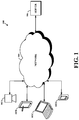
- FIG. 1 shows a simplified block diagram of an example communication network in which at least one embodiment can be implemented.
- FIG. 2 shows a simplified block diagram of a network-access device arranged to implement aspects of at least one embodiment.
- FIG. 3 shows a simplified block diagram of a server arranged to implement aspects of at least one embodiment.
- FIG. 4 depicts an example computer-readable medium arranged to implement aspects of at least one embodiment.
- FIG. 5 is a simplified flow chart depicting aspects of an example method.
- FIG. 6A depicts aspects of a computing device in accordance with one or more example embodiments.
- FIG. 6B depicts aspects of another computing device in accordance with one or more example embodiments.
- FIG. 6C depicts aspects of signals produced from the computing devices in FIGS. 6A and 6B in accordance with one or more example embodiments.
- FIG. 7A depicts aspects of reflection signals associated with a computing device in accordance with one or more example embodiments.
- FIG. 7B depicts aspects of signals indicative of an object in accordance with one or more example embodiments.
- FIG. 7C depicts aspects of artificial signals that simulate the reflection signals in FIG. 7A in accordance with one or more example embodiments.
- FIG. 7D depicts aspects of different signals than the signals in FIG. 7B in accordance with one or more example embodiments.
- FIG. 8A depicts aspects of Beamformed Doppler pulses in accordance with one or more example embodiments.
- FIG. 8B depicts aspects of a variance and Doppler power in accordance with one or more example embodiments.
- FIG. 9 depicts aspects of an abnormal event in accordance with one or more example embodiments.
- FIG. 10 depicts aspects of monitoring pressure of a medium in accordance with one or more example embodiments.
- a computing device may produce detection signals that may be used to detect an object.
- the computing device may produce detection signals from a probe coupled to the computing device.
- the detection signals may penetrate through a medium and reflect off an object in the medium.
- Some of the reflected signals may return to the computing device and/or the probe, or possibly another device coupled to the computing device.
- the reflected signals may be used to detect the presence of the object.
- a computing device positioned outside of a mammal may produce detection signals that penetrate through the mammal's skin, reflect off a kidney stone in the mammal's kidney, and return to the computing device.
- the reflection signals returned to the probe may provide information indicating the presence of the kidney stone in the mammal's kidney.
- the computing device may produce detection signals that excite the object.
- the computing device may produce detection signals, such as excitation pulses, that interact with and/or excite the object.
- excitation pulses may be amplified signals may interact with the object.
- amplified signals may interact with reflection items on the object, such as bubbles inside and/or on the surface of the object.
- the amplified signals may cause the bubbles to get bigger and change shape.
- the excited object may be referred to as a twinkling artifact.
- the computing device may receive reflection signals from an excited object.
- Such reflection signals may be used to detect the excited object.
- such reflection signals may have different characteristics than signals reflected from objects that are not excited. By observing such differences, excited objects may be detected.
- detection signals may be configured to induce the excited state of an object and the reflection signals may detect the excited object.
- characteristics of the detection signals such as amplitude may be configured to induce an excited state of the object.
- various terms referring to respective objects such as a kidney stone, a twinkling artifact, an excited object, and an object induced to an excited state may be used interchangeably, as described herein.
- exciting the object, interacting with a bubble on the object, exciting a bubble on the object, oscillating the bubble on the object, and/or other similar expressions may also be used interchangeably.
- bubbles on an object in the above description are provided for illustrative purposes and should not be construed as limiting. Inducing an excited state of an object may depend on other reflection items as well. For example, cavitation of the object may include impurities where bubbles appear and grow. Further, reflection items may include calcification, crevices, cracks, and/or concretions associated with the object.
- an object may be naturally created in the medium.
- an object may be a kidney stone originated from the accumulation of substances such as minerals and salts in a mammal's kidneys.
- objects may be formed from the clustering of crystals in the mammal's urine.
- objects may also be foreign and/or artificial objects found in the mammal's body. Other possibilities may also exist.
- an indication of the excited object may be provided on an output device (e.g., a graphical display) and the output device may provide further information regarding the excited object.
- harmonic imaging of the object may provide information regarding the location of a kidney stone within the kidney, any movements of the kidney stone within the kidney, characteristics of the kidney stone (e.g., size, shape, and/or composition), among other possibilities.
- FIG. 1 shows a simplified block diagram of an example communication network in which at least one embodiment can be implemented. It should be understood that this and other arrangements described herein are set forth only as examples. Those skilled in the art will appreciate that other arrangements and elements (e.g., medical devices, laboratory machines, interfaces, functions, orders, and groupings of functions, etc.) can be used instead and that some elements may be omitted altogether. Further, many of the elements described herein are functional entities that may be implemented as discrete or distributed components or in conjunction with other components, and in any suitable combination and location. Various functions described herein as being performed by one or more entities may be carried out by hardware, firmware, and/or software. And various functions described herein may be carried out by a processor executing instructions stored in memory.
- example network 100 includes various network-access devices 102 A- 102 D, network 104 such as the Internet, and server 106 .
- network-access devices 102 A, 102 B, 102 C, and 102 D may be a computing device (e.g., a portable medical device), a tablet computer, a laptop computer and/or a desktop personal computer (PC), and a mobile phone, respectively.
- network-access device 102 A may be described as a computing device for carrying out process, methods, and functions further described herein.
- network-access devices 102 B- 102 D, network 104 , and server 106 may be described for purposes of illustrating that various processes, steps, and/or functions may be distributed and performed by other devices, networks, and/or servers.
- network-access devices 102 B- 102 D may be stand-alone devices or may be coupled to network-access device 102 A for carrying out various processes.
- additional entities and devices not depicted in FIG. 1 could be present as well.
- Network 104 may be a public network or a private network (e.g., a local network in a laboratory, a clinic, and/or a doctor's office). As an example, there could be more network-access devices and more servers in communication with network 104 . Other network elements may be in communication with network 104 as well. Also, there could be one or more devices and/or networks making up at least part of one or more of the communication links depicted in FIG. 1 . As an example, there could be one or more routers, switches, or other devices or networks on the communication links between network-access devices 102 A- 102 D, network 104 , and/or server 106 . Each of network-access devices 102 A- 102 D may be any network-access device arranged to carry out the network-access device functions described herein.
- network-access device 102 A may be described as a computing device including an engine capable of producing detection signals and receiving reflection signals. Further, the computing device may be portable, hand-held, and/or transferable by a single person.
- FIG. 2 shows a simplified block diagram of a computing device arranged to implement aspects of at least one embodiment.
- network-access device 102 A may include processor 202 , data storage 204 , and network interface 210 , all linked together via system bus, network, or other connection mechanism 218 .
- Processor 202 may include one or more general purpose microprocessors, central processing units (CPUs), and/or dedicated signal processors.
- processor 202 may include one or more application specific integrated circuits (ASICs), digital signal processors (DSPs), and may be integrated in whole or in part with network interface 210 .
- Data storage 204 may include memory and/or other storage components, such as optical, magnetic, organic or other memory disc storage, which can be volatile and/or non-volatile, internal and/or external, and integrated in whole or in part with processor 202 .
- Data storage 204 may be arranged to contain (i) program instructions 206 and (ii) program logic 208 , executable by processor 202 .
- Data storage 204 may also store data that may be manipulated by processor 202 to carry out the various methods, processes, or functions described herein.
- data storage 204 may include a tangible, non-transitory computer-readable medium, having stored thereon program instructions that, upon execution by one or more processors, cause computing device 102 A to carry out any of the methods, processes, or functions disclosed in this specification or the accompanying drawings.
- program instructions 206 may be maintained in data storage 204 separate from program logic 208 , for easy updating and reference by program logic 208 .
- Network interface 210 may enable network-access device 102 A to send communication and receive communication.
- Network interface 210 typically functions to communicatively couple network-access device 102 A to networks, such as network 104 .
- network interface 210 may include a wired (e.g., Ethernet) and/or wireless (e.g., Wi-Fi, BLUETOOTH®, or a wide-area wireless connection) packet-data interface, for communicating with other devices, entities, and/or networks.
- wired e.g., Ethernet
- wireless e.g., Wi-Fi, BLUETOOTH®, or a wide-area wireless connection
- Input/output function 212 may facilitate user interaction with an example computing device 100 .
- Input/output function 212 may comprise multiple types of input devices, such as a keyboard, a mouse, a touch screen, a probe, a transducer, a sensor, and/or any other device that is capable of receiving input.
- input/output function 212 may comprise multiple types of output devices, such as a graphical display, a printer, one or more light emitting diodes (LEDs), speaker configured to generate audible sounds, or any other device that is capable of providing output discernible to a user.
- example computing device 102 E may support remote access from another device, via network interface 210 or via another interface (not shown), such an RS-132 or Universal Serial Bus (USB) port.
- USB Universal Serial Bus
- Probe 214 may produce one or more radio frequency pulses, radio frequency pulses produced within a first time period (e.g., 333 microseconds), a sequence of substantially similar radio frequency pulses produced within a time period different than the first time period, a sound wave, a sound pressure wave, and/or an oscillating sound pressure wave.
- the first time period may be 200-400 microseconds, among other possible ranges.
- probe 214 may produce such pulses in response to executing program instructions 206 stored in data storage 204 and communicating to probe 214 via other connection mechanism 218 .
- Probe 214 may also produce signals within one or more time periods.
- any one of the signals may be produced within a given time period and other detection signals may be produced within a different time period.
- probe 214 may produce, ultrasound propagation or arrays, Doppler signals, among other possibilities.
- probe 214 may produce one or more pulses that contain a series of 10-30 identical pulses or bursts, 1-10 cycles of such bursts, and where the pulses are transmitted with a central frequency of 2 to 8 MHz.
- the pulses may have a 1-5 kHz pulse-repetition frequency (PRF).
- PRF pulse-repetition frequency
- probe 214 may produce detection signals such as excitation pulses. Further, in some instances, detection signals may have 2 to 5 cycles. Yet further, in some instances, positive pressures (P+) and negative pressures (P ⁇ ) of pressure detections signals may be 1 to 5 MPa and ⁇ 5 to ⁇ 1 MPa, respectively. Probe 214 may also receive signals reflected from external objects back to probe 214 . Computing device 100 may also receive signals through a sensor or another device, possibly connected through input/output function 212 . As noted, detection signals may be configured to induce an excited state of an object. As such, it should be understood that the above-characteristics of detection signals may be configured to induce the excited state of an object.
- probe 214 may be removable so as to operate while being physically separate from computing device 100 .
- probe 214 may communicate remotely with computing device 110 through input/output function 212 .
- Reflected signals received by probe 214 may be converted to digital signals through analog-to-digital converter (ADC) 216 .
- ADC 216 may be a 12-24 bit analog-to-digital converter configured to sample signals at a 10-30 MHz frequency.
- signals transmitted by probe 214 may be received by probe 214 and converted to digital signals through ADC 216 .
- digitized signals from ADC 216 may also be processed in real-time using mathematical software platforms.
- unmodified signal outputs from ADC 216 may identify characteristics of objects for detecting the objects.
- computing device 102 A may also include one or more digital-to-analog converters (not illustrated) that may be configured to transmit signals to probe 214 . As such, probe 214 may produce detection signals as described herein.
- computing device 102 A may modify the reflected signals received by probe 214 .
- signals may be modified by band-pass filters, analog filters, amplifiers, and clipping diodes (not shown in FIG. 2 ).
- signals may be modified by an anti-aliasing band-pass filter with a 0.7 to 17 MHz bandwidth.
- signals may be amplified using time-gain compensation.
- signals may be limited and/or clipped by a diode.
- the modification described herein may be implemented through signal processing software. It should be noted that the above-referenced modifications to the reflected signals may occur before being sampled by ADC 216 .
- Server 106 may be any network server or other computing system arranged to carry out the server functions described herein including, but not limited to, those functions described with respect to FIGS. 5-10 .
- reflection signal received by probe 214 may be communicated to server 106 for analysis, possibly to detect an excited object.
- network-access device 102 A and server 106 may share processes, methods, and/or functions described herein for determining the presence of the excited object.
- FIG. 3 shows a simplified block diagram of a server arranged to implement aspects of at least one embodiment. As such, as shown in FIG.
- server 106 may include processor 302 , data storage 304 including program data 306 and program logic 308 , and network interface 310 , all linked together via system bus, network, and/or other connection mechanism 312 .
- Processor 302 , data storage 304 , program data 306 , program logic 308 , and network interface 310 may be configured and/or arranged similar to processor 202 , data storage 204 , program instructions 206 , program logic 208 , and network interface 210 , respectively, as described above with respect to network-access device 102 A.
- Data storage 304 may contain information used by server 106 in operation.
- date storage 304 may include instructions executable by the processor for carrying out the server functions described herein including, but not limited to, those functions described below with respect to FIGS. 5-10 .
- data storage 304 may contain various design logic and/or design data used for determining a test result, such as the logic and data described below with respect to FIGS. 5-10 .
- data storage 304 may contain information used by server 106 to provide information accessible by various network-access devices, such as network-access device 102 A, over network 104 .
- network 104 may also include one or more wide area networks, one or more local area networks, one or more public networks such as the Internet, one or more private networks, wired networks, wireless networks, and/or networks of any other variety.
- Devices in communication with network 104 may exchange data using a packet-switched protocol such as IP, and may be identified by an address such as an IP address.
- IP packet-switched protocol
- FIG. 4 is a schematic illustrating a conceptual partial view of an example computer program product that includes a computer program for executing a computer process on a network-access device, arranged according to at least some embodiments presented herein.
- the example computer program product 400 is provided using a signal bearing medium 402 .
- the signal bearing medium 402 may include one or more programming instructions 404 that, when executed by one or more processors may provide functionality or portions of the functionality described herein.
- the signal bearing medium 402 may encompass a computer-readable medium 406 , such as, but not limited to, a hard disk drive, a Compact Disc (CD), a Digital Video Disk (DVD), a digital tape, memory, etc.
- the signal bearing medium 402 may encompass a computer recordable medium 408 , such as, but not limited to, memory, read/write (R/W) CDs, R/W DVDs, etc.
- the signal bearing medium 402 may encompass a communications medium 410 , such as, but not limited to, a digital and/or an analog communication medium (e.g., a fiber optic cable, a waveguide, a wired communications link, a wireless communication link, etc.).
- a communications medium 410 such as, but not limited to, a digital and/or an analog communication medium (e.g., a fiber optic cable, a waveguide, a wired communications link, a wireless communication link, etc.).
- the signal bearing medium 402 may be conveyed by a wireless form of the communications medium 410 .
- computer-readable medium 406 , computer recordable medium 408 , and communications medium 410 as contemplated herein are distinct mediums and that, in any event, computer-readable medium 408 is a physical, non-transitory, computer-readable medium.
- the one or more programming instructions 404 may be, for example, computer executable and/or logic implemented instructions.
- a computing device such as the network-access device 102 A of FIG. 2 may be configured to provide various operations, functions, or actions in response to the programming instructions 404 conveyed to the network-access device 102 A by one or more of the computer readable medium 406 , the computer recordable medium 408 , and/or the communications medium 410 .
- the physical and/or non-transitory computer readable medium could also be distributed among multiple data storage elements, which could be remotely located from each other.
- the computing device that executes some or all of the stored instructions could be a network-access device such as the network-access device 102 A illustrated in FIG. 2 .
- the computing device that executes some or all of the stored instructions could be another computing device, such as a server, for instance server 106 illustrated in FIG. 3 .
- FIG. 5 shows a simplified flow chart depicting aspects of an example method for detecting an object as described herein.
- aspects of such example methods are described with reference to an example computing device. It should be understood, however, that the example methods described herein may apply just as well to any suitable computing device including, but not limited to, a computing device integrated with a computer, a mobile computing device, a medical device, and/or other computing system, among other examples.
- FIGS. 6A and 6B depict aspects of example computing devices in accordance with one or more example embodiments. More particularly, FIGS. 6A and 6B depict aspects of a computing device illustrated in FIG. 5 for carrying out the method for detecting an object. For example, computing device 602 depicts aspects of an example computing device detecting an object. Various respective features, characteristics, and/or functionality of the computing devices depicted in FIGS. 6A and 6B are discussed further below with respect to the example methods described herein.
- method 500 is described by way of example as being carried out by a computing device, possibly a computing device coupled to a probe.
- method 500 may be carried by network-access device 102 and/or computing device 602 .
- example methods, such as method 500 can be carried out by devices other than a computing device and/or can be carried out by sub-systems in a computing device.
- method 500 may also be carried out by network-access devices 102 B- 102 D, network 104 , and/or server 106 .
- an example method can be carried out by a computing device which is programmed to display an excited object on a graphical display.
- method 500 begins at block 502 with a computing device, such a computing device coupled to a probe, which may carry out functions for producing one or more detection signals configured to induce an excited state of an object.
- a computing device such a computing device coupled to a probe, which may carry out functions for producing one or more detection signals configured to induce an excited state of an object.
- the computing device receives one or more reflection signals, where the reflection signals correspond to at least one of the detection signals reflected from the object.
- the computing device determines a presence of the object in the excited state.
- the computing device causes an output device to provide an indication of the presence of the object in the excited state.
- method 500 may be carried out by network-access device 102 A, this is not required. Various steps illustrated by these flow charts may be carried out by other types of devices or systems, such as server 106 . Further, it may be possible to distribute aspects of individual steps between network-access devices 102 A- 102 B, network 104 , and server 106 . For instance, network-access device 102 A may produce detection signals and receive reflection signals and server 106 may determine the presence of the object in the excited state.
- FIGS. 6A and 6B depict aspects of example computing devices in accordance with one or more example embodiments.
- FIG. 6A depicts aspects of a computing device in accordance with one or more example embodiments.
- scenario 600 provides a computing device 602 that may be positioned adjacent to medium 604 .
- computing device 602 may be similar as computing device 102 A in FIGS. 1 and 2 .
- computing device 602 may be configured to communicate with other computing devices, such as another computing device described in further detail in FIG. 6B .
- medium 604 may be part of a human body or an organ encompassing object 610 .
- object 610 may be a kidney stone that may be 1 to 15 mm in diameter and medium 604 may be a kidney.
- object 610 may be a foreign object (e.g., a bullet from a handgun, a catheter, or a stent), a gall stone, a salivary duct stone, tissue, a blood vessel, plaque, and/or a bone fragment, among other possibilities.
- object 610 may be a mass or a buildup of minerals, such as a concretion, for example.
- Other examples of mediums and objects may exist.
- object 610 may include reflection items that may be used to help detect the presence of object 610 in medium 604 .
- reflection items may include a bubble, a calcification, a crevice, a crack, and/or a concretion associated with the object.
- a reflection item may be bubble 612 on object 610 .
- bubble 612 may be in a crack and/or crevice of object 610 .
- bubbles may also be formed in free fluid, concretions, and/or tissues in a mammal.
- bubble 610 may be formed on any of the example objects described above for object 610 .
- a bubble, such as bubble 612 may include trapped air, a gas pocket, and/or air emboli.
- bubble 612 may be stationary or in motion while on the surface of object 610 .
- bubble 612 is illustrated in FIG. 6A as a growing bubble.
- the dotted lines in FIG. 6A illustrate that bubble 612 has grows from a smaller bubble to the current size illustrated by the solid line surrounding the dotted lines.
- the dotted lines may resemble the outer surface of bubble 612 as it grows.
- detection signals may interact with bubble 612 , causing it to grow.
- detection signals may interact with bubble 612 to drive it into instability.
- the detection signals may vary the size and/or shape of bubble 612 and change the properties of bubble 612 to detect the reflective properties of bubble 612 , as described further with respect to block 506 of FIG. 5 .
- FIG. 6B depicts aspects of another computing device in accordance with one or more example embodiments.
- scenario 650 provides a computing device 660 that may be positioned adjacent to medium 664 .
- computing device 660 may be similar to computing device 102 A and/or computing device 602 .
- medium 664 may be a human body or the body of some other living mammal.
- object 670 may be similar to object 610 and bubble 672 may be similar to bubble 612 .
- bubble 672 may also be a growing bubble.
- object 670 may be a kidney stone that is 5-12 mm in diameter with reflection items to detect the presence of object 670 in medium 664 .
- a computing device may carry out functions for producing one or more detection signals configured to induce an excited state of an object.
- computing device 602 may produce detection signals.
- computing device 602 may produce pulses in a direction 606 toward medium 604 and object 610 .
- computing device 602 may produce pulses that penetrate the surface of medium 604 and reflect off of object 610 .
- computing device 602 may increase or decrease the amplitude of detection signals to interact with bubble 612 on object 610 and induce an excited state of object 610 .
- the detection signals may drive bubble 612 into oscillation and/or instability.
- computing device 602 may produce detection signals that are focused on a region of object. In some instances, detection signals may be focused on a reflection item. For example, computing device 602 may produce detection signals focused or directed to bubble 612 . For instance, referring back to FIG. 2 , detection signals may be focused or directed toward a given bubble by positioning probe 214 in a given manner. In some instances, probe 214 may be angled in such a way to direct detection signals towards the given bubble. As such, the detection signals may be focused on the left side of bubble 612 . In some instances, detection signals may be directed towards the left side of bubble 612 and then the signals may be directed towards to the right side of bubble 612 . Other possibilities may also exist.
- computing devices 602 and 660 may produce different types of detection signals.
- FIG. 6C depicts aspects of signals produced from the computing devices 602 and 660 in FIGS. 6A and 6B , respectively, in accordance with one or more example embodiments.
- signal 680 may be a Doppler signal with a multiple pulses.
- signal 682 may be a B-mode with plane waves.
- signal 684 may be a pulse sequence with peak positive pressures (P+) and peak negative pressures (P ⁇ ).
- signal 686 may be a shock wave pulse.
- detection signals may include one or more bursts such that each burst includes a number of pulses. For example, as illustrated by signal 680 , a single burst may include 14 pulses. It should be noted that signal 680 may also have one or more of cycles such that each cycle includes a burst and a time period before or after the burst. In particular, signal 680 may have a 160 microsecond cycle with a burst of 5 microseconds. As such, 155 microseconds may be a time period after the burst. It should be noted that detection signals may include a range of 7 to 21 bursts. Yet further, detection signals may include 2 to 7 cycles of bursts and time periods without bursts.
- Doppler mode may be used produce signal 680 .
- signal 680 may include 14 identical pulses such that the pulses are produced consecutively by a probe and/or a transducer (such as probe 214 ).
- Doppler mode may be implemented to produce the 14 pulses in signal 680 .
- such pulses may be produced with a 3 kHz pulse-repetition frequency (PRF).
- PRF pulse-repetition frequency
- the PRF may be adjusted and/or modified according to the dimensions of object 610 and/or bubble 612 .
- signal 680 may have varying amplitudes to provide an initial excitation pulse with greater amplitudes followed by lower amplitude pulses.
- B-mode may be used to produce signal 682 .
- signal 682 may include a series of plane waves.
- signal 682 may include a one micro-second plane wave in a 160 micro-second cycle. It should be understood that B-mode may be implemented to produce the plane waves in signal 682 .
- a Push mode may produce signal 684 . As illustrated, signal 684 may include a 3 millisecond cycle with a burst of pulses over a 100 microseconds.
- a Shock mode may produce 686 .
- Signal 686 may have characteristics similar, in some respects, to signals produced by lithotripters for breaking up object 610 .
- computing devices 602 and 606 are not the same as conventional lithotripters. As described above, computing device 602 and 606 may produce a variety of different signals, including those produced by lithotripters.
- detection signals may include pressure waveforms, possibly excitation signals and/or pulses.
- signal 684 may have positive pressures (P+) and negative pressures (P ⁇ ) of pressure waveforms. In some instances, signal 684 may also be re-produced in three cycles and a central frequency of 5 MHz. In some instances, positive pressures and negative pressures of signal 684 may be 2 MPa and ⁇ 1 MPa, respectively. As such, signal 684 may excite object 670 such that bubble 672 in and/or on object 670 grows with each signal interacting with bubble 672 . It should be noted that the positive and negative pressures of signals 684 may be adjusted. In particular, the pressures may be raised to drive bubble 672 into oscillation. Further, in some instances, the pressures may be lowered to prevent saturation of the oscillation effect.
- a variation of the different signals may be produced.
- signal 684 may be produced to interact with bubble 672 , possibly driving bubble 672 into oscillation.
- signal 680 may be produced and reflection signals may be received to indicate the presence of object 670 .
- the reflection signals may include phase variations or phase variability indicative of the presence of object 670 .
- the presence of object 670 may be determined.
- signal 686 may be produced to break object 670 into fragments.
- signal 684 may be produced to oscillate bubbles on object 670 and signal 680 may be produced to receive reflection signals indicative of the presence of object 670 .
- Other possibilities may also exist.
- detection signals may be produced and directed to a human body.
- computing device 660 may produce detection signals in a direction 666 toward medium 664 and object 670 .
- computing device 660 may produce pulses that penetrate the surface of medium 664 to reflect off of object 670 , possibly returning in a direction 668 toward computing device 660 .
- detection signals may be configured to induce an excited state of an object.
- computing device 660 may produce detection signals configured to induce an excited state of object 670 .
- computing device 660 may produce amplified signals that interact stochastically with bubble 672 on object 670 , possibly driving bubble 672 into oscillation. It should be noted that detection signals with certain characteristics described above may excite object 670 .
- the negative pressure phases of the detection signals produced by computing device 660 may induce an excited state of object 670 .
- negative pressure phases may create tension that oscillates bubble 672 .
- bubble 672 may be in the bulk of object 670 and/or on the surface of object 670 .
- detection signals may excite bubble 672 in the bulk of object 670 or cracks inside object 670 .
- detection signals may interact with internal calcifications in object 670 to produce an excited state of object 670 .
- detection signals may excite bubble 672 on the surface of object 670 , particularly if there are microscopic crevices on the surface of object 670 .
- detection signals may induce an excited state of object 670 when there are gas pockets on the surface of object 670 .
- bubbles such as bubble 672 may be micron or submicron size so as to be invisible and detectable only by inducing the excited state of object 670 .
- the computing device receives one or more reflection signals, where the reflection signals correspond to at least one of the detection signals reflected from the object.
- computing device 602 may produce detection signals in a direction 606 toward medium 604 and object 610 .
- the reflected signals may return in a direction 608 toward computing device 602 so as to be received by computing device 602 .
- computing device 602 may be placed 5-15 centimeters away from medium 604 when sending and receiving pulses and in other instances, computing device 602 may be farther away from, or closer to, medium 604 . In other instances, computing device 602 may make contact with the outer surface of medium 604 when sending and receiving pulses.
- FIG. 6B illustrates reflected signals returning in a direction 668 toward computing device 660 .
- reflection signals may indicate the presence of bubble 672 , possibly indicating the presence of object 670 .
- one or more pressure waveforms produced by computing device 660 may be measured by a hydrophone associated with computing device 660 , possibly integrated within computing device 660 . In other instances, the waveforms produced by computing device 660 may be measured by a broadband hydrophone having a sensitivity of 48 nV/PA at 5 MHz.
- the computing device determines a presence of the object in the excited state.
- computing devices 602 and 660 may receive reflection signals after exciting bubbles 612 and 672 , respectively.
- computing devices may determine the presence of exited object by analyzing the reflection signals.
- reflection signals from an excited object may have different characteristics than signals reflected from objects that are not excited. Such differences may help, facilitate, and/or aid in detecting the excited object.
- various measurements of the reflection signals may indicate the presence of an excited object. For example, a variance in the reflection signals may be measured to determine the excited object.
- bubbles may be driven into oscillation and the oscillation may be determined by measuring phase variability, amplitude, and/or harmonics associated with the reflection signals. Thus, by determining the oscillation, the presence of the object and/or the bubble in the excited state may be determined. Additional examples of determining an object in the excited state are described below.
- an object in the excited state may be determined by analyzing reflection signals.
- FIG. 7A depicts aspects of reflection signals associated with a computing device in accordance with one or more example embodiments. Further, FIG. 7A may illustrate reflection signals including 12 signals, signals 701 - 712 .
- signals 701 - 712 may be reflection signals reflected from an excited object and received by a computing device. The signals may be measured by amplitude on the y-axis and time on the x-axis, with sample rate of 50 nanoseconds per sampling point.
- signals 701 - 712 may be represented on the same graph in FIG. 7A such that each signal overlaps one another. It should be noted that signals 701 - 712 may have similar characteristics such that overlapping the signals over one another creates the appearance of a single signal in FIG. 7A .
- the power of signals may be used to determine the presence of the excited object.
- Doppler power calculated from Doppler signals may be used to identify an object.
- FIG. 7B depicts aspects of signals indicative of an excited object in accordance with one or more example embodiments. In particular, FIG. 7B illustrates the power of the signals illustrated in FIG. 7A . Further, FIG. 7B illustrates Doppler power calculated on a decibel scale (dB) on the y-axis and time on the x-axis, with a sampling rate of 50 nanoseconds per sampling point.
- dB decibel scale
- a spike in the data occurs approximately 2-3 microseconds after receiving signals reflected off the excited object.
- such spikes indicate that portions of pulses in FIG. 7A fluctuate from pulse to pulse.
- Such spikes in power, or fluctuations from pulse to pulse may be used to determine the presence of an excited object. It should be noted that the Doppler power may be calculated relative to the background noise level.
- computing devices 602 and 660 may determine that an excited object is not present. For example, computing devices may make such determinations based on receiving artificial signals simulating those of reflection signals.
- FIG. 7C depicts aspects of artificial signals that simulate the reflection signals in FIG. 7A in accordance with one or more example embodiments. Further, FIG. 7C may illustrate artificial signals including 12 signals, signals 721 - 732 .
- signals 721 - 732 may be produced by a waveform generator and received by a computing device. The signals may be measured by amplitude on the y-axis and time on the x-axis, with sample points at 50 nanoseconds per sampling point. As illustrated, signals 721 - 732 may be represented on the same graph in FIG.
- signals 721 - 732 may have similar characteristics such that overlapping the signals over one another creates the appearance of a single signal in FIG. 7C . It should be noted that signals 721 - 732 may be produced using a mathematical modeling software and a function generator.
- FIG. 7D depicts aspects of different signals than those in FIG. 7B in accordance with one or more example embodiments.
- FIG. 7D illustrates the power of the simulated signals illustrated in FIG. 7C .
- FIG. 7D illustrates Doppler power calculated on a decibel scale (dB) on the y-axis and time on the x-axis. Further, the Doppler power may also be calculated relative to the background noise level.
- dB decibel scale
- the Doppler power may also be calculated relative to the background noise level.
- an excited object may be detected without signal processing.
- FIG. 7B illustrates detecting the excited object without signal processing.
- FIG. 7B illustrates the excited object based on signals output from an analog-to-digital converter (ADC) of the computing device, possibly ADC 216 in FIG. 2 .
- ADC analog-to-digital converter
- the excited object may be based on raw RF data from ADC 216 and not from signal processing of the RF data.
- the excited object may be detected from reflection signals (e.g., raw RF data) and not from artificial signals mimicking reflection signals.
- the excited object may be identified solely by the RF data signals received by the computing device, without any signal processing of the reflection signals.
- various modes for producing detection signals may be used to determine an excited object.
- computing devices may determine the presence of an object using the various modes for producing the detection signals.
- Doppler mode and B-mode may be employed to produce detection signals.
- reflection signals may be received and processed accordingly by the analog-to-digital converter, such as ADC 216 .
- ADC 216 the analog-to-digital converter
- such signals may determine a presence of object 610 in the excited state.
- digital signals output from the ADC 216 may further be filtered, amplified, and/or clipped through further signal processing and the presence of excited object 610 may be determined.
- spikes in amplitude of reflection signals may be used to determine an excited object.
- FIG. 8A depicts aspects of Beamformed Doppler pulses in accordance with one or more example embodiments.
- FIG. 8B depicts aspects of a variance (e.g., phase variability of one or more reflection signals) and Doppler power in accordance with one or more example embodiments.
- residual amplitudes may be measured on the y-axis and imaging depth may be measured on the x-axis.
- residual amplitudes may vary from pulse to pulse.
- some pulses in area 802 show spikes in residual amplitude which occur at the same depth as the spike in the corresponding Doppler power, indicating the presence of an excited object.
- area 802 of FIG. 8A corresponds to the spike in the Doppler power in FIG. 8B for detecting an excited object.
- the variance may determine the presence of the excited object.
- the Doppler power may be calculated based on the residual amplitude. As such, the Doppler power may be calculated to determine the presence of an excited object. For example, the residual amplitude A nm , may be calculated for each Doppler pulse within a series of Doppler pulses. Further, Doppler power W m may be calculated by the following equation:
- calculating the Doppler power using the equation above may determine the presence of an excited object found in a given medium.
- the appearance of a spike in residual amplitude may be considered an “abnormal event,” indicating the presence of an excited object.
- a maximum residual amplitude or a threshold amplitude may be determined for reflection signals.
- the maximum residual amplitude for a series of pulses may be 3 dB over the averaged maximum residual amplitude for the series of pulses.
- FIG. 9 depicts aspects of an abnormal event in accordance with one or more example embodiments. As illustrated in FIG. 9 , the amplitudes of twelve pulses are measured on the y-axis and the imaging depth is measured on the x-axis. The distribution of the amplitude may show that the abnormal event appears uniformly over all the pulses in the series of pulses, indicating the presence of an excited object.
- a threshold may be applied to determine the presence of an excited object.
- threshold 902 may be applied to the amplitudes in FIG. 9 .
- an amplitude that exceeds threshold 902 may determine the presence of an excited object.
- thresholds such as threshold 902
- FIGS. 7B, 8A, and 8B may be applied to FIGS. 7B, 8A, and 8B in a similar manner to determine an excited object.
- thresholds may not be linear as shown with threshold 902 .
- thresholds may take the form of a function and may also change dynamically with respect to different signals and amplitudes.
- signal processing may be used to display an image of the excited object.
- B-mode images combined with Doppler-mode images may be generated to display an excited object.
- images may be generated using signal processing algorithms that utilize Doppler thresholds.
- color information of reflected signals may be based on a comparison between the Doppler power of reflected signals and a Doppler power threshold or a maximum Doppler power.
- the maximum Doppler power may be decreased to a minimum level (e.g., a level just above the level background noise.)
- color-write priority may be set to the highest level such that color information, rather than the B-mode information, may always be plotted on a graphical display. Further examples of displaying an excited object is described for block 508 of FIG. 5 below.
- signal processing may involve a numerical computation environment to determine the presence of an excited object.
- the signal processing may be based on mathematical codes and/or computational algorithms.
- characteristics of reflection signals may be calculated and these characteristics may indicate a presence of the excited object.
- the Doppler residual and Doppler power may be characteristics that may be calculated by a numerical computation environment to determine an excited object.
- reflected signals may be received uniformly and no Doppler shift may be determined.
- any differences from pulse to pulse may be determined in the above-referenced equation, possibly determining the presence of an excited object.
- U n ((t ⁇ nT) for different n pulses may indicate pulses reflecting off an object and arriving to the computing device with a time shift.
- a velocity of an object may be calculated from the time shift, possibly indicating the presence of an excited object.
- U n (t) may not indicate the time shift, but may instead indicate a fluctuation based on the reflections signals. In such instances, a velocity of the object may also be calculated such that the presence of the excited object may be determined.
- additional signal processing may be implemented to determine the presence of an excited object.
- wall filtering may be used to determine a presence of an excited object.
- wall filter may be used to reduce signal fluctuations of the reflection signals, possibly due to slow-moving reflection signals.
- a first order regression filter may be applied to the analytic signal V nm .
- the corresponding signals from different pulses within the reflection signals may be considered as a function of the n pulses.
- V nm a m +n b m .
- the expression may provide for V nm using a least squares estimation (where a m and b m may be some coefficients that do not depend on the pulse number n.)
- a nm may be used to detect fluctuations in the reflection signals to determine the presence of an excited object.
- calculating the Doppler power may determine the presences of an excited object found in a given medium.
- computing device 660 may send detection signals and receive reflection signals from excited object 670 . Further, computing device 660 may communicate with server 652 through communication link 658 such that server 652 may determine the excited object (e.g., determining the Doppler power of the reflection signals). In addition, server 652 may communicate with computer 656 through communication link 654 such that server 652 and computer 656 may share processes for determining the excited object. In some instances, computing device 660 may communicate with computer 656 through communication link 662 such that computer 656 may determine the excited object (e.g., provide a graphical display of the Doppler power). Other possibilities may also exist.
- communication links 658 , 654 , and 662 may be physically wired communication links such as serial bus connections and/or parallel bus connections.
- these communication links may be wireless communications, e.g., Bluetooth® radio technology, Cellular technology (such as GSM, CDMA, or WiMAX), or Zigbee® technology, among other possibilities.
- the computing device causes an output device to provide an indication of the presence of the object in the excited state.
- a computing device may communicate with one or more other computing devices to display an indication of the object in the excited state.
- computing device 660 may communicate with computer 656 to display characteristics of object 670 .
- computer 656 may display data indicative of the material surrounding object 670 , the size of object 670 , the position of object 670 (e.g., coordinates in a three-dimensional layout), among other possibilities.
- computer 656 may provide information indicating of the presence of object 670 in medium 664 .
- computer 656 may provide graphical representations indicating the presence of object 670 in medium 664 .
- computer 656 may display a harmonic image of object 670 in the excited state.
- computer 656 may include a speaker to generate an audible sound corresponding to one or more detection signals, possibly indicative of detecting object 670 .
- computer 656 is illustrated as a laptop computer, computer 656 may also be a smaller computing device such as network-access device 102 D, for example. Yet further, it should be noted that various embodiments described herein may be combined or interchangeable. For example, a smaller version of the graphical display on computer 656 may be incorporated with computing device 660 to display the characteristics of object 670 and to detect the presence of object 670 . Other possibilities may also exist.
- a pressure within a medium encompassing the object may be determined. In some instances, determining the pressure of the medium may aid, facilitate, and/or help to detect the object within the medium. For example, reducing the static pressure in the medium may help to reduce any suppression of twinkling or excitation such that the object may be detected. It should be noted that the examples below are provided for purposes of illustration and should not be interpreted as limiting. For example, one or more of the processes, methods, and/or functions below may be performed or similarly performed on a mammal, such as a human.
- FIG. 10 illustrates monitoring pressure of a medium, according to an example embodiment.
- transducer 1002 e.g., a probe
- transducer 1002 may be placed in water tank 1004 and above high pressure chamber 1004 .
- transducer 1002 may be the same transducer as probe 214 in FIG. 2 .
- High pressure chamber 1006 may be cylindrical in shape with an inner diameter of 11.2 cm and a height of 7 cm.
- High pressure chamber 1006 may have walls, a bottom, and upper lid made of aluminum. The walls may be 4.5 cm thick, and the bottom and the lid may be 3.6 cm thick, to sustain high pressures.
- absorber 1008 may be a 1 cm thick acoustic rubber placed on the bottom of high pressure chamber 1006 to dampen possible reverberations during stone imaging.
- Stone 1010 may be immersed in water 1012 and fixed on the tip of a brass needle 1.6 mm in diameter that is attached to a wall of high pressure chamber 1006 by stone holder 1016 .
- Acoustic window 1014 may be a polystyrene puck fixed in the middle of the lid to serve as an acoustic window for better ultrasound transmission.
- a plastic cylinder of 8.8 cm diameter and 5.1 cm height may be attached to form an external water tank, where transducer 1002 may immersed.
- Transducer 1002 may be fixed on the positioning system with its axis oriented perpendicularly to the lid of high pressure chamber 1004 .
- the surface of the transducer 1002 may be close (less than 1 mm) but may not touch acoustic window 1014 during experimentation. As such, transducer displacement caused by acoustic window 1014 bending under high-pressure may be prevented.
- the transversal position of transducer 1002 may be adjusted by the positioning system to find the optimal location on the stone for detecting the excited characteristics.
- high static pressure may be generated inside high pressure chamber 1004 by a piston screw pump (not shown in FIG. 10 ).
- This pump may be capable of producing pressure up to 200 MPa.
- lower pressures (less than 9 MPa) may be used since higher pressures may exceed several times the peak negative pressure of the ultrasound pulses.
- a gauge of maximum scale of 13.8 MPa may be used for determining pressure in high pressure chamber 1005 .
- Doppler imaging may illustrate that pressure in high pressure chamber 1006 may suppress the twinkling or excitation of stone 1010 .
- the high pressure applied may suppress the twinkling or excitation of stone 1010 almost completely. Further, by releasing the pressure, the twinkling or excitation of stone 1010 may reappear immediately.
- a pressure threshold may be determined for detecting an excited object. For example, the pressure of high pressure chamber 1006 may be monitored such that if the pressure exceeds the pressure threshold for detecting stone 1010 , an indication may be provided.
- a pressure threshold may vary from 0.34 MPa to 1.38 MPa under conditions shown in FIG. 10 . Further, in some instances the pressure threshold may be 0.34 MPa to 1.72 MPa. As such, the pressure threshold may vary according to different stones and/or different conditions.
- monitoring the pressure of a medium encompassing a stone may determine the positive and negative pressures for a transducer.
- positive pressures (P+) and negative pressures (P ⁇ ) of pressure detections signals may be 2 MPa and ⁇ 1 MPa, respectively, to induce an excited state of an object.
- P+ and negative pressures (P ⁇ ) of pressure detections signals may be 2 MPa and ⁇ 1 MPa, respectively, to induce an excited state of an object.
- the pressure of a medium encompassing the stone may be monitored and used to produce detection signals to induce the excited state of stone 1010 .
- Real human kidney stones were either embedded in a degassed gel block, or in degassed water.
- the human kidney stones consisted of more than 90% calcium oxalate monohydrate and were 5-12 mm in diameter with submicron bubbles trapped in crevices on the stone surface.
- the kidney stones were placed in gel and in water.
- the gel used was polyacrylamide hydrogel, which mimicked tissue structure.
- the liquid mixture was first degassed for at least one hour in a desiccant chamber before commencing experimentations.
- the ultrasound engine was used to determine the presence of the kidney stone.
- the ultrasound engine achieved the results below by utilizing a 128 element linear ultrasound array with a 5 MHz central frequency with a clinical probe.
- the reflection signals were received by a broadband calibrated hydrophone with a sensitivity of 48 nV/Pa at 5 MHz.
- the acoustic pulse was similar to the transducer voltage with a form of a 3-cycle tone burst with a central frequency of 5 MHz.
- the kidney stones were positioned 4 cm from the ultrasound probe and were immersed within the tissue-mimicking gel. At the location 4 cm away from the transducer in water, the measured peak positive and negative pressures were 2 MPa and ⁇ 1 MPa, respectively. These values aided choosing sufficiently high levels of the static pressure in an overpressure test.
- the imaging was performed in a “flash” transmitting mode when all the array elements were excited simultaneously to emit a quasi-plane wave in the direction orthogonal to the radiating surface (zero degrees incident angle). Such a mode simplified the analysis of the reflection signals without limiting the possibility of stone imaging. Both B-mode and Doppler mode were employed.
- the array elements were excited by a series of 14 identical pulses emitted one-after-another with 3 kHz pulse-repetition frequency (PRF).
- PRF pulse-repetition frequency
- the PRF was adjustable.
- Each pulse in the 14 pulse was a tone burst consisting of three cycles at the central frequency 5 MHz.
- the reflection signals were received when the detection signals reflected from the kidney stone and returned to the probe.
- the corresponding reflection signals of the array elements went through an anti-aliasing band-pass filter of 0.7-17 MHz bandwidth, an amplifier with the time-gain compensating (TGC) feature, a clipping diode (to limit excessive signals), and were sampled at a 20 MHz frequency by a 12-bit analog-to-digital convertor (ADC).
- the digitized signals were processed in real-time using in-house code written in a mathematical software platform.
- the signals were also stored in a buffer and were able to be post-processed at a later time.
- the saved signals were radio-frequency (RF) data output from the ADC's for each channel. Access to this RF data provided a possibility to study the “raw” ultrasound signals associated with the excited kidney stone.
- RF radio-frequency
- FIG. 7A shows typical signals that were analyzed to reveal the features of the excited kidney stone.
- FIGS. 7A and 7B describe data for imaging the natural kidney stones, which were placed in the gel.
- FIG. 7A overlays 12 successive reflection signals 701 - 712 of the Doppler ultrasound pulses reflected from the stone and recorded at the central element of the array.
- the signals 701 - 712 that were plotted on top of each other are barely distinguishable, because the corresponding changes are small.
- the Doppler power was calculated from those waveforms.
- the Doppler power is shown in FIG. 7B .
- the Doppler power was provided on a dB scale, relative to the background noise level.
- the essential spike occurred about 2-3 microseconds after the arrival of the front of the reflection signals 701 - 712 , which indicated that the corresponding part of the signal within the Doppler signal was fluctuating from pulse to pulse.
- Such a spike was observed for all studied stones and corresponded to exciting the kidney stone of the color Doppler image. This illustrated detecting the excited kidney stones.
- FIG. 7C shows signals obtained for a simulated acoustic source test.
- the simulated Doppler signals shown in FIG. 7C provide 12 signals that were plotted on top of each other.
- the signals in FIGS. 7C and 7D were visually identical, which indicated a high quality of the mimicking procedure.
- the artificial Doppler signals 721 - 732 were sent through the same signal path inside the machine as the signals 701 - 712 .
- FIG. 7D represents the result for the Doppler power calculated from the signals 721 - 732 . No obvious spike was seen, as shown in FIG. 7D . This test was repeated for six kidney stones, and the result was repeatable. This observation provided the conclusion that the origin for determining the presence of an excited kidney stone is not related to a machine or signal processing. Therefore, detecting the excited kidney stone resulted from an acoustic effect.
- each block and/or communication can represent a processing of information and/or a transmission of information in accordance with example embodiments.
- Alternative embodiments are included within the scope of these example embodiments.
- functions described as blocks, transmissions, communications, requests, responses, and/or messages can be executed out of order from that shown or discussed, including substantially concurrent or in reverse order, depending on the functionality involved.
- more or fewer blocks and/or functions can be used with any of the ladder diagrams, scenarios, and flow charts discussed herein, and these ladder diagrams, scenarios, and flow charts can be combined with one another, in part or in whole.
- a block that represents a processing of information can correspond to circuitry that can be configured to perform the specific logical functions of a herein-described method or technique.
- a block that represents a processing of information can correspond to a module, a segment, or a portion of program code (including related data).
- the program code can include one or more instructions executable by a processor for implementing specific logical functions or actions in the method or technique.
- the program code and/or related data can be stored on any type of computer readable medium such as a storage device including a disk or hard drive or other storage medium.
- the computer readable medium can also include physical and/or non-transitory computer readable media such as computer-readable media that stores data for short periods of time like register memory, processor cache, and random access memory (RAM).
- the computer readable media can also include physical and/or non-transitory computer readable media that stores program code and/or data for longer periods of time, such as secondary or persistent long term storage, like read only memory (ROM), optical or magnetic disks, compact-disc read only memory (CD-ROM), for example.
- the computer readable media can also be any other volatile or non-volatile storage systems.
- a computer readable medium can be considered a computer readable storage medium, for example, or a tangible storage device.
- a block that represents one or more information transmissions can correspond to information transmissions between software and/or hardware modules in the same physical device. However, other information transmissions can be between software modules and/or hardware modules in different physical devices.
Landscapes
- Health & Medical Sciences (AREA)
- Life Sciences & Earth Sciences (AREA)
- Engineering & Computer Science (AREA)
- Public Health (AREA)
- Medical Informatics (AREA)
- Biomedical Technology (AREA)
- General Health & Medical Sciences (AREA)
- Pathology (AREA)
- Biophysics (AREA)
- Heart & Thoracic Surgery (AREA)
- Physics & Mathematics (AREA)
- Molecular Biology (AREA)
- Surgery (AREA)
- Animal Behavior & Ethology (AREA)
- Veterinary Medicine (AREA)
- Radiology & Medical Imaging (AREA)
- Nuclear Medicine, Radiotherapy & Molecular Imaging (AREA)
- Physiology (AREA)
- Vascular Medicine (AREA)
- Human Computer Interaction (AREA)
- Computer Vision & Pattern Recognition (AREA)
- Urology & Nephrology (AREA)
- Computer Networks & Wireless Communication (AREA)
- Data Mining & Analysis (AREA)
- Databases & Information Systems (AREA)
- Epidemiology (AREA)
- Primary Health Care (AREA)
- Ultra Sonic Daignosis Equipment (AREA)
- Measuring And Recording Apparatus For Diagnosis (AREA)
Abstract
Description
As such, calculating the Doppler power using the equation above may determine the presence of an excited object found in a given medium.
U n(t−nT), for different n pulses, where
-
- T=1/pulse-repetition frequency (PRF), and where T is the period for the series of pulses.
As such, a Doppler shift may be indicative of the presence of an excited object. Yet further, the Doppler shift may be related to phase variability also giving rise the presence of an excited object.
- T=1/pulse-repetition frequency (PRF), and where T is the period for the series of pulses.
U nm =U n(t m −mΔT), where
-
- Δt is the signal sampling step (e.g., 50 ns for a 20 MHz sampling frequency), and where m=1, 2, . . . M, and where
- M is the total number of samples recorded in one period of a Doppler series.
In some instances, M=1024 but it should be noted that M may be other values as well. In some instances, beamformed signals may be calculated and processed for each channel. Such signals may be formed by a “delay-and-sum” beamforming method. For example, consider Unm, the digitized signal for either non-beamformed or beamformed channel data. In some instances, signal processing of the channel data may calculate the quadrature components of the signals Unm. Further, calculating the quadrature components of the signals Unm may involve using the Hilbert transform. The Hilbert transform may be made using real-time mathematical software platforms such that Q=Hilbert (U). As a result, for each of the n pulses, a complex (“analytic”) signal may be characterized by the following equation:
V nm =U nm +iQ nm, where - the quadrature signal, Qnm, is the Hilbert transform of Unm and i is an imaginary unit.
As such, the analytic signal may be used to determine the presence of an excited object through additional signal processing.
V nm =a m +n b m.
The expression may provide for Vnm using a least squares estimation (where am and bm may be some coefficients that do not depend on the pulse number n.) Further, the residual signal may be the wall-filtered signal, {acute over (V)}nm={right arrow over (V)}nm−
As noted, calculating the Doppler power may determine the presences of an excited object found in a given medium.
Claims (20)
Priority Applications (1)
| Application Number | Priority Date | Filing Date | Title |
|---|---|---|---|
| US16/178,518 US11096604B2 (en) | 2012-05-02 | 2018-11-01 | Determining a presence of an object |
Applications Claiming Priority (5)
| Application Number | Priority Date | Filing Date | Title |
|---|---|---|---|
| US201261641794P | 2012-05-02 | 2012-05-02 | |
| US201261642367P | 2012-05-03 | 2012-05-03 | |
| US201261711684P | 2012-10-09 | 2012-10-09 | |
| US13/875,973 US10136835B1 (en) | 2012-05-02 | 2013-05-02 | Determining a presence of an object |
| US16/178,518 US11096604B2 (en) | 2012-05-02 | 2018-11-01 | Determining a presence of an object |
Related Parent Applications (1)
| Application Number | Title | Priority Date | Filing Date |
|---|---|---|---|
| US13/875,973 Continuation US10136835B1 (en) | 2012-05-02 | 2013-05-02 | Determining a presence of an object |
Publications (2)
| Publication Number | Publication Date |
|---|---|
| US20190069803A1 US20190069803A1 (en) | 2019-03-07 |
| US11096604B2 true US11096604B2 (en) | 2021-08-24 |
Family
ID=64315832
Family Applications (2)
| Application Number | Title | Priority Date | Filing Date |
|---|---|---|---|
| US13/875,973 Active 2034-09-18 US10136835B1 (en) | 2012-05-02 | 2013-05-02 | Determining a presence of an object |
| US16/178,518 Active 2034-01-10 US11096604B2 (en) | 2012-05-02 | 2018-11-01 | Determining a presence of an object |
Family Applications Before (1)
| Application Number | Title | Priority Date | Filing Date |
|---|---|---|---|
| US13/875,973 Active 2034-09-18 US10136835B1 (en) | 2012-05-02 | 2013-05-02 | Determining a presence of an object |
Country Status (1)
| Country | Link |
|---|---|
| US (2) | US10136835B1 (en) |
Families Citing this family (2)
| Publication number | Priority date | Publication date | Assignee | Title |
|---|---|---|---|---|
| WO2018130704A1 (en) * | 2017-01-16 | 2018-07-19 | Koninklijke Philips N.V. | Systems and methods for ultrafast imaging |
| WO2021055966A1 (en) | 2019-09-20 | 2021-03-25 | Mayo Foundation For Medical Education And Research | Non-metallic ultrasound-detectable markers |
Citations (46)
| Publication number | Priority date | Publication date | Assignee | Title |
|---|---|---|---|---|
| US4324258A (en) | 1980-06-24 | 1982-04-13 | Werner Huebscher | Ultrasonic doppler flowmeters |
| US4907572A (en) | 1988-04-14 | 1990-03-13 | Urological Instruments Research, Inc. | Vibrational method for accelerating passage of stones from ureter |
| US4962754A (en) | 1988-01-13 | 1990-10-16 | Kabushiki Kaisha Toshiba | Shock wave treatment apparatus |
| US5048527A (en) | 1987-11-16 | 1991-09-17 | Kabushiki Kaisha Toshiba | Shock wave treatment apparatus |
| US5059200A (en) | 1990-04-06 | 1991-10-22 | John Tulip | Laser lithotripsy |
| US5065763A (en) | 1990-02-21 | 1991-11-19 | Sri International | Combined reflection and transmssion untrasonic imaging method and apparatus |
| US5240005A (en) | 1990-11-22 | 1993-08-31 | Dornier Medizintechnik Gmbh | Acoustic focussing device |
| US5425366A (en) | 1988-02-05 | 1995-06-20 | Schering Aktiengesellschaft | Ultrasonic contrast agents for color Doppler imaging |
| US5833615A (en) | 1997-05-09 | 1998-11-10 | Thomas Jefferson University | Excitation enhanced ultrasound system |
| US5997477A (en) | 1997-04-14 | 1999-12-07 | The Trustees Of The University Of Pennsylvania | Apparatus for imaging an element within a tissue and method therefor |
| US6123679A (en) | 1996-08-29 | 2000-09-26 | Lafaut; Jean-Pierre | Method for extracorporeal shock wave lithotripsy by applying an acoustic shock wave followed by a limited oscillating acoustic pressure wave train |
| US6186951B1 (en) | 1998-05-26 | 2001-02-13 | Riverside Research Institute | Ultrasonic systems and methods for fluid perfusion and flow rate measurement |
| US6206843B1 (en) | 1999-01-28 | 2001-03-27 | Ultra Cure Ltd. | Ultrasound system and methods utilizing same |
| US6221018B1 (en) | 1997-07-15 | 2001-04-24 | Acuson Corporation | Medical ultrasonic diagnostic imaging method and apparatus |
| US20020045821A1 (en) | 2000-07-21 | 2002-04-18 | Hirohiko Tsuzuki | Image forming method used in ultrasonic diagnosis, ultrasonic diagnostic apparatus, signal processing apparatus, and recording medium for recording signal processing program |
| US6385474B1 (en) | 1999-03-19 | 2002-05-07 | Barbara Ann Karmanos Cancer Institute | Method and apparatus for high-resolution detection and characterization of medical pathologies |
| US6425869B1 (en) | 2000-07-18 | 2002-07-30 | Koninklijke Philips Electronics, N.V. | Wideband phased-array transducer for uniform harmonic imaging, contrast agent detection, and destruction |
| US20030028111A1 (en) | 1998-09-18 | 2003-02-06 | The University Of Washington | Noise-free real time ultrasonic imaging of a treatment site undergoing high intensity focused ultrasound therapy |
| US20030163048A1 (en) | 2002-02-28 | 2003-08-28 | Rafter Patrick G. | Ultrasonic imaging to detect coronary artery stenosis at rest |
| US20030204141A1 (en) | 2002-04-30 | 2003-10-30 | Siemens Medical Solutions Usa, Inc. | Ultrasound drug delivery enhancement and imaging systems and methods |
| US20040006288A1 (en) | 2000-10-29 | 2004-01-08 | Avner Spector | Pressure-pulse therapy device for treatment of deposits |
| US20040024315A1 (en) | 2002-08-02 | 2004-02-05 | Vikram Chalana | Image enhancement and segmentation of structures in 3D ultrasound images for volume measurements |
| US20040059265A1 (en) | 2002-09-12 | 2004-03-25 | The Regents Of The University Of California | Dynamic acoustic focusing utilizing time reversal |
| US20040059319A1 (en) | 2002-07-26 | 2004-03-25 | Dornier Medtech Systems Gmbh | System and method for a lithotripter |
| US20040111016A1 (en) | 1996-09-20 | 2004-06-10 | Texas Heart Institute | Method and apparatus for detection of vulnerable atherosclerotic plaque |
| US20060052699A1 (en) | 2003-05-30 | 2006-03-09 | Angelsen Bjern A | Acoustic imaging by nonlinear low frequency manipulation of high frequency scattering and propagation properties |
| WO2006060492A2 (en) | 2004-12-01 | 2006-06-08 | Ethicon Endo-Surgery, Inc. | Ultrasonic device and method for treating stones within the body |
| US20060240550A1 (en) | 2004-06-30 | 2006-10-26 | Goodwin Thomas J | Three-dimensional cell to tissue development process |
| US7273458B2 (en) | 1998-01-12 | 2007-09-25 | Georgia Tech Research Corporation | Method of applying acoustic energy effective to alter transport or cell viability |
| US20080091125A1 (en) | 2006-10-13 | 2008-04-17 | University Of Washington | Method and apparatus to detect the fragmentation of kidney stones by measuring acoustic scatter |
| US20080146908A1 (en) | 2006-10-24 | 2008-06-19 | Jung-Chu Wu | Lithotripter with stone tracking and locking localization system |
| US20080319356A1 (en) | 2005-09-22 | 2008-12-25 | Cain Charles A | Pulsed cavitational ultrasound therapy |
| US7485101B1 (en) | 2002-03-22 | 2009-02-03 | Faragalla Yousry B | Multiple shockwave focal treatment apparatus with targeting positioning and locating apparatus |
| US20090177085A1 (en) | 2005-09-22 | 2009-07-09 | Adam Maxwell | Histotripsy for thrombolysis |
| US20090227992A1 (en) | 2006-02-02 | 2009-09-10 | Releaf Medical Ltd | Shock-Wave Generating Device, Such as for the Treatment of Calcific Aortic Stenosis |
| US20090230822A1 (en) | 2008-03-13 | 2009-09-17 | Leonid Kushculey | Patterned ultrasonic transducers |
| US20090264754A1 (en) | 2008-04-21 | 2009-10-22 | University Of Washington | Method and apparatus for evaluating osteointegration of medical implants |
| US20090275866A1 (en) | 2008-05-02 | 2009-11-05 | Daniel Gelbart | Lithotripsy system with automatic 3D tracking |
| US20090299187A1 (en) | 2007-10-15 | 2009-12-03 | University Of Washington | Ultrasound based method and apparatus to determine the size of kidney stone fragments before removal via ureteroscopy |
| US20100036255A1 (en) | 2008-08-08 | 2010-02-11 | Aloka Co., Ltd. | Ultrasound diagnostic apparatus |
| US20100056924A1 (en) | 2006-11-20 | 2010-03-04 | Koninklijke Philips Electronics N.V. | Control and display of ultrasonic microbubble cavitation |
| US20100256534A1 (en) | 2004-07-23 | 2010-10-07 | Inserm | Ultrasound treatment device and method |
| US20110251528A1 (en) | 2010-04-12 | 2011-10-13 | University Of Washington | Methods and systems for non-invasive treatment of tissue using high intensity focused ultrasound therapy |
| US20110263967A1 (en) | 2010-04-22 | 2011-10-27 | of higher education having a principal place of bussiness | Ultrasound based method and apparatus for stone detection and to facilitate clearance thereof |
| US20130072854A1 (en) | 2011-09-19 | 2013-03-21 | General Electric Company | Microbubble complexes and methods of use |
| US20130303906A1 (en) | 2009-08-26 | 2013-11-14 | Charles A. Cain | Devices and Methods for Using Controlled Bubble Cloud Cavitation in Fractionating Urinary Stones |
Family Cites Families (1)
| Publication number | Priority date | Publication date | Assignee | Title |
|---|---|---|---|---|
| WO2009141690A1 (en) | 2008-05-23 | 2009-11-26 | Oscillon Ltd | Method and device for recognizing tissue structure using doppler effect |
-
2013
- 2013-05-02 US US13/875,973 patent/US10136835B1/en active Active
-
2018
- 2018-11-01 US US16/178,518 patent/US11096604B2/en active Active
Patent Citations (52)
| Publication number | Priority date | Publication date | Assignee | Title |
|---|---|---|---|---|
| US4324258A (en) | 1980-06-24 | 1982-04-13 | Werner Huebscher | Ultrasonic doppler flowmeters |
| US5048527A (en) | 1987-11-16 | 1991-09-17 | Kabushiki Kaisha Toshiba | Shock wave treatment apparatus |
| US4962754A (en) | 1988-01-13 | 1990-10-16 | Kabushiki Kaisha Toshiba | Shock wave treatment apparatus |
| US5425366A (en) | 1988-02-05 | 1995-06-20 | Schering Aktiengesellschaft | Ultrasonic contrast agents for color Doppler imaging |
| US4907572A (en) | 1988-04-14 | 1990-03-13 | Urological Instruments Research, Inc. | Vibrational method for accelerating passage of stones from ureter |
| US5065763A (en) | 1990-02-21 | 1991-11-19 | Sri International | Combined reflection and transmssion untrasonic imaging method and apparatus |
| US5059200A (en) | 1990-04-06 | 1991-10-22 | John Tulip | Laser lithotripsy |
| US5240005A (en) | 1990-11-22 | 1993-08-31 | Dornier Medizintechnik Gmbh | Acoustic focussing device |
| US6123679A (en) | 1996-08-29 | 2000-09-26 | Lafaut; Jean-Pierre | Method for extracorporeal shock wave lithotripsy by applying an acoustic shock wave followed by a limited oscillating acoustic pressure wave train |
| US20040111016A1 (en) | 1996-09-20 | 2004-06-10 | Texas Heart Institute | Method and apparatus for detection of vulnerable atherosclerotic plaque |
| US5997477A (en) | 1997-04-14 | 1999-12-07 | The Trustees Of The University Of Pennsylvania | Apparatus for imaging an element within a tissue and method therefor |
| US5833615A (en) | 1997-05-09 | 1998-11-10 | Thomas Jefferson University | Excitation enhanced ultrasound system |
| US6221018B1 (en) | 1997-07-15 | 2001-04-24 | Acuson Corporation | Medical ultrasonic diagnostic imaging method and apparatus |
| US7273458B2 (en) | 1998-01-12 | 2007-09-25 | Georgia Tech Research Corporation | Method of applying acoustic energy effective to alter transport or cell viability |
| US20020065466A1 (en) | 1998-03-20 | 2002-05-30 | Barbara Ann Karmanos Cancer Institute | Method and apparatus for high-resolution detection and characterization of medical pathologies |
| US6728567B2 (en) | 1998-03-20 | 2004-04-27 | Barbara Ann Karmanos Cancer Institute | Method and apparatus for high-resolution detection and characterization of medical pathologies |
| US6186951B1 (en) | 1998-05-26 | 2001-02-13 | Riverside Research Institute | Ultrasonic systems and methods for fluid perfusion and flow rate measurement |
| US6716184B2 (en) | 1998-09-18 | 2004-04-06 | University Of Washington | Ultrasound therapy head configured to couple to an ultrasound imaging probe to facilitate contemporaneous imaging using low intensity ultrasound and treatment using high intensity focused ultrasound |
| US20030028111A1 (en) | 1998-09-18 | 2003-02-06 | The University Of Washington | Noise-free real time ultrasonic imaging of a treatment site undergoing high intensity focused ultrasound therapy |
| US6206843B1 (en) | 1999-01-28 | 2001-03-27 | Ultra Cure Ltd. | Ultrasound system and methods utilizing same |
| US6385474B1 (en) | 1999-03-19 | 2002-05-07 | Barbara Ann Karmanos Cancer Institute | Method and apparatus for high-resolution detection and characterization of medical pathologies |
| US6425869B1 (en) | 2000-07-18 | 2002-07-30 | Koninklijke Philips Electronics, N.V. | Wideband phased-array transducer for uniform harmonic imaging, contrast agent detection, and destruction |
| US20020045821A1 (en) | 2000-07-21 | 2002-04-18 | Hirohiko Tsuzuki | Image forming method used in ultrasonic diagnosis, ultrasonic diagnostic apparatus, signal processing apparatus, and recording medium for recording signal processing program |
| US20040006288A1 (en) | 2000-10-29 | 2004-01-08 | Avner Spector | Pressure-pulse therapy device for treatment of deposits |
| US20030163048A1 (en) | 2002-02-28 | 2003-08-28 | Rafter Patrick G. | Ultrasonic imaging to detect coronary artery stenosis at rest |
| US7485101B1 (en) | 2002-03-22 | 2009-02-03 | Faragalla Yousry B | Multiple shockwave focal treatment apparatus with targeting positioning and locating apparatus |
| US20030204141A1 (en) | 2002-04-30 | 2003-10-30 | Siemens Medical Solutions Usa, Inc. | Ultrasound drug delivery enhancement and imaging systems and methods |
| US20040059319A1 (en) | 2002-07-26 | 2004-03-25 | Dornier Medtech Systems Gmbh | System and method for a lithotripter |
| US20040024315A1 (en) | 2002-08-02 | 2004-02-05 | Vikram Chalana | Image enhancement and segmentation of structures in 3D ultrasound images for volume measurements |
| US20040059265A1 (en) | 2002-09-12 | 2004-03-25 | The Regents Of The University Of California | Dynamic acoustic focusing utilizing time reversal |
| US20060052699A1 (en) | 2003-05-30 | 2006-03-09 | Angelsen Bjern A | Acoustic imaging by nonlinear low frequency manipulation of high frequency scattering and propagation properties |
| US8038616B2 (en) | 2003-05-30 | 2011-10-18 | Surf Technology As | Acoustic imaging by nonlinear low frequency manipulation of high frequency scattering and propagation properties |
| US20060240550A1 (en) | 2004-06-30 | 2006-10-26 | Goodwin Thomas J | Three-dimensional cell to tissue development process |
| US7456019B2 (en) | 2004-06-30 | 2008-11-25 | Regenetech, Inc. | Three-dimensional cell to tissue development process |
| US20100256534A1 (en) | 2004-07-23 | 2010-10-07 | Inserm | Ultrasound treatment device and method |
| WO2006060492A2 (en) | 2004-12-01 | 2006-06-08 | Ethicon Endo-Surgery, Inc. | Ultrasonic device and method for treating stones within the body |
| US20090177085A1 (en) | 2005-09-22 | 2009-07-09 | Adam Maxwell | Histotripsy for thrombolysis |
| US20080319356A1 (en) | 2005-09-22 | 2008-12-25 | Cain Charles A | Pulsed cavitational ultrasound therapy |
| US8057408B2 (en) | 2005-09-22 | 2011-11-15 | The Regents Of The University Of Michigan | Pulsed cavitational ultrasound therapy |
| US20090227992A1 (en) | 2006-02-02 | 2009-09-10 | Releaf Medical Ltd | Shock-Wave Generating Device, Such as for the Treatment of Calcific Aortic Stenosis |
| US20080091125A1 (en) | 2006-10-13 | 2008-04-17 | University Of Washington | Method and apparatus to detect the fragmentation of kidney stones by measuring acoustic scatter |
| US20080146908A1 (en) | 2006-10-24 | 2008-06-19 | Jung-Chu Wu | Lithotripter with stone tracking and locking localization system |
| US20100056924A1 (en) | 2006-11-20 | 2010-03-04 | Koninklijke Philips Electronics N.V. | Control and display of ultrasonic microbubble cavitation |
| US20090299187A1 (en) | 2007-10-15 | 2009-12-03 | University Of Washington | Ultrasound based method and apparatus to determine the size of kidney stone fragments before removal via ureteroscopy |
| US20090230822A1 (en) | 2008-03-13 | 2009-09-17 | Leonid Kushculey | Patterned ultrasonic transducers |
| US20090264754A1 (en) | 2008-04-21 | 2009-10-22 | University Of Washington | Method and apparatus for evaluating osteointegration of medical implants |
| US20090275866A1 (en) | 2008-05-02 | 2009-11-05 | Daniel Gelbart | Lithotripsy system with automatic 3D tracking |
| US20100036255A1 (en) | 2008-08-08 | 2010-02-11 | Aloka Co., Ltd. | Ultrasound diagnostic apparatus |
| US20130303906A1 (en) | 2009-08-26 | 2013-11-14 | Charles A. Cain | Devices and Methods for Using Controlled Bubble Cloud Cavitation in Fractionating Urinary Stones |
| US20110251528A1 (en) | 2010-04-12 | 2011-10-13 | University Of Washington | Methods and systems for non-invasive treatment of tissue using high intensity focused ultrasound therapy |
| US20110263967A1 (en) | 2010-04-22 | 2011-10-27 | of higher education having a principal place of bussiness | Ultrasound based method and apparatus for stone detection and to facilitate clearance thereof |
| US20130072854A1 (en) | 2011-09-19 | 2013-03-21 | General Electric Company | Microbubble complexes and methods of use |
Non-Patent Citations (24)
| Title |
|---|
| Albala, et al.: Lower Pole 1: A Prospective Randomized Trial of Extracorporeal Shock Wave Lithotripsy and Nephrostolithotomy for Lower Pole Nephrolithiasis—Initial Results. The Journal of Urology, 166: 2072, 2001. |
| Andrulli, et al. Colour Doppler twinkling in kidney stones: artefact of sign?, NDT Plus (2010) 3:151-154. |
| Chelfouh, et al., Characterization of Urinary Calculi: In Vitro Study of Twinkling Artifact Revealed by Color-Flow Sonography, AJR, Oct. 1998, 1055-1060, ARRS, 171. |
| Chen, et al.: Extracorporeal Shock Wave Lithotripsy for Lower Pole Calculi: Long-term Radiographic and Clinical Outcome. The Journal of Urology, 156: 1572, 1996. |
| Chiong, et al.: Randomized controlled study of mechanical percussion, diuresis, and inversion therapy to assist passage of lower pole renal calculi after shock wave lithotripsy. Urology, 65: 1070, 2005. |
| Dillman, et al. Sonographic twinkling artifact for renal calculus detection: correlation with CT, Radiology: vol. 259:No. 3—Jun. 2011. |
| Final Office Action, dated Oct. 6, 2016, in U.S. Appl. No. 14/278,197, filed May 15, 2014, 25 pages. |
| Heimdal, Ultrasound Doppler Measurements of Low Velocity Blood Flow: Limitations Due to Clutter Signals from Vibrating Muscles, IEEE Transaction Ultrasonics Ferroelectronics, and Frequency Control, 1997, pp. 873-881, vol. 44. |
| International Search Report for PCT/US2011/033652, dated Dec. 12, 2011. |
| Jensen, Stationary Echo Canceling in Velocity Estimation by Time-Domain Cross-Correlation, IEEE Transactions on Medical Imaging, No. 3, 1993, pp. 471-477, vol. 12. |
| Kekre, et al.: Optimizing the fragmentation and clearance after shock wave lithotripsy. Curr Opin Ural, 18: 205, 2008. |
| Khan, et al., "Twinkling Artifact on Intracerebral Color Doppler Sonography", AJNR Am J_ Neuroradiol 20: Feb. 1999, pp. 246-247. |
| Kim, et al., Color Doppler Twinkling Artifacts in Various Conditions During Abdominal and Pelvic Sonography, J Ultrasound Med., 2010, 621-632, American Institute of Ultrasound in Medicine. |
| Krings. et al.. "Extracorporeal Shock Wave Lithotripsy Retreatment ("Stir-Up") Promotes Discharge of Persistent Caliceal Stone Fragments After Primary Extracorporeal Shock Wave Lithotripsy", The Journal of Urology, 1992, vol. 148, 1040-1042. |
| Non-Final Office Action, dated Apr. 12, 2016, in U.S. Appl. No. 14/278,197, filed May 15, 2014, 25 pages. |
| O'Brien, Jr. et al, The Risk of Exposure to Diagnostic Ultrasound in Postnatal Subjects Thermal Effects, J Ultrasound Med, 2008, 517-535, 27. |
| Pace, et al.: Mechanical percussion, inversion and diuresis for residual lower pole fragments after shock wave lithotripsy: a prospective, single blind, randomized controlled trial. J Ural, 166: 2065, 2001. |
| Parr, et al., "Does Further Extracorporeal Lithotripsy Promote Clearance of Small Residual Fragments?", British Journal of Urology, 1991, 68, 565-567. |
| Pearle, et al: Prospective Randomized Trial Comparing Shock Wave Lithotripsy and Ureteroscopy for Lower Pole Caliceal Calculi 1 em or Less. The Journal of Urology, 179: S69, 2008. |
| Riccabona, Michael, "Potential of Modern Sonographic Techniques in Paediatric Uroradiology", European Journal of Radiology 43, 2002, pp. 110-121. |
| Rosenschein, et al. (2000) "Ultrasound imaging-guided noninvasive ultrasound thrombolysis: preclinical results," Circulation, 10 2(2): 238-245. |
| Sampaia, et al.: Limitations of extracorporeal shockwave lithotripsy for lower caliceal stones: anatomic insight. J Endourol, 8:241, 1994. |
| Shabana, et al. (2009) "Comparison between color Doppler twinkling artifact and acoustic shadowing for renal calculus detection: an in vitro study," Ultrasound in Medicine and Biology, 35(2): 339-350. |
| Shah, et al., "Novel ultrasound method to reposition kidney stones", Ural Res, 2010, 38:491-495. |
Also Published As
| Publication number | Publication date |
|---|---|
| US10136835B1 (en) | 2018-11-27 |
| US20190069803A1 (en) | 2019-03-07 |
Similar Documents
| Publication | Publication Date | Title |
|---|---|---|
| US9743909B1 (en) | Imaging bubbles in a medium | |
| KR101398948B1 (en) | Viscoelasticity measurement using amplitude-phase modulated ultrasound wave | |
| CN102724917B (en) | By propagating the method and apparatus that shearing wave measures mammalian soft tissue physical parameter | |
| AU2016347143B2 (en) | Elasticity detection method and device | |
| US8398550B2 (en) | Techniques to evaluate mechanical properties of a biologic material | |
| CN109077754B (en) | A method and equipment for measuring tissue mechanical property parameters | |
| AU762374B2 (en) | Imaging method and device using shearing waves | |
| CN107510474B (en) | Shear wave elastic imaging method and system | |
| JP5760080B2 (en) | Imaging method and apparatus using shear waves | |
| CN104605891B (en) | Detect the shearing wave method of spread speed, the method for detection biological tissue elasticity and biological tissue elasticity imaging method in biological tissues | |
| CN104055541A (en) | Method for intravascular ultrasound multi-slice shear wave elastography | |
| JPH0428375B2 (en) | ||
| CN103006274A (en) | Method and system for ultrasonic detection of corneal viscoelasticity | |
| FR3078485A1 (en) | HYBRID ELASTOGRAPHY METHOD, PROBE, AND DEVICE FOR HYBRID ELASTOGRAPHY | |
| Ding et al. | Ultrasound line-by-line scanning method of spatial–temporal active cavitation mapping for high-intensity focused ultrasound | |
| CN109745077A (en) | A method for detecting elastic properties based on focused ultrasonic vibro-acoustic signals | |
| US11096604B2 (en) | Determining a presence of an object | |
| Browne et al. | Validation of a sensitivity performance index test protocol and evaluation of colour Doppler sensitivity for a range of ultrasound scanners | |
| KR102608323B1 (en) | Methods, systems and computer program products for augmentative shear wave ultrasound imaging | |
| TW201907871A (en) | Method and device for measuring viscoelasticity of medium | |
| US20170209117A1 (en) | System and method for measurement of longitudinal and circumferential wave speeds in cylindrical vessels | |
| Messer | Pulsed ultrasonic doppler velocimetry for measurement of velocity profiles in small channels and cappilaries | |
| RU2794039C2 (en) | Hybrid elastography method, probe and device for hybrid elastography | |
| Ding et al. | Cavitation mapping | |
| RU2786332C2 (en) | Method for measurement of parameter of ultrasound attenuation by harmonic elastography, probe and device for implementation of method |
Legal Events
| Date | Code | Title | Description |
|---|---|---|---|
| FEPP | Fee payment procedure |
Free format text: ENTITY STATUS SET TO UNDISCOUNTED (ORIGINAL EVENT CODE: BIG.); ENTITY STATUS OF PATENT OWNER: SMALL ENTITY |
|
| FEPP | Fee payment procedure |
Free format text: ENTITY STATUS SET TO SMALL (ORIGINAL EVENT CODE: SMAL); ENTITY STATUS OF PATENT OWNER: SMALL ENTITY |
|
| STPP | Information on status: patent application and granting procedure in general |
Free format text: DOCKETED NEW CASE - READY FOR EXAMINATION |
|
| STPP | Information on status: patent application and granting procedure in general |
Free format text: NON FINAL ACTION MAILED |
|
| STPP | Information on status: patent application and granting procedure in general |
Free format text: RESPONSE TO NON-FINAL OFFICE ACTION ENTERED AND FORWARDED TO EXAMINER |
|
| STPP | Information on status: patent application and granting procedure in general |
Free format text: NOTICE OF ALLOWANCE MAILED -- APPLICATION RECEIVED IN OFFICE OF PUBLICATIONS |
|
| STPP | Information on status: patent application and granting procedure in general |
Free format text: PUBLICATIONS -- ISSUE FEE PAYMENT RECEIVED |
|
| STPP | Information on status: patent application and granting procedure in general |
Free format text: PUBLICATIONS -- ISSUE FEE PAYMENT VERIFIED |
|
| STCF | Information on status: patent grant |
Free format text: PATENTED CASE |
|
| MAFP | Maintenance fee payment |
Free format text: PAYMENT OF MAINTENANCE FEE, 4TH YR, SMALL ENTITY (ORIGINAL EVENT CODE: M2551); ENTITY STATUS OF PATENT OWNER: SMALL ENTITY Year of fee payment: 4 |