US11096086B2 - Method for transmitting feedback information in FED2D environment and apparatus therefor - Google Patents
Method for transmitting feedback information in FED2D environment and apparatus therefor Download PDFInfo
- Publication number
- US11096086B2 US11096086B2 US16/093,438 US201716093438A US11096086B2 US 11096086 B2 US11096086 B2 US 11096086B2 US 201716093438 A US201716093438 A US 201716093438A US 11096086 B2 US11096086 B2 US 11096086B2
- Authority
- US
- United States
- Prior art keywords
- remote
- relay
- feedback information
- data
- event
- Prior art date
- Legal status (The legal status is an assumption and is not a legal conclusion. Google has not performed a legal analysis and makes no representation as to the accuracy of the status listed.)
- Expired - Fee Related
Links
Images


Classifications
-
- H—ELECTRICITY
- H04—ELECTRIC COMMUNICATION TECHNIQUE
- H04W—WIRELESS COMMUNICATION NETWORKS
- H04W28/00—Network traffic management; Network resource management
- H04W28/02—Traffic management, e.g. flow control or congestion control
- H04W28/04—Error control
-
- H—ELECTRICITY
- H04—ELECTRIC COMMUNICATION TECHNIQUE
- H04W—WIRELESS COMMUNICATION NETWORKS
- H04W48/00—Access restriction; Network selection; Access point selection
- H04W48/08—Access restriction or access information delivery, e.g. discovery data delivery
- H04W48/10—Access restriction or access information delivery, e.g. discovery data delivery using broadcasted information
-
- H—ELECTRICITY
- H04—ELECTRIC COMMUNICATION TECHNIQUE
- H04W—WIRELESS COMMUNICATION NETWORKS
- H04W72/00—Local resource management
- H04W72/04—Wireless resource allocation
-
- H—ELECTRICITY
- H04—ELECTRIC COMMUNICATION TECHNIQUE
- H04W—WIRELESS COMMUNICATION NETWORKS
- H04W88/00—Devices specially adapted for wireless communication networks, e.g. terminals, base stations or access point devices
- H04W88/02—Terminal devices
- H04W88/04—Terminal devices adapted for relaying to or from another terminal or user
-
- H—ELECTRICITY
- H04—ELECTRIC COMMUNICATION TECHNIQUE
- H04L—TRANSMISSION OF DIGITAL INFORMATION, e.g. TELEGRAPHIC COMMUNICATION
- H04L1/00—Arrangements for detecting or preventing errors in the information received
-
- H—ELECTRICITY
- H04—ELECTRIC COMMUNICATION TECHNIQUE
- H04W—WIRELESS COMMUNICATION NETWORKS
- H04W92/00—Interfaces specially adapted for wireless communication networks
- H04W92/16—Interfaces between hierarchically similar devices
- H04W92/18—Interfaces between hierarchically similar devices between terminal devices
Definitions
- the present invention relates to wireless communication, and more particularly, to a method of transmitting feedback information in an FeD2D environment and apparatus therefor.
- D2D communication means that a UE communicates with another UE using a direct radio channel.
- a UE means a user's equipment, it may be regarded as a sort of a UE to which the present invention is applicable when a network equipment such as an eNB transmits/receives a signal according to a communication system with a UE.
- WAN DL communications may mean various existing communications for an eNB to transmit (E)PDCCH, PDSCH, CRS, CSI-RS and the like to a UE.
- WAN communications may mean various existing communications for a UE to transmit PRACH, PUSCH, PUCCH and the like to an eNB.
- One technical task achieved by the present invention is to provide a method for a remote User Equipment (remote UE) to transmit feedback information in a Further Enhancement D2D (FeD2D) environment.
- remote UE Remote User Equipment
- FeD2D Further Enhancement D2D
- Another technical task achieved by the present invention is to provide a method for a relay User Equipment (relay UE) to transmit feedback information in a Further Enhancement D2D (FeD2D) environment.
- relay UE relay User Equipment
- FeD2D Further Enhancement D2D
- Further technical task achieved by the present invention is to provide a remote User Equipment (remote UE) transmitting feedback information in a Further Enhancement D2D (FeD2D) environment.
- remote UE Remote User Equipment
- FeD2D Further Enhancement D2D
- Another further technical task achieved by the present invention is to provide a relay User Equipment (relay UE) transmitting feedback information in a Further Enhancement D2D (FeD2D) environment.
- relay UE relay User Equipment
- FeD2D Further Enhancement D2D
- a method of transmitting feedback information by a remote User Equipment (remote UE) in a Further Enhancement D2D (FeD2D) environment including transmitting feedback information on a plurality of relay User Equipments (relay UEs) linked to the remote UE via a PC5 interface, wherein the feedback information is transmitted through a separate feedback channel configured not by the PC5 interface but by a network and wherein the feedback information is transmitted to a plurality of the relay UEs by multicast.
- relay UEs relay User Equipments
- the feedback information may be transmitted by event triggering and a case of the event triggering may include one of a case that a prescribed number of consecutive TB transmissions failed, a case that a measured Block Error Rate (BLER) is lower than a prescribed threshold received from the network, and a case that the remote UE needs specific System Information.
- BLER Block Error Rate
- the method may further include transmitting the feedback information on the specific relay UE by unicast.
- the feedback information may include a keep-alive message.
- the feedback information may include information indicating that a serving base station of the remote UE is out of coverage of the network.
- a method of transmitting feedback information by a relay User Equipment (relay UE) in a Further Enhancement D2D (FeD2D) environment including transmitting feedback information on a plurality of remote User Equipments (remote UEs) linked to the relay UE via a PC5 interface, wherein the feedback information is transmitted through a separate feedback channel configured not by the PC5 interface but by a network and wherein the feedback information is transmitted to a plurality of the remote UEs by multicast.
- relay UE relay User Equipment
- FeD2D Further Enhancement D2D
- the feedback information may be transmitted by event triggering and a case of the event triggering may include one of a case that a prescribed number of consecutive TB transmissions failed and a case that a measured Block Error Rate (BLER) is lower than a prescribed threshold received from the network.
- BLER Block Error Rate
- the feedback information may include information for requesting a specific remote UE to perform a relay reselection procedure if the specific remote UE among a plurality of the remote UEs has an SD-RSRP better than a threshold.
- the feedback information may include system information of a specific one of a plurality of the remote UEs.
- a remote User Equipment transmitting feedback information in a Further Enhancement D2D (FeD2D) environment
- the remote UE including a transmitter and a processor controlling the transmitter to transmit feedback information on a plurality of relay User Equipments (relay UEs) linked to the remote UE via a PC5 interface, transmit the feedback information through a separate feedback channel configured not by the PC5 interface but by a network, and transmit the feedback information to a plurality of the relay UEs by multicast.
- the feedback information may be transmitted by event triggering and a case of the event triggering may include one of a case that a prescribed number of consecutive TB transmissions failed, a case that a measured Block Error Rate (BLER) is lower than a prescribed threshold received from the network, and a case that the remote UE needs specific System Information.
- BLER Block Error Rate
- the processor may control the transmitter to transmit the feedback information on the specific relay UE by unicast.
- relay UE transmitting feedback information in a Further Enhancement D2D (FeD2D) environment
- the relay UE including a transmitter and a processor controlling the transmitter to transmit feedback information on a plurality of remote User Equipments (remote UEs) linked to the relay UE via a PC5 interface, transmit the feedback information through a separate feedback channel configured not by the PC5 interface but by a network, and transmit the feedback information to a plurality of the remote UEs by multicast.
- the feedback information may be transmitted by event triggering and a case of the event triggering may include one of a case that a prescribed number of consecutive TB transmissions failed and a case that a measured Block Error Rate (BLER) is lower than a prescribed threshold received from the network.
- BLER Block Error Rate
- the feedback information may include information for requesting a specific remote UE to perform a relay reselection procedure if the specific remote UE among a plurality of the remote UEs has an SD-RSRP better than a threshold.
- feedback information can be efficiently exchanged between a remote UE and a relay UE.
- FIG. 1 is a block diagram showing configurations of a base station 105 and a user equipment 110 in a wireless communication system 100 .
- FIG. 2 is a diagram showing relay scenarios.
- FIG. 3 is a diagram showing an example of multicast transmission of feedback information by a remote UE.
- FIG. 4 is a diagram showing an example of multicast transmission of feedback information by a relay UE.
- FIG. 5 is a diagram showing an example of a feedback operation through a receiving (rx) D-UE.
- a terminal is a common name of such a mobile or fixed user stage device as a user equipment (UE), a mobile station (MS), an advanced mobile station (AMS) and the like.
- a base station (BS) is a common name of such a random node of a network stage communicating with a terminal as a Node B (NB), an eNode B (eNB), an access point (AP), gNode B and the like.
- NB Node B
- eNB eNode B
- AP access point
- gNode B gNode B
- a user equipment In a mobile communication system, a user equipment is able to receive information in downlink and is able to transmit information in uplink as well.
- Information transmitted or received by the user equipment node may include various kinds of data and control information.
- various physical channels may exist.
- CDMA code division multiple access
- FDMA frequency division multiple access
- TDMA time division multiple access
- OFDMA orthogonal frequency division multiple access
- SC-FDMA single carrier frequency division multiple access
- CDMA can be implemented by such a radio technology as UTRA (universal terrestrial radio access), CDMA 2000 and the like.
- TDMA can be implemented with such a radio technology as GSM/GPRS/EDGE (Global System for Mobile communications)/General Packet Radio Service/Enhanced Data Rates for GSM Evolution).
- OFDMA can be implemented with such a radio technology as IEEE 802.11 (Wi-Fi), IEEE 802.16 (WiMAX), IEEE 802.20, E-UTRA (Evolved UTRA), etc.
- UTRA is a part of UMTS (Universal Mobile Telecommunications System).
- 3GPP (3rd Generation Partnership Project) LTE (long term evolution) is a part of E-UMTS (Evolved UMTS) that uses E-UTRA.
- the 3GPP LTE employs OFDMA in DL and SC-FDMA in UL.
- LTE-A LTE-Advanced
- LTE-A LTE-Advanced
- FIG. 1 is a block diagram for configurations of a base station 105 and a user equipment 110 in a wireless communication system 100 .
- the wireless communication system 100 may include at least one base station and/or at least one user equipment.
- a base station 105 may include a transmitted (Tx) data processor 115 , a symbol modulator 120 , a transmitter 125 , a transceiving antenna 130 , a processor 180 , a memory 185 , a receiver 190 , a symbol demodulator 195 and a received data processor 197 .
- a user equipment 110 may include a transmitted (Tx) data processor 165 , a symbol modulator 170 , a transmitter 175 , a transceiving antenna 135 , a processor 155 , a memory 160 , a receiver 140 , a symbol demodulator 155 and a received data processor 150 .
- each of the base station 105 and the user equipment 110 includes a plurality of antennas. Therefore, each of the base station 105 and the user equipment 110 of the present invention supports an MIMO (multiple input multiple output) system. And, the base station 105 according to the present invention may support both SU-MIMO (single user-MIMO) and MU-MIMO (multi user-MIMO) systems.
- MIMO multiple input multiple output
- the base station 105 according to the present invention may support both SU-MIMO (single user-MIMO) and MU-MIMO (multi user-MIMO) systems.
- the transmission data processor 115 receives traffic data, codes the received traffic data by formatting the received traffic data, interleaves the coded traffic data, modulates (or symbol maps) the interleaved data, and then provides modulated symbols (data symbols).
- the symbol modulator 120 provides a stream of symbols by receiving and processing the data symbols and pilot symbols.
- the symbol modulator 120 multiplexes the data and pilot symbols together and then transmits the multiplexed symbols to the transmitter 125 .
- each of the transmitted symbols may include the data symbol, the pilot symbol or a signal value of zero.
- pilot symbols may be contiguously transmitted.
- the pilot symbols may include symbols of frequency division multiplexing (FDM), orthogonal frequency division multiplexing (OFDM), or code division multiplexing (CDM).
- the transmitter 125 receives the stream of the symbols, converts the received stream to at least one or more analog signals, additionally adjusts the analog signals (e.g., amplification, filtering, frequency upconverting), and then generates a downlink signal suitable for a transmission on a radio channel. Subsequently, the downlink signal is transmitted to the user equipment via the antenna 130 .
- the analog signals e.g., amplification, filtering, frequency upconverting
- the receiving antenna 135 receives the downlink signal from the base station and then provides the received signal to the receiver 140 .
- the receiver 140 adjusts the received signal (e.g., filtering, amplification and frequency downconverting), digitizes the adjusted signal, and then obtains samples.
- the symbol demodulator 145 demodulates the received pilot symbols and then provides them to the processor 155 for channel estimation.
- the symbol demodulator 145 receives a frequency response estimated value for downlink from the processor 155 , performs data demodulation on the received data symbols, obtains data symbol estimated values (i.e., estimated values of the transmitted data symbols), and then provides the data symbols estimated values to the received (Rx) data processor 150 .
- the received data processor 150 reconstructs the transmitted traffic data by performing demodulation (i.e., symbol demapping, deinterleaving and decoding) on the data symbol estimated values.
- the processing by the symbol demodulator 145 and the processing by the received data processor 150 are complementary to the processing by the symbol modulator 120 and the processing by the transmission data processor 115 in the base station 105 , respectively.
- the transmission data processor 165 processes the traffic data and then provides data symbols.
- the symbol modulator 170 receives the data symbols, multiplexes the received data symbols, performs modulation on the multiplexed symbols, and then provides a stream of the symbols to the transmitter 175 .
- the transmitter 175 receives the stream of the symbols, processes the received stream, and generates an uplink signal. This uplink signal is then transmitted to the base station 105 via the antenna 135 .
- the uplink signal is received from the user equipment 110 via the antenna 130 .
- the receiver 190 processes the received uplink signal and then obtains samples.
- the symbol demodulator 195 processes the samples and then provides pilot symbols received in uplink and a data symbol estimated value.
- the received data processor 197 processes the data symbol estimated value and then reconstructs the traffic data transmitted from the user equipment 110 .
- the processor 155 / 180 of the user equipment/base station 110 / 105 directs operations (e.g., control, adjustment, management, etc.) of the user equipment/base station 110 / 105 .
- the processor 155 / 180 may be connected to the memory unit 160 / 185 configured to store program codes and data.
- the memory 160 / 185 is connected to the processor 155 / 180 to store operating systems, applications and general files.
- the processor 155 / 180 may be called one of a controller, a microcontroller, a microprocessor, a microcomputer and the like. And, the processor 155 / 180 may be implemented using hardware, firmware, software and/or any combinations thereof. In the implementation by hardware, the processor 155 / 180 may be provided with such a device configured to implement the present invention as ASICs (application specific integrated circuits), DSPs (digital signal processors), DSPDs (digital signal processing devices), PLDs (programmable logic devices), FPGAs (field programmable gate arrays), and the like.
- ASICs application specific integrated circuits
- DSPs digital signal processors
- DSPDs digital signal processing devices
- PLDs programmable logic devices
- FPGAs field programmable gate arrays
- the firmware or software may be configured to include modules, procedures, and/or functions for performing the above-explained functions or operations of the present invention. And, the firmware or software configured to implement the present invention is loaded in the processor 155 / 180 or saved in the memory 160 / 185 to be driven by the processor 155 / 180 .
- Layers of a radio protocol between a user equipment/base station and a wireless communication system may be classified into 1st layer L1, 2nd layer L2 and 3rd layer L3 based on 3 lower layers of OSI (open system interconnection) model well known to communication systems.
- a physical layer belongs to the 1st layer and provides an information transfer service via a physical channel.
- RRC (radio resource control) layer belongs to the 3rd layer and provides control radio resourced between UE and network.
- a user equipment and a base station may be able to exchange RRC messages with each other through a wireless communication network and RRC layers.
- the processor 155 / 180 of the user equipment/base station performs an operation of processing signals and data except a function for the user equipment/base station 110 / 105 to receive or transmit a signal
- the processors 155 and 180 will not be mentioned in the following description specifically.
- the processor 155 / 180 can be regarded as performing a series of operations such as a data processing and the like except a function of receiving or transmitting a signal without being specially mentioned.
- Classification can be performed according to a content of a D2D signal transmitted on a resource pool in D2D communication.
- a content of a D2D signal can be classified as follows. And, a separate pool may be configured for each content.
- SA Scheduling Assignment
- SC Sidelink Control
- D2D data channel This means a pool of resources used by a D2D TX UE to transmit user data using a resource designated through SC. If it is possible to transmit user data on the same resource unit by being multiplexed with SC information, a D2D data channel in a form except SC information may be transmitted on a resource pool for the D2D data channel. So to speak, Resource Element (RE) used in transmitting SC information on an individual resource unit in an SC resource pool is still used to transmit D2D data in a resource pool of a D2D data channel.
- RE Resource Element
- LTE Rel. 12 The standard RAN work for activating proximity services has started by focusing on public safety applications in LTE Rel. 12.
- Major functions standardized in LTE Rel. 12 are described as follows.
- Low-cost MTC devices There is a lot of interest in connecting and managing low-cost MTC devices using LTE technology.
- One of major examples of the low-cost devices is a wearable device, which is advantageous in approaching a smartphone capable of playing a role as a relay all the time.
- a UE-to-network relay structure in ProSe does not discriminate traffic of a relay UE and traffic of a remote UE from each other in an access layer.
- This model restricts the ability that a network and operator handles a remote UE as a separate device for an individual service for billing or security.
- 3GPP security association does not reach end-to-end between a network and a remote UE, which means that a relay UE has a clear text access to remote UE's communication.
- service continuity, E2E QoS for possible case, efficient operation with multiple remote UEs, and end-to-end security through efficient route switching between Uu and D2D radio interfaces, UE-to-Network relaying should be enhanced.
- a relaying that uses D2D may be based on a non-3GPP technology such as Bluetooth, Wi-Fi, or the like. Some enhanced functions such as service continuity may make the relaying for such technologies more attractive in commercial use cases. This can be particularly useful for the wearables due to usage patterns that are close to a user's smartphone and form-factor limitations that make direct Uu connections impractical (e.g., battery size limitations). Relaying can enable significant power savings for a remote UE (acquiring relayed traffic). This is particularly true in the deep coverage scenario.
- One of the cost-effective ways to introduce a relay is to use uni-directional D2D links between remote and relay devices. In this case, a relay UE can be used to relay uplink data only from a remote UE. An advantage of this approach is that there is no additional RF function to add D2D reception to the remote UE.
- FIG. 2 is a diagram showing relay scenarios.
- a relay scenario considers the following.
- a remote UE is located out of the EUTRAN coverage and connected to a relay UE.
- a remote UE is located out of the EUTRAN coverage and not connected to a relay UE.
- a remote UE is located within the EUTRAN coverage and not connected to a relay UE.
- a remote UE is located in the EUTRAN coverage and connected to a relay UE.
- various relay scenarios can exist.
- tx D-UEs In Further Enhancement D2D (FeD2D) environment, a lot of transmitting D2D UEs (hereinafter ‘tx D-UEs’) and receiving D2D UEs (hereinafter ‘tx D-UEs’) coexist.
- tx D-UEs In a scenario of communication between IoT/wearable based devices, a method of configuring a dedicated feedback channel for link adaptation of all receiving devices like the existing cellular communication has large signaling overhead and is very inefficient in case of considering complexity.
- retransmission in consideration of every Transport Block (TB) like the existing scenario may be inefficient.
- the present invention proposes a method of transmitting a feedback channel by an Rx device periodically or by event triggering.
- a feedback channel is enabled through the existing D2D channel (SC, Data).
- SC, Data D2D channel
- feedback information is possible by the existing transmission scheme (SC, Data) or may be transmitted by being piggybacked on the existing transmission information.
- a relay UE and a remote UE are connected to a network through L2 relay operation in an FeD2D environment.
- data of the remote UE are forwarded to the network via the relay UE, whereby the remote UE can exchange data with the network.
- a feedback method according to the present invention shall be described. Namely, the remote UE needs feedback as to the relay UE.
- the remote UE does not configure such feedback per relay UE individually. Instead, in aspect of a single remote UE, a method of transmitting feedback information on several relay UEs through a single feedback channel by multicast is proposed.
- a method for a relay UE to transmit feedback information on several remote UEs through a single feedback channel by multicast is proposed as well.
- feedback information may be transmitted for a specific relay or remote UE only by unicast.
- a relay UE and a remote UE are connected to each other through a PC5 interface, they are in a linked state.
- the remote UE is connected to a network through an L2 relay.
- the PC5 interface is a radio interface newly defined for D2D data transmission/reception. And, data can be transceived between the relay UE and the remote UE through the PC5 interface.
- the remote UE can multicast feedback information on the relay UE to all relay UEs not through the PC5 interface but through a separate feedback channel configured by the network.
- a feedback channel is enabled through the existing D2D channel (SC, Data) as well.
- feedback information is possible by the existing transmission scheme (SC, Data) or may be transmitted by being piggybacked on the existing transmission information.
- the network can configure a feedback channel of a multicast type of remote UEs.
- the remote UEs can obtain information on a feedback channel that will be multicast by the configuration of the network (e.g., a base station).
- the information transmitted by multicast from the network is forwarded to several relay UEs, and the remote UE can receive the information transmitted by the network via the several relay UEs.
- the feedback information may be transmitted periodically or by event triggering if necessary. For example, a case that such an event occurs is described as follows.
- an event may be triggered: 1) in case that a prescribed number of consecutive TB transmissions failed; 2) in case that a measured Block Error Rate (BLER) is lower than a prescribed threshold (e.g., X %) received from the network; or 3) in case that a remote UE needs specific System Information (SI). If a prescribed one of the examples of the event occurrence is satisfied, a corresponding event can be triggered.
- BLER Block Error Rate
- SI System Information
- each of the relay UEs can distinguish feedback information on a prescribed relay UE or group based on Prose Layer-2 Group ID within a MAC header (e.g., sub-header) of the feedback information. Moreover, in aspect of the relay UE, it is able to distinguish that which remote UE transmitted the feedback information through Source Layer-2 ID within the feedback information.
- a remote UE can transmit feedback information not by multicast but by unicast for the specific relay UE.
- FIG. 3 is a diagram showing an example of multicast transmission of feedback information by a remote UE.
- a remote UE # 1 can multicast feedback information on several relay UEs (e.g., a relay UE # 1 and a relay UE # 2 ) through a single feedback channel. Namely, the remote UE # 1 can transmit feedback information on the relay UE # 1 and the relay UE # 2 through a single feedback channel (feedback channel # 1 ) on the same physical resource (e.g., time-frequency) by multicast.
- a relay UE # 1 can transmit feedback information on the relay UE # 1 and the relay UE # 2 through a single feedback channel (feedback channel # 1 ) on the same physical resource (e.g., time-frequency) by multicast.
- Information fed back for the relay UE # 1 and the relay UE # 2 by the remote UE # 1 may include information (information in physical layer aspects and information in upper layer 2 aspects) as follows.
- Feedback information may include a measured block error rate (BLER), a collision rate, a Signal to Interference & Noise Ratio (SINR), a received power, the number of transmissions, and an ACK/NACK signal.
- BLER block error rate
- SINR Signal to Interference & Noise Ratio
- Feedback information may include a periodic keep-alive message of a remote UE.
- the remote UE can multicast feedback information to all relay UEs (e.g., relay UE # 1 and relay UE # 2 ) through a feedback channel instead of transmitting the feedback information by PC5 connection. And, it is possible to check whether other relay UEs are PC5-connected to a specific remote UE through the periodic keep-alive message.
- the feedback information may include a notification of Out-of-Coverage (OoC) of a serving cell of the remote UE.
- OoC Out-of-Coverage
- the relay UE can inform the serving cell that Uu connection (remote UE and base station (eNB)) is not connected to a specific remote UE. Thereafter, the base station is aware that the Uu connection is disconnected from the specific remote UE and may not transmit data in downlink.
- the feedback information may include information indicating a request for System Information (SI) necessary for the remote UE. If there is SI information necessary for the remote UE, the remote UE can make a request by transmitting feedback information.
- SI System Information
- the feedback information may include a value of Sidelink Discovery Reference Signal Received Power (SD-RSRP) of relay UEs.
- SD-RSRP Sidelink Discovery Reference Signal Received Power
- the fed-back SD-RSRP value may be used for a relay UE reselection procedure of a relay UE triggering type.
- a relay UE and a remote UE are connected to each other through a PC5 interface, they are in a linked state.
- the remote UE is connected to a network through an L2 relay.
- the relay UE can multicast feedback information on the remote UE to all remote UEs not through the PC5 interface but through a separate feedback channel configured by the network.
- a feedback channel is enabled through the existing D2D channel (SC, Data) as well.
- feedback information is possible by the existing transmission scheme (SC, Data) or may be transmitted by being piggybacked on the existing transmission information.
- the network can configure a feedback channel of a multicast type of relay UEs.
- the relay UEs can obtain information on a feedback channel that will be multicast by the configuration of the network (e.g., a base station).
- the relay UE can receive the information transmitted by the several relay UEs.
- feedback information can be received from a remote UE through a single feedback channel.
- the feedback information may be transmitted periodically or by event triggering if necessary. For example, a case that such an event occurs is described as follows.
- an event may be triggered: 1) in case that a prescribed number of consecutive 113 transmissions failed; or 2) in case that a measured Block Error Rate (BLER) is lower than a prescribed threshold (e.g., X %) received from the network. If a prescribed one of the examples of the event occurrence is satisfied, a corresponding event can be triggered.
- BLER Block Error Rate
- each of the remote UEs can distinguish feedback information on a prescribed remote UE or group based on Prose Layer-2 Group ID within a MAC header (e.g., sub-header) of the feedback information. Moreover, in aspect of the remote UE, it is able to distinguish that which relay UE transmitted the feedback information through Source Layer-2 ID within the feedback information.
- a relay UE can transmit feedback information not by multicast but by unicast for the specific remote UE.
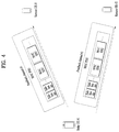
- FIG. 4 is a diagram showing an example of multicast transmission of feedback information by a relay UE.
- a relay UE # 1 can multicast feedback information on several remote UEs (e.g., a remote UE # 1 and a remote UE # 2 ) through a single feedback channel. Namely, the relay UE # 1 can transmit feedback information on the remote UE # 1 and the remote UE # 2 through a single feedback channel (feedback channel # 1 ) on the same physical resource (e.g., time-frequency) by multicast.
- a single feedback channel feedback channel # 1
- Information fed back for the remote UE # 1 and the remote UE # 2 by the relay UE # 1 may include information as follows.
- Feedback information may include a measured block error rate (BLER), a collision rate, a Signal to Interference & Noise Ratio (SINR), a received power, the number of transmissions, and an ACK/NACK signal.
- BLER block error rate
- SINR Signal to Interference & Noise Ratio
- Feedback information may include information for making a request for performing a relay reselection procedure. If SD-RSRP of a specific remote UE is better than a threshold, a relay UE may make a request for performing a relay reselection procedure to the specific remote UE having the SD-RSRP better than the threshold.
- Feedback information may include information indicating that System Information (SI) is transmitted to a remote UE. If a relay UE has system information necessary for a specific remote UE, it can transmit feedback information including the system information to the specific remote UE.
- SI System Information
- FIG. 5 is a diagram showing an example of a feedback operation through a receiving (rx) D-UE.
- an rx D-UE # 1 is assumed as corresponding to a remote UE # 1 .
- a tx D-UE # 1 , a tx D-UE # 2 , and a tx D-UE # 3 are assumed as corresponding to a relay UE # 1 , a relay UE # 2 , and a relay UE # 3 , respectively.
- the rx D-UE # 1 sorts groups by SA resource region and is able to broadcast feedback based on such a group. Each of the tx D-UEs of the corresponding group receives and decodes feedback information, thereby determining whether data of its own data succeeded or failed in transmission through several SA ID (source ID) informations. Moreover, if there are lots of tx D-UEs having failed in data transmission, the rx D-UE # 1 can make a retransmission of a groupcast type by requesting a retransmission in group unit instead of making a request for retransmission to an individual tx D-UE.
- a tx D-UE can perform data transmission by unicast for the specific rx D-UE (e.g., rx D-UE # 1 ).
- the rx D-UE # 1 (e.g., a remote UE # 1 ) can broadcast information such as a measured block error rate (BLER), a collision rate, an SINR, a received power, the number of transmissions, and the like, which are feedback information on the neighboring tx D-UE # 1 , tx D-UE # 2 , and tx D-UE # 3 (e.g., relay UE # 1 , relay UE # 2 , and relay UE # 3 ).
- Such feedback of the rx D-UE # 1 may operate periodically and can be transmitted for specific tx D-UEs (e.g., tx D-UE # 1 ) by event triggering.
- Such events can be defined in various scenarios.
- an event may be triggered: 1) in case that a prescribed number of consecutive TB transmissions failed; 2) in case that a measured Block Error Rate (BLER) is lower than a prescribed threshold (e.g., X %) received from the network; or 3) in case that collision of transmission of report data of SAs of an SA pool occurs (partially), a corresponding event can be triggered. If a prescribed one of the examples of the event occurrence is satisfied, a corresponding event can be triggered.
- BLER Block Error Rate
- an rx D-UE # 1 is assumed as corresponding to a relay UE # 1 .
- a tx D-UE # 1 , a tx D-UE # 2 , and a tx D-UE # 3 are assumed as corresponding to a remote UE # 1 , a remote UE # 2 , and a remote UE # 3 , respectively.
- the rx D-UE # 1 sorts groups by SA resource region and is able to broadcast feedback based on such a group. Each of the tx D-UEs of the corresponding group receives and decodes feedback information, thereby determining whether data of its own data succeeded or failed in transmission through several SA ID (source ID) informations. Moreover, if there are lots of tx D-UEs having failed in data transmission, the rx D-UE # 1 can make a retransmission of a groupcast type by requesting a retransmission in group unit instead of making a request for retransmission to an individual tx D-UE.
- a tx D-UE can perform data transmission by unicast for the specific rx D-UE (e.g., rx D-UE # 1 ).
- the rx D-UE # 1 (e.g., a relay UE # 1 ) can broadcast information such as a measured block error rate (BLER), a collision rate, an SINR, a received power, the number of transmissions, and the like, which are measured as feedback information on the neighboring tx D-UE # 1 , tx D-UE # 2 , and tx D-UE # 3 (e.g., remote UE # 1 , remote UE # 2 , and remote UE # 3 ).
- Such feedback of the rx D-UE # 1 may operate periodically and can be transmitted for specific tx D-UEs (e.g., tx D-UE # 1 ) by event triggering.
- Such events can be defined in various scenarios.
- an event may be triggered: 1) in case that a prescribed number of consecutive TB transmissions failed; 2) in case that a measured Block Error Rate (BLER) is lower than a prescribed threshold (e.g., X %) received from the network; or 3) in case that collision of transmission of report data of SAs of an SA pool occurs (partially), a corresponding event can be triggered. If a prescribed one of the examples of the event occurrence is satisfied, a corresponding event can be triggered.
- BLER Block Error Rate
- the tx D-UEs can reselect resources, adjust MCS, or perform power control operations.
- a method of transmitting feedback information in an FeD2D environment is industrially applicable to various kinds of wireless communication systems such as 3GPP LTE-A system, 5G system, IoT technology, etc.
Landscapes
- Engineering & Computer Science (AREA)
- Computer Networks & Wireless Communication (AREA)
- Signal Processing (AREA)
- Computer Security & Cryptography (AREA)
- Mobile Radio Communication Systems (AREA)
- Data Exchanges In Wide-Area Networks (AREA)
Abstract
Description
-
- Device-to-Device discovery in network coverage (all cases of commercial and public safety uses).
- In Device-to-Device broadcast communication, higher layers support groupcast and unicast communications for in-coverage/part of a network, which mainly targets public safety use cases, and out-of-coverage of the network.
-
- A remote UE and a relay UE are EUTRAN within the coverage.
- A relay UE may be in EUTRAN coverage and a remote UE may be in enhanced coverage (the enhanced coverage means that a UE in CE mode is connected to a network through Rel-13 MTC).
- A relay UE is in the EUTRAN coverage and a remote UE is out of the EUTRAN coverage.
-
- Physical Layer Aspects
-
-
Upper Layer 2 Aspects
-
-
- Physical Layer Aspects
-
-
Upper Layer 2 Aspects
-
Claims (16)
Priority Applications (1)
| Application Number | Priority Date | Filing Date | Title |
|---|---|---|---|
| US16/093,438 US11096086B2 (en) | 2016-04-14 | 2017-04-13 | Method for transmitting feedback information in FED2D environment and apparatus therefor |
Applications Claiming Priority (3)
| Application Number | Priority Date | Filing Date | Title |
|---|---|---|---|
| US201662322754P | 2016-04-14 | 2016-04-14 | |
| PCT/KR2017/004002 WO2017179922A2 (en) | 2016-04-14 | 2017-04-13 | Method for transmitting feedback information in fed2d environment and apparatus therefor |
| US16/093,438 US11096086B2 (en) | 2016-04-14 | 2017-04-13 | Method for transmitting feedback information in FED2D environment and apparatus therefor |
Publications (2)
| Publication Number | Publication Date |
|---|---|
| US20190141566A1 US20190141566A1 (en) | 2019-05-09 |
| US11096086B2 true US11096086B2 (en) | 2021-08-17 |
Family
ID=60042674
Family Applications (1)
| Application Number | Title | Priority Date | Filing Date |
|---|---|---|---|
| US16/093,438 Expired - Fee Related US11096086B2 (en) | 2016-04-14 | 2017-04-13 | Method for transmitting feedback information in FED2D environment and apparatus therefor |
Country Status (2)
| Country | Link |
|---|---|
| US (1) | US11096086B2 (en) |
| WO (1) | WO2017179922A2 (en) |
Cited By (2)
| Publication number | Priority date | Publication date | Assignee | Title |
|---|---|---|---|---|
| US11477831B2 (en) * | 2019-08-19 | 2022-10-18 | Lg Electronics Inc. | Method for relaying unstructured traffic, and relay UE |
| US11627571B2 (en) * | 2018-06-05 | 2023-04-11 | Qualcomm Incorporated | Feedback window to provide early feedback for transmissions in a set of consecutive transmission time intervals |
Families Citing this family (8)
| Publication number | Priority date | Publication date | Assignee | Title |
|---|---|---|---|---|
| EP3223575B1 (en) * | 2015-11-19 | 2019-06-12 | ASUSTek Computer Inc. | Methods and apparatus for switching communication interface in a wireless communication system |
| WO2017183865A2 (en) * | 2016-04-17 | 2017-10-26 | 엘지전자 주식회사 | Method for transmitting signals by considering interferences in fed2d environment and apparatus therefor |
| WO2018062669A1 (en) * | 2016-09-29 | 2018-04-05 | 에스케이텔레콤 주식회사 | Network device and operation method for network device |
| US11229054B2 (en) | 2017-11-06 | 2022-01-18 | Lg Electronics Inc. | Method for feedback for device-to-device communication in wireless communication system, and device for same |
| US11646822B2 (en) | 2018-12-11 | 2023-05-09 | Apple Inc. | Groupcast transmission with feedback for intra-platooning and inter-platooning communications |
| CN109889450B (en) * | 2019-03-13 | 2021-12-21 | 西南交通大学 | Multicast rate control method and multicast transmission equipment |
| CN120835411A (en) * | 2019-04-30 | 2025-10-24 | 中兴通讯股份有限公司 | Wireless communication resource configuration method, wireless communication device and storage medium |
| US20240251326A1 (en) * | 2021-01-15 | 2024-07-25 | Lg Electronics Inc. | Operation method by ue associated with measurement and relay reselection on basis of sd-rsrp and sl-rsrp in sidelink in wireless communication system, and device |
Citations (23)
| Publication number | Priority date | Publication date | Assignee | Title |
|---|---|---|---|---|
| US20140328329A1 (en) * | 2013-05-01 | 2014-11-06 | Samsung Electronics Co., Ltd. | Methods and apparatus for device-to-device communications system |
| US20150023267A1 (en) * | 2012-01-30 | 2015-01-22 | Lg Electronics Inc. | Method for transmitting and receiving feedback information on d2d transmission data in wireless communication system for supporting d2d communication and apparatus therefor |
| US20160095133A1 (en) * | 2014-09-25 | 2016-03-31 | Samsung Electronics Co., Ltd. | Method and apparatus for device-to-device harq process management |
| US20160262111A1 (en) * | 2014-02-10 | 2016-09-08 | Telefonaktiebolaget Lm Ericsson (Publ) | Inter-Network Assisted Power Control for Interference Mitigation of D2D Communications |
| US20160278115A1 (en) * | 2014-10-10 | 2016-09-22 | Telefonaktiebolaget L M Ericsson (Publ) | Wireless Device Reporting |
| US20160309306A1 (en) * | 2013-09-27 | 2016-10-20 | Kyocera Corporation | Communication control method and user terminal |
| US20160381720A1 (en) * | 2015-06-29 | 2016-12-29 | Samsung Electronics Co., Ltd. | Method and apparatus for generating packet data network connection of user equipment |
| US20170013653A1 (en) * | 2015-07-08 | 2017-01-12 | Blackberry Limited | Systems and methods for managing a ue-to-network relay |
| US20170018187A1 (en) * | 2015-07-14 | 2017-01-19 | Samsung Electronics Co., Ltd | Apparatus and method for providing service in vehicle to everything communication system |
| US20170093541A1 (en) * | 2015-09-25 | 2017-03-30 | Asustek Computer Inc. | Method and apparatus for reducing signaling overhead in a wireless communication system |
| US20170202042A1 (en) * | 2014-07-16 | 2017-07-13 | Zte Corporation | Optimizing processing method and apparatus for d2d service |
| US20170208638A1 (en) * | 2016-01-20 | 2017-07-20 | Qualcomm Incorporated | Rate control of device-to-device based relay communication |
| US20170290001A1 (en) * | 2016-03-31 | 2017-10-05 | Telefonaktiebolaget Lm Ericsson (Publ) | Uplink Transmission Timing Control |
| US20170347338A1 (en) * | 2014-12-22 | 2017-11-30 | Zte Corporation | Method for Realizing Device-to-Device Communication Relay Selection, Network Control Node and User Equipment |
| US20170367027A1 (en) * | 2014-12-12 | 2017-12-21 | Sony Corporation | Apparatus and method for wireless communication |
| US20180084369A1 (en) * | 2015-06-08 | 2018-03-22 | Sony Corporation | Wireless communication device and wireless communication method |
| US20180092017A1 (en) * | 2015-04-08 | 2018-03-29 | Interdigital Patent Holdings, Inc. | Realizing Mobile Relays For Device-to-Device (D2D) Communications |
| US20180115362A1 (en) * | 2015-03-31 | 2018-04-26 | Ntt Docomo, Inc. | User apparatus and base station |
| US20180115911A1 (en) * | 2014-03-20 | 2018-04-26 | Zte Corporation | Method, device and system for detecting network coverage condition |
| US20180139694A1 (en) * | 2015-04-09 | 2018-05-17 | Telefonaktiebolaget Lm Ericsson (Publ) | Trigger Conditions for Measurement Reports for Relay Selection |
| US20180352525A1 (en) * | 2016-01-20 | 2018-12-06 | Huawei Technologies Co., Ltd. | Synchronization Information Sending Method and Apparatus |
| US20190199483A1 (en) * | 2016-04-01 | 2019-06-27 | Shanghai Langbo Communication Technology Company Limited | Method and device for narrowband cellular communication |
| US20190289520A1 (en) * | 2015-11-05 | 2019-09-19 | Sony Corporation | Electronic device and wireless communication method in wireless communication system |
-
2017
- 2017-04-13 US US16/093,438 patent/US11096086B2/en not_active Expired - Fee Related
- 2017-04-13 WO PCT/KR2017/004002 patent/WO2017179922A2/en not_active Ceased
Patent Citations (23)
| Publication number | Priority date | Publication date | Assignee | Title |
|---|---|---|---|---|
| US20150023267A1 (en) * | 2012-01-30 | 2015-01-22 | Lg Electronics Inc. | Method for transmitting and receiving feedback information on d2d transmission data in wireless communication system for supporting d2d communication and apparatus therefor |
| US20140328329A1 (en) * | 2013-05-01 | 2014-11-06 | Samsung Electronics Co., Ltd. | Methods and apparatus for device-to-device communications system |
| US20160309306A1 (en) * | 2013-09-27 | 2016-10-20 | Kyocera Corporation | Communication control method and user terminal |
| US20160262111A1 (en) * | 2014-02-10 | 2016-09-08 | Telefonaktiebolaget Lm Ericsson (Publ) | Inter-Network Assisted Power Control for Interference Mitigation of D2D Communications |
| US20180115911A1 (en) * | 2014-03-20 | 2018-04-26 | Zte Corporation | Method, device and system for detecting network coverage condition |
| US20170202042A1 (en) * | 2014-07-16 | 2017-07-13 | Zte Corporation | Optimizing processing method and apparatus for d2d service |
| US20160095133A1 (en) * | 2014-09-25 | 2016-03-31 | Samsung Electronics Co., Ltd. | Method and apparatus for device-to-device harq process management |
| US20160278115A1 (en) * | 2014-10-10 | 2016-09-22 | Telefonaktiebolaget L M Ericsson (Publ) | Wireless Device Reporting |
| US20170367027A1 (en) * | 2014-12-12 | 2017-12-21 | Sony Corporation | Apparatus and method for wireless communication |
| US20170347338A1 (en) * | 2014-12-22 | 2017-11-30 | Zte Corporation | Method for Realizing Device-to-Device Communication Relay Selection, Network Control Node and User Equipment |
| US20180115362A1 (en) * | 2015-03-31 | 2018-04-26 | Ntt Docomo, Inc. | User apparatus and base station |
| US20180092017A1 (en) * | 2015-04-08 | 2018-03-29 | Interdigital Patent Holdings, Inc. | Realizing Mobile Relays For Device-to-Device (D2D) Communications |
| US20180139694A1 (en) * | 2015-04-09 | 2018-05-17 | Telefonaktiebolaget Lm Ericsson (Publ) | Trigger Conditions for Measurement Reports for Relay Selection |
| US20180084369A1 (en) * | 2015-06-08 | 2018-03-22 | Sony Corporation | Wireless communication device and wireless communication method |
| US20160381720A1 (en) * | 2015-06-29 | 2016-12-29 | Samsung Electronics Co., Ltd. | Method and apparatus for generating packet data network connection of user equipment |
| US20170013653A1 (en) * | 2015-07-08 | 2017-01-12 | Blackberry Limited | Systems and methods for managing a ue-to-network relay |
| US20170018187A1 (en) * | 2015-07-14 | 2017-01-19 | Samsung Electronics Co., Ltd | Apparatus and method for providing service in vehicle to everything communication system |
| US20170093541A1 (en) * | 2015-09-25 | 2017-03-30 | Asustek Computer Inc. | Method and apparatus for reducing signaling overhead in a wireless communication system |
| US20190289520A1 (en) * | 2015-11-05 | 2019-09-19 | Sony Corporation | Electronic device and wireless communication method in wireless communication system |
| US20170208638A1 (en) * | 2016-01-20 | 2017-07-20 | Qualcomm Incorporated | Rate control of device-to-device based relay communication |
| US20180352525A1 (en) * | 2016-01-20 | 2018-12-06 | Huawei Technologies Co., Ltd. | Synchronization Information Sending Method and Apparatus |
| US20170290001A1 (en) * | 2016-03-31 | 2017-10-05 | Telefonaktiebolaget Lm Ericsson (Publ) | Uplink Transmission Timing Control |
| US20190199483A1 (en) * | 2016-04-01 | 2019-06-27 | Shanghai Langbo Communication Technology Company Limited | Method and device for narrowband cellular communication |
Non-Patent Citations (6)
| Title |
|---|
| Cao et al "Soft forwarding device cooperation strategies for 5G radio access networks", 2014 IEEE 25th Annual International Symposium on Personal, Indoor, and Mobile Radio Communication (PIMRC) (Year: 2014). * |
| Fujitsu, "Consideration on the Enhancement of UE-to-Network Relay," 3GPP TSG-RAN WG2 Meeting #93bis, R2-162240, Dubrovnik, Croatia, Apr. 11-15, 2016, pp. 1-3. |
| Huawei et al., "General technical consideration on PC5 enhancement for UE-To-NW relay" 3GPP TSG-RAN WG2 Meeting #93bis, R2-162641, Dubrovnik, Croatia, Apr. 11-15, 2016, 4 pages. |
| Lei et al, "Operator controlled device-to-device communications in LTE-advanced networks," IEEE Wireless Commun., vol. 19, No. 3, pp. 96-104, Jun. 2012 (Year: 2012). * |
| Qualcomm Incorporated, "Scenarios for FeD2D," 3GPP TSG-RAN WG2 Meeting #93bis, R2-162741, Dubrovnik, Croatia, Apr. 11-15, 2016, 5 pages. |
| Sony, "Scope and phasing of D2D Relay Enhancements," 3GPP TSG RAN WG2 NB-Meeting #93bis, R2-162636, Dubrovnik, Croatia, Apr. 11-15, 2016, 7 pages. |
Cited By (4)
| Publication number | Priority date | Publication date | Assignee | Title |
|---|---|---|---|---|
| US11627571B2 (en) * | 2018-06-05 | 2023-04-11 | Qualcomm Incorporated | Feedback window to provide early feedback for transmissions in a set of consecutive transmission time intervals |
| US11477831B2 (en) * | 2019-08-19 | 2022-10-18 | Lg Electronics Inc. | Method for relaying unstructured traffic, and relay UE |
| US20230047009A1 (en) * | 2019-08-19 | 2023-02-16 | Lg Electronics Inc. | Method for relaying unstructured traffic, and relay ue |
| US11903057B2 (en) * | 2019-08-19 | 2024-02-13 | Lg Electronics Inc. | Method for relaying unstructured traffic, and relay UE |
Also Published As
| Publication number | Publication date |
|---|---|
| US20190141566A1 (en) | 2019-05-09 |
| WO2017179922A3 (en) | 2018-08-02 |
| WO2017179922A2 (en) | 2017-10-19 |
Similar Documents
| Publication | Publication Date | Title |
|---|---|---|
| US11096086B2 (en) | Method for transmitting feedback information in FED2D environment and apparatus therefor | |
| US11758563B2 (en) | Direct communication method between terminals in wireless communication system, and apparatus therefor | |
| US20250008521A1 (en) | Wireless communication method, terminal device and network device | |
| US11019562B2 (en) | Method and device for transmitting and receiving plurality of D2D signals in wireless communication system | |
| CN110115080B (en) | Method and device for transmitting and receiving signals in wireless communication system | |
| US9515800B2 (en) | Method for transmitting and receiving feedback information on D2D transmission data in wireless communication system for supporting D2D communication and apparatus therefor | |
| US9277539B2 (en) | Method for performing inter-cell device-to-device (D2D) communication in wireless communication system and device therefor | |
| US10455479B2 (en) | Method for relaying discovery signal for terminal-to-terminal direct communication in wireless communication system, and apparatus therefor | |
| US9398560B2 (en) | Method for performing paging in wireless communication system supporting direct communication between terminals, and D2D terminal for the method | |
| US10477488B2 (en) | Method for transmitting signals by considering interferences in FED2D environment and apparatus therefor | |
| US20150045078A1 (en) | Method for d2d terminal transmitting and receiving data in wireless communication system supporting device-to-device communication | |
| US9998210B2 (en) | Apparatus for transceiving signals using a TDD (time division duplex) frame structure in a wireless communication system and method thereof | |
| US11122542B2 (en) | Signal transmission method for V2X communication in wireless communication system, and device therefor | |
| US10616786B2 (en) | Signal transmission method for V2X communication in wireless communication system and apparatus therefor | |
| CN110383743B (en) | Method and apparatus for allocating ACK/NACK resources in wireless communication system | |
| US20250374362A1 (en) | Communication system and communication terminal | |
| US20180249524A1 (en) | Method for handling an id collision for a d2d communication system and device therefor | |
| CN107534982A (en) | Method and device for transmitting/receiving D2D signal in consideration of priority in wireless communication system | |
| CN107925986A (en) | It is used for resource allocation methods and its device of the equipment to equipment communication in wireless communication system | |
| US20240187960A1 (en) | Communication system and base station | |
| CN116569617A (en) | Communication terminal and communication system | |
| US11343770B2 (en) | Method and device for receiving signal through T-RPT in wireless communication system | |
| CN110651521A (en) | Method for allocating resources to signals by terminal in wireless communication system and apparatus therefor | |
| US10681528B2 (en) | Method for device-to-device direct communication in wireless communication system, and apparatus therefor | |
| US20230292224A1 (en) | Communication system, communication terminal, and management device |
Legal Events
| Date | Code | Title | Description |
|---|---|---|---|
| FEPP | Fee payment procedure |
Free format text: ENTITY STATUS SET TO UNDISCOUNTED (ORIGINAL EVENT CODE: BIG.); ENTITY STATUS OF PATENT OWNER: LARGE ENTITY |
|
| AS | Assignment |
Owner name: LG ELECTRONICS INC., KOREA, REPUBLIC OF Free format text: ASSIGNMENT OF ASSIGNORS INTEREST;ASSIGNORS:HONG, JONGWOO;SEO, HANBYUL;REEL/FRAME:047166/0436 Effective date: 20180703 |
|
| STPP | Information on status: patent application and granting procedure in general |
Free format text: DOCKETED NEW CASE - READY FOR EXAMINATION |
|
| STPP | Information on status: patent application and granting procedure in general |
Free format text: NON FINAL ACTION MAILED |
|
| STPP | Information on status: patent application and granting procedure in general |
Free format text: RESPONSE TO NON-FINAL OFFICE ACTION ENTERED AND FORWARDED TO EXAMINER |
|
| STPP | Information on status: patent application and granting procedure in general |
Free format text: FINAL REJECTION MAILED |
|
| STPP | Information on status: patent application and granting procedure in general |
Free format text: DOCKETED NEW CASE - READY FOR EXAMINATION |
|
| STPP | Information on status: patent application and granting procedure in general |
Free format text: NON FINAL ACTION MAILED |
|
| STPP | Information on status: patent application and granting procedure in general |
Free format text: DOCKETED NEW CASE - READY FOR EXAMINATION |
|
| STPP | Information on status: patent application and granting procedure in general |
Free format text: NOTICE OF ALLOWANCE MAILED -- APPLICATION RECEIVED IN OFFICE OF PUBLICATIONS |
|
| STPP | Information on status: patent application and granting procedure in general |
Free format text: PUBLICATIONS -- ISSUE FEE PAYMENT RECEIVED |
|
| STPP | Information on status: patent application and granting procedure in general |
Free format text: PUBLICATIONS -- ISSUE FEE PAYMENT VERIFIED |
|
| STPP | Information on status: patent application and granting procedure in general |
Free format text: AWAITING TC RESP, ISSUE FEE PAYMENT VERIFIED |
|
| STPP | Information on status: patent application and granting procedure in general |
Free format text: PUBLICATIONS -- ISSUE FEE PAYMENT VERIFIED |
|
| STCF | Information on status: patent grant |
Free format text: PATENTED CASE |
|
| FEPP | Fee payment procedure |
Free format text: MAINTENANCE FEE REMINDER MAILED (ORIGINAL EVENT CODE: REM.); ENTITY STATUS OF PATENT OWNER: LARGE ENTITY |
|
| LAPS | Lapse for failure to pay maintenance fees |
Free format text: PATENT EXPIRED FOR FAILURE TO PAY MAINTENANCE FEES (ORIGINAL EVENT CODE: EXP.); ENTITY STATUS OF PATENT OWNER: LARGE ENTITY |
|
| STCH | Information on status: patent discontinuation |
Free format text: PATENT EXPIRED DUE TO NONPAYMENT OF MAINTENANCE FEES UNDER 37 CFR 1.362 |
|
| FP | Lapsed due to failure to pay maintenance fee |
Effective date: 20250817 |