US11095870B1 - Calibration of cameras on unmanned aerial vehicles using human joints - Google Patents
Calibration of cameras on unmanned aerial vehicles using human joints Download PDFInfo
- Publication number
- US11095870B1 US11095870B1 US16/856,511 US202016856511A US11095870B1 US 11095870 B1 US11095870 B1 US 11095870B1 US 202016856511 A US202016856511 A US 202016856511A US 11095870 B1 US11095870 B1 US 11095870B1
- Authority
- US
- United States
- Prior art keywords
- group
- camera
- anchor
- human
- images
- Prior art date
- Legal status (The legal status is an assumption and is not a legal conclusion. Google has not performed a legal analysis and makes no representation as to the accuracy of the status listed.)
- Active
Links
Images


Classifications
-
- G—PHYSICS
- G06—COMPUTING OR CALCULATING; COUNTING
- G06T—IMAGE DATA PROCESSING OR GENERATION, IN GENERAL
- G06T7/00—Image analysis
- G06T7/80—Analysis of captured images to determine intrinsic or extrinsic camera parameters, i.e. camera calibration
- G06T7/85—Stereo camera calibration
-
- B—PERFORMING OPERATIONS; TRANSPORTING
- B64—AIRCRAFT; AVIATION; COSMONAUTICS
- B64C—AEROPLANES; HELICOPTERS
- B64C39/00—Aircraft not otherwise provided for
- B64C39/02—Aircraft not otherwise provided for characterised by special use
- B64C39/024—Aircraft not otherwise provided for characterised by special use of the remote controlled vehicle type, i.e. RPV
-
- B—PERFORMING OPERATIONS; TRANSPORTING
- B64—AIRCRAFT; AVIATION; COSMONAUTICS
- B64C—AEROPLANES; HELICOPTERS
- B64C39/00—Aircraft not otherwise provided for
- B64C39/04—Aircraft not otherwise provided for having multiple fuselages or tail booms
-
- B—PERFORMING OPERATIONS; TRANSPORTING
- B64—AIRCRAFT; AVIATION; COSMONAUTICS
- B64U—UNMANNED AERIAL VEHICLES [UAV]; EQUIPMENT THEREFOR
- B64U10/00—Type of UAV
- B64U10/10—Rotorcrafts
- B64U10/13—Flying platforms
-
- G—PHYSICS
- G05—CONTROLLING; REGULATING
- G05D—SYSTEMS FOR CONTROLLING OR REGULATING NON-ELECTRIC VARIABLES
- G05D1/00—Control of position, course, altitude or attitude of land, water, air or space vehicles, e.g. using automatic pilots
- G05D1/10—Simultaneous control of position or course in three dimensions
- G05D1/101—Simultaneous control of position or course in three dimensions specially adapted for aircraft
- G05D1/104—Simultaneous control of position or course in three dimensions specially adapted for aircraft involving a plurality of aircrafts, e.g. formation flying
-
- G—PHYSICS
- G05—CONTROLLING; REGULATING
- G05D—SYSTEMS FOR CONTROLLING OR REGULATING NON-ELECTRIC VARIABLES
- G05D1/00—Control of position, course, altitude or attitude of land, water, air or space vehicles, e.g. using automatic pilots
- G05D1/20—Control system inputs
- G05D1/24—Arrangements for determining position or orientation
-
- G06K9/00335—
-
- G—PHYSICS
- G06—COMPUTING OR CALCULATING; COUNTING
- G06N—COMPUTING ARRANGEMENTS BASED ON SPECIFIC COMPUTATIONAL MODELS
- G06N20/00—Machine learning
-
- G—PHYSICS
- G06—COMPUTING OR CALCULATING; COUNTING
- G06N—COMPUTING ARRANGEMENTS BASED ON SPECIFIC COMPUTATIONAL MODELS
- G06N3/00—Computing arrangements based on biological models
- G06N3/02—Neural networks
- G06N3/04—Architecture, e.g. interconnection topology
- G06N3/0464—Convolutional networks [CNN, ConvNet]
-
- G—PHYSICS
- G06—COMPUTING OR CALCULATING; COUNTING
- G06N—COMPUTING ARRANGEMENTS BASED ON SPECIFIC COMPUTATIONAL MODELS
- G06N3/00—Computing arrangements based on biological models
- G06N3/02—Neural networks
- G06N3/08—Learning methods
-
- G—PHYSICS
- G06—COMPUTING OR CALCULATING; COUNTING
- G06N—COMPUTING ARRANGEMENTS BASED ON SPECIFIC COMPUTATIONAL MODELS
- G06N3/00—Computing arrangements based on biological models
- G06N3/02—Neural networks
- G06N3/08—Learning methods
- G06N3/09—Supervised learning
-
- G—PHYSICS
- G06—COMPUTING OR CALCULATING; COUNTING
- G06T—IMAGE DATA PROCESSING OR GENERATION, IN GENERAL
- G06T7/00—Image analysis
- G06T7/70—Determining position or orientation of objects or cameras
- G06T7/73—Determining position or orientation of objects or cameras using feature-based methods
- G06T7/74—Determining position or orientation of objects or cameras using feature-based methods involving reference images or patches
-
- G—PHYSICS
- G06—COMPUTING OR CALCULATING; COUNTING
- G06T—IMAGE DATA PROCESSING OR GENERATION, IN GENERAL
- G06T7/00—Image analysis
- G06T7/70—Determining position or orientation of objects or cameras
- G06T7/73—Determining position or orientation of objects or cameras using feature-based methods
- G06T7/75—Determining position or orientation of objects or cameras using feature-based methods involving models
-
- G—PHYSICS
- G06—COMPUTING OR CALCULATING; COUNTING
- G06T—IMAGE DATA PROCESSING OR GENERATION, IN GENERAL
- G06T7/00—Image analysis
- G06T7/80—Analysis of captured images to determine intrinsic or extrinsic camera parameters, i.e. camera calibration
-
- G—PHYSICS
- G06—COMPUTING OR CALCULATING; COUNTING
- G06V—IMAGE OR VIDEO RECOGNITION OR UNDERSTANDING
- G06V10/00—Arrangements for image or video recognition or understanding
- G06V10/70—Arrangements for image or video recognition or understanding using pattern recognition or machine learning
- G06V10/764—Arrangements for image or video recognition or understanding using pattern recognition or machine learning using classification, e.g. of video objects
-
- G—PHYSICS
- G06—COMPUTING OR CALCULATING; COUNTING
- G06V—IMAGE OR VIDEO RECOGNITION OR UNDERSTANDING
- G06V10/00—Arrangements for image or video recognition or understanding
- G06V10/70—Arrangements for image or video recognition or understanding using pattern recognition or machine learning
- G06V10/82—Arrangements for image or video recognition or understanding using pattern recognition or machine learning using neural networks
-
- G—PHYSICS
- G06—COMPUTING OR CALCULATING; COUNTING
- G06V—IMAGE OR VIDEO RECOGNITION OR UNDERSTANDING
- G06V20/00—Scenes; Scene-specific elements
- G06V20/10—Terrestrial scenes
- G06V20/17—Terrestrial scenes taken from planes or by drones
-
- G—PHYSICS
- G06—COMPUTING OR CALCULATING; COUNTING
- G06V—IMAGE OR VIDEO RECOGNITION OR UNDERSTANDING
- G06V40/00—Recognition of biometric, human-related or animal-related patterns in image or video data
- G06V40/10—Human or animal bodies, e.g. vehicle occupants or pedestrians; Body parts, e.g. hands
- G06V40/103—Static body considered as a whole, e.g. static pedestrian or occupant recognition
-
- G—PHYSICS
- G06—COMPUTING OR CALCULATING; COUNTING
- G06V—IMAGE OR VIDEO RECOGNITION OR UNDERSTANDING
- G06V40/00—Recognition of biometric, human-related or animal-related patterns in image or video data
- G06V40/20—Movements or behaviour, e.g. gesture recognition
-
- H—ELECTRICITY
- H04—ELECTRIC COMMUNICATION TECHNIQUE
- H04N—PICTORIAL COMMUNICATION, e.g. TELEVISION
- H04N13/00—Stereoscopic video systems; Multi-view video systems; Details thereof
- H04N13/20—Image signal generators
- H04N13/204—Image signal generators using stereoscopic image cameras
- H04N13/246—Calibration of cameras
-
- H—ELECTRICITY
- H04—ELECTRIC COMMUNICATION TECHNIQUE
- H04N—PICTORIAL COMMUNICATION, e.g. TELEVISION
- H04N13/00—Stereoscopic video systems; Multi-view video systems; Details thereof
- H04N13/20—Image signal generators
- H04N13/282—Image signal generators for generating image signals corresponding to three or more geometrical viewpoints, e.g. multi-view systems
-
- B64C2201/127—
-
- B—PERFORMING OPERATIONS; TRANSPORTING
- B64—AIRCRAFT; AVIATION; COSMONAUTICS
- B64U—UNMANNED AERIAL VEHICLES [UAV]; EQUIPMENT THEREFOR
- B64U2101/00—UAVs specially adapted for particular uses or applications
- B64U2101/30—UAVs specially adapted for particular uses or applications for imaging, photography or videography
-
- G—PHYSICS
- G06—COMPUTING OR CALCULATING; COUNTING
- G06N—COMPUTING ARRANGEMENTS BASED ON SPECIFIC COMPUTATIONAL MODELS
- G06N3/00—Computing arrangements based on biological models
- G06N3/02—Neural networks
- G06N3/04—Architecture, e.g. interconnection topology
- G06N3/044—Recurrent networks, e.g. Hopfield networks
-
- G—PHYSICS
- G06—COMPUTING OR CALCULATING; COUNTING
- G06N—COMPUTING ARRANGEMENTS BASED ON SPECIFIC COMPUTATIONAL MODELS
- G06N3/00—Computing arrangements based on biological models
- G06N3/02—Neural networks
- G06N3/04—Architecture, e.g. interconnection topology
- G06N3/045—Combinations of networks
-
- G—PHYSICS
- G06—COMPUTING OR CALCULATING; COUNTING
- G06T—IMAGE DATA PROCESSING OR GENERATION, IN GENERAL
- G06T2207/00—Indexing scheme for image analysis or image enhancement
- G06T2207/10—Image acquisition modality
- G06T2207/10032—Satellite or aerial image; Remote sensing
-
- G—PHYSICS
- G06—COMPUTING OR CALCULATING; COUNTING
- G06T—IMAGE DATA PROCESSING OR GENERATION, IN GENERAL
- G06T2207/00—Indexing scheme for image analysis or image enhancement
- G06T2207/20—Special algorithmic details
- G06T2207/20081—Training; Learning
-
- G—PHYSICS
- G06—COMPUTING OR CALCULATING; COUNTING
- G06T—IMAGE DATA PROCESSING OR GENERATION, IN GENERAL
- G06T2207/00—Indexing scheme for image analysis or image enhancement
- G06T2207/20—Special algorithmic details
- G06T2207/20084—Artificial neural networks [ANN]
-
- G—PHYSICS
- G06—COMPUTING OR CALCULATING; COUNTING
- G06T—IMAGE DATA PROCESSING OR GENERATION, IN GENERAL
- G06T2207/00—Indexing scheme for image analysis or image enhancement
- G06T2207/30—Subject of image; Context of image processing
- G06T2207/30196—Human being; Person
Definitions
- Various embodiments of the disclosure relate to camera calibration. More specifically, various embodiments of the disclosure relate to a system and method for calibration of cameras mounted on or integrated with unmanned aerial vehicles (UAVs) using human joints.
- UAVs unmanned aerial vehicles
- a system and method for calibration of cameras mounted on or integrated with unmanned aerial vehicles (UAVs) using human joints is provided substantially as shown in, and/or described in connection with, at least one of the figures, as set forth more completely in the claims.
- UAVs unmanned aerial vehicles
- FIG. 1 is a block diagram that illustrates an exemplary network environment for calibration of a group of cameras mounted on or integrated with a group of UAVs by use of human joints, in accordance with an embodiment of the disclosure.
- FIG. 2 is a block diagram that illustrates an exemplary system for calibration of a group of cameras mounted on or integrated with a group of UAVs, in accordance with an embodiment of the disclosure.
- FIG. 3 is a block diagram that illustrates an exemplary UAV, in accordance with an embodiment of the disclosure.
- FIG. 4 is a diagram that illustrates an exemplary implementation of cameras mounted on or integrated with UAVs and anchor cameras devices for acquisition of images of a human subject, in accordance with an embodiment of the disclosure.
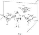
- FIG. 5 is a diagram that illustrates an exemplary implementation of cameras mounted on or integrated with UAVs and anchor cameras devices for acquisition of images of a human subject, in accordance with an embodiment of the disclosure.
- FIG. 6 is a diagram that illustrates exemplary operations for calibration of cameras on UAVs based on human joints, in accordance with an embodiment of the disclosure.
- FIG. 7 is a flowchart that illustrates exemplary operations for calibration of a group of cameras mounted on or integrated with a group of UAVs, in accordance with an embodiment of the disclosure.
- exemplary aspects of the disclosure provide a set of anchor cameras which may be pre-calibrated and fixed at certain known positions and orientations in a 3D space. Further, a group of cameras may be mounted on or integrated with each UAV of a group of UAVs. The group of cameras may not be pre-calibrated for extrinsic camera parameters, such as, translation and rotation parameters.
- the set of anchor cameras and the group of UAVs may surround a human subject in a 3D space.
- a first set of two-dimensional (2D) positions of human joints may be determined from a set of anchor images of the human subject captured by the set of anchor cameras. Further, a second set of 2D positions of the human joints of the human subject may be determined from a group of images of the human subject captured by the group of cameras from multiple three-dimensional (3D) viewpoints.
- the system may compute 3D key-points as 3D positions of the human joints based on a triangulation of the determined first set of 2D positions and may calibrate each of the group of cameras (i.e. extrinsic and/or intrinsic parameters) with respect to the set of anchor cameras or a gauge) by minimizing a 2D re-projection error between the 3D key-points and the second set of 2D positions.
- Use of human joints for camera calibration may be less prone to the point-matching problem, which typically occurs with conventional calibration methods that uses 2D patterns, such as a checkerboard. Also, the use of the human joints for calibration may remove a need for manually placing a calibration pattern, such as a checkerboard in front of an uncalibrated camera.
- FIG. 1 is a block diagram that illustrates an exemplary network environment for calibration of a group of cameras mounted on or integrated with a group of UAVs by use of human joints, in accordance with an embodiment of the disclosure.
- the network environment 100 may include a system 102 and a machine learning (ML) model 104 , which may be included in the system 102 .
- the network environment 100 may further include a set of anchor camera devices 106 , a group of UAVs 108 , and a communication network 110 .
- the set of anchor camera devices 106 may include a first anchor camera device 106 a and a second anchor camera device 106 b .
- the group of UAVs 108 may include a first UAV 108 a and a second UAV 108 b , both of which may be fitted with a camera, such as a first camera 112 a for the first UAV 108 a and a second camera 112 b for the second UAV 108 b .
- the first camera 112 a and the second camera 112 b may be collectively referred as a group of cameras 112 .
- the system 102 may be communicatively coupled to the set of anchor camera devices 106 and the group of UAVs 108 , via the communication network 110 .
- a three-dimensional (3D) space 114 as part of a 3D environment, in which the set of anchor camera devices 106 and the group of UAVs 108 may be deployed.
- a human subject 116 surrounded by the set of anchor camera devices 106 and the group of UAVs 108 .
- the set of anchor camera devices 106 and the group of UAVs 108 may be (e.g., sparsely) located at multiple viewpoints in the 3D space 114 and may collectively form a multi-scanner network having a combined Field-of-View (FoV) that may cover at least an anterior or a posterior side of the body of the human subject 116 .
- the human subject 116 may be a part of the foreground of a scene, which may also include other objects, details and illustrations of which are omitted from the disclosure for the sake of brevity.
- the system 102 may include suitable logic, circuitry, interfaces, and/or code that may be configured to calibrate each camera mounted on or integrated with a respective UAV of the group of UAVs 108 by use of information associated with human joints of the human subject 116 .
- Examples of implementation of the system 102 may include, but are not limited to, a video broadcasting system, an augmented reality-based device, a gaming device, a video processing device, a video editing system, a media production system, a computer workstation, a mainframe computer, a handheld computer, a mobile phone, a smart appliance, a video player, a digital camera, a video camera, a server, a consumer electronic (CE) device, and/or any other computing device with image processing capability.
- the ML model 104 may correspond to a human joint detection framework, such as, a neural network that may be trained on a 2D human joint detection task.
- the ML model 104 may include a trained neural network, which may receive an image of the human subject 116 to detect human joints from the image with a certain confidence score for each of the human joints.
- the ML model 104 may include electronic data, which may be implemented, for example, as a software component, and may rely on code databases, libraries, external scripts, or other logic or instructions for execution of an ML algorithm by a computing system, such as by the system 102 .
- the ML model 104 may be implemented as code and routines configured to enable a computing system, such as the system 102 , to perform human joint detection from an image of the human subject 116 . Additionally, or alternatively, the ML model 104 may be implemented using hardware including a processor, a microprocessor (e.g., to perform or control performance of the one or more operations), a field-programmable gate array (FPGA), or an application-specific integrated circuit (ASIC). In some other instances, the ML model 104 may be implemented using a combination of both hardware and software.
- the ML model 104 may be a neural network model.
- the neural network model may include, but are not limited to, a deep neural network (DNN), a convolutional neural network (CNN), a recurrent neural network (RNN), a CNN-recurrent neural network (CNN-RNN), R-CNN, Fast R-CNN, Faster R-CNN, an artificial neural network (ANN), (You Only Look Once) YOLO network, a Long Short Term Memory (LSTM) network based RNN, CNN+ANN, LSTM+ANN, a gated recurrent unit (GRU)-based RNN, a fully connected neural network, a Connectionist Temporal Classification (CTC) based RNN, a deep Bayesian neural network, a Generative Adversarial Network (GAN), and/or a combination of such networks.
- the neural network model may be based on a hybrid architecture of multiple Deep Neural Networks (DNNs).
- Each of the set of anchor camera devices 106 may include suitable logic, circuitry, interfaces, and/or code that may be configured to capture an image or a plurality of images that may include the human subject 116 .
- Each anchor camera device may be fixed at a certain position in the 3D space 114 .
- an anchor camera device may be fixed at a pre-determined position on a wall or a roof.
- Examples of implementation of an anchor camera device may include, but are not limited to, a pre-calibrated fixed camera in the 3D space 114 , a pre-calibrated camera mounted on or integrated with a UAV that may be configured to maintain a fixed pose in the 3D space 114 , or a pre-calibrated camera that may be moveably coupled to a remotely-controlled camera movement assembly.
- Each UAV of the group of UAVs 108 may include a UAV which may be fitted with a camera (initially uncalibrated). Further, each UAV may be either controlled by a remote system or may be capable of autonomous flights based on preprogrammed routes or paths. In at least one embodiment, each UAV may implement a human tracking method to align itself in the 3D space 114 and to follow the human subject 116 such that the human subject 116 is always in a FOV region of the camera fitted on the respective UAV. In at least one embodiment, each UAV may be controlled by a human pilot from a central control station, which may be a part of as the system 102 .
- each of the group of UAVs 108 may receive control instructions from the system 102 , via the communication network 110 .
- the control instructions may include a 3D position (X-axis, Y-axis, or Z-axis) or a 3D path based on which one or more of the group of UAVs 108 may move in the 3D space 114 .
- such instructions may include tilt or orientation information which may be associated with a 3D pose of each UAV in the 3D space 114 .
- the group of UAVs 108 may control their tilt angle or orientation as well as vertical alignment or horizontal alignment based on the control instructions received from the system 102 .
- Examples of a UAV may include, but are not limited to, a camera drone, a camera-fitted smart plane, or other airborne vehicles which may be controlled based on pre-programmed flight plans and/or automation systems (such as by the system 102 ).
- examples of a UAV may include, but are not limited to, a tri-copter with three arms and one motor, a quad-copter with four arms and one motor, a hexa-copter with six arms and one motor, a Y6-copter with six arms and six motors, an octo-copter with eight arms and one motor, and/or an X8-copter with eight arms and eight motors.
- Each of the first camera 112 a and the second camera 112 b may include suitable logic, circuitry, interfaces, and/or code that may be configured to capture an image or a plurality of images that may include the human subject 116 .
- Each of the first camera 112 a and the second camera 112 b may be mounted on or integrated with a UAV.
- Examples of the first camera 112 a and the second camera 112 b may include, but are not limited to, a single-lens reflex camera, a digital single-lens reflex camera, a studio or broadcast grade camera, a high-speed camera, a wide-angle camera, an action camera, a closed-circuit television (CCTV) camera, a camcorder, a digital camera, camera phones, a time-of-flight camera (ToF camera), a night-vision camera, and/or other image capture devices.
- CCTV closed-circuit television
- ToF camera time-of-flight camera
- night-vision camera and/or other image capture devices.
- the communication network 110 may include a communication medium through which the system 102 , the set of anchor camera devices 106 , and the group of UAVs 108 may communicate with each other.
- Examples of the communication network 110 may include, but are not limited to, internet, a cloud network, a Wireless Fidelity (Wi-Fi) network, a Personal Area Network (PAN), a Local Area Network (LAN), or a Metropolitan Area Network (MAN).
- Various devices in the network environment 100 may be configured to connect to the communication network 110 , in accordance with various wired and wireless communication protocols.
- wired and wireless communication protocols may include, but are not limited to, a Transmission Control Protocol and Internet Protocol (TCP/IP), User Datagram Protocol (UDP), Hypertext Transfer Protocol (HTTP), File Transfer Protocol (FTP), Zig Bee, EDGE, IEEE 802.11, light fidelity (Li-Fi), 802.16, IEEE 802.11s, IEEE 802.11g, multi-hop communication, wireless access point (AP), device to device communication, cellular communication protocols, and Bluetooth (BT) communication protocols.
- TCP/IP Transmission Control Protocol and Internet Protocol
- UDP User Datagram Protocol
- HTTP Hypertext Transfer Protocol
- FTP File Transfer Protocol
- Zig Bee EDGE
- AP wireless access point
- BT Bluetooth
- the 3D space 114 may be a built environment (e.g., an indoor, an outdoor, or a studio space) or a natural environment in which images of the human subject 116 may be captured from multiple viewpoints.
- a built environment e.g., an indoor, an outdoor, or a studio space
- a natural environment in which images of the human subject 116 may be captured from multiple viewpoints.
- the system 102 may receive a user input from a user (such as the human subject 116 or another human operator) through a user interface of the system 102 .
- the user input may instruct the system 102 to calibrate each camera (such as the first camera 112 a and the second camera 112 b ) mounted on or integrated with the group of UAVs 108 .
- images may be acquired from the set of anchor camera device 106 and from the cameras (the first camera 112 a and the second camera 112 b ) mounted on or integrated with the group of UAVs 108 . Thereafter, the system 102 may receive a set of anchor images of the human subject 116 from the set of anchor camera devices 106 . Additionally, the system 102 may receive a group of images of the human subject 116 from the cameras mounted on or integrated with the group of UAVs 108 . The received group of images may be acquired from multiple viewpoints in the 3D space 114 . For example, a first number of images from the group of images may be captured by the first camera 112 a , while remaining number of images may be captured by the second camera 112 b.
- the system 102 may determine a first set of 2D positions of the human joints for the human subject 116 in each anchor image of the received set of anchor images.
- the set of anchor images captured by the set of anchor camera devices 106 may include accurate positions of key-points of objects (e.g., 2D positions of the human joints) as each of the anchor camera devices may be pre-calibrated and fixed to a known location in the 3D space 114 .
- the positions of the human joints may be treated as rigid and articulate points in the 3D space 114 .
- distance between the human joints may be set based on experimental results.
- the system 102 may further determine a second set of 2D positions of the human joints for the human subject 116 in each image of the received group of images.
- the system 102 may use the ML model 104 to determine the first set of 2D positions from the set of anchor images and to determine the second set of 2D positions from the group of images.
- Examples of the implementation of the ML model 104 may include, but are not limited to, Open Pose, Alpha Pose, and Mask Region-Convolution Neural Network (R-CNN).
- the system 102 may further compute 3D positions of the human joints in the 3D space 114 as 3D key-points, based on a triangulation (e.g., using a geometric triangulation method) using the determined first set of 2D positions of the human joints. Further, the system 102 may determine a 2D reprojection error between the 3D key-points and the determined second set of 2D positions. The system 102 may calibrate each camera on a respective UAV of the group of UAVs 108 by minimizing the determined 2D reprojection error. For example, for calibration of the first camera 112 a , the 3D key-points may be re-projected onto an image plane of the first camera 112 a mounted on or integrated with the first UAV 108 a .
- a triangulation e.g., using a geometric triangulation method
- a reprojection error may be determined between each re-projected 3D key-point and a 2D position of a corresponding human joint.
- An objective function may be formulated and solved to minimize the re-projection error.
- the aforementioned method may be repeated for the second camera 112 b as well.
- 3D key-point based camera calibration of the cameras may result in estimation of values of extrinsic calibration parameters (i.e. a 3D pose) for each camera fitted on a respective UAV of the group of UAVs 108 .
- the detection of the 2D positions of the human joints of the human subject 116 based on the ML model 104 may be less error prone and may not require manual inputs.
- the system 102 may compute larger number of 3D key-points as compared to a number of key-points that may be computed based on traditional camera calibration techniques which use conventional 2D patterns, such as checker-board patterns.
- the disclosed camera calibration technique may be less prone to the point-mismatch problem as the point mis-matching errors, if any, may be suppressed by use of one or more statistical techniques on the large number of the 3D key-points.
- use of human joints for calibration may remove a need for manually placing a calibration pattern, such as checkerboards.
- FIG. 2 is a block diagram that illustrates an exemplary system for calibration of a group of cameras mounted on or integrated with a group of UAVs, in accordance with an embodiment of the disclosure.
- FIG. 2 is explained in conjunction with elements from FIG. 1 .
- the system 102 may include circuitry 202 , a memory 204 , an input/output (I/O) device 206 , and a network interface 208 .
- the circuitry 202 may be communicatively coupled to the memory 204 , the I/O device 206 , and the network interface 208 .
- the circuitry 202 may be communicatively coupled through the communication network 110 to the set of anchor camera devices 106 and the group of cameras 112 mounted on or integrated with the group of UAVs 108 .
- the group of UAVs 108 may include the first UAV 108 a which may carry the first camera 112 a and the second UAV 108 b which may carry the second camera 112 b .
- the set of anchor camera devices 106 is shown to include the first anchor camera device 106 a and the second anchor camera device 106 b.
- the circuitry 202 may include suitable logic, circuitry, interfaces, and/or code that may be configured to execute instructions stored in the memory 204 .
- the executed instructions may correspond to a set of control operations for calibration of each camera of the group of cameras 112 (such as the first camera 112 a and the second camera 112 b ) mounted on or integrated with the group of UAVs 108 .
- the circuitry 202 may be implemented based on processor technologies known in the art.
- Examples of the circuitry 202 may include, but are not limited to, a Graphical Processing Unit (GPU), a co-processor, a Central Processing Unit (CPU), x86-based processor, a Reduced Instruction Set Computing (RISC) processor, an Application-Specific Integrated Circuit (ASIC) processor, a Complex Instruction Set Computing (CISC) processor, and a combination thereof.
- GPU Graphical Processing Unit
- CPU Central Processing Unit
- RISC Reduced Instruction Set Computing
- ASIC Application-Specific Integrated Circuit
- CISC Complex Instruction Set Computing
- the memory 204 may include suitable logic, circuitry, interfaces, and/or code that may be configured to store the instructions executable by the circuitry 202 . Also, the memory 204 may be configured to store the set of anchor images and the group of images of the human subject 116 . The memory 204 may be further configured to store the ML model 104 that may be used for determination of the first set of 2D positions of the human joints from the set of anchor images and the second set of 2D positions of the human joints from the group of images. Also, the memory 204 may store the X, Y, and Z co-ordinates of the computed 3D key-points.
- Examples of implementation of the memory 204 may include, but are not limited to, Random Access Memory (RAM), Read Only Memory (ROM), Electrically Erasable Programmable Read-Only Memory (EEPROM), Hard Disk Drive (HDD), a Solid-State Drive (SSD), a CPU cache, and/or a Secure Digital (SD) card.
- RAM Random Access Memory
- ROM Read Only Memory
- EEPROM Electrically Erasable Programmable Read-Only Memory
- HDD Hard Disk Drive
- SSD Solid-State Drive
- CPU cache volatile and/or a Secure Digital (SD) card.
- SD Secure Digital
- the I/O device 206 may include suitable logic, circuitry, interfaces, and/or code that may be configured to receive an input from a user and provide an output to the user based on the received input.
- the I/O device 206 may include various input and output devices, which may be configured to communicate with the circuitry 202 . Examples of the input devices may include, but are not limited to, a touch screen, a keyboard, and/or a mouse. Examples of the output devices may include, but are not limited to, a display, and an audio device.
- the network interface 208 may include suitable logic, circuitry, interfaces, and/or code that may be configured to establish a communication between the system 102 , the set of anchor camera devices 106 , the group of cameras 112 , and the group of UAVs 108 , via the communication network 110 .
- the network interface 208 may be implemented by use of various known technologies to support wired or wireless communication by the system 102 via the communication network 110 .
- the network interface 208 may include, but is not limited to, an antenna, a radio frequency (RF) transceiver, one or more amplifiers, a tuner, one or more oscillators, a digital signal processor, a coder-decoder (CODEC) chipset, a subscriber identity module (SIM) card, and/or a local buffer.
- RF radio frequency
- CODEC coder-decoder
- SIM subscriber identity module
- the network interface 208 may communicate via wireless communication with networks, such as the Internet, an Intranet and/or a wireless network, such as a cellular telephone network, a wireless local area network (LAN) and/or a metropolitan area network (MAN).
- the wireless communication may use any of a plurality of communication standards, protocols and technologies, such as Global System for Mobile Communications (GSM), Enhanced Data GSM Environment (EDGE), wideband code division multiple access (W-CDMA), Long Term Evolution (LTE), code division multiple access (CDMA), time division multiple access (TDMA), Bluetooth, Wireless Fidelity (Wi-Fi) (such as IEEE 802.11a, IEEE 802.11b, IEEE 802.11g and/or IEEE 802.11n), voice over Internet Protocol (VoIP), light fidelity (Li-Fi), Wi-MAX, a protocol for email, instant messaging, and/or Short Message Service (SMS).
- GSM Global System for Mobile Communications
- EDGE Enhanced Data GSM Environment
- W-CDMA wideband code division multiple access
- the functions or operations executed by the system 102 may be performed by the circuitry 202 . Operations executed by the circuitry 202 are described in detail, for example, in the FIGS. 4, 5, and 6 .
- FIG. 3 is a block diagram of an exemplary UAV, in accordance with an embodiment of the disclosure.
- FIG. 3 is explained in conjunction with elements from FIG. 1 and FIG. 2 .
- a block diagram 300 of the first UAV 108 a which may be one of the group of UAVs 108 .
- the first UAV 108 a may include circuitry 302 , a memory 304 , a I/O device 306 , a position sensor 308 , a propulsion system 310 , and a network interface 312 .
- the propulsion system 310 may include motors 314 , propellers 316 , an electronic speed controller (ESC) 318 , and a battery 320 .
- ESC electronic speed controller
- first UAV 108 a may also include other suitable components or systems, in addition to the components or systems which are illustrated herein to describe and explain the function and operation of the present disclosure. A detailed description for other components or systems of the first UAV 108 a is omitted from the disclosure for the sake of brevity.
- the first UAV 108 a and the system 102 may be communicatively coupled to each other, via the communication network 110 .
- the first camera 112 a may be configured to be mounted on or integrated with the first UAV 308 a so that the first camera 112 a can have various degrees of freedom (DOF), such as 6 DOF in the 3D space 114 .
- DOF degrees of freedom
- the functions of the circuitry 302 , the memory 304 , the I/O device 306 , and the network interface 312 as shown in the block diagram 300 of the first UAV 108 a , may be same as the functions of the circuitry 202 , the memory 204 , the I/O device 206 , and the network interface 208 , as described, for example, in FIG. 2 . Therefore, the description of the circuitry 302 , the memory 304 , the I/O device 306 , and the network interface 312 is omitted from the disclosure for the sake of brevity.
- the position sensor 308 may include suitable logic, circuitry, interfaces, and/or code that may be configured to determine a current position of the first UAV 108 a in the 3D space 114 . In at least one embodiment, the position sensor 308 may also determine an orientation (along a pitch axis, a roll axis, or yaw axis) in the 3D space 114 . The position sensor 308 may communicate the current position and/or the orientation of the first UAV 108 a to the circuitry 302 and/or the system 102 .
- the circuitry 302 and/or the system 102 may control a position and/or an orientation of the first UAV 108 a based on the communicated current position and/or the orientation of the first UAV 108 a .
- the position sensor 308 may include, but are not limited to, a Global Navigation Satellite System (GNSS) receiver, a motion sensor, a tilt sensor, an accelerometer, a gyro sensor, an Inertial Measurement Unit (IMU), or a sensing camera.
- GNSS Global Navigation Satellite System
- IMU Inertial Measurement Unit
- the position sensor 308 may be implemented as an infra-red (IR) marker sensor or a pattern code scanner.
- IR marker sensor a source of IR light may be affixed at a pre-determined position in the 3D space 114 .
- the source may emit IR light in periodic flashes or in a continuous manner and the first camera 112 a mounted on or integrated with the first UAV 108 a may track and capture the emitted IR light as one or more IR-images.
- the circuitry 302 may apply a 3D pose estimation technique (such as, Pose from Orthography and Scaling with Iteration (POSIT) method) on the one or more IR-images to determine a position and/or an orientation of the first UAV 108 a with respect to the source of the IR light.
- POSIT Pose from Orthography and Scaling with Iteration
- the pre-determined position of the source of IR light may be known and stored in the memory 304 of the first UAV 108 a .
- the circuitry 302 may determine an absolute position and/or orientation of the first UAV 108 a based on the pre-determined position of the source of the IR light and the determined position and/or orientation of the first UAV 108 a.
- a pattern code marker for example, a QR code marker or a bar code marker
- the first camera 112 a may track the pattern code marker and capture an image of the pattern code marker.
- the memory 304 may store a reference image of the pattern code marker and the pre-determined position of the pattern code marker.
- the circuitry 302 may compare the captured image with the reference image to determine a position and/or an orientation of the first UAV 108 a with respect to the pattern code marker. Also, the circuitry 302 may determine an absolute position and/or orientation of the first UAV 108 a based on the pre-determined position of the pattern code marker and the determined position and/or orientation of the first UAV 108 a.
- the propulsion system 310 may include a set of mechanical, electrical, or fuel-based components which may generate a lifting force and a thrust to move the first UAV 108 a between two positions in the 3D space 114 .
- the propulsion system 310 may control the movement of the first UAV 108 a based on one or more control instructions received from the circuitry 302 or the system 102 .
- the propulsion system 310 may further include the motors 314 , the propellers 316 , the ESC 318 , and the battery 320 .
- Circuitry (such as the circuitry 302 ), a memory (such as the memory 304 ), a I/O device (such as the I/O device 306 ), a position sensor (such as the position sensor 308 ), a propulsion system (such as the propulsion system 310 ), and a network interface (such as the network interface 312 ) may also be included in other UAVs of the group of UAVs 108 .
- the first UAV 108 a may act as a master UAV and other UAVs may act as slave UAVs which may receive one or more control instructions from the master UAV.
- FIG. 4 is a diagram that illustrates an exemplary implementation of cameras mounted on or integrated with UAVs and anchor cameras devices for acquisition of images of a human subject, in accordance with an embodiment of the disclosure.
- FIG. 4 is explained in conjunction with elements from FIG. 1, 2 , or 3 .
- a diagram 400 that depicts an arrangement of a first anchor camera 402 a and a second anchor camera 402 b (collectively referred as a set of anchor cameras 402 ) that may face a posterior side of the human subject 116 .
- the diagram 400 also depicts an arrangement of a first camera 404 a and a second camera 404 b (collectively referred to as a group of cameras 404 ) mounted on or integrated with a first UAV 406 a and a second UAV 406 b , respectively.
- the first UAV 406 a and the second UAV 406 b may be collectively referred as a group of UAVs 406 and that may face an anterior side of the human subject 116 .
- Each of the set of anchor cameras 402 may correspond to a pre-calibrated camera that may be fixed to a position (e.g., a certain surface, such as, a ceiling, floor, or a wall or a stationary structure).
- the first anchor camera 402 a and the second anchor camera 402 b may be configured to capture a first anchor image and a second anchor image, respectively (collectively referred as a set of anchor images) of the human subject 116 .
- the set of anchor cameras 402 may be controlled by the system 102 based on control instructions shared via the communication network 110 .
- the system 102 may control the group of UAVs 406 to move at the multiple viewpoints in the 3D space 114 and may control the group of cameras 404 mounted on or integrated with the group of UAVs 406 to acquire the group of images of the human subject 116 from such viewpoints.
- such viewpoints may be selected by the system 102 to ensure that the FOV region of each of the group of cameras 404 captures a portion of the body of the human subject 116 , from which a minimum required number of the human joints can be later detected.
- the set of anchor cameras 402 and the group of cameras 404 mounted on or integrated with the group of UAVs 406 may transmit the set of anchor images and the group of images of the human subject 116 , respectively, to the system 102 .
- Calibration of the first camera 404 a and the second camera 404 b based on the set of anchor images and the group of images is explained in detail, for example, in FIG. 6 .
- FIG. 5 is a diagram that illustrates an exemplary implementation of cameras mounted on or integrated with UAVs and anchor cameras devices for acquisition of images of a human subject, in accordance with an embodiment of the disclosure.
- FIG. 5 is explained in conjunction with elements from FIGS. 1, 2, and 3 .
- a diagram 500 that depicts a first camera 502 a , a second camera 502 b , and a third camera 502 c in the 3D space 114 .
- the first camera 502 a , the second camera 502 b , and the third camera 502 c may be mounted on or integrated with a first UAV 504 a , a second UAV 504 b and a third UAV 504 c , respectively.
- the first UAV 504 a may maintain a fixed pose in the 3D space 114 .
- the fixed pose may correspond to a static position and static orientation (roll, yaw, pitch) of the first UAV 504 a in the 3D space 114 .
- the assembly of the first camera 502 a and the first UAV 504 a may be designated as an anchor camera device that may use the first camera 502 a to capture a set of anchor images of the human subject 116 while remaining in the fixed pose.
- the first camera 502 a may be pre-calibrated with respect to the fixed pose of the first UAV 504 a .
- the remaining UAVs may be controlled to move relatively to the fixed pose to acquire a group of images of the human subject 116 from multiple viewpoints.
- the system 102 may control each of the second UAV 504 b and the third UAV 504 c to move to such viewpoints and capture the group of images from such viewpoints in the 3D space 114 .
- the first UAV 504 a or the first camera 502 a on the first UAV 504 a may transmit the set of anchor images of the human subject 116 to the system 102 .
- the group of cameras i.e., the second camera 502 b and the third camera 502 c
- Calibration of the second camera 502 b and the third camera 502 c may be based on the set of anchor images and the group of images, as is explained in detail, for example, in FIG. 6 .
- FIG. 6 is a diagram that illustrates exemplary operations for calibration of cameras on UAVs based on human joints, in accordance with an embodiment of the disclosure.
- FIG. 6 is explained in conjunction with elements from FIG. 1, 2, 3, 4 , or 5 .
- the exemplary operations illustrated in the diagram 600 may start at 602 and may be performed by any computing system, apparatus, or device, such as by the system 102 of FIG. 1 or the circuitry 302 of FIG. 3 .
- the operations associated with one or more of the blocks of the diagram 600 may be divided into additional blocks, combined into fewer blocks, or eliminated, depending on the particular implementation.
- data acquisition may be performed.
- the circuitry 202 may control the set of anchor cameras 402 (which includes the first anchor camera 402 a and the second anchor camera 402 b ) to capture a set of anchor images of the human subject 116 .
- the set of anchor cameras 402 may be fixed at certain positions in the 3D space 114 from where the set of anchor cameras 402 may capture the set of anchor images.
- the circuitry 202 may control the group of UAVs 406 to move the group of UAVs 406 at multiple viewpoints in the 3D space 114 . Thereafter, the group of cameras 404 mounted on or integrated with the group of UAVs 406 may be controlled to acquire the group of images of the human subject 116 from the multiple viewpoints.
- the group of cameras 404 mounted on or integrated with the group of UAVs 406 may be controlled to acquire the group of images of the human subject 116 from the multiple viewpoints.
- the circuitry 202 may receive the set of anchor images from the set of anchor cameras 402 and receive the group of images from the group of cameras 404 mounted on or integrated with the group of UAVs 406 , via the communication network 110 .
- a first set of 2D positions of human joints may be determined from the set of anchor images.
- the circuitry 202 may be configured to determine the first set of 2D positions of the human joints of the human subject 116 from the set of anchor images (for example, the anchor image 602 a ). For such determination, the circuitry 202 may apply the ML model 104 on each anchor image (such as the anchor image 602 a ) of the set of anchor images.
- the ML model 104 may correspond to a human-joint detection framework that may include a neural network trained on a human joint detection task.
- 2D positions (i.e., the first set of 2D positions) of the human joints may be represented by equation (1), given as follows: ⁇ ( u i n ,v i n ,w i n ,t i n )
- the anchor image 602 a may be captured from a posterior view of the human subject 116 .
- the human joint positions 612 a and 612 b may correspond to a head and a neck, respectively, of the human subject 116 in the anchor image 602 a .
- the human joint positions 612 c , 612 d , and 612 e may correspond to a left shoulder joint, a left elbow joint, and a left wrist joint of the human subject 116 in the anchor image 602 a .
- the human joint positions 612 f , 612 g , and 612 h may correspond to a right shoulder joint, a right elbow joint, and a right wrist joint of the human subject 116 in the anchor image 602 a .
- the human joint positions 612 i , 612 j , and 612 k may correspond to a left waist joint, a left knee joint, and a left ankle joint of the human subject 116 in the anchor image 602 a
- the human joint positions 612 l , 612 m , and 612 n may correspond to a right waist joint, a right knee joint, and a right ankle joint of the human subject 116 in the anchor image 602 a.
- a second set of 2D positions of the human joints may be detected from the group of images.
- the circuitry 202 may be configured to detect the second set of 2D positions of the human joints of the human subject 116 from the group of images (for example, the image 602 b ). To detect the second set of 2D positions, the circuitry 202 may apply the ML model 104 on each image (e.g., the image 602 b ) from the group of images.
- the second set of 2D positions may be also be given by equation (1).
- the circuitry 202 may determine the second set of 2D positions of the human joints of the human subject 116 from the image 602 b as human joint positions 614 a to 614 n .
- the image 602 b may be captured from an anterior portion of the human subject 116 .
- the human joint positions 614 a and 614 b may correspond to a head and a neck of the human subject 116 in the image 602 b .
- the human joint positions 614 c , 614 d , and 614 e may correspond to a right shoulder joint, a right elbow joint, and a right wrist joint of the human subject 116 in the image 602 b .
- the human joint positions 614 f , 614 g , and 614 h may correspond to a left shoulder joint, a left elbow joint, and a left wrist joint of the human subject 116 in the image 602 b .
- the human joint positions 614 i , 616 j , and 614 k may correspond to a right waist joint, a right knee joint, and a right ankle joint of the human subject 116 in the image 602 b
- the human joint positions 614 l , 614 m , and 614 n may correspond to a left waist joint, a left knee joint, and a left ankle joint of the human subject 116 in the image 602 b.
- 3D key-points 618 may be computed.
- the circuitry 202 may compute 3D positions of the human joints of the human subject 116 based on a triangulation using the determined first set of 2D positions of the human joints.
- the circuitry 202 may designate the 3D key-points 618 as the computed 3D positions of the human joints of the human subject 116 with respect to a 3D co-ordinate system 620 .
- the computation of the 3D key-points 618 is explained herein.
- a simple perspective camera model may be adopted to convert human joint position values from the 2D image-plane to the 3D real-space.
- perspective projection-rays (with weight and label) for each detected human joint point may be obtained by use of the pre-determined intrinsic camera parameters and Special Euclidian Group in 3 dimensions (i.e., se(3) parameters).
- the perspective camera model as per the above scenario may be represented as follows: ⁇ ( u i n ,v i n ,w i n ,t i n )
- the circuitry 202 may perform the triangulation using the first set of 2D positions of the human joints along a 3D line (i.e., a ray) by using a known or calibrated optical center of a calibrated camera (e.g., the first anchor camera 402 a ).
- a calibrated camera e.g., the first anchor camera 402 a
- e as a normalized directional 3D vector associated with a 2D position (from the first set of 2D positions) of a certain human joint along a 3D line through the calibrated optical center.
- e may represent the normalized directional 3D vector of the particular human joint from the calibrated camera along the 3D line.
- a as a 3D point on that 3D line through the calibrated optical center.
- the 3D point “a” on the 3D line may represent a camera position of an intrinsically calibrated camera (e.g., the first anchor camera 402 a ) of a known pose.
- the circuitry 202 may determine a weighted least square of multiple 3D lines and the respective multiple normalized 3D vectors “e n ” for a human joint for different positions of the anchor camera (such as the first anchor camera 402 a ).
- each of these multiple 3D lines passes through a respective 3D point of multiple 3D points “a n ” which represent different positions of the anchor camera.
- the weighted least square is represented in equations (4.1) and (4.2), as follows:
- D 2 ⁇ n ⁇ w n ⁇ d n 2 ( 4.1 )
- D 2 ⁇ n ⁇ w n ⁇ [ ⁇ x - a n ⁇ 2 - ⁇ e n ⁇ ( x - a n ) ⁇ 2 ] ( 4.2 )
- w n may represent a weight of n th 3D line
- d n may represent the distance between the 3D point “an” and the n th 3D line.
- Equation (4.2) may be expanded for x-axis co-ordinates of a 3D point along a 3D line.
- Equation (4.2) is given by equation (5), as follows:
- D 2 ⁇ n ⁇ w n ⁇ [ ⁇ i ⁇ ⁇ x - a i n ⁇ 2 - ⁇ ⁇ i ⁇ e n ⁇ ( x - a i n ) ⁇ 2 ] ( 5 )
- i may represent an index of the x-axis co-ordinate of a 3D point along a 3D line.
- the circuitry 202 may apply a partial derivative operation on the equation (5) to obtain equation (6), as follows:
- j may represent an index of y-axis co-ordinate of a 3D point along a 3D line.
- a ij ⁇ n ⁇ w n ⁇ ( e i n ⁇ e j n - ⁇ ij ) ( 8.1 )
- B i ⁇ n ⁇ w n ⁇ ( ⁇ j ⁇ a j n ⁇ e j n ⁇ e i n - a i n ) ( 8.2 )
- the circuitry 202 may compute a first 3D key-point of the 3D key-points 618 based on the solution ⁇ x i ⁇ of the linear system of equations (8.1) and (8.2).
- the first 3D key-point may be associated with one of the human joints.
- the circuitry 202 may compute remaining 3D key-points associated with remaining human joints using the respective 2D position from determined first set of 2D positions by following the abovementioned method.
- the group of cameras 404 mounted on or integrated with the group of UAVs 406 may be calibrated.
- the circuitry 202 may calibrate the first camera 404 a and the second camera 404 b by estimation of a 3D pose (position and orientation) of each of the first camera 404 a and the second camera 404 b .
- Special Euclidean se(3) Lie algebraic parameterization may be used, as per equation 9: ⁇ ( x 0 n ,x 1 n ,x 2 n ,x 3 n ,x 4 n ,x 5 n ) ⁇ se (3)
- the Special Euclidean Lie algebra se(3) may have 6 elements.
- the first 3 elements (x 0 n , x 1 n , x 2 n ) may denote Special Orthogonal Lie algebra (i.e., so(3)), and the later 3 rotation elements (x 3 n , x 4 n , x 5 n ) may denote translation elements T(3) ⁇ R 3 in 3D space, respectively.
- Special Orthogonal Lie algebra i.e., so(3)
- the later 3 rotation elements x 3 n , x 4 n , x 5 n
- T(3) ⁇ R 3 in 3D space respectively.
- exponential mapping se(3) ⁇ SE(3) may be adopted for getting matrix representation.
- values of intrinsic calibration parameters of each of the multiple cameras may be pre-determined or given.
- the circuitry 202 may use a “trivial gauge fixing” in bundle adjustment based technique to set the global gauge for the calibration of the group of cameras 404 (e.g., the first camera 404 a and the second camera 404 b ), by use of equations (10) and (11).
- the circuitry 202 may be configured to calibrate the group of cameras 404 (e.g., the first camera 404 a and the second camera 404 b ) by estimation of the 3D pose (i.e. extrinsic camera parameters, such as position (i.e., translation parameters) and orientation (i.e., rotation parameters)) for each camera of the group of cameras 404 .
- the 3D pose i.e. extrinsic camera parameters, such as position (i.e., translation parameters) and orientation (i.e., rotation parameters)
- an optimization problem in terms of a 2D reprojection error may be formulated.
- the circuitry 202 may determine a 2D reprojection error between the 3D key-points 618 and the determined second set of 2D positions of the human joints. Thereafter, the calibration may be performed by minimizing the determined 2D reprojection error using the formulated optimization problem.
- the 3D key-points 618 may be re-projected onto an image plane of the first camera 404 a . Thereafter, a reprojection error may be determined between each re-projected 3D key-point and a 2D position of a corresponding human joint. An objective function for an optimization problem may be formulated and solved to minimize the re-projection error. The aforementioned method may be repeated for the second camera 404 b as well. As cameras on each UAV of the group of UAVs 406 may be initially un-calibrated, 3D key-point based camera calibration of the cameras may result in estimation of values of extrinsic calibration parameters (i.e.
- the 2D reprojection error may correspond to a geometric error between a point projected based on a perspective camera model view and a measured position of the point in the 3D co-ordinate system 620 .
- the 2D reprojection error may quantify a closeness of an estimate of a 3D key-point with respect to the point's action projection (e.g., the determined second set of 2D positions of the human joints).
- a 3D key-point (a target point) of a human joint is represented by co-ordinates (X, Y, Z) in the 3D co-ordinate system 620 .
- the 3D key-point may be re-projected as a 2D point on an image plane associated with an optical center of a camera (such as one of the group of cameras 404 ).
- the 2D point may be represented by (x p /z p , y p /z p ).
- x p , y p , z p may respectively be x-axis, y-axis, and z-axis co-ordinates of a perspective projection of the re-projected 3D point on the image plane.
- a 2D position of the human joint on the image plane of the camera may be represented by a 2D point (x d , y d ).
- xp, yp, and zp are given by equation (13), as follows:
- the foregoing technique for the calibration of the group of cameras 404 may be referred to as a frame-by-frame calibration technique. Such process may be parallelized for processing on several electronic devices or several processors of a computing device.
- the present disclosure may also be applicable to other techniques for the calibration of the group of cameras 404 , such as a temporal accumulation-based camera calibration technique.
- At least one UAV (e.g., the first UAV 406 a ) of the group of UAVs 406 may include a position sensor.
- the position sensor may be one of a Global Navigation Satellite System (GNSS) receiver, an Inertial Measurement Unit (IMU), a sensing camera, an Infra-red marker sensor, or a pattern code scanner.
- GNSS Global Navigation Satellite System
- IMU Inertial Measurement Unit
- the circuitry 202 of the system 102 or the circuitry 302 (of the first UAV 406 a ) may be configured to calibrate each camera mounted on or integrated with the remaining UAVs (e.g., the second UAV 406 b ) from the group of UAVs 406 further based on absolute position information acquired from the position sensor of the corresponding UAV (e.g., the first UAV 406 a ).
- each camera e.g., the first camera 404 a and the second camera 404 b
- each camera may be calibrated further based on values of the intrinsic calibration parameters for the group of cameras 404 mounted on or integrated with the group of UAVs 406 .
- intrinsic calibration parameters may include, but are not limited to, a field of view angle (i.e., focal length and screen size associated with the camera), aspect ratio, and distortion parameters.
- FIG. 7 is a flowchart that illustrates exemplary operations for calibration of a group of cameras mounted on or integrated with a group of UAVs, in accordance with an embodiment of the disclosure.
- a flowchart 700 there is shown a flowchart 700 .
- the flowchart 700 is described in conjunction with FIGS. 1, 2, 3, 4, 5, and 6 .
- the method from 702 to 716 may be implemented by any computing system, such as by the system 102 of FIG. 1 or the circuitry 302 of FIG. 3 .
- the operations in the flowchart 700 may start at 702 and proceed to 704 .
- a set of anchor images of the human subject 116 may be received from the set of anchor camera devices 106 .
- the circuitry 202 may be configured to receive the set of anchor images from the set of anchor camera devices 106 .
- a group of images of the human subject 116 from multiple viewpoints in the 3D space 114 may be received from the group of cameras 112 mounted on or integrated with the group of UAVs 108 .
- the circuitry 202 may be configured to receive the group of images from the group of cameras.
- a first set of 2D positions of human joints may be determined.
- the circuitry 202 may determine the first set of 2D positions of the human joints of the human subject 116 in each anchor image of the set of anchor images.
- a second set of 2D positions of the human joints may be determined.
- the circuitry 202 may determine the second set of 2D positions of the human joints of the human subject 116 in each image of the group of images.
- 3D positions of the human joints in the 3D space may be computed as 3D key-points, based on a triangulation using the determined first set of 2D positions of the human joints.
- the circuitry 202 may compute, as the 3D key-points, the 3D positions of the human joints in the 3D space 114 based on a triangulation by use of the determined first set of 2D positions of the human joints.
- a 2D re-projection error between the 3D key-points and the determined second set of 2D positions may be determined.
- the circuitry 202 may determine the 2D re-projection error between the 3D key-points and the determined second set of 2D positions.
- each camera of the group of cameras 112 may be calibrated by minimizing the determined 2D reprojection error.
- the circuitry 202 may calibrate each camera of the group of cameras 112 by minimizing the determined 2D re-projection error. Control may pass to end.
- flowchart 700 is illustrated as discrete operations, such as 704 , 706 , 708 , 710 , 712 , 714 , and 716 , however, in certain embodiments, such discrete operations may be further divided into additional operations, combined into fewer operations, or eliminated, depending on the particular implementation without detracting from the essence of the disclosed embodiments.
- Various embodiments of the disclosure may provide a non-transitory, computer-readable medium and/or storage medium, and/or a non-transitory machine readable medium and/or storage medium stored thereon, a set of instructions executable by a machine and/or a computer that comprises one or more circuits.
- the set of instructions may be executable by the machine and/or the computer to perform operations that include reception of a set of anchor images of a human subject from a set of anchor camera devices.
- the operations further include reception of a group of images of the human subject from multiple viewpoints in three-dimensional (3D) space, from a group of cameras mounted on or integrated with a group of UAVs.
- the operations include determination, for the human subject in each anchor image of the received set of anchor images, a first set of two-dimensional (2D) positions of human joints.
- the operations further include determination, for the human subject in each image of the received group of images, a second set of 2D positions of the human joints.
- the operations further include computation of 3D positions of the human joints as 3D key-points in the 3D space based on a triangulation using the determined first set of 2D positions of the human joints.
- the operations further include determination of a 2D re-projection error between the 3D key-points and the determined second set of 2D positions and calibration of each camera of the group of cameras by minimizing the determined 2D re-projection error.
- Certain embodiments of the disclosure may be found in a system and method for calibration of cameras mounted on or integrated with UAVs.
- Various embodiments of the disclosure may provide a system (such as the system 102 ( FIG. 1 )), which may include circuitry (such as the circuitry 202 ( FIG. 2 )).
- the circuitry 202 may be configured to receive a set of anchor images of a human subject (e.g., the human subject 116 (FIG. 1 )) from a set of anchor camera devices (such as, the set of anchor camera devices 106 ( FIG. 1 )). Further, the circuitry 202 may be configured to receive a group of images of the human subject 116 from multiple viewpoints in 3D space (e.g., the 3D space 114 ( FIG.
- the circuitry 202 may determine a first set of 2D positions of human joints. Further, for the human subject 116 in each image of the received group of images, the circuitry 202 may determine a second set of 2D positions of the human joints.
- the circuitry 202 may compute, as 3D key-points, 3D positions of the human joints in the 3D space based on a triangulation using the determined first set of 2D positions of the human joints.
- the circuitry 202 may determine a 2D re-projection error between the 3D key-points and the determined second set of 2D positions.
- the circuitry 202 may calibrate each camera (e.g., the first camera 112 a and the second camera 112 b ) of the group of cameras by minimizing the determined 2D re-projection error.
- the 3D space 114 may be associated with one of an outdoor space, an indoor space, or a studio-setup for volumetric capture.
- the circuitry 202 may be further configured to control the group of UAVs 108 to move the group of UAVs at the multiple viewpoints in the 3D space 114 .
- the circuitry 202 may further control the group of cameras (e.g., the first camera 112 a and the second camera 112 b ) to acquire the group of images of the human subject 116 from the multiple viewpoints.
- the set of anchor camera devices may include at least one camera (e.g., a first camera 502 a ( FIG.
- UAV such as, the first UAV 504 a ( FIG. 5 )
- group of UAVs such as, a group of UAVs that may include the second UAV 504 b and the third UAV 504 c ( FIG. 5 )
- the set of anchor camera devices may include at least one pre-calibrated camera (such as, the first anchor camera 402 a ( FIG. 4 )) which may be fixed to a position in the 3D space 114 , while the group of UAVs (a group of UAVs including, for e.g., the first UAV 406 a and the second UAV 406 b ) is controlled to acquire the group of images.
- the set of anchor camera devices may include at least one pre-calibrated camera movably coupled to a remotely-controlled camera movement assembly.
- the circuitry 202 may be further configured to control the set of anchor camera devices in the 3D space 114 to acquire the set of anchor images.
- the circuitry 202 may be configured to determine the first set of 2D positions of the human joints by application of a Machine Learning (ML) model (e.g., the ML model 104 ( FIG. 1 )) on each anchor image of the received set of anchor images.
- ML Machine Learning
- the ML model 104 as a human joint detection framework, may include a neural network trained on a 2D human joint detection task.
- the circuitry 202 may be further configured to determine the second set of 2D positions of the human joints by application of the ML model 104 on each image of the received group of images.
- the calibration of each UAV may correspond to estimation of a 3D pose of the corresponding camera (e.g., the first camera 404 a and the second camera 404 b ).
- the 3D pose may include a 3D position and an orientation of the corresponding camera in the 3D space 114 .
- At least one UAV (e.g., the first UAV 406 a ( FIG. 4 )) of the group of UAVs 406 may include a position sensor.
- the position sensor may include, but are not limited to, a Global Navigation Satellite System (GNSS) receiver, an Inertial Measurement Unit (IMU), a sensing camera, an Infra-red marker sensor, or a pattern code scanner.
- the circuitry 202 may be configured to calibrate each camera (e.g., the second camera 404 b of FIG. 4 ) of the group of cameras further based on absolute position information acquired from the position sensor of the corresponding UAV (e.g., the first UAV 406 a ).
- the circuitry 202 may be configured to calibrate each camera (e.g., the first camera 404 a and the second camera 404 b ) of the group of cameras further based on values of intrinsic calibration parameters for the corresponding cameras.
- the present disclosure may be realized in hardware, or a combination of hardware and software.
- the present disclosure may be realized in a centralized fashion, in at least one computer system, or in a distributed fashion, where different elements may be spread across several interconnected computer systems.
- a computer system or other apparatus adapted to carry out the methods described herein may be suited.
- a combination of hardware and software may be a general-purpose computer system with a computer program that, when loaded and executed, may control the computer system such that it carries out the methods described herein.
- the present disclosure may be realized in hardware that comprises a portion of an integrated circuit that also performs other functions.
- Computer program in the present context, means any expression, in any language, code or notation, of a set of instructions intended to cause a system with information processing capability to perform a particular function either directly, or after either or both of the following: a) conversion to another language, code or notation; b) reproduction in a different material form.
Landscapes
- Engineering & Computer Science (AREA)
- Theoretical Computer Science (AREA)
- Physics & Mathematics (AREA)
- General Physics & Mathematics (AREA)
- Computer Vision & Pattern Recognition (AREA)
- Multimedia (AREA)
- Software Systems (AREA)
- Evolutionary Computation (AREA)
- Health & Medical Sciences (AREA)
- General Health & Medical Sciences (AREA)
- Computing Systems (AREA)
- Artificial Intelligence (AREA)
- Data Mining & Analysis (AREA)
- General Engineering & Computer Science (AREA)
- Mathematical Physics (AREA)
- Human Computer Interaction (AREA)
- Medical Informatics (AREA)
- Aviation & Aerospace Engineering (AREA)
- Computational Linguistics (AREA)
- Remote Sensing (AREA)
- Biophysics (AREA)
- Biomedical Technology (AREA)
- Life Sciences & Earth Sciences (AREA)
- Molecular Biology (AREA)
- Signal Processing (AREA)
- Databases & Information Systems (AREA)
- Social Psychology (AREA)
- Psychiatry (AREA)
- Radar, Positioning & Navigation (AREA)
- Automation & Control Theory (AREA)
- Mechanical Engineering (AREA)
- Studio Devices (AREA)
- Image Analysis (AREA)
Abstract
A system and method for calibration of cameras on Unmanned Aerial Vehicles (UAVs) is provided. The system receives a set of anchor images of a human subject from a set of anchor cameras and a group of images of the human subject from multiple viewpoints in three-dimensional (3D) space from a group of cameras on a group of UAVs. The system determines a first set of two-dimensional (2D) positions of human joints from the set of anchor images and a second set of 2D positions of the human joints from the group of images. The system computes, as 3D key-points, 3D positions of the human joints based on triangulation using the first set of 2D positions and determines a 2D re-projection error between the 3D key-points and the second set of 2D positions. Thereafter, by minimizing the 2D re-projection error, the system calibrates each camera of the group of cameras.
Description
None
Various embodiments of the disclosure relate to camera calibration. More specifically, various embodiments of the disclosure relate to a system and method for calibration of cameras mounted on or integrated with unmanned aerial vehicles (UAVs) using human joints.
Various two-dimensional patterns, such as a checkerboard pattern, are used for camera calibration. Although, camera calibration by use of such patterns may result in accurate calibration results, these techniques may be time consuming and may additionally require a significant amount of manual effort. For example, the application of such camera calibration techniques may be prone to point-matching problem.
Further limitations and disadvantages of conventional and traditional approaches will become apparent to one of skill in the art, through comparison of described systems with some aspects of the present disclosure, as set forth in the remainder of the present application and with reference to the drawings.
A system and method for calibration of cameras mounted on or integrated with unmanned aerial vehicles (UAVs) using human joints is provided substantially as shown in, and/or described in connection with, at least one of the figures, as set forth more completely in the claims.
These and other features and advantages of the present disclosure may be appreciated from a review of the following detailed description of the present disclosure, along with the accompanying figures in which like reference numerals refer to like parts throughout.
The following described implementations may be found in the disclosed system and method for automated calibration of a group of cameras mounted on or integrated with Unmanned Aerial Vehicles (UAVs) using human joints. Exemplary aspects of the disclosure provide a set of anchor cameras which may be pre-calibrated and fixed at certain known positions and orientations in a 3D space. Further, a group of cameras may be mounted on or integrated with each UAV of a group of UAVs. The group of cameras may not be pre-calibrated for extrinsic camera parameters, such as, translation and rotation parameters. The set of anchor cameras and the group of UAVs may surround a human subject in a 3D space. A first set of two-dimensional (2D) positions of human joints may be determined from a set of anchor images of the human subject captured by the set of anchor cameras. Further, a second set of 2D positions of the human joints of the human subject may be determined from a group of images of the human subject captured by the group of cameras from multiple three-dimensional (3D) viewpoints. The system may compute 3D key-points as 3D positions of the human joints based on a triangulation of the determined first set of 2D positions and may calibrate each of the group of cameras (i.e. extrinsic and/or intrinsic parameters) with respect to the set of anchor cameras or a gauge) by minimizing a 2D re-projection error between the 3D key-points and the second set of 2D positions.
Use of human joints for camera calibration may be less prone to the point-matching problem, which typically occurs with conventional calibration methods that uses 2D patterns, such as a checkerboard. Also, the use of the human joints for calibration may remove a need for manually placing a calibration pattern, such as a checkerboard in front of an uncalibrated camera.
There is further shown a three-dimensional (3D) space 114, as part of a 3D environment, in which the set of anchor camera devices 106 and the group of UAVs 108 may be deployed. In the 3D space 114, there is also shown a human subject 116 surrounded by the set of anchor camera devices 106 and the group of UAVs 108. The set of anchor camera devices 106 and the group of UAVs 108 may be (e.g., sparsely) located at multiple viewpoints in the 3D space 114 and may collectively form a multi-scanner network having a combined Field-of-View (FoV) that may cover at least an anterior or a posterior side of the body of the human subject 116. The human subject 116 may be a part of the foreground of a scene, which may also include other objects, details and illustrations of which are omitted from the disclosure for the sake of brevity.
It should be noted that the position, orientation, arrangement, and number of the cameras associated with the set of anchor camera devices 106 and the group of UAVs 108 in FIG. 1 is merely presented as an example and should not be construed as limiting for the disclosure. The present disclosure may be also applicable to other positions, orientations, arrangements, and more or less numbers of anchor camera devices and UAVs, without deviating from scope of the disclosure.
The system 102 may include suitable logic, circuitry, interfaces, and/or code that may be configured to calibrate each camera mounted on or integrated with a respective UAV of the group of UAVs 108 by use of information associated with human joints of the human subject 116. Examples of implementation of the system 102 may include, but are not limited to, a video broadcasting system, an augmented reality-based device, a gaming device, a video processing device, a video editing system, a media production system, a computer workstation, a mainframe computer, a handheld computer, a mobile phone, a smart appliance, a video player, a digital camera, a video camera, a server, a consumer electronic (CE) device, and/or any other computing device with image processing capability.
The ML model 104 may correspond to a human joint detection framework, such as, a neural network that may be trained on a 2D human joint detection task. For example, the ML model 104 may include a trained neural network, which may receive an image of the human subject 116 to detect human joints from the image with a certain confidence score for each of the human joints. The ML model 104 may include electronic data, which may be implemented, for example, as a software component, and may rely on code databases, libraries, external scripts, or other logic or instructions for execution of an ML algorithm by a computing system, such as by the system 102. The ML model 104 may be implemented as code and routines configured to enable a computing system, such as the system 102, to perform human joint detection from an image of the human subject 116. Additionally, or alternatively, the ML model 104 may be implemented using hardware including a processor, a microprocessor (e.g., to perform or control performance of the one or more operations), a field-programmable gate array (FPGA), or an application-specific integrated circuit (ASIC). In some other instances, the ML model 104 may be implemented using a combination of both hardware and software.
In accordance with an embodiment, the ML model 104 may be a neural network model. Examples of the neural network model may include, but are not limited to, a deep neural network (DNN), a convolutional neural network (CNN), a recurrent neural network (RNN), a CNN-recurrent neural network (CNN-RNN), R-CNN, Fast R-CNN, Faster R-CNN, an artificial neural network (ANN), (You Only Look Once) YOLO network, a Long Short Term Memory (LSTM) network based RNN, CNN+ANN, LSTM+ANN, a gated recurrent unit (GRU)-based RNN, a fully connected neural network, a Connectionist Temporal Classification (CTC) based RNN, a deep Bayesian neural network, a Generative Adversarial Network (GAN), and/or a combination of such networks. In certain embodiments, the neural network model may be based on a hybrid architecture of multiple Deep Neural Networks (DNNs).
Each of the set of anchor camera devices 106 may include suitable logic, circuitry, interfaces, and/or code that may be configured to capture an image or a plurality of images that may include the human subject 116. Each anchor camera device may be fixed at a certain position in the 3D space 114. For example, an anchor camera device may be fixed at a pre-determined position on a wall or a roof. Examples of implementation of an anchor camera device may include, but are not limited to, a pre-calibrated fixed camera in the 3D space 114, a pre-calibrated camera mounted on or integrated with a UAV that may be configured to maintain a fixed pose in the 3D space 114, or a pre-calibrated camera that may be moveably coupled to a remotely-controlled camera movement assembly.
Each UAV of the group of UAVs 108 may include a UAV which may be fitted with a camera (initially uncalibrated). Further, each UAV may be either controlled by a remote system or may be capable of autonomous flights based on preprogrammed routes or paths. In at least one embodiment, each UAV may implement a human tracking method to align itself in the 3D space 114 and to follow the human subject 116 such that the human subject 116 is always in a FOV region of the camera fitted on the respective UAV. In at least one embodiment, each UAV may be controlled by a human pilot from a central control station, which may be a part of as the system 102.
In accordance with an embodiment, each of the group of UAVs 108 (for example, the first UAV 108 a and the second UAV 108 b) may receive control instructions from the system 102, via the communication network 110. The control instructions may include a 3D position (X-axis, Y-axis, or Z-axis) or a 3D path based on which one or more of the group of UAVs 108 may move in the 3D space 114. In some embodiments, such instructions may include tilt or orientation information which may be associated with a 3D pose of each UAV in the 3D space 114. The group of UAVs 108 may control their tilt angle or orientation as well as vertical alignment or horizontal alignment based on the control instructions received from the system 102. Examples of a UAV may include, but are not limited to, a camera drone, a camera-fitted smart plane, or other airborne vehicles which may be controlled based on pre-programmed flight plans and/or automation systems (such as by the system 102). Based on a frame type and number of motors, examples of a UAV may include, but are not limited to, a tri-copter with three arms and one motor, a quad-copter with four arms and one motor, a hexa-copter with six arms and one motor, a Y6-copter with six arms and six motors, an octo-copter with eight arms and one motor, and/or an X8-copter with eight arms and eight motors.
Each of the first camera 112 a and the second camera 112 b may include suitable logic, circuitry, interfaces, and/or code that may be configured to capture an image or a plurality of images that may include the human subject 116. Each of the first camera 112 a and the second camera 112 b may be mounted on or integrated with a UAV. Examples of the first camera 112 a and the second camera 112 b may include, but are not limited to, a single-lens reflex camera, a digital single-lens reflex camera, a studio or broadcast grade camera, a high-speed camera, a wide-angle camera, an action camera, a closed-circuit television (CCTV) camera, a camcorder, a digital camera, camera phones, a time-of-flight camera (ToF camera), a night-vision camera, and/or other image capture devices.
The communication network 110 may include a communication medium through which the system 102, the set of anchor camera devices 106, and the group of UAVs 108 may communicate with each other. Examples of the communication network 110 may include, but are not limited to, internet, a cloud network, a Wireless Fidelity (Wi-Fi) network, a Personal Area Network (PAN), a Local Area Network (LAN), or a Metropolitan Area Network (MAN). Various devices in the network environment 100 may be configured to connect to the communication network 110, in accordance with various wired and wireless communication protocols. Examples of such wired and wireless communication protocols may include, but are not limited to, a Transmission Control Protocol and Internet Protocol (TCP/IP), User Datagram Protocol (UDP), Hypertext Transfer Protocol (HTTP), File Transfer Protocol (FTP), Zig Bee, EDGE, IEEE 802.11, light fidelity (Li-Fi), 802.16, IEEE 802.11s, IEEE 802.11g, multi-hop communication, wireless access point (AP), device to device communication, cellular communication protocols, and Bluetooth (BT) communication protocols.
In described embodiments, the 3D space 114 may be a built environment (e.g., an indoor, an outdoor, or a studio space) or a natural environment in which images of the human subject 116 may be captured from multiple viewpoints.
In operation, the system 102 may receive a user input from a user (such as the human subject 116 or another human operator) through a user interface of the system 102. The user input may instruct the system 102 to calibrate each camera (such as the first camera 112 a and the second camera 112 b) mounted on or integrated with the group of UAVs 108.
In order to initialize a calibration process for such cameras on the group of UAVs 108, images may be acquired from the set of anchor camera device 106 and from the cameras (the first camera 112 a and the second camera 112 b) mounted on or integrated with the group of UAVs 108. Thereafter, the system 102 may receive a set of anchor images of the human subject 116 from the set of anchor camera devices 106. Additionally, the system 102 may receive a group of images of the human subject 116 from the cameras mounted on or integrated with the group of UAVs 108. The received group of images may be acquired from multiple viewpoints in the 3D space 114. For example, a first number of images from the group of images may be captured by the first camera 112 a, while remaining number of images may be captured by the second camera 112 b.
The system 102 may determine a first set of 2D positions of the human joints for the human subject 116 in each anchor image of the received set of anchor images. The set of anchor images captured by the set of anchor camera devices 106 may include accurate positions of key-points of objects (e.g., 2D positions of the human joints) as each of the anchor camera devices may be pre-calibrated and fixed to a known location in the 3D space 114. For the present disclosure, the positions of the human joints may be treated as rigid and articulate points in the 3D space 114. Also, distance between the human joints may be set based on experimental results. The system 102 may further determine a second set of 2D positions of the human joints for the human subject 116 in each image of the received group of images. In an embodiment, the system 102 may use the ML model 104 to determine the first set of 2D positions from the set of anchor images and to determine the second set of 2D positions from the group of images. Examples of the implementation of the ML model 104 may include, but are not limited to, Open Pose, Alpha Pose, and Mask Region-Convolution Neural Network (R-CNN).
The system 102 may further compute 3D positions of the human joints in the 3D space 114 as 3D key-points, based on a triangulation (e.g., using a geometric triangulation method) using the determined first set of 2D positions of the human joints. Further, the system 102 may determine a 2D reprojection error between the 3D key-points and the determined second set of 2D positions. The system 102 may calibrate each camera on a respective UAV of the group of UAVs 108 by minimizing the determined 2D reprojection error. For example, for calibration of the first camera 112 a, the 3D key-points may be re-projected onto an image plane of the first camera 112 a mounted on or integrated with the first UAV 108 a. Thereafter, a reprojection error may be determined between each re-projected 3D key-point and a 2D position of a corresponding human joint. An objective function may be formulated and solved to minimize the re-projection error. The aforementioned method may be repeated for the second camera 112 b as well. As cameras on each UAV of the group of UAVs 108 may be initially un-calibrated, 3D key-point based camera calibration of the cameras may result in estimation of values of extrinsic calibration parameters (i.e. a 3D pose) for each camera fitted on a respective UAV of the group of UAVs 108.
The detection of the 2D positions of the human joints of the human subject 116 based on the ML model 104 may be less error prone and may not require manual inputs. Further, the system 102 may compute larger number of 3D key-points as compared to a number of key-points that may be computed based on traditional camera calibration techniques which use conventional 2D patterns, such as checker-board patterns. The disclosed camera calibration technique may be less prone to the point-mismatch problem as the point mis-matching errors, if any, may be suppressed by use of one or more statistical techniques on the large number of the 3D key-points. Also, use of human joints for calibration may remove a need for manually placing a calibration pattern, such as checkerboards.
The circuitry 202 may include suitable logic, circuitry, interfaces, and/or code that may be configured to execute instructions stored in the memory 204. The executed instructions may correspond to a set of control operations for calibration of each camera of the group of cameras 112 (such as the first camera 112 a and the second camera 112 b) mounted on or integrated with the group of UAVs 108. The circuitry 202 may be implemented based on processor technologies known in the art. Examples of the circuitry 202 may include, but are not limited to, a Graphical Processing Unit (GPU), a co-processor, a Central Processing Unit (CPU), x86-based processor, a Reduced Instruction Set Computing (RISC) processor, an Application-Specific Integrated Circuit (ASIC) processor, a Complex Instruction Set Computing (CISC) processor, and a combination thereof.
The memory 204 may include suitable logic, circuitry, interfaces, and/or code that may be configured to store the instructions executable by the circuitry 202. Also, the memory 204 may be configured to store the set of anchor images and the group of images of the human subject 116. The memory 204 may be further configured to store the ML model 104 that may be used for determination of the first set of 2D positions of the human joints from the set of anchor images and the second set of 2D positions of the human joints from the group of images. Also, the memory 204 may store the X, Y, and Z co-ordinates of the computed 3D key-points. Examples of implementation of the memory 204 may include, but are not limited to, Random Access Memory (RAM), Read Only Memory (ROM), Electrically Erasable Programmable Read-Only Memory (EEPROM), Hard Disk Drive (HDD), a Solid-State Drive (SSD), a CPU cache, and/or a Secure Digital (SD) card.
The I/O device 206 may include suitable logic, circuitry, interfaces, and/or code that may be configured to receive an input from a user and provide an output to the user based on the received input. The I/O device 206 may include various input and output devices, which may be configured to communicate with the circuitry 202. Examples of the input devices may include, but are not limited to, a touch screen, a keyboard, and/or a mouse. Examples of the output devices may include, but are not limited to, a display, and an audio device.
The network interface 208 may include suitable logic, circuitry, interfaces, and/or code that may be configured to establish a communication between the system 102, the set of anchor camera devices 106, the group of cameras 112, and the group of UAVs 108, via the communication network 110. The network interface 208 may be implemented by use of various known technologies to support wired or wireless communication by the system 102 via the communication network 110. The network interface 208 may include, but is not limited to, an antenna, a radio frequency (RF) transceiver, one or more amplifiers, a tuner, one or more oscillators, a digital signal processor, a coder-decoder (CODEC) chipset, a subscriber identity module (SIM) card, and/or a local buffer.
The network interface 208 may communicate via wireless communication with networks, such as the Internet, an Intranet and/or a wireless network, such as a cellular telephone network, a wireless local area network (LAN) and/or a metropolitan area network (MAN). The wireless communication may use any of a plurality of communication standards, protocols and technologies, such as Global System for Mobile Communications (GSM), Enhanced Data GSM Environment (EDGE), wideband code division multiple access (W-CDMA), Long Term Evolution (LTE), code division multiple access (CDMA), time division multiple access (TDMA), Bluetooth, Wireless Fidelity (Wi-Fi) (such as IEEE 802.11a, IEEE 802.11b, IEEE 802.11g and/or IEEE 802.11n), voice over Internet Protocol (VoIP), light fidelity (Li-Fi), Wi-MAX, a protocol for email, instant messaging, and/or Short Message Service (SMS).
The functions or operations executed by the system 102, as described in FIG. 1 , may be performed by the circuitry 202. Operations executed by the circuitry 202 are described in detail, for example, in the FIGS. 4, 5, and 6 .
The first UAV 108 a and the system 102 may be communicatively coupled to each other, via the communication network 110. The first camera 112 a may be configured to be mounted on or integrated with the first UAV 308 a so that the first camera 112 a can have various degrees of freedom (DOF), such as 6 DOF in the 3D space 114. The functions of the circuitry 302, the memory 304, the I/O device 306, and the network interface 312, as shown in the block diagram 300 of the first UAV 108 a, may be same as the functions of the circuitry 202, the memory 204, the I/O device 206, and the network interface 208, as described, for example, in FIG. 2 . Therefore, the description of the circuitry 302, the memory 304, the I/O device 306, and the network interface 312 is omitted from the disclosure for the sake of brevity.
The position sensor 308 may include suitable logic, circuitry, interfaces, and/or code that may be configured to determine a current position of the first UAV 108 a in the 3D space 114. In at least one embodiment, the position sensor 308 may also determine an orientation (along a pitch axis, a roll axis, or yaw axis) in the 3D space 114. The position sensor 308 may communicate the current position and/or the orientation of the first UAV 108 a to the circuitry 302 and/or the system 102. The circuitry 302 and/or the system 102 may control a position and/or an orientation of the first UAV 108 a based on the communicated current position and/or the orientation of the first UAV 108 a. Examples of the position sensor 308 may include, but are not limited to, a Global Navigation Satellite System (GNSS) receiver, a motion sensor, a tilt sensor, an accelerometer, a gyro sensor, an Inertial Measurement Unit (IMU), or a sensing camera.
In an embodiment, the position sensor 308 may be implemented as an infra-red (IR) marker sensor or a pattern code scanner. In case of the IR marker sensor, a source of IR light may be affixed at a pre-determined position in the 3D space 114. The source may emit IR light in periodic flashes or in a continuous manner and the first camera 112 a mounted on or integrated with the first UAV 108 a may track and capture the emitted IR light as one or more IR-images. Thereafter, the circuitry 302 may apply a 3D pose estimation technique (such as, Pose from Orthography and Scaling with Iteration (POSIT) method) on the one or more IR-images to determine a position and/or an orientation of the first UAV 108 a with respect to the source of the IR light. In certain scenarios, the pre-determined position of the source of IR light may be known and stored in the memory 304 of the first UAV 108 a. In such a scenario, the circuitry 302 may determine an absolute position and/or orientation of the first UAV 108 a based on the pre-determined position of the source of the IR light and the determined position and/or orientation of the first UAV 108 a.
In case of the pattern code scanner, a pattern code marker, for example, a QR code marker or a bar code marker, may be placed at a pre-determined position in the 3D space 114. The first camera 112 a may track the pattern code marker and capture an image of the pattern code marker. The memory 304 may store a reference image of the pattern code marker and the pre-determined position of the pattern code marker. The circuitry 302 may compare the captured image with the reference image to determine a position and/or an orientation of the first UAV 108 a with respect to the pattern code marker. Also, the circuitry 302 may determine an absolute position and/or orientation of the first UAV 108 a based on the pre-determined position of the pattern code marker and the determined position and/or orientation of the first UAV 108 a.
The propulsion system 310 may include a set of mechanical, electrical, or fuel-based components which may generate a lifting force and a thrust to move the first UAV 108 a between two positions in the 3D space 114. The propulsion system 310 may control the movement of the first UAV 108 a based on one or more control instructions received from the circuitry 302 or the system 102. The propulsion system 310 may further include the motors 314, the propellers 316, the ESC 318, and the battery 320.
Circuitry (such as the circuitry 302), a memory (such as the memory 304), a I/O device (such as the I/O device 306), a position sensor (such as the position sensor 308), a propulsion system (such as the propulsion system 310), and a network interface (such as the network interface 312) may also be included in other UAVs of the group of UAVs 108. In an embodiment, the first UAV 108 a may act as a master UAV and other UAVs may act as slave UAVs which may receive one or more control instructions from the master UAV.
Each of the set of anchor cameras 402 may correspond to a pre-calibrated camera that may be fixed to a position (e.g., a certain surface, such as, a ceiling, floor, or a wall or a stationary structure). The first anchor camera 402 a and the second anchor camera 402 b may be configured to capture a first anchor image and a second anchor image, respectively (collectively referred as a set of anchor images) of the human subject 116. For acquisition of the set of anchor images, the set of anchor cameras 402 may be controlled by the system 102 based on control instructions shared via the communication network 110.
Additionally, the system 102 may control the group of UAVs 406 to move at the multiple viewpoints in the 3D space 114 and may control the group of cameras 404 mounted on or integrated with the group of UAVs 406 to acquire the group of images of the human subject 116 from such viewpoints. In at least one embodiment, such viewpoints may be selected by the system 102 to ensure that the FOV region of each of the group of cameras 404 captures a portion of the body of the human subject 116, from which a minimum required number of the human joints can be later detected. Once captured, the set of anchor cameras 402 and the group of cameras 404 mounted on or integrated with the group of UAVs 406 may transmit the set of anchor images and the group of images of the human subject 116, respectively, to the system 102. Calibration of the first camera 404 a and the second camera 404 b based on the set of anchor images and the group of images is explained in detail, for example, in FIG. 6 .
The first UAV 504 a may maintain a fixed pose in the 3D space 114. Herein, the fixed pose may correspond to a static position and static orientation (roll, yaw, pitch) of the first UAV 504 a in the 3D space 114. In such a case, the assembly of the first camera 502 a and the first UAV 504 a may be designated as an anchor camera device that may use the first camera 502 a to capture a set of anchor images of the human subject 116 while remaining in the fixed pose. Also, the first camera 502 a may be pre-calibrated with respect to the fixed pose of the first UAV 504 a. The remaining UAVs (i.e., the second UAV 504 b and the third UAV 504 c, collectively referred to as a group of UAVs) may be controlled to move relatively to the fixed pose to acquire a group of images of the human subject 116 from multiple viewpoints.
The system 102 may control each of the second UAV 504 b and the third UAV 504 c to move to such viewpoints and capture the group of images from such viewpoints in the 3D space 114. Once captured, the first UAV 504 a or the first camera 502 a on the first UAV 504 a may transmit the set of anchor images of the human subject 116 to the system 102. Also, the group of cameras (i.e., the second camera 502 b and the third camera 502 c) may transmit the group of images of the human subject 116 to the system 102. Calibration of the second camera 502 b and the third camera 502 c (collectively referred as the group of cameras) may be based on the set of anchor images and the group of images, as is explained in detail, for example, in FIG. 6 .
At 602, data acquisition may be performed. For data acquisition, the circuitry 202 may control the set of anchor cameras 402 (which includes the first anchor camera 402 a and the second anchor camera 402 b) to capture a set of anchor images of the human subject 116. The set of anchor cameras 402 may be fixed at certain positions in the 3D space 114 from where the set of anchor cameras 402 may capture the set of anchor images. Additionally, the circuitry 202 may control the group of UAVs 406 to move the group of UAVs 406 at multiple viewpoints in the 3D space 114. Thereafter, the group of cameras 404 mounted on or integrated with the group of UAVs 406 may be controlled to acquire the group of images of the human subject 116 from the multiple viewpoints. In FIG. 6 , there is shown an example of an anchor image 602 a and an image 602 b acquired from one of the group of cameras 404. Both the anchor image 602 a and the image 602 b include the human subject 116. The circuitry 202 may receive the set of anchor images from the set of anchor cameras 402 and receive the group of images from the group of cameras 404 mounted on or integrated with the group of UAVs 406, via the communication network 110.
At 604, a first set of 2D positions of human joints may be determined from the set of anchor images. The circuitry 202 may be configured to determine the first set of 2D positions of the human joints of the human subject 116 from the set of anchor images (for example, the anchor image 602 a). For such determination, the circuitry 202 may apply the ML model 104 on each anchor image (such as the anchor image 602 a) of the set of anchor images. The ML model 104 may correspond to a human-joint detection framework that may include a neural network trained on a human joint detection task. 2D positions (i.e., the first set of 2D positions) of the human joints may be represented by equation (1), given as follows:
{(u i n ,v i n ,w i n ,t i n)|i∈[0:M);n∈[0:N)} (1)
where,
(ui n, vi n): 2D position of ith detected human joint;
wi n∈[0:1]: confidence value of the ith detected human joint;
ti n: type (e.g., left wrist or right elbow) of the ith detected human joint; and
M: total number of detected human joints.
{(u i n ,v i n ,w i n ,t i n)|i∈[0:M);n∈[0:N)} (1)
where,
(ui n, vi n): 2D position of ith detected human joint;
wi n∈[0:1]: confidence value of the ith detected human joint;
ti n: type (e.g., left wrist or right elbow) of the ith detected human joint; and
M: total number of detected human joints.
As shown, the anchor image 602 a may be captured from a posterior view of the human subject 116. The human joint positions 612 a and 612 b may correspond to a head and a neck, respectively, of the human subject 116 in the anchor image 602 a. Further, the human joint positions 612 c, 612 d, and 612 e may correspond to a left shoulder joint, a left elbow joint, and a left wrist joint of the human subject 116 in the anchor image 602 a. The human joint positions 612 f, 612 g, and 612 h may correspond to a right shoulder joint, a right elbow joint, and a right wrist joint of the human subject 116 in the anchor image 602 a. Further, the human joint positions 612 i, 612 j, and 612 k may correspond to a left waist joint, a left knee joint, and a left ankle joint of the human subject 116 in the anchor image 602 a, while the human joint positions 612 l, 612 m, and 612 n may correspond to a right waist joint, a right knee joint, and a right ankle joint of the human subject 116 in the anchor image 602 a.
At 606, a second set of 2D positions of the human joints may be detected from the group of images. The circuitry 202 may be configured to detect the second set of 2D positions of the human joints of the human subject 116 from the group of images (for example, the image 602 b). To detect the second set of 2D positions, the circuitry 202 may apply the ML model 104 on each image (e.g., the image 602 b) from the group of images. The second set of 2D positions may be also be given by equation (1).
As shown, the circuitry 202 may determine the second set of 2D positions of the human joints of the human subject 116 from the image 602 b as human joint positions 614 a to 614 n. The image 602 b may be captured from an anterior portion of the human subject 116. The human joint positions 614 a and 614 b may correspond to a head and a neck of the human subject 116 in the image 602 b. Further, the human joint positions 614 c, 614 d, and 614 e may correspond to a right shoulder joint, a right elbow joint, and a right wrist joint of the human subject 116 in the image 602 b. The human joint positions 614 f, 614 g, and 614 h may correspond to a left shoulder joint, a left elbow joint, and a left wrist joint of the human subject 116 in the image 602 b. Further, the human joint positions 614 i, 616 j, and 614 k may correspond to a right waist joint, a right knee joint, and a right ankle joint of the human subject 116 in the image 602 b, while the human joint positions 614 l, 614 m, and 614 n may correspond to a left waist joint, a left knee joint, and a left ankle joint of the human subject 116 in the image 602 b.
At 608, 3D key-points 618 may be computed. The circuitry 202 may compute 3D positions of the human joints of the human subject 116 based on a triangulation using the determined first set of 2D positions of the human joints. The circuitry 202 may designate the 3D key-points 618 as the computed 3D positions of the human joints of the human subject 116 with respect to a 3D co-ordinate system 620. The computation of the 3D key-points 618 is explained herein. A simple perspective camera model may be adopted to convert human joint position values from the 2D image-plane to the 3D real-space. In such a scenario, perspective projection-rays (with weight and label) for each detected human joint point may be obtained by use of the pre-determined intrinsic camera parameters and Special Euclidian Group in 3 dimensions (i.e., se(3) parameters). The perspective camera model as per the above scenario may be represented as follows:
{(u i n ,v i n ,w i n ,t i n)|i∈[0:M);n∈[0:N)} (2)
Where,
e{i} n=(e{i,x} n,e{i,y} n,e{i,z} n): normalized directional vector of ith human joint from nth camera in 3D; and
a{i} {n}=(a{x} n, a{y} n, a{z} n): nth camera position in 3D.
{(u i n ,v i n ,w i n ,t i n)|i∈[0:M);n∈[0:N)} (2)
Where,
e{i} n=(e{i,x} n,e{i,y} n,e{i,z} n): normalized directional vector of ith human joint from nth camera in 3D; and
a{i} {n}=(a{x} n, a{y} n, a{z} n): nth camera position in 3D.
The circuitry 202 may perform the triangulation using the first set of 2D positions of the human joints along a 3D line (i.e., a ray) by using a known or calibrated optical center of a calibrated camera (e.g., the first anchor camera 402 a). Consider “e” as a normalized directional 3D vector associated with a 2D position (from the first set of 2D positions) of a certain human joint along a 3D line through the calibrated optical center. “e” may represent the normalized directional 3D vector of the particular human joint from the calibrated camera along the 3D line. Further, consider “a” as a 3D point on that 3D line through the calibrated optical center. Herein, the 3D point “a” on the 3D line may represent a camera position of an intrinsically calibrated camera (e.g., the first anchor camera 402 a) of a known pose. The distance between the 3D line and the 3D point may be given by equations (3.1) and (3.2) as follows:
d 2 =l 2 sin2 θ=|e×(x−a)|2 (3.1)
d 2 =l 2(1−cos2θ)=|x−a| 2 −{e·(x−a)}2 (3.2)
where,
θ may represent an angle between the normalized 3D vector “e” and the 3D line,
x may represent a point on the 3D line from which a perpendicular can be dropped on the 3D vector “e”, and
l may represent the distance between the 3D point “a” and point “x”.
In one embodiment, the circuitry 202 may determine a weighted least square of multiple 3D lines and the respective multiple normalized 3D vectors “en” for a human joint for different positions of the anchor camera (such as the first anchor camera 402 a). Herein, each of these multiple 3D lines passes through a respective 3D point of multiple 3D points “an” which represent different positions of the anchor camera. The weighted least square is represented in equations (4.1) and (4.2), as follows:
where,
wn may represent a weight of
dn may represent the distance between the 3D point “an” and the
Equation (4.2) may be expanded for x-axis co-ordinates of a 3D point along a 3D line. The expansion of equation (4.2) is given by equation (5), as follows:
where i may represent an index of the x-axis co-ordinate of a 3D point along a 3D line.
The circuitry 202 may apply a partial derivative operation on the equation (5) to obtain equation (6), as follows:
Where j may represent an index of y-axis co-ordinate of a 3D point along a 3D line. Assuming stationary condition
may obtain equations (7.1) and (7.2), as follows:
Based on equation (7.2), a linear system Ax=B may be obtained. A linear system of equations (8.1) and (8.2) for the linear system Ax=B are provided, as follows:
The circuitry 202 may compute a first 3D key-point of the 3D key-points 618 based on the solution {xi} of the linear system of equations (8.1) and (8.2). The first 3D key-point may be associated with one of the human joints. Similarly. the circuitry 202 may compute remaining 3D key-points associated with remaining human joints using the respective 2D position from determined first set of 2D positions by following the abovementioned method.
At 610, the group of cameras 404 mounted on or integrated with the group of UAVs 406 may be calibrated. The circuitry 202 may calibrate the first camera 404 a and the second camera 404 b by estimation of a 3D pose (position and orientation) of each of the first camera 404 a and the second camera 404 b. To estimate target parameters for camera calibration, including camera position and orientation, 6 degrees of freedom (DoF), for multiple cameras (e.g., the first camera 404 a, and the second camera 404 b), Special Euclidean se(3) Lie algebraic parameterization may be used, as per equation 9:
{(x 0 n ,x 1 n ,x 2 n ,x 3 n ,x 4 n ,x 5 n)∈se(3)|n∈[0:N)} (9)
Where,
N: total number of cameras.
{(x 0 n ,x 1 n ,x 2 n ,x 3 n ,x 4 n ,x 5 n)∈se(3)|n∈[0:N)} (9)
Where,
N: total number of cameras.
The Special Euclidean Lie algebra se(3) may have 6 elements. The first 3 elements (x0 n, x1 n, x2 n) may denote Special Orthogonal Lie algebra (i.e., so(3)), and the later 3 rotation elements (x3 n, x4 n, x5 n) may denote translation elements T(3)∈R3 in 3D space, respectively. For practical operation, exponential mapping se(3)→SE(3) may be adopted for getting matrix representation.
In an embodiment, values of intrinsic calibration parameters of each of the multiple cameras (including the first anchor camera 402 a, the second anchor camera 402 b, the first camera 404 a, and the second camera 404 b) may be pre-determined or given.
In an embodiment, the circuitry 202 may be configured to set a global gauge for the estimation of the 3D pose for each camera (e.g., the first camera 404 a and the second camera 404 b). To set the global gauge, the circuitry 202 may set the position and the orientation of the 0-th camera (e.g., the first anchor camera 402 a) as a pre-determined 3D point and direction and denoted as:
(x 0 0 ,x 1 0 ,x 2 0 ,x 3 0 ,x 4 0 ,x 5 0)=(0,0,0,0,0,0) (10)
(x 0 0 ,x 1 0 ,x 2 0 ,x 3 0 ,x 4 0 ,x 5 0)=(0,0,0,0,0,0) (10)
The circuitry 202 may set a relative x-distance between the 0th camera (e.g., the first anchor camera 402 a) and the 1st camera (e.g., the second anchor camera 402 b) as:
x 3 1=1 (11)
Thecircuitry 202 may use a “trivial gauge fixing” in bundle adjustment based technique to set the global gauge for the calibration of the group of cameras 404 (e.g., the first camera 404 a and the second camera 404 b), by use of equations (10) and (11).
x 3 1=1 (11)
The
The circuitry 202 may be configured to calibrate the group of cameras 404 (e.g., the first camera 404 a and the second camera 404 b) by estimation of the 3D pose (i.e. extrinsic camera parameters, such as position (i.e., translation parameters) and orientation (i.e., rotation parameters)) for each camera of the group of cameras 404. For such camera calibration, an optimization problem in terms of a 2D reprojection error may be formulated. The circuitry 202 may determine a 2D reprojection error between the 3D key-points 618 and the determined second set of 2D positions of the human joints. Thereafter, the calibration may be performed by minimizing the determined 2D reprojection error using the formulated optimization problem.
For example, for calibration of the first camera 404 a, the 3D key-points 618 may be re-projected onto an image plane of the first camera 404 a. Thereafter, a reprojection error may be determined between each re-projected 3D key-point and a 2D position of a corresponding human joint. An objective function for an optimization problem may be formulated and solved to minimize the re-projection error. The aforementioned method may be repeated for the second camera 404 b as well. As cameras on each UAV of the group of UAVs 406 may be initially un-calibrated, 3D key-point based camera calibration of the cameras may result in estimation of values of extrinsic calibration parameters (i.e. a 3D pose) for each camera fitted on a respective UAV of the group of UAVs 108. The 2D reprojection error may correspond to a geometric error between a point projected based on a perspective camera model view and a measured position of the point in the 3D co-ordinate system 620. The 2D reprojection error may quantify a closeness of an estimate of a 3D key-point with respect to the point's action projection (e.g., the determined second set of 2D positions of the human joints).
For example, consider that a 3D key-point (a target point) of a human joint is represented by co-ordinates (X, Y, Z) in the 3D co-ordinate system 620. The 3D key-point may be re-projected as a 2D point on an image plane associated with an optical center of a camera (such as one of the group of cameras 404). The 2D point may be represented by (xp/zp, yp/zp). Here, xp, yp, zp may respectively be x-axis, y-axis, and z-axis co-ordinates of a perspective projection of the re-projected 3D point on the image plane. From the second set of 2D positions of the human joints in the group of images acquired by the group of cameras 404, a 2D position of the human joint on the image plane of the camera may be represented by a 2D point (xd, yd). The 2D re-projection error δ between the 2D point (xp/zp, yp/zp) and the 2D point (xd, yd) may be represented by equation (12), as follows:
δ2=(x p /z p −x d)2+(y p /z p −y d)2 (12)
Here, xp, yp, and zp are given by equation (13), as follows:
δ2=(x p /z p −x d)2+(y p /z p −y d)2 (12)
Here, xp, yp, and zp are given by equation (13), as follows:
where, M is a 4×4 camera projection matrix including the intrinsic parameters of the camera.
The foregoing technique for the calibration of the group of cameras 404 may be referred to as a frame-by-frame calibration technique. Such process may be parallelized for processing on several electronic devices or several processors of a computing device. The present disclosure may also be applicable to other techniques for the calibration of the group of cameras 404, such as a temporal accumulation-based camera calibration technique.
In an embodiment, at least one UAV (e.g., the first UAV 406 a) of the group of UAVs 406 may include a position sensor. The position sensor may be one of a Global Navigation Satellite System (GNSS) receiver, an Inertial Measurement Unit (IMU), a sensing camera, an Infra-red marker sensor, or a pattern code scanner. In an embodiment, the circuitry 202 of the system 102 or the circuitry 302 (of the first UAV 406 a) may be configured to calibrate each camera mounted on or integrated with the remaining UAVs (e.g., the second UAV 406 b) from the group of UAVs 406 further based on absolute position information acquired from the position sensor of the corresponding UAV (e.g., the first UAV 406 a).
In another embodiment, each camera (e.g., the first camera 404 a and the second camera 404 b) of the group of cameras 404 may be calibrated further based on values of the intrinsic calibration parameters for the group of cameras 404 mounted on or integrated with the group of UAVs 406. Examples of such intrinsic calibration parameters may include, but are not limited to, a field of view angle (i.e., focal length and screen size associated with the camera), aspect ratio, and distortion parameters.
At 704, a set of anchor images of the human subject 116 may be received from the set of anchor camera devices 106. In at least one embodiment, the circuitry 202 may be configured to receive the set of anchor images from the set of anchor camera devices 106.
At 706, a group of images of the human subject 116 from multiple viewpoints in the 3D space 114 may be received from the group of cameras 112 mounted on or integrated with the group of UAVs 108. In at least one embodiment, the circuitry 202 may be configured to receive the group of images from the group of cameras.
At 708, for the human subject 116 in each anchor image of the received set of anchor images, a first set of 2D positions of human joints may be determined. In at least one embodiment, the circuitry 202 may determine the first set of 2D positions of the human joints of the human subject 116 in each anchor image of the set of anchor images.
At 710, for the human subject 116 in each image of the received group of images, a second set of 2D positions of the human joints may be determined. In at least one embodiment, the circuitry 202 may determine the second set of 2D positions of the human joints of the human subject 116 in each image of the group of images.
At 712, 3D positions of the human joints in the 3D space (e.g., the 3D space 114) may be computed as 3D key-points, based on a triangulation using the determined first set of 2D positions of the human joints. In at least one embodiment, the circuitry 202 may compute, as the 3D key-points, the 3D positions of the human joints in the 3D space 114 based on a triangulation by use of the determined first set of 2D positions of the human joints.
At 714, a 2D re-projection error between the 3D key-points and the determined second set of 2D positions may be determined. In at least one embodiment, the circuitry 202 may determine the 2D re-projection error between the 3D key-points and the determined second set of 2D positions.
At 716, each camera of the group of cameras 112 may be calibrated by minimizing the determined 2D reprojection error. In at least one embodiment, the circuitry 202 may calibrate each camera of the group of cameras 112 by minimizing the determined 2D re-projection error. Control may pass to end.
Although the flowchart 700 is illustrated as discrete operations, such as 704, 706, 708, 710, 712, 714, and 716, however, in certain embodiments, such discrete operations may be further divided into additional operations, combined into fewer operations, or eliminated, depending on the particular implementation without detracting from the essence of the disclosed embodiments.
Various embodiments of the disclosure may provide a non-transitory, computer-readable medium and/or storage medium, and/or a non-transitory machine readable medium and/or storage medium stored thereon, a set of instructions executable by a machine and/or a computer that comprises one or more circuits. The set of instructions may be executable by the machine and/or the computer to perform operations that include reception of a set of anchor images of a human subject from a set of anchor camera devices. The operations further include reception of a group of images of the human subject from multiple viewpoints in three-dimensional (3D) space, from a group of cameras mounted on or integrated with a group of UAVs. Further, the operations include determination, for the human subject in each anchor image of the received set of anchor images, a first set of two-dimensional (2D) positions of human joints. The operations further include determination, for the human subject in each image of the received group of images, a second set of 2D positions of the human joints. The operations further include computation of 3D positions of the human joints as 3D key-points in the 3D space based on a triangulation using the determined first set of 2D positions of the human joints. The operations further include determination of a 2D re-projection error between the 3D key-points and the determined second set of 2D positions and calibration of each camera of the group of cameras by minimizing the determined 2D re-projection error.
Certain embodiments of the disclosure may be found in a system and method for calibration of cameras mounted on or integrated with UAVs. Various embodiments of the disclosure may provide a system (such as the system 102 (FIG. 1 )), which may include circuitry (such as the circuitry 202 (FIG. 2 )). The circuitry 202 may be configured to receive a set of anchor images of a human subject (e.g., the human subject 116 (FIG. 1)) from a set of anchor camera devices (such as, the set of anchor camera devices 106 (FIG. 1 )). Further, the circuitry 202 may be configured to receive a group of images of the human subject 116 from multiple viewpoints in 3D space (e.g., the 3D space 114 (FIG. 1 )), from a group of cameras (e.g., the first camera 112 a and the second camera 112 b (FIG. 1 )) on a group of UAVs (such as, the group of UAVs 108 (FIG. 1 )). For the human subject 116 in each anchor image of the received set of anchor images, the circuitry 202 may determine a first set of 2D positions of human joints. Further, for the human subject 116 in each image of the received group of images, the circuitry 202 may determine a second set of 2D positions of the human joints. In addition, the circuitry 202 may compute, as 3D key-points, 3D positions of the human joints in the 3D space based on a triangulation using the determined first set of 2D positions of the human joints. The circuitry 202 may determine a 2D re-projection error between the 3D key-points and the determined second set of 2D positions. Further, the circuitry 202 may calibrate each camera (e.g., the first camera 112 a and the second camera 112 b) of the group of cameras by minimizing the determined 2D re-projection error.
In an embodiment, the 3D space 114 may be associated with one of an outdoor space, an indoor space, or a studio-setup for volumetric capture. The circuitry 202 may be further configured to control the group of UAVs 108 to move the group of UAVs at the multiple viewpoints in the 3D space 114. The circuitry 202 may further control the group of cameras (e.g., the first camera 112 a and the second camera 112 b) to acquire the group of images of the human subject 116 from the multiple viewpoints. In an embodiment, the set of anchor camera devices may include at least one camera (e.g., a first camera 502 a (FIG. 5 )) which may be mounted on or integrated with a UAV (such as, the first UAV 504 a (FIG. 5 )), and which may be configured to maintain a fixed pose while the group of UAVs (such as, a group of UAVs that may include the second UAV 504 b and the third UAV 504 c (FIG. 5 )) is controlled to move relative to the fixed pose to acquire the group of images.
In an embodiment, the set of anchor camera devices may include at least one pre-calibrated camera (such as, the first anchor camera 402 a (FIG. 4 )) which may be fixed to a position in the 3D space 114, while the group of UAVs (a group of UAVs including, for e.g., the first UAV 406 a and the second UAV 406 b) is controlled to acquire the group of images. The set of anchor camera devices may include at least one pre-calibrated camera movably coupled to a remotely-controlled camera movement assembly. The circuitry 202 may be further configured to control the set of anchor camera devices in the 3D space 114 to acquire the set of anchor images.
The circuitry 202 may be configured to determine the first set of 2D positions of the human joints by application of a Machine Learning (ML) model (e.g., the ML model 104 (FIG. 1 )) on each anchor image of the received set of anchor images. The ML model 104, as a human joint detection framework, may include a neural network trained on a 2D human joint detection task. The circuitry 202 may be further configured to determine the second set of 2D positions of the human joints by application of the ML model 104 on each image of the received group of images.
In an embodiment, the calibration of each UAV (e.g., the first UAV 406 a and the second UAV 406 b) may correspond to estimation of a 3D pose of the corresponding camera (e.g., the first camera 404 a and the second camera 404 b). The 3D pose may include a 3D position and an orientation of the corresponding camera in the 3D space 114.
In an embodiment, at least one UAV (e.g., the first UAV 406 a (FIG. 4 )) of the group of UAVs 406 may include a position sensor. Examples of the position sensor may include, but are not limited to, a Global Navigation Satellite System (GNSS) receiver, an Inertial Measurement Unit (IMU), a sensing camera, an Infra-red marker sensor, or a pattern code scanner. The circuitry 202 may be configured to calibrate each camera (e.g., the second camera 404 b of FIG. 4 ) of the group of cameras further based on absolute position information acquired from the position sensor of the corresponding UAV (e.g., the first UAV 406 a). In an embodiment, the circuitry 202 may be configured to calibrate each camera (e.g., the first camera 404 a and the second camera 404 b) of the group of cameras further based on values of intrinsic calibration parameters for the corresponding cameras.
The present disclosure may be realized in hardware, or a combination of hardware and software. The present disclosure may be realized in a centralized fashion, in at least one computer system, or in a distributed fashion, where different elements may be spread across several interconnected computer systems. A computer system or other apparatus adapted to carry out the methods described herein may be suited. A combination of hardware and software may be a general-purpose computer system with a computer program that, when loaded and executed, may control the computer system such that it carries out the methods described herein. The present disclosure may be realized in hardware that comprises a portion of an integrated circuit that also performs other functions.
The present disclosure may also be embedded in a computer program product, which comprises all the features that enable the implementation of the methods described herein, and which when loaded in a computer system is able to carry out these methods. Computer program, in the present context, means any expression, in any language, code or notation, of a set of instructions intended to cause a system with information processing capability to perform a particular function either directly, or after either or both of the following: a) conversion to another language, code or notation; b) reproduction in a different material form.
While the present disclosure is described with reference to certain embodiments, it will be understood by those skilled in the art that various changes may be made, and equivalents may be substituted without departure from the scope of the present disclosure. In addition, many modifications may be made to adapt a particular situation or material to the teachings of the present disclosure without departure from its scope. Therefore, it is intended that the present disclosure is not limited to the particular embodiment disclosed, but that the present disclosure will include all embodiments that fall within the scope of the appended claims.
Claims (20)
1. A system, comprising:
circuitry communicatively coupled to a set of anchor camera devices and a group of cameras mounted on or integrated with a group of Unmanned Aerial Vehicles (UAVs), wherein the circuitry is configured to:
receive, from the set of anchor camera devices, a set of anchor images of a human subject;
receive, from the group of cameras, a group of images of the human subject from multiple viewpoints in three-dimensional (3D) space;
determine, for the human subject in each anchor image of the received set of anchor images, a first set of two-dimensional (2D) positions of human joints;
determine, for the human subject in each image of the received group of images, a second set of 2D positions of the human joints;
compute, as 3D key-points, 3D positions of the human joints in the 3D space based on a triangulation using the determined first set of 2D positions of the human joints;
determine a 2D re-projection error between the 3D key-points and the determined second set of 2D positions; and
calibrate each camera of the group of cameras by minimizing the determined 2D re-projection error.
2. The system according to claim 1 , wherein the 3D space is associated with one of: an outdoor space, an indoor space, or a studio-setup for volumetric capture.
3. The system according to claim 1 , wherein the circuitry is further configured to:
control the group of UAVs to move the group of UAVs at the multiple viewpoints in the 3D space; and
control the group of cameras mounted on or integrated with the group of UAVs to acquire the group of images of the human subject from the multiple viewpoints.
4. The system according to claim 3 , wherein the set of anchor camera devices comprises at least one camera which is mounted on or integrated with a UAV and which is configured to maintain a fixed pose while the group of cameras is controlled to move relative to the fixed pose to acquire the group of images.
5. The system according to claim 3 , wherein the set of anchor camera devices comprises at least one pre-calibrated camera which is fixed to a position in the 3D space while the group of cameras is controlled to acquire the group of images.
6. The system according to claim 3 , wherein the set of anchor camera devices comprises at least one pre-calibrated camera movably coupled to a remotely-controlled camera movement assembly.
7. The system according to claim 1 , wherein the circuitry is further configured to control the set of anchor camera devices in the 3D space to acquire the set of anchor images.
8. The system according to claim 1 , wherein the circuitry is configured to determine the first set of 2D positions of the human joints by application of a Machine Learning (ML) model on each anchor image of the received set of anchor images, and wherein the ML model, as a human joint detection framework, comprises a neural network trained on a 2D human joint detection task.
9. The system according to claim 1 , wherein the circuitry is configured to determine the second set of 2D positions of the human joints by application of an ML model on each image of the received group of images, and wherein the ML model, as a human joint detection framework, comprises a neural network trained on a 2D human joint detection task.
10. The system according to claim 1 , wherein
the calibration of each cameras of the group of cameras corresponds to estimation of a 3D pose of the corresponding camera, and
the 3D pose comprises a 3D position and an orientation of the corresponding camera in the 3D space.
11. The system according to claim 1 , wherein
at least one UAV of the group of UAVs comprises a position sensor, and
the position sensor is one of: Global Navigation Satellite System (GNSS) receiver, an Inertial Measurement Unit (IMU), a sensing camera, an Infra-red marker sensor, or a pattern code scanner.
12. The system according to claim 11 , wherein the circuitry is configured to calibrate each camera of the group of cameras further based on absolute position information acquired from the position sensor of a corresponding UAV.
13. The system according to claim 1 , wherein the circuitry is configured to calibrate each camera of the group of cameras further based on values of intrinsic calibration parameters for the corresponding camera.
14. A method, comprising:
receiving, from a set of anchor camera devices, a set of anchor images of a human subject;
receiving, from a group of cameras mounted on or integrated with a group of UAVs, a group of images of the human subject from multiple viewpoints in three-dimensional (3D) space;
determining, for the human subject in each anchor image of the received set of anchor images, a first set of two-dimensional (2D) positions of human joints;
determining, for the human subject in each image of the received group of images, a second set of 2D positions of the human joints;
computing, as 3D key-points, 3D positions of the human joints in the 3D space based on a triangulation using the determined first set of 2D positions of the human joints;
determining a 2D re-projection error between the 3D key-points and the determined second set of 2D positions; and
calibrating each camera of the group of cameras by minimizing the determined 2D re-projection error.
15. The method according to claim 14 , further comprising:
controlling the group of UAVs to move the group of UAVs at the multiple viewpoints in the 3D space; and
controlling the group of cameras mounted on or integrated with the group of UAVs to acquire the group of images of the human subject from the multiple viewpoints.
16. The method according to claim 14 , further comprising:
determining the first set of 2D positions of the human joints by application of a Machine Learning (ML) model on each anchor image of the received set of anchor images; and
determining the second set of 2D positions of the human joints by application of the ML model on each image of the received group of images, and wherein the ML model, as a human joint detection framework, comprises a neural network trained on a 2D human joint detection task.
17. The method according to claim 14 , wherein
the calibration of each camera corresponds to estimation of a 3D pose of the corresponding UAV, and
the 3D pose comprises a 3D position and an orientation of the corresponding UAV in the 3D space.
18. The method according to claim 14 , wherein
at least one UAV of the group of UAVs comprises a position sensor, and
the position sensor is one of: Global Navigation Satellite System (GNSS) receiver, an Inertial Measurement Unit (IMU), a sensing camera, an Infra-red marker sensor, or a pattern code scanner.
19. The method according to claim 18 , further comprising calibrating each UAV of the group of UAVs further based on absolute position information acquired from the position sensor of the corresponding camera-fitted UAV.
20. A non-transitory computer-readable medium having stored thereon computer implemented instructions that, when executed by a computer in a system, causes the system to execute operations, the operations comprising:
receiving, from a set of anchor camera devices, a set of anchor images of a human subject;
receiving, from a group of cameras mounted on or integrated with a group of UAVs, a group of images of the human subject from multiple viewpoints in three-dimensional (3D) space;
determining, for the human subject in each anchor image of the received set of anchor images, a first set of two-dimensional (2D) positions of human joints;
determining, for the human subject in each image of the received group of images, a second set of 2D positions of the human joints;
computing, as 3D key-points, 3D positions of the human joints in the 3D space based on a triangulation using the determined first set of 2D positions of the human joints;
determining a 2D re-projection error between the 3D key-points and the determined second set of 2D positions; and
calibrating each camera of the group of cameras by minimizing the determined 2D re-projection error.
Priority Applications (6)
| Application Number | Priority Date | Filing Date | Title |
|---|---|---|---|
| US16/856,511 US11095870B1 (en) | 2020-04-23 | 2020-04-23 | Calibration of cameras on unmanned aerial vehicles using human joints |
| KR1020227021248A KR20220104025A (en) | 2020-04-23 | 2021-04-23 | Calibration of cameras on drones using human joints |
| EP21792696.3A EP4094226B1 (en) | 2020-04-23 | 2021-04-23 | Calibration of cameras on unmanned aerial vehicles using human joints |
| PCT/US2021/028762 WO2021216948A1 (en) | 2020-04-23 | 2021-04-23 | Calibration of cameras on unmanned aerial vehicles using human joints |
| JP2022534839A JP7527546B2 (en) | 2020-04-23 | 2021-04-23 | Calibrating cameras on unmanned aerial vehicles using human joints |
| CN202180006519.9A CN114667541B (en) | 2020-04-23 | 2021-04-23 | Using human joints to calibrate cameras on unmanned aerial vehicles |
Applications Claiming Priority (1)
| Application Number | Priority Date | Filing Date | Title |
|---|---|---|---|
| US16/856,511 US11095870B1 (en) | 2020-04-23 | 2020-04-23 | Calibration of cameras on unmanned aerial vehicles using human joints |
Publications (1)
| Publication Number | Publication Date |
|---|---|
| US11095870B1 true US11095870B1 (en) | 2021-08-17 |
Family
ID=77274121
Family Applications (1)
| Application Number | Title | Priority Date | Filing Date |
|---|---|---|---|
| US16/856,511 Active US11095870B1 (en) | 2020-04-23 | 2020-04-23 | Calibration of cameras on unmanned aerial vehicles using human joints |
Country Status (6)
| Country | Link |
|---|---|
| US (1) | US11095870B1 (en) |
| EP (1) | EP4094226B1 (en) |
| JP (1) | JP7527546B2 (en) |
| KR (1) | KR20220104025A (en) |
| CN (1) | CN114667541B (en) |
| WO (1) | WO2021216948A1 (en) |
Cited By (5)
| Publication number | Priority date | Publication date | Assignee | Title |
|---|---|---|---|---|
| CN113658337A (en) * | 2021-08-24 | 2021-11-16 | 哈尔滨工业大学 | A Multimodal Odometer Method Based on Rut Line |
| US11475595B2 (en) * | 2020-03-19 | 2022-10-18 | Sony Corporation | Extrinsic calibration of multi-camera system |
| WO2023180838A1 (en) * | 2022-03-23 | 2023-09-28 | Sony Group Corporation | Method of 3d reconstruction of dynamic objects by mobile cameras |
| CN118047064A (en) * | 2024-04-12 | 2024-05-17 | 国网江苏省电力工程咨询有限公司 | A UAV tilt photogrammetry device with automatic yaw angle correction mechanism |
| EP4712027A1 (en) * | 2024-09-12 | 2026-03-18 | Sony Group Corporation | Electronic device, system, and related methods for detecting recalibration needs |
Families Citing this family (2)
| Publication number | Priority date | Publication date | Assignee | Title |
|---|---|---|---|---|
| US12394087B2 (en) * | 2022-08-29 | 2025-08-19 | Shanghai United Imaging Intelligence Co., Ltd. | Systems and methods for determining 3D human pose based on 2D keypoints |
| US20250069256A1 (en) * | 2023-08-22 | 2025-02-27 | Denso International America, Inc. | Multi-person 3d pose estimation |
Citations (8)
| Publication number | Priority date | Publication date | Assignee | Title |
|---|---|---|---|---|
| US20110157373A1 (en) | 2009-12-24 | 2011-06-30 | Cognex Corporation | System and method for runtime determination of camera miscalibration |
| US20150256815A1 (en) | 2012-10-01 | 2015-09-10 | Telefonaktiebolaget L M Ericsson (Publ) | 3d camera calibration |
| US20160349746A1 (en) * | 2015-05-29 | 2016-12-01 | Faro Technologies, Inc. | Unmanned aerial vehicle having a projector and being tracked by a laser tracker |
| US20170220887A1 (en) * | 2016-01-29 | 2017-08-03 | Pointivo, Inc. | Systems and methods for extracting information about objects from scene information |
| US9986233B1 (en) * | 2017-03-16 | 2018-05-29 | Amazon Technologies, Inc. | Camera calibration using fixed calibration targets |
| US20180186452A1 (en) * | 2017-01-04 | 2018-07-05 | Beijing Deephi Technology Co., Ltd. | Unmanned Aerial Vehicle Interactive Apparatus and Method Based on Deep Learning Posture Estimation |
| US20190258239A1 (en) * | 2016-09-09 | 2019-08-22 | Ecole Polytechnique Federale De Lausanne (Epfl) | Jacket for embodied interaction with virtual or distal robotic device |
| WO2020038720A1 (en) * | 2018-08-23 | 2020-02-27 | Eth Zurich | Apparatus, method and computer program for detecting the form of a deformable object |
Family Cites Families (13)
| Publication number | Priority date | Publication date | Assignee | Title |
|---|---|---|---|---|
| US7642953B2 (en) * | 2007-07-19 | 2010-01-05 | The Boeing Company | Method and apparatus for three dimensional tomographic image reconstruction of objects |
| US9852238B2 (en) * | 2014-04-24 | 2017-12-26 | The Board Of Trustees Of The University Of Illinois | 4D vizualization of building design and construction modeling with photographs |
| US10416667B2 (en) * | 2016-02-03 | 2019-09-17 | Sony Corporation | System and method for utilization of multiple-camera network to capture static and/or motion scenes |
| WO2018083848A1 (en) * | 2016-11-07 | 2018-05-11 | ソニー株式会社 | Image processing device, chart for calibration, and calibration system |
| AU2018220946B2 (en) * | 2017-02-14 | 2023-12-14 | Atracsys Sàrl | High-speed optical tracking with compression and/or CMOS windowing |
| JP7054803B2 (en) * | 2017-07-21 | 2022-04-15 | パナソニックIpマネジメント株式会社 | Camera parameter set calculation device, camera parameter set calculation method and program |
| AU2017251725A1 (en) * | 2017-10-24 | 2019-05-09 | Canon Kabushiki Kaisha | Calibration of projection systems |
| JP6816058B2 (en) * | 2017-10-25 | 2021-01-20 | 日本電信電話株式会社 | Parameter optimization device, parameter optimization method, program |
| IL309433A (en) * | 2017-11-13 | 2024-02-01 | Carmel Haifa Univ Economic Corporation Ltd | Motion tracking using 3D cameras |
| JP6447706B1 (en) * | 2017-12-20 | 2019-01-09 | オムロン株式会社 | Calibration data generation apparatus, calibration data generation method, calibration system, and control program |
| JP2019205066A (en) * | 2018-05-23 | 2019-11-28 | シャープ株式会社 | Camera adjustment device |
| CN108989686B (en) * | 2018-09-05 | 2021-02-19 | 深圳技威时代科技有限公司 | Real-time shooting device based on human shape tracking and control method |
| CN110264530A (en) * | 2019-06-27 | 2019-09-20 | 深圳市道通智能航空技术有限公司 | A kind of camera calibration method, apparatus and unmanned plane |
-
2020
- 2020-04-23 US US16/856,511 patent/US11095870B1/en active Active
-
2021
- 2021-04-23 EP EP21792696.3A patent/EP4094226B1/en active Active
- 2021-04-23 JP JP2022534839A patent/JP7527546B2/en active Active
- 2021-04-23 KR KR1020227021248A patent/KR20220104025A/en active Pending
- 2021-04-23 WO PCT/US2021/028762 patent/WO2021216948A1/en not_active Ceased
- 2021-04-23 CN CN202180006519.9A patent/CN114667541B/en active Active
Patent Citations (8)
| Publication number | Priority date | Publication date | Assignee | Title |
|---|---|---|---|---|
| US20110157373A1 (en) | 2009-12-24 | 2011-06-30 | Cognex Corporation | System and method for runtime determination of camera miscalibration |
| US20150256815A1 (en) | 2012-10-01 | 2015-09-10 | Telefonaktiebolaget L M Ericsson (Publ) | 3d camera calibration |
| US20160349746A1 (en) * | 2015-05-29 | 2016-12-01 | Faro Technologies, Inc. | Unmanned aerial vehicle having a projector and being tracked by a laser tracker |
| US20170220887A1 (en) * | 2016-01-29 | 2017-08-03 | Pointivo, Inc. | Systems and methods for extracting information about objects from scene information |
| US20190258239A1 (en) * | 2016-09-09 | 2019-08-22 | Ecole Polytechnique Federale De Lausanne (Epfl) | Jacket for embodied interaction with virtual or distal robotic device |
| US20180186452A1 (en) * | 2017-01-04 | 2018-07-05 | Beijing Deephi Technology Co., Ltd. | Unmanned Aerial Vehicle Interactive Apparatus and Method Based on Deep Learning Posture Estimation |
| US9986233B1 (en) * | 2017-03-16 | 2018-05-29 | Amazon Technologies, Inc. | Camera calibration using fixed calibration targets |
| WO2020038720A1 (en) * | 2018-08-23 | 2020-02-27 | Eth Zurich | Apparatus, method and computer program for detecting the form of a deformable object |
Non-Patent Citations (1)
| Title |
|---|
| Takahashi, et al., "Human Pose as Calibration Pattern: 3D Human Pose Estimation with Multiple Unsynchronized and Uncalibrated Cameras", IEEE/CVF Conference on Computer Vision and Pattern Recognition Workshops (CVPRW), 2018, 08 pages. |
Cited By (7)
| Publication number | Priority date | Publication date | Assignee | Title |
|---|---|---|---|---|
| US11475595B2 (en) * | 2020-03-19 | 2022-10-18 | Sony Corporation | Extrinsic calibration of multi-camera system |
| CN113658337A (en) * | 2021-08-24 | 2021-11-16 | 哈尔滨工业大学 | A Multimodal Odometer Method Based on Rut Line |
| CN113658337B (en) * | 2021-08-24 | 2022-05-03 | 哈尔滨工业大学 | Multi-mode odometer method based on rut lines |
| WO2023180838A1 (en) * | 2022-03-23 | 2023-09-28 | Sony Group Corporation | Method of 3d reconstruction of dynamic objects by mobile cameras |
| CN118047064A (en) * | 2024-04-12 | 2024-05-17 | 国网江苏省电力工程咨询有限公司 | A UAV tilt photogrammetry device with automatic yaw angle correction mechanism |
| CN118047064B (en) * | 2024-04-12 | 2024-06-11 | 国网江苏省电力工程咨询有限公司 | A UAV tilt photogrammetry device with automatic yaw angle correction mechanism |
| EP4712027A1 (en) * | 2024-09-12 | 2026-03-18 | Sony Group Corporation | Electronic device, system, and related methods for detecting recalibration needs |
Also Published As
| Publication number | Publication date |
|---|---|
| KR20220104025A (en) | 2022-07-25 |
| WO2021216948A1 (en) | 2021-10-28 |
| EP4094226A1 (en) | 2022-11-30 |
| JP2023505987A (en) | 2023-02-14 |
| CN114667541B (en) | 2025-04-01 |
| EP4094226A4 (en) | 2023-08-02 |
| JP7527546B2 (en) | 2024-08-05 |
| EP4094226B1 (en) | 2026-03-04 |
| CN114667541A (en) | 2022-06-24 |
Similar Documents
| Publication | Publication Date | Title |
|---|---|---|
| US11095870B1 (en) | Calibration of cameras on unmanned aerial vehicles using human joints | |
| JP6885485B2 (en) | Systems and methods for capturing still and / or moving scenes using multiple camera networks | |
| US12416918B2 (en) | Unmanned aerial image capture platform | |
| US20230215024A1 (en) | Position estimation method and apparatus for tracking target, and unmanned aerial vehicle | |
| US20210141378A1 (en) | Imaging method and device, and unmanned aerial vehicle | |
| CN113794840B (en) | A video processing method, device, unmanned aerial vehicle and system | |
| CN111670419A (en) | Active supplemental exposure settings for autonomous navigation | |
| JP6468941B2 (en) | How to plan the path of a set of sensors in the environment | |
| US20190168870A1 (en) | System and method for tracking targets | |
| CN109983468A (en) | Method and system for object detection and tracking using feature points | |
| KR20220118008A (en) | Multiple drone positioning and video shooting system | |
| CN109792543A (en) | Method and system for creating video abstractions from image data captured by movable objects | |
| Wang et al. | Correlation flow: robust optical flow using kernel cross-correlators | |
| CN109792484A (en) | Image procossing in unmanned automated spacecraft | |
| CN111094893A (en) | Image sensor initialization for robotic vehicles | |
| JP2018009918A (en) | Self-position detection device, mobile device, and self-position detection method | |
| WO2020019175A1 (en) | Image processing method and apparatus, and photographing device and unmanned aerial vehicle | |
| Karjalainen | REAL-TIME VEHICLE TRACKING WITH UNMANNED AERIAL VEHICLES | |
| Kuhnert et al. | Absolute high-precision localisation of an unmanned ground vehicle by using real-time aerial video imagery for geo-referenced orthophoto registration | |
| Drews et al. | Validating an active stereo system using USARSim |
Legal Events
| Date | Code | Title | Description |
|---|---|---|---|
| FEPP | Fee payment procedure |
Free format text: ENTITY STATUS SET TO UNDISCOUNTED (ORIGINAL EVENT CODE: BIG.); ENTITY STATUS OF PATENT OWNER: LARGE ENTITY |
|
| STCF | Information on status: patent grant |
Free format text: PATENTED CASE |
|
| MAFP | Maintenance fee payment |
Free format text: PAYMENT OF MAINTENANCE FEE, 4TH YEAR, LARGE ENTITY (ORIGINAL EVENT CODE: M1551); ENTITY STATUS OF PATENT OWNER: LARGE ENTITY Year of fee payment: 4 |