US11090464B2 - Rotationally torquable endovascular device with actuatable working end - Google Patents
Rotationally torquable endovascular device with actuatable working end Download PDFInfo
- Publication number
- US11090464B2 US11090464B2 US16/388,056 US201916388056A US11090464B2 US 11090464 B2 US11090464 B2 US 11090464B2 US 201916388056 A US201916388056 A US 201916388056A US 11090464 B2 US11090464 B2 US 11090464B2
- Authority
- US
- United States
- Prior art keywords
- wires
- segment
- hollow shaft
- control line
- winding
- Prior art date
- Legal status (The legal status is an assumption and is not a legal conclusion. Google has not performed a legal analysis and makes no representation as to the accuracy of the status listed.)
- Active
Links
Images


Classifications
-
- A—HUMAN NECESSITIES
- A61—MEDICAL OR VETERINARY SCIENCE; HYGIENE
- A61M—DEVICES FOR INTRODUCING MEDIA INTO, OR ONTO, THE BODY; DEVICES FOR TRANSDUCING BODY MEDIA OR FOR TAKING MEDIA FROM THE BODY; DEVICES FOR PRODUCING OR ENDING SLEEP OR STUPOR
- A61M25/00—Catheters; Hollow probes
- A61M25/01—Introducing, guiding, advancing, emplacing or holding catheters
- A61M25/0105—Steering means as part of the catheter or advancing means; Markers for positioning
- A61M25/0133—Tip steering devices
- A61M25/0147—Tip steering devices with movable mechanical means, e.g. pull wires
-
- A—HUMAN NECESSITIES
- A61—MEDICAL OR VETERINARY SCIENCE; HYGIENE
- A61B—DIAGNOSIS; SURGERY; IDENTIFICATION
- A61B17/00—Surgical instruments, devices or methods
- A61B17/00234—Surgical instruments, devices or methods for minimally invasive surgery
-
- A—HUMAN NECESSITIES
- A61—MEDICAL OR VETERINARY SCIENCE; HYGIENE
- A61B—DIAGNOSIS; SURGERY; IDENTIFICATION
- A61B17/00—Surgical instruments, devices or methods
- A61B17/12—Surgical instruments, devices or methods for ligaturing or otherwise compressing tubular parts of the body, e.g. blood vessels or umbilical cord
- A61B17/12022—Occluding by internal devices, e.g. balloons or releasable wires
- A61B17/12099—Occluding by internal devices, e.g. balloons or releasable wires characterised by the location of the occluder
- A61B17/12109—Occluding by internal devices, e.g. balloons or releasable wires characterised by the location of the occluder in a blood vessel
-
- A—HUMAN NECESSITIES
- A61—MEDICAL OR VETERINARY SCIENCE; HYGIENE
- A61B—DIAGNOSIS; SURGERY; IDENTIFICATION
- A61B17/00—Surgical instruments, devices or methods
- A61B17/12—Surgical instruments, devices or methods for ligaturing or otherwise compressing tubular parts of the body, e.g. blood vessels or umbilical cord
- A61B17/12022—Occluding by internal devices, e.g. balloons or releasable wires
- A61B17/12131—Occluding by internal devices, e.g. balloons or releasable wires characterised by the type of occluding device
- A61B17/1214—Coils or wires
-
- A—HUMAN NECESSITIES
- A61—MEDICAL OR VETERINARY SCIENCE; HYGIENE
- A61M—DEVICES FOR INTRODUCING MEDIA INTO, OR ONTO, THE BODY; DEVICES FOR TRANSDUCING BODY MEDIA OR FOR TAKING MEDIA FROM THE BODY; DEVICES FOR PRODUCING OR ENDING SLEEP OR STUPOR
- A61M25/00—Catheters; Hollow probes
- A61M25/01—Introducing, guiding, advancing, emplacing or holding catheters
- A61M25/09—Guide wires
- A61M25/09016—Guide wires with mandrils
- A61M25/09025—Guide wires with mandrils with sliding mandrils
-
- A—HUMAN NECESSITIES
- A61—MEDICAL OR VETERINARY SCIENCE; HYGIENE
- A61M—DEVICES FOR INTRODUCING MEDIA INTO, OR ONTO, THE BODY; DEVICES FOR TRANSDUCING BODY MEDIA OR FOR TAKING MEDIA FROM THE BODY; DEVICES FOR PRODUCING OR ENDING SLEEP OR STUPOR
- A61M25/00—Catheters; Hollow probes
- A61M25/01—Introducing, guiding, advancing, emplacing or holding catheters
- A61M25/09—Guide wires
- A61M25/09041—Mechanisms for insertion of guide wires
-
- C—CHEMISTRY; METALLURGY
- C08—ORGANIC MACROMOLECULAR COMPOUNDS; THEIR PREPARATION OR CHEMICAL WORKING-UP; COMPOSITIONS BASED THEREON
- C08L—COMPOSITIONS OF MACROMOLECULAR COMPOUNDS
- C08L101/00—Compositions of unspecified macromolecular compounds
-
- C—CHEMISTRY; METALLURGY
- C08—ORGANIC MACROMOLECULAR COMPOUNDS; THEIR PREPARATION OR CHEMICAL WORKING-UP; COMPOSITIONS BASED THEREON
- C08L—COMPOSITIONS OF MACROMOLECULAR COMPOUNDS
- C08L67/00—Compositions of polyesters obtained by reactions forming a carboxylic ester link in the main chain; Compositions of derivatives of such polymers
-
- C—CHEMISTRY; METALLURGY
- C08—ORGANIC MACROMOLECULAR COMPOUNDS; THEIR PREPARATION OR CHEMICAL WORKING-UP; COMPOSITIONS BASED THEREON
- C08L—COMPOSITIONS OF MACROMOLECULAR COMPOUNDS
- C08L69/00—Compositions of polycarbonates; Compositions of derivatives of polycarbonates
-
- C—CHEMISTRY; METALLURGY
- C08—ORGANIC MACROMOLECULAR COMPOUNDS; THEIR PREPARATION OR CHEMICAL WORKING-UP; COMPOSITIONS BASED THEREON
- C08L—COMPOSITIONS OF MACROMOLECULAR COMPOUNDS
- C08L77/00—Compositions of polyamides obtained by reactions forming a carboxylic amide link in the main chain; Compositions of derivatives of such polymers
- C08L77/02—Polyamides derived from omega-amino carboxylic acids or from lactams thereof
-
- C—CHEMISTRY; METALLURGY
- C08—ORGANIC MACROMOLECULAR COMPOUNDS; THEIR PREPARATION OR CHEMICAL WORKING-UP; COMPOSITIONS BASED THEREON
- C08L—COMPOSITIONS OF MACROMOLECULAR COMPOUNDS
- C08L93/00—Compositions of natural resins; Compositions of derivatives thereof
- C08L93/04—Rosin
-
- A—HUMAN NECESSITIES
- A61—MEDICAL OR VETERINARY SCIENCE; HYGIENE
- A61B—DIAGNOSIS; SURGERY; IDENTIFICATION
- A61B17/00—Surgical instruments, devices or methods
- A61B17/00234—Surgical instruments, devices or methods for minimally invasive surgery
- A61B2017/00292—Surgical instruments, devices or methods for minimally invasive surgery mounted on or guided by flexible, e.g. catheter-like, means
- A61B2017/003—Steerable
- A61B2017/00318—Steering mechanisms
- A61B2017/00323—Cables or rods
-
- A—HUMAN NECESSITIES
- A61—MEDICAL OR VETERINARY SCIENCE; HYGIENE
- A61B—DIAGNOSIS; SURGERY; IDENTIFICATION
- A61B17/00—Surgical instruments, devices or methods
- A61B17/12—Surgical instruments, devices or methods for ligaturing or otherwise compressing tubular parts of the body, e.g. blood vessels or umbilical cord
- A61B17/12022—Occluding by internal devices, e.g. balloons or releasable wires
- A61B2017/1205—Introduction devices
-
- A—HUMAN NECESSITIES
- A61—MEDICAL OR VETERINARY SCIENCE; HYGIENE
- A61M—DEVICES FOR INTRODUCING MEDIA INTO, OR ONTO, THE BODY; DEVICES FOR TRANSDUCING BODY MEDIA OR FOR TAKING MEDIA FROM THE BODY; DEVICES FOR PRODUCING OR ENDING SLEEP OR STUPOR
- A61M25/00—Catheters; Hollow probes
- A61M25/01—Introducing, guiding, advancing, emplacing or holding catheters
- A61M25/09—Guide wires
- A61M2025/09058—Basic structures of guide wires
- A61M2025/09066—Basic structures of guide wires having a coil without a core possibly combined with a sheath
-
- A—HUMAN NECESSITIES
- A61—MEDICAL OR VETERINARY SCIENCE; HYGIENE
- A61M—DEVICES FOR INTRODUCING MEDIA INTO, OR ONTO, THE BODY; DEVICES FOR TRANSDUCING BODY MEDIA OR FOR TAKING MEDIA FROM THE BODY; DEVICES FOR PRODUCING OR ENDING SLEEP OR STUPOR
- A61M25/00—Catheters; Hollow probes
- A61M25/01—Introducing, guiding, advancing, emplacing or holding catheters
- A61M25/09—Guide wires
- A61M2025/09116—Design of handles or shafts or gripping surfaces thereof for manipulating guide wires
Definitions
- This disclosure relates generally to endovascular devices.
- the disclosure relates generally to endovascular devices comprising a cable formed by a plurality of wound wires to transfer torque while maintaining flexibility and structural strength.
- Embodiments of the present disclosure may include an endovascular device including a hollow shaft having a proximal end and a distal end, a control line having a proximal end and a distal end, an actuatable working element located proximate the distal end of the hollow shaft, and an actuator.
- the hollow shaft may be sized for insertion into a blood vessel.
- the control line may extend through the hollow shaft.
- the actuatable working element may be configured to receive an actuation force transmitted via the distal end of the control line.
- the actuator may be configured to exert the actuation force on the proximal end of the control line, to thereby cause relative movement between the control line and the hollow shaft and to actuate the working element.
- the hollow shaft may also include a cable formed of a plurality of wound wires.
- the cable may include a proximal segment, at least one transition segment, and a distal segment.
- the proximal segment, the at least one transition segment, and the distal segment may include different numbers of wires.
- the proximal segment of the cable may include a first number of wires
- the at least one transition segment may include a second number of wires, which may be less than the first number of wires
- the distal segment may include a third number of wires, which may be less than the second number of wires.
- the first number of wires may be wound at a first pitch angle
- the second number of wires may be wound at a second pitch angle
- the third number of wires may be wound at a third pitch angle.
- the first, second, and third pitch angles may be determined based on at least one of a diameter of the wires, the number of wires, and a diameter of a winding mandrel.
- the first pitch angle may be less than the second pitch angle
- the second pitch angle may be less than the third pitch angle.
- At least one of the plurality of wound wires may be configured to extend from the proximal segment to the distal segment of the cable.
- the distal segment may have a flexibility greater than a flexibility of the proximal segment.
- the cable may include at least three transition segments.
- a rotational force exerted on the proximal end of the hollow shaft may cause the rotational force to be applied to the working element.
- the ratio of the rotational force exerted on the proximal end of the hollow shaft to the rotational force applied to the working element may be approximately 1:1.
- the rotational force exerted on the proximal end of the hollow shaft may be approximately equal to the rotational force applied to the working element.
- the cable may be configured to transfer rotational torque to the distal end of the working element when the hollow shaft is rotated.
- Embodiments of the present disclosure may also include an endovascular device including a hollow shaft having a proximal end and a distal end, a control line having a proximal end and a distal end, an actuatable working element located proximate the distal end of the hollow shaft, and an actuator.
- the hollow shaft may be sized for insertion into a blood vessel.
- the control line may extend through the hollow shaft.
- the actuatable working element may be configured to receive an actuation force transmitted via the distal end of the control line.
- the actuator may be configured to exert the actuation force on the proximal end of the control line, cause relative movement between the control line and the hollow shaft, and actuate the working element.
- the hollow shaft may also include a cable formed of a plurality of wound wires.
- the cable may include a proximal segment formed of a first number of wires, at least one transition segment formed of a second number of wires less than the first number of wires, and a distal segment formed of a third number of wires less than the second number of wires.
- the first number of wires may be wound at a first pitch angle
- the second number of wires may be wound at a second pitch angle
- the third number of wires may be wound at a third pitch angle.
- the first, second, and third pitch angles may be determined based on at least one of a diameter of the wires, the number of wires, and a diameter of a winding mandrel.
- the first pitch angle may be less than the second pitch angle
- the second pitch angle may be less than the third pitch angle.
- At least one of the plurality of wound wires may be configured to extend from the proximal segment to the distal segment of the cable.
- the distal segment may have a flexibility greater than a flexibility of the proximal segment.
- the cable may include at least three transition segments.
- the cable may be configured to transfer rotational torque to the distal end of the working element when the hollow shaft is rotated.
- Embodiments of the present disclosure may also include a method of manufacturing an endovascular device.
- the method may include forming a hollow shaft sized for insertion into a blood vessel, disposing a control line having a proximal end and a distal end through the hollow shaft, connecting an actuatable working element at the distal end of the hollow shaft, and connecting an actuator at the proximal end of the control line.
- the hollow shaft may have a proximal end and a distal end.
- the actuatable working element may be configured to receive an actuation force transmitted via the distal end of the control line.
- the actuator may be configured to exert the actuation force on the proximal end of the control line, cause relative movement between the control line and the hollow shaft, and actuate the working element.
- Forming the hollow shaft may also include winding a plurality of wires at a first pitch angle to form a proximal segment of a cable, cutting at least one of the wires forming the proximal segment, winding a first remainder of the wires at a second pitch angle to form a transition segment of the cable, cutting at least one of the first remainder of the wires forming the transition segment, and winding a second remainder of the wires at a third pitch angle to form a distal segment of the cable.
- a diameter of the winding mandrel may be changed after winding the plurality of wires at the first pitch angle and before winding the first remainder of the wires at the second pitch angle, to thereby compensate for a change in pitch angle.
- the diameter of the winding mandrel may be changed after winding the first remainder of the wires at the second pitch angle and before winding the second remainder of the wires at the third pitch angle, to thereby compensate for a change in pitch angle.
- Embodiments of the present disclosure may also include a method of manufacturing an endovascular device.
- the method may include forming a hollow shaft sized for insertion into a blood vessel, disposing a control line having a proximal end and a distal end through the hollow shaft, connecting an actuatable working element at the distal end of the hollow shaft, and connecting an actuator at the proximal end of the control line.
- the hollow shaft may have a proximal end and a distal end.
- the actuatable working element may be configured to receive an actuation force transmitted via the distal end of the control line.
- the actuator may be configured to exert the actuation force on the proximal end of the control line, cause relative movement between the control line and the hollow shaft, and actuate the working element.
- Forming the hollow shaft may also include winding a plurality of wires at a pitch angle to form a proximal segment of a cable, cutting at least one of the wires forming the proximal segment, decreasing a diameter of a winding mandrel, winding a first remainder of the wires at the pitch angle to form a transition segment of the cable, cutting at least one of the first remainder of the wires forming the transition segment, decreasing the diameter of the winding mandrel, and winding a second remainder of the wires at the pitch angle to form a distal segment of the cable.
- FIG. 1 is an illustration of a control wire for an exemplary endovascular device, consistent with at least one of the disclosed embodiments;
- FIG. 2 is an illustration of an exemplary endovascular device with the control wire of FIG. 1 , consistent with at least one of the disclosed embodiments;
- FIG. 3 is an illustration of an inner cross section of a section of the exemplary endovascular device of FIG. 2 , consistent with at least one of the disclosed embodiments;
- FIG. 4 is an illustration of an inner cross section of a section of the exemplary endovascular device of FIG. 2 , consistent with at least one of the disclosed embodiments;
- FIG. 5 is an illustration of an inner cross section of a section of the exemplary endovascular device of FIG. 2 , consistent with at least one of the disclosed embodiments;
- FIG. 6 is an illustration of a control wire for another exemplary endovascular device, consistent with at least one of the disclosed embodiments
- FIG. 7 is an illustration of an exemplary endovascular device with the control wire of FIG. 6 , consistent with at least one of the disclosed embodiments;
- FIG. 8 is an illustration of an inner cross section of a section of the exemplary endovascular device of FIG. 7 , consistent with at least one of the disclosed embodiments;
- FIG. 9 is an illustration of an inner cross section of a section of the exemplary endovascular device of FIG. 7 , consistent with at least one of the disclosed embodiments.
- FIG. 10 is an illustration of an inner cross section of a section of the exemplary endovascular device of FIG. 7 , consistent with at least one of the disclosed embodiments.
- FIG. 11A is an illustration of an exemplary endovascular device, consistent with at least one of the disclosed embodiments.
- FIG. 11B is an illustration of a section of the exemplary endovascular device of FIG. 11A , consistent with at least one of the disclosed embodiments.
- FIG. 11C is an illustration of the exemplary endovascular device of FIG. 11A , consistent with at least one of the disclosed embodiments.
- FIG. 1 illustrates a control wire 101 of an exemplary endovascular device in accordance with the disclosure, which may be deformed or flattened in two zones 101 - 3 , and may be round in other areas along its axis 101 - 2 .
- FIG. 2 illustrates an exemplary endovascular device 201 using control wire 101 in accordance with the disclosure. (Solely to illustrate the position of zones 101 - 2 and 101 - 3 in endovascular device 201 , with the understanding that control wire 101 is part of endovascular device 201 , FIG. 2 also separately depicts control wire 101 of FIG. 1 , with zones 101 - 3 and 101 - 2 generally aligned to endovascular device 201 .) As shown in FIG.
- endovascular device 201 may also include an elongated shaft 204 which may include a tube 205 , a cable of wires 206 , and a single wire coil 207 .
- a distal tip 210 of the elongated shaft 204 may be attached to control wire 101 , for example.
- the control wire 101 may be connected to a slider 211 of a handle 209 , with the elongated shaft 204 connected to the handle 209 to facilitate the relative movement.
- handle 209 is not depicted to the same scale as that of elongated shaft 204 .
- two polymers 208 may be inserted between the elongated shaft 204 and the control wire 101 to prevent the radial movement between the control wire 101 and the elongated shaft 204 .
- the cable of wires 206 and the single wire coil 207 of the elongated shaft 204 may be elliptical. This elliptical shape resists relative rotation of the elongated shaft 204 and the control wire 101 , enabling torqueing of the device.
- other non-symmetrical shapes e.g., cross-sections
- an exemplary endovascular device of the disclosure may encompass a fixture enabling transmission of a radial force of the elongated shaft 204 to the control wire 101 with 1:1 ratio. This may be achieved, for example, by preventing axial rotation between the control wire 101 and the elongated shaft 204 without preventing the axial movement between the control wire 101 and the elongated shaft 204 . And such axial rotation prevention (without axial movement prevention) may be achieved, for example, by deforming at least a portion of the control wire 101 and making at least a portion of the inner cross section of the round elongated shaft 204 non-round respectively. For example, there may be an overlap between the two rectangular (or flattened) portions 101 - 3 even during axial movement of the control wire 101 compared to the elongated shaft 204 .
- a control wire 101 with at least some flat or rectangular section or sections may be achieved by, for example, selectively pressing the control wire 101 , by adhesion of additional materials to form a non-round shape, or by other means.
- Achieving a non-round inner cross section may be achieved, for example, by attaching rectangular shaped materials 208 to an inner wall of the elongated shaft 204 .
- a polymer 208 may be inserted through the wire cable to create a non-round cross section.
- the polymer 208 may be heated and inserted through holes in the wall of the elongated shaft 204 and shaped as needed by a rectangular mandrel.
- the control wire 101 may be made from 0.14 mm Nitinol wire.
- a distal tip of the wire 101 may be gradually grinded to an outer diameter of about 70 um.
- the elongated shaft 204 may be made from a 130 cm Nitinol tube with an inner diameter of 0.18 mm which may be bonded to a PTFE covered cable of ten 70 um Nitinol wires and the distal section may be a single 70 um wire which may be coiled.
- the control wire 101 may be pressed to create flat sections 101 - 3 of about 0.16 mm ⁇ 0.12 mm of 30 mm of length.
- a polymer 208 may be inserted through the wire cable 206 to create a non-round cross section in areas that overlap the non-round sections of the control wire 101 .
- FIG. 5 illustrates an inner cross section C-C of a section of exemplary endovascular device 201 , similar to cross section B-B of FIG. 4 .
- relative axial movement between the control wire 101 and the elongated shaft 204 may be maintained while the axial rotation between the control wire 101 and the elongated shaft 204 (which includes single wire coil 207 ) may be prevented.
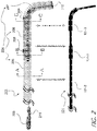
- FIG. 6 illustrates a control wire 601 of an exemplary endovascular device in accordance with the disclosure, which may be deformed or flattened in zone 601 - 3 , and may be round in other areas along its axis 601 - 2 .
- FIG. 7 illustrates an exemplary endovascular device 701 using control wire 601 in accordance with the disclosure. (Solely to illustrate the position of zones 601 - 2 and 601 - 3 in endovascular device 701 , with the understanding that control wire 601 is part of endovascular device 701 , FIG. 7 also separately depicts control wire 601 of FIG.
- endovascular device 701 may also include an elongated shaft 704 which may include a tube 705 , a cable of wires 706 , and a single wire coil 707 .
- a distal tip 710 of the elongated shaft 704 may be attached to control wire 601 , for example.
- the control wire 601 may be connected to a slider 211 of a handle 209 , with the elongated shaft 704 connected to the handle 209 to facilitate the relative movement.
- handle 209 is not depicted to the same scale as that of elongated shaft 704 .
- FIG. 8 illustrates an inner cross section D-D of a section of exemplary endovascular device 701 .
- the control wire 601 may be made from 0.14 mm Nitinol wire.
- a distal tip of the wire 601 may be gradually grinded to an outer diameter of about 70 um.
- the elongated shaft 704 may be made from a 130 cm Nitinol tube with an inner diameter of 0.18 mm which may be bonded to a PTFE covered cable of ten 70 um Nitinol wires and the distal section may be a single 70 um wire which may be coiled.
- the control wire 601 may be pressed to create flat sections 101 - 3 of about 0.16 mm ⁇ 0.12 mm of 30 mm of length.
- the cable of wires 706 and the single wire coil 707 of the elongated shaft 704 may be elliptical. This elliptical shape resists relative rotation of the elongated shaft 704 and the control wire 601 , enabling torqueing of the device.
- other non-symmetrical shapes e.g., cross-sections
- a single wire coil may be provided, extending from a multi-wire cable with a control wire that runs through the core of both. This enables the control wire to steer the more flexible coiled end of the coil, without causing the multi-wire cable to appreciably bend.
- FIG. 11A illustrates an exemplary endovascular device 1101 , according to the disclosure.
- endovascular device 1101 may also include an elongated shaft 1104 , which may include a cable of wires, including a proximal segment 1102 , at least one transition segment 1103 , and a distal segment 1105 .
- a distal tip 1110 of the elongated shaft 1104 may be attached to control wire 101 (as shown in FIG. 1 ), for example.
- the control wire 101 may be connected to a slider 211 of a handle 209 , with the elongated shaft 1104 connected to the handle 209 to facilitate the relative movement.
- handle 209 is not depicted to the same scale as that of elongated shaft 1104 .
- Hollow shaft 1104 may also include a tube (for example, tube 205 of FIG. 2 or tube 705 of FIG. 7 ), and the cable of wires may be connected to a distal end of the tube (not shown).
- the cable may include a proximal segment 1102 , at least one transition segment 1103 , and a distal segment 1105 .
- Proximal segment 1102 may be configured to transfer torque.
- a torque device such as a torquer, may be threaded over the proximal end of the elongated shaft 1104 and tightened over the proximal end of the elongated shaft 1104 .
- a rotational force exerted on the proximal end of the elongated shaft 1104 , using the torquer, may cause a rotational force to be applied to a working element located proximate the distal end of the elongated shaft 1104 .
- the ratio of the rotational force exerted on the proximal end of the elongated shaft 1104 to the rotational force applied to the working element may be approximately 1:1.
- the position of the torquer over the elongated shaft 1104 may be adjusted.
- proximal segment 1102 may be more rigid, compared to at least one transition segment 1103 and distal segment 1105 , such that proximal segment 1102 may be configured to transfer torque.
- Proximal segment 1102 may be formed of a first number of wires, and the first number of wires required to form proximal segment 1102 may be based on certain constraints. For example, certain constraints may include an outer diameter of the cable, an inner diameter of the cable, or an optimal cable angle for torque transfer.
- proximal segment 1102 may be formed of about 5-20 wires. For example, proximal segment 1102 may be formed of about 9 wires. In another example, proximal segment 1102 may be formed of about 10 wires.
- the cable may further include at least one transition segment 1103 adjacent to the proximal segment 1102 .
- Transition segment 1103 may be configured to provide a gradual transition between the proximal segment 1102 and a distal segment 1105 .
- the cable may include about 1-10 transition segments 1103 .
- the cable may include about 2 transition segments 1103 .
- the number of transition segments 1103 may vary based on various parameters, including rigidity of proximal segment 1102 , flexibility of distal segment 1105 , length of the elongated shaft 1104 , a length of the cable, or number of wires used to form the cable.
- Transition segment 1103 may be formed of about 2-19 wires.
- transition segment 1103 may be formed of about 3-6 wires.
- the number of wires used to form each transition segment 1103 may vary. For example, the number of wires used to form each transition segment may decrease as transition segment 1103 moves closer to distal segment 1105 , to thereby provide gradual increase in flexibility from proximal segment 1102 to distal segment 1105 .
- Distal segment 1105 may be configured to be atraumatic, and thus, may be configured to be very flexible. Accordingly, distal segment 1105 may be more flexible than proximal segment 1102 and at least one transition segment 1103 . In order to maintain flexibility, distal segment 1105 may be formed of about 1-5 wires. For example, distal segment 1105 may be formed of about 1-2 wires, and thus, may enable small coil winding, which may determine the flexibility of distal segment 1105 .
- proximal segment 1102 , transition segment 1103 , and distal segment 1105 appear to have a constant cable diameter in FIG. 11A
- the segments may not necessarily have a constant diameter.
- the diameter of transition segment 1103 may be smaller than the diameter of proximal segment 1102
- the diameter of distal segment 1105 may be smaller than the diameter of the transition segment 1103 .
- the diameter of hollow shaft 1104 may gradually decrease from proximal segment 1102 to distal segment 1105 .
- coil winding may decrease from proximal segment 1102 to distal segment 1105 , to thereby achieve rigidity at proximal segment 1102 , relative to distal segment 1105 , and flexibility at distal segment 1105 , relative to proximal segment 1102 .
- Rigidity may gradually decrease from proximal segment 1102 to distal segment 1105 .
- FIG. 11B illustrates section A of exemplary endovascular device 1101 of FIG. 11A , in accordance with the disclosure.
- the pitch angle at which the wires are wound may vary from proximal segment 1102 to distal segment 1105 , to thereby transfer maximum torque while maintaining tip flexibility and structural strength of endovascular device 1101 .
- proximal segment 1102 may be formed of a first number of wires wound at a first pitch angle ⁇ .
- at least one transition segment 1103 may be formed of a second number of wires (less than the first number of wires) wound at a second pitch angle ⁇ .
- distal segment 1105 may be formed of a third number of wires (less than the second number of wires) wound at a third pitch angle ⁇ .
- the pitch angle may refer to the angle, relative to the bottom planar surface of the hollow shaft 1104 , at which the wires are wound.
- the pitch angle, at which the wires are wound to form the cable may increase gradually from proximal segment 1102 to distal segment 1105 .
- pitch angle ⁇ may be smaller than pitch angle ⁇
- pitch angle ⁇ may be smaller than pitch angle ⁇ .
- Increasing the pitch angle ⁇ at distal segment 1105 may make distal segment 1105 more bendable.
- hollow shaft 1104 may include two or more transition segment 1103 at varying pitch angles.
- hollow shaft 1104 may include a first transition segment and a second transition segment, and the first transition segment may be formed of wires wound at a smaller pitch angle than the wires forming the second transition segment.
- hollow shaft 1104 may include at least three transition segments 1103 .
- the pitch angle may be determined by various parameters, including, for example, a diameter of a winding mandrel, a diameter of the wire, and a number of wires required to form each segment.
- a diameter of a winding mandrel assuming that the diameter of the wire and the initial cable diameter are known, then the diameter of the winding mandrel and the number of wires required may be calculated to obtain the optimal pitch angle. As such, the diameter of the winding mandrel may be increased or decreased to compensate for any changes in the pitch angle.
- the wires may need to be cut.
- one or more wires used to form proximal segment 1102 may be cut or removed during the winding process. Then, the remaining wires used to form proximal segment 1102 may be used to continue winding and forming transition segment 1103 .
- one or more wires used to form transition segment 1103 may be cut or removed during the winding process.
- proximal segment 1102 and transition segment 1103 may be used to continue winding and forming distal segment 1105 .
- hollow shaft 1104 includes two or more transition segments 1103 , the process may be repeated by removing more wires and continuing to wind the remaining wires to form another transition segment 1103 .
- at least one common wire may be continuously wound to form proximal segment 1102 , at least one transition segment 1103 , and distal segment 1105 . Therefore, instead of forming separate segments and connecting the segments together, the entire cable with proximal segment 1102 , at least one transition segment 1103 , and distal segment 1105 can be made with the same wire.
- the cable may be post-processed by cutting any excess wires and covering the exposed edges of the cut wires with a material 1106 .
- material 1106 used to cover exposed edges of the cut wires may include any adhesives, epoxy glues, heat shrink, polyether ether ketone (PEEK), or any other bonding material.
- the pitch angle at which the wires are wound may also change as a result, and thereby reduce the optimal torque transmission of the cable. Accordingly, a diameter of the winding mandrel may need to be adjusted in order to compensate for the wire removal.
- a diameter of the winding mandrel may need to be adjusted in order to compensate for the wire removal.
- the diameter of the winding mandrel may be decreased in order to compensate for the reduction in the number of wires used to form each segment.
- the pitch angle, at which the wires are wound to form each segment may remain optimal without any overlapping of wires.
- the pitch angle may remain constant without any overlapping of the wires.
- the diameter of the winding mandrel may be determined based on the number of wires used, the diameter of the wires, and the required pitch angle at each segment.
Landscapes
- Health & Medical Sciences (AREA)
- Life Sciences & Earth Sciences (AREA)
- Chemical & Material Sciences (AREA)
- Engineering & Computer Science (AREA)
- General Health & Medical Sciences (AREA)
- Animal Behavior & Ethology (AREA)
- Veterinary Medicine (AREA)
- Biomedical Technology (AREA)
- Heart & Thoracic Surgery (AREA)
- Public Health (AREA)
- Chemical Kinetics & Catalysis (AREA)
- Medicinal Chemistry (AREA)
- Polymers & Plastics (AREA)
- Organic Chemistry (AREA)
- Surgery (AREA)
- Biophysics (AREA)
- Pulmonology (AREA)
- Anesthesiology (AREA)
- Hematology (AREA)
- Molecular Biology (AREA)
- Medical Informatics (AREA)
- Nuclear Medicine, Radiotherapy & Molecular Imaging (AREA)
- Mechanical Engineering (AREA)
- Reproductive Health (AREA)
- Vascular Medicine (AREA)
- Media Introduction/Drainage Providing Device (AREA)
- Surgical Instruments (AREA)
Abstract
Description
Claims (9)
Priority Applications (5)
| Application Number | Priority Date | Filing Date | Title |
|---|---|---|---|
| US16/388,056 US11090464B2 (en) | 2016-09-29 | 2019-04-18 | Rotationally torquable endovascular device with actuatable working end |
| US16/668,427 US11389172B2 (en) | 2016-09-29 | 2019-10-30 | Rotationally torquable endovascular device with variable flexibility tip |
| PCT/IB2020/000286 WO2020212754A1 (en) | 2016-09-29 | 2020-04-16 | Rotationally torquable endovascular device with actuatable working end |
| US17/374,726 US20220363902A9 (en) | 2016-09-29 | 2021-07-13 | Rotationally torquable endovascular device with actuatable working end |
| US17/808,913 US20220323078A1 (en) | 2016-09-29 | 2022-06-24 | Rotationally torquable endovascular device with variable flexibility tip |
Applications Claiming Priority (3)
| Application Number | Priority Date | Filing Date | Title |
|---|---|---|---|
| US201662401387P | 2016-09-29 | 2016-09-29 | |
| PCT/IB2017/001663 WO2018060776A2 (en) | 2016-09-29 | 2017-09-28 | Rotationally torquable endovascular device with actuatable working end |
| US16/388,056 US11090464B2 (en) | 2016-09-29 | 2019-04-18 | Rotationally torquable endovascular device with actuatable working end |
Related Parent Applications (1)
| Application Number | Title | Priority Date | Filing Date |
|---|---|---|---|
| PCT/IB2017/001663 Continuation-In-Part WO2018060776A2 (en) | 2016-09-29 | 2017-09-28 | Rotationally torquable endovascular device with actuatable working end |
Related Child Applications (2)
| Application Number | Title | Priority Date | Filing Date |
|---|---|---|---|
| US16/668,427 Continuation-In-Part US11389172B2 (en) | 2016-09-29 | 2019-10-30 | Rotationally torquable endovascular device with variable flexibility tip |
| US17/374,726 Continuation US20220363902A9 (en) | 2016-09-29 | 2021-07-13 | Rotationally torquable endovascular device with actuatable working end |
Publications (2)
| Publication Number | Publication Date |
|---|---|
| US20190240457A1 US20190240457A1 (en) | 2019-08-08 |
| US11090464B2 true US11090464B2 (en) | 2021-08-17 |
Family
ID=61762557
Family Applications (3)
| Application Number | Title | Priority Date | Filing Date |
|---|---|---|---|
| US16/337,511 Active US10918834B2 (en) | 2016-09-29 | 2017-09-28 | Rotationally torquable endovascular device with actuatable working end |
| US16/388,056 Active US11090464B2 (en) | 2016-09-29 | 2019-04-18 | Rotationally torquable endovascular device with actuatable working end |
| US17/374,726 Pending US20220363902A9 (en) | 2016-09-29 | 2021-07-13 | Rotationally torquable endovascular device with actuatable working end |
Family Applications Before (1)
| Application Number | Title | Priority Date | Filing Date |
|---|---|---|---|
| US16/337,511 Active US10918834B2 (en) | 2016-09-29 | 2017-09-28 | Rotationally torquable endovascular device with actuatable working end |
Family Applications After (1)
| Application Number | Title | Priority Date | Filing Date |
|---|---|---|---|
| US17/374,726 Pending US20220363902A9 (en) | 2016-09-29 | 2021-07-13 | Rotationally torquable endovascular device with actuatable working end |
Country Status (8)
| Country | Link |
|---|---|
| US (3) | US10918834B2 (en) |
| EP (1) | EP3518835B1 (en) |
| JP (1) | JP6993408B2 (en) |
| KR (1) | KR20190064608A (en) |
| CN (1) | CN109843224B (en) |
| AU (1) | AU2017336603B2 (en) |
| IL (1) | IL265690B2 (en) |
| WO (2) | WO2018060776A2 (en) |
Families Citing this family (12)
| Publication number | Priority date | Publication date | Assignee | Title |
|---|---|---|---|---|
| JP6993408B2 (en) * | 2016-09-29 | 2022-01-13 | ラピッド メディカル リミテッド | A rotary twistable intravascular device with an operable work end |
| US11389172B2 (en) | 2016-09-29 | 2022-07-19 | Rapid Medical Ltd. | Rotationally torquable endovascular device with variable flexibility tip |
| US11395665B2 (en) | 2018-05-01 | 2022-07-26 | Incept, Llc | Devices and methods for removing obstructive material, from an intravascular site |
| JP2021522885A (en) | 2018-05-01 | 2021-09-02 | インセプト・リミテッド・ライアビリティ・カンパニーIncept,Llc | Devices and methods for removing obstructive substances from intravascular sites |
| US11471582B2 (en) | 2018-07-06 | 2022-10-18 | Incept, Llc | Vacuum transfer tool for extendable catheter |
| US11766539B2 (en) | 2019-03-29 | 2023-09-26 | Incept, Llc | Enhanced flexibility neurovascular catheter |
| US11154692B2 (en) | 2019-10-30 | 2021-10-26 | Rapid Medical Ltd. | Intraluminal device with looped core wire |
| WO2021084319A1 (en) * | 2019-10-30 | 2021-05-06 | Rapid Medical Ltd. | Rotationally torquable endovascular device with variable flexibility tip |
| US12201506B2 (en) | 2019-12-18 | 2025-01-21 | Imperative Care, Inc. | Rotatable thrombus engagement tool |
| EP4554485A1 (en) * | 2022-07-14 | 2025-05-21 | Rapid Medical Ltd. | Endovascular device |
| IL326010A (en) * | 2023-07-25 | 2026-03-01 | Rapid Medical Ltd | Guidable endovascular mesh device, and applications thereof |
| US12171917B1 (en) | 2024-01-08 | 2024-12-24 | Imperative Care, Inc. | Devices for blood capture and reintroduction during aspiration procedure |
Citations (11)
| Publication number | Priority date | Publication date | Assignee | Title |
|---|---|---|---|---|
| US4815478A (en) | 1987-02-17 | 1989-03-28 | Medtronic Versaflex, Inc. | Steerable guidewire with deflectable tip |
| US5318529A (en) | 1989-09-06 | 1994-06-07 | Boston Scientific Corporation | Angioplasty balloon catheter and adaptor |
| US5484409A (en) | 1989-08-25 | 1996-01-16 | Scimed Life Systems, Inc. | Intravascular catheter and method for use thereof |
| US20010044633A1 (en) | 2000-01-28 | 2001-11-22 | Klint Henrik Sonderskov | Endovascular medical device with plurality of wires |
| US6566994B1 (en) * | 1997-03-17 | 2003-05-20 | Fluke Corporation | Coil for an AC current sensor |
| US20040073141A1 (en) | 2002-08-22 | 2004-04-15 | William A. Cook Australia Pty. Ltd. | Guide wire |
| US20040082879A1 (en) * | 2000-01-28 | 2004-04-29 | Klint Henrik S. | Endovascular medical device with plurality of wires |
| US20090297582A1 (en) * | 2004-11-26 | 2009-12-03 | Biomerix Corporation | Vascular occlusion devices and methods |
| US20100249773A1 (en) | 2008-12-31 | 2010-09-30 | Ardian, Inc. | Handle assemblies for intravascular treatment devices and associated systems and methods |
| US20140207115A1 (en) | 2004-01-28 | 2014-07-24 | Applied Medical Resources Corporation | Medical tubing having variable characteristcs and method of making same |
| WO2018060776A2 (en) | 2016-09-29 | 2018-04-05 | Rapid Medical Ltd. | Rotationally torquable endovascular device with actuatable working end |
Family Cites Families (12)
| Publication number | Priority date | Publication date | Assignee | Title |
|---|---|---|---|---|
| US4955862A (en) * | 1989-05-22 | 1990-09-11 | Target Therapeutics, Inc. | Catheter and catheter/guide wire device |
| US7141024B2 (en) * | 2002-11-06 | 2006-11-28 | Benny Gaber | Maneuverable-coiled guidewire |
| US7625337B2 (en) * | 2003-01-17 | 2009-12-01 | Gore Enterprise Holdings, Inc. | Catheter assembly |
| CA2649702C (en) * | 2006-04-17 | 2014-12-09 | Microtherapeutics, Inc. | System and method for mechanically positioning intravascular implants |
| JP4682259B2 (en) * | 2006-09-08 | 2011-05-11 | エドワーズ ライフサイエンシーズ コーポレイション | Integrated heart valve delivery system |
| US20100228150A1 (en) * | 2009-03-05 | 2010-09-09 | Lake Region Medical, Inc. | Neuro guidewire |
| WO2010129075A1 (en) * | 2009-04-28 | 2010-11-11 | Avinger, Inc. | Guidewire support catheter |
| US8562592B2 (en) * | 2010-05-07 | 2013-10-22 | Ethicon Endo-Surgery, Inc. | Compound angle laparoscopic methods and devices |
| US9326872B2 (en) * | 2010-08-17 | 2016-05-03 | W. L. Gore & Associates, Inc. | Forced deployment sequence handle assembly with independent actuating mechanism |
| WO2013118105A1 (en) | 2012-02-12 | 2013-08-15 | CardioSert Ltd. | Guide wire for use with cardiovascular lesions |
| US20140052109A1 (en) * | 2012-08-19 | 2014-02-20 | Diros Technology Inc. | Steerable Multifunction Catheter Probe with High Guidability and Reversible Rigidity |
| CR20170245A (en) * | 2014-12-05 | 2017-09-14 | Edwards Lifesciences Corp | DIRIGIBLE CATETER WITH TRACTION CABLE |
-
2017
- 2017-09-28 JP JP2019516639A patent/JP6993408B2/en active Active
- 2017-09-28 WO PCT/IB2017/001663 patent/WO2018060776A2/en not_active Ceased
- 2017-09-28 IL IL265690A patent/IL265690B2/en unknown
- 2017-09-28 AU AU2017336603A patent/AU2017336603B2/en active Active
- 2017-09-28 KR KR1020197012337A patent/KR20190064608A/en not_active Withdrawn
- 2017-09-28 US US16/337,511 patent/US10918834B2/en active Active
- 2017-09-28 EP EP17855084.4A patent/EP3518835B1/en active Active
- 2017-09-28 CN CN201780060238.5A patent/CN109843224B/en active Active
-
2019
- 2019-04-18 US US16/388,056 patent/US11090464B2/en active Active
-
2020
- 2020-04-16 WO PCT/IB2020/000286 patent/WO2020212754A1/en not_active Ceased
-
2021
- 2021-07-13 US US17/374,726 patent/US20220363902A9/en active Pending
Patent Citations (11)
| Publication number | Priority date | Publication date | Assignee | Title |
|---|---|---|---|---|
| US4815478A (en) | 1987-02-17 | 1989-03-28 | Medtronic Versaflex, Inc. | Steerable guidewire with deflectable tip |
| US5484409A (en) | 1989-08-25 | 1996-01-16 | Scimed Life Systems, Inc. | Intravascular catheter and method for use thereof |
| US5318529A (en) | 1989-09-06 | 1994-06-07 | Boston Scientific Corporation | Angioplasty balloon catheter and adaptor |
| US6566994B1 (en) * | 1997-03-17 | 2003-05-20 | Fluke Corporation | Coil for an AC current sensor |
| US20010044633A1 (en) | 2000-01-28 | 2001-11-22 | Klint Henrik Sonderskov | Endovascular medical device with plurality of wires |
| US20040082879A1 (en) * | 2000-01-28 | 2004-04-29 | Klint Henrik S. | Endovascular medical device with plurality of wires |
| US20040073141A1 (en) | 2002-08-22 | 2004-04-15 | William A. Cook Australia Pty. Ltd. | Guide wire |
| US20140207115A1 (en) | 2004-01-28 | 2014-07-24 | Applied Medical Resources Corporation | Medical tubing having variable characteristcs and method of making same |
| US20090297582A1 (en) * | 2004-11-26 | 2009-12-03 | Biomerix Corporation | Vascular occlusion devices and methods |
| US20100249773A1 (en) | 2008-12-31 | 2010-09-30 | Ardian, Inc. | Handle assemblies for intravascular treatment devices and associated systems and methods |
| WO2018060776A2 (en) | 2016-09-29 | 2018-04-05 | Rapid Medical Ltd. | Rotationally torquable endovascular device with actuatable working end |
Non-Patent Citations (2)
| Title |
|---|
| International Search Report and Written Opinion of the International Searching Authority dated Aug. 6, 2020 in International Application No. PCT/IB2020/000286 (12 pages). |
| International Search Report and Written Opinion of the International Searching Authority dated Jul. 10, 2018, in International Application No. PCT/IB2017/001663 (10 pages). |
Also Published As
| Publication number | Publication date |
|---|---|
| EP3518835A2 (en) | 2019-08-07 |
| EP3518835C0 (en) | 2025-02-26 |
| EP3518835B1 (en) | 2025-02-26 |
| IL265690B2 (en) | 2024-01-01 |
| EP3518835A4 (en) | 2020-06-17 |
| IL265690A (en) | 2019-05-30 |
| US20220363902A9 (en) | 2022-11-17 |
| CN109843224A (en) | 2019-06-04 |
| JP2019528965A (en) | 2019-10-17 |
| KR20190064608A (en) | 2019-06-10 |
| US20220002547A1 (en) | 2022-01-06 |
| WO2018060776A3 (en) | 2018-09-27 |
| IL265690B1 (en) | 2023-09-01 |
| CN109843224B (en) | 2022-04-26 |
| US10918834B2 (en) | 2021-02-16 |
| JP6993408B2 (en) | 2022-01-13 |
| WO2018060776A2 (en) | 2018-04-05 |
| US20190224457A1 (en) | 2019-07-25 |
| AU2017336603B2 (en) | 2022-03-31 |
| US20190240457A1 (en) | 2019-08-08 |
| AU2017336603A1 (en) | 2019-03-28 |
| WO2020212754A1 (en) | 2020-10-22 |
Similar Documents
| Publication | Publication Date | Title |
|---|---|---|
| US11090464B2 (en) | Rotationally torquable endovascular device with actuatable working end | |
| EP3546008B1 (en) | Catheter and method for manufacturing catheter | |
| US20220323078A1 (en) | Rotationally torquable endovascular device with variable flexibility tip | |
| US10946171B2 (en) | Catheter devices and methods for making them | |
| US20170087340A1 (en) | Guidewire With Torque Transmission Element | |
| EP3254635B1 (en) | Radio-frequency ablation catheter having spiral structure, and equipment thereof | |
| US20050209557A1 (en) | Defined deflection structure | |
| JP2011529757A (en) | Catheter introducer | |
| JP2023021257A (en) | Intraluminal device with looped core wire | |
| JP5768358B2 (en) | CATHETER AND METHOD FOR PRODUCING CATHETER | |
| JP7710829B2 (en) | Shaft for catheter and method of manufacture - Patent application | |
| JP2021120013A (en) | Composite wires and related methods for use in medical procedures | |
| JP2020508151A (en) | Flexible torque cable for delivery of medical devices | |
| JP5927974B2 (en) | Medical equipment | |
| JP5946186B2 (en) | Coil body | |
| EP4166059A1 (en) | Reinforced working channel tube for an endoscope | |
| EP3331595B1 (en) | Catheter devices and methods for making them | |
| JP6079826B2 (en) | CATHETER AND METHOD FOR PRODUCING CATHETER | |
| WO2021084319A1 (en) | Rotationally torquable endovascular device with variable flexibility tip | |
| JP5672994B2 (en) | CATHETER AND METHOD FOR PRODUCING CATHETER | |
| WO2024205394A1 (en) | A catheter for delivering medical therapy to a remote site in a body | |
| JP5983722B2 (en) | CATHETER AND METHOD FOR PRODUCING CATHETER | |
| EP2893950A1 (en) | Catheter and method for manufacturing such catheter | |
| HK40076269A (en) | Catheter construction |
Legal Events
| Date | Code | Title | Description |
|---|---|---|---|
| FEPP | Fee payment procedure |
Free format text: ENTITY STATUS SET TO UNDISCOUNTED (ORIGINAL EVENT CODE: BIG.); ENTITY STATUS OF PATENT OWNER: SMALL ENTITY |
|
| AS | Assignment |
Owner name: RAPID MEDICAL LTD., ISRAEL Free format text: ASSIGNMENT OF ASSIGNORS INTEREST;ASSIGNORS:SUDIN, YURI;ECKHOUSE, RONEN;FRIEDMAN, AHARON;AND OTHERS;SIGNING DATES FROM 20190321 TO 20190417;REEL/FRAME:048958/0208 |
|
| STPP | Information on status: patent application and granting procedure in general |
Free format text: DOCKETED NEW CASE - READY FOR EXAMINATION |
|
| STPP | Information on status: patent application and granting procedure in general |
Free format text: NON FINAL ACTION MAILED |
|
| STPP | Information on status: patent application and granting procedure in general |
Free format text: RESPONSE TO NON-FINAL OFFICE ACTION ENTERED AND FORWARDED TO EXAMINER |
|
| STPP | Information on status: patent application and granting procedure in general |
Free format text: FINAL REJECTION MAILED |
|
| STPP | Information on status: patent application and granting procedure in general |
Free format text: DOCKETED NEW CASE - READY FOR EXAMINATION |
|
| STPP | Information on status: patent application and granting procedure in general |
Free format text: NOTICE OF ALLOWANCE MAILED -- APPLICATION RECEIVED IN OFFICE OF PUBLICATIONS |
|
| FEPP | Fee payment procedure |
Free format text: ENTITY STATUS SET TO SMALL (ORIGINAL EVENT CODE: SMAL); ENTITY STATUS OF PATENT OWNER: SMALL ENTITY |
|
| STPP | Information on status: patent application and granting procedure in general |
Free format text: PUBLICATIONS -- ISSUE FEE PAYMENT RECEIVED |
|
| STPP | Information on status: patent application and granting procedure in general |
Free format text: PUBLICATIONS -- ISSUE FEE PAYMENT VERIFIED |
|
| STCF | Information on status: patent grant |
Free format text: PATENTED CASE |
|
| MAFP | Maintenance fee payment |
Free format text: PAYMENT OF MAINTENANCE FEE, 4TH YR, SMALL ENTITY (ORIGINAL EVENT CODE: M2551); ENTITY STATUS OF PATENT OWNER: SMALL ENTITY Year of fee payment: 4 |
|
| AS | Assignment |
Owner name: LEUMI PARTNERS LTD., ISRAEL Free format text: SECURITY INTEREST;ASSIGNOR:RAPID MEDICAL LTD.;REEL/FRAME:073697/0603 Effective date: 20260202 |