US11089948B2 - Objective lens for an endoscope - Google Patents
Objective lens for an endoscope Download PDFInfo
- Publication number
- US11089948B2 US11089948B2 US16/008,795 US201816008795A US11089948B2 US 11089948 B2 US11089948 B2 US 11089948B2 US 201816008795 A US201816008795 A US 201816008795A US 11089948 B2 US11089948 B2 US 11089948B2
- Authority
- US
- United States
- Prior art keywords
- lens
- plane
- convex
- objective
- image
- Prior art date
- Legal status (The legal status is an assumption and is not a legal conclusion. Google has not performed a legal analysis and makes no representation as to the accuracy of the status listed.)
- Expired - Fee Related, expires
Links
Images


Classifications
-
- A—HUMAN NECESSITIES
- A61—MEDICAL OR VETERINARY SCIENCE; HYGIENE
- A61B—DIAGNOSIS; SURGERY; IDENTIFICATION
- A61B1/00—Instruments for performing medical examinations of the interior of cavities or tubes of the body by visual or photographical inspection, e.g. endoscopes; Illuminating arrangements therefor
- A61B1/00064—Constructional details of the endoscope body
- A61B1/00071—Insertion part of the endoscope body
- A61B1/0008—Insertion part of the endoscope body characterised by distal tip features
- A61B1/00096—Optical elements
-
- A—HUMAN NECESSITIES
- A61—MEDICAL OR VETERINARY SCIENCE; HYGIENE
- A61B—DIAGNOSIS; SURGERY; IDENTIFICATION
- A61B1/00—Instruments for performing medical examinations of the interior of cavities or tubes of the body by visual or photographical inspection, e.g. endoscopes; Illuminating arrangements therefor
- A61B1/00131—Accessories for endoscopes
-
- A—HUMAN NECESSITIES
- A61—MEDICAL OR VETERINARY SCIENCE; HYGIENE
- A61B—DIAGNOSIS; SURGERY; IDENTIFICATION
- A61B1/00—Instruments for performing medical examinations of the interior of cavities or tubes of the body by visual or photographical inspection, e.g. endoscopes; Illuminating arrangements therefor
- A61B1/00163—Optical arrangements
- A61B1/00174—Optical arrangements characterised by the viewing angles
- A61B1/00179—Optical arrangements characterised by the viewing angles for off-axis viewing
-
- A—HUMAN NECESSITIES
- A61—MEDICAL OR VETERINARY SCIENCE; HYGIENE
- A61B—DIAGNOSIS; SURGERY; IDENTIFICATION
- A61B1/00—Instruments for performing medical examinations of the interior of cavities or tubes of the body by visual or photographical inspection, e.g. endoscopes; Illuminating arrangements therefor
- A61B1/00163—Optical arrangements
- A61B1/00193—Optical arrangements adapted for stereoscopic vision
-
- A—HUMAN NECESSITIES
- A61—MEDICAL OR VETERINARY SCIENCE; HYGIENE
- A61B—DIAGNOSIS; SURGERY; IDENTIFICATION
- A61B1/00—Instruments for performing medical examinations of the interior of cavities or tubes of the body by visual or photographical inspection, e.g. endoscopes; Illuminating arrangements therefor
- A61B1/002—Instruments for performing medical examinations of the interior of cavities or tubes of the body by visual or photographical inspection, e.g. endoscopes; Illuminating arrangements therefor having rod-lens arrangements
-
- G—PHYSICS
- G02—OPTICS
- G02B—OPTICAL ELEMENTS, SYSTEMS OR APPARATUS
- G02B1/00—Optical elements characterised by the material of which they are made; Optical coatings for optical elements
- G02B1/10—Optical coatings produced by application to, or surface treatment of, optical elements
-
- G—PHYSICS
- G02—OPTICS
- G02B—OPTICAL ELEMENTS, SYSTEMS OR APPARATUS
- G02B13/00—Optical objectives specially designed for the purposes specified below
-
- G—PHYSICS
- G02—OPTICS
- G02B—OPTICAL ELEMENTS, SYSTEMS OR APPARATUS
- G02B23/00—Telescopes, e.g. binoculars; Periscopes; Instruments for viewing the inside of hollow bodies; Viewfinders; Optical aiming or sighting devices
- G02B23/24—Instruments or systems for viewing the inside of hollow bodies, e.g. fibrescopes
- G02B23/2407—Optical details
- G02B23/2423—Optical details of the distal end
- G02B23/243—Objectives for endoscopes
- G02B23/2438—Zoom objectives
-
- G—PHYSICS
- G02—OPTICS
- G02B—OPTICAL ELEMENTS, SYSTEMS OR APPARATUS
- G02B5/00—Optical elements other than lenses
- G02B5/04—Prisms
-
- G—PHYSICS
- G02—OPTICS
- G02B—OPTICAL ELEMENTS, SYSTEMS OR APPARATUS
- G02B1/00—Optical elements characterised by the material of which they are made; Optical coatings for optical elements
- G02B1/10—Optical coatings produced by application to, or surface treatment of, optical elements
- G02B1/11—Anti-reflection coatings
-
- G—PHYSICS
- G02—OPTICS
- G02B—OPTICAL ELEMENTS, SYSTEMS OR APPARATUS
- G02B13/00—Optical objectives specially designed for the purposes specified below
- G02B13/0095—Relay lenses or rod lenses
Definitions
- the invention relates to an objective lens for an endoscope having an object-side lens element including a plane-convex rod lens and an image-side lens element including a biconvex lens arranged at the image-side end of the objective lens. Further, the invention relates to a monocular endoscope or stereoscopic endoscope.
- Endoscopes are in particular used in minimally invasive surgery to allow the operating surgeon insight into the body region in which the operating field is situated.
- an objective lens is arranged, which collects the light originating from the object to be observed and generates a real intermediate image of the object.
- This intermediate image is transmitted by means of an optical relay system arranged downstream of the objective lens to the proximal end of the endoscope shaft.
- an eyepiece is arranged which images the real intermediate image either for the human eye or by means of a camera objective lens onto a sensor surface.
- Endoscopes in which the optical axis of object-side lens elements is angled with respect to the axis of the endoscope shaft are referred to in the following as angled-view endoscopes.
- endoscopes that only allow an observation of objects that substantially lie on the axis of the endoscope shaft are referred to as straight-view endoscopes.
- an objective lens for a straight-view endoscope which comprises two lens elements, of which the lens element arranged at the object side includes a glass rod as well as a plane-convex rod lens and the lens element arranged at the image side includes a biconvex lens.
- Document CN 105093515 A further discloses an objective lens for an angled-view endoscope. The beam deflection required for this is implemented with the aid of a prism.
- the inventive objective lens for an endoscope comprises an object-side lens element including a plane-convex rod lens and an image-side lens element including a biconvex lens arranged at the image-side end of the objective lens.
- the object-side lens element includes a plane-convex first lens and a biconcave second lens which form a front lens and are arranged in this order on the object side of the plane-convex rod lens forming a third lens.
- the image-side lens element includes a biconvex fourth lens, a concave-plane fifth lens and a biconcave sixth lens which are arranged in this order on the object side of the biconvex lens that is arranged at the image-side end of the objective lens and forms a seventh lens.
- the optical elements of the inventive objective lens advantageously interact to generate an intermediate image of high optical quality.
- the specific design of the image-side lens element generates an intermediate image with a defined negative image field curvature.
- This image field curvature can be corrected by further optical elements, in particular an optical relay system and an eyepiece, such that an image without significant image field curvature (or with a small distortion and/or free from astigmatism) is obtained.
- the objective lens according to the invention further comprises only a few components or optical component parts and thus has a simple and compact structure. As a result, a simple and compact structure with high optical quality is achieved.
- the objective lens according to the invention has a comparably small diameter, for example with a field of view (FOV) of greater than 70°.
- FOV field of view
- the biconvex fourth lens, the concave-plane fifth lens, the biconcave sixth lens and/or the biconvex seventh lens of the image-side lens element are cemented to each other.
- cemented lenses in the following also referred to as cemented elements, the production and assembly cost can be considerably reduced.
- the entire image-side lens element can be formed as one single component.
- the plane-convex first lens and the biconcave second lens of the object-side lens element are cemented to each other. These two lenses together are also referred to as front lens in the following.
- the front lens can in particular be formed as an achromatic lens.
- the biconcave second lens can be cemented to the plane-convex third lens.
- the object-side lens element can be formed as one single component.
- a prism is arranged such that it causes a beam deflection from the optical axis of the front lens to the longitudinal axis of the endoscope shaft of the endoscope, and when the prism is cemented to the plane-convex third lens.
- a prism for beam deflection are also referred to in the following as angled-view objective lenses to distinguish them from straight-view objective lenses without a prism.
- a plane-parallel glass plate which is cemented to the biconcave second lens and the prism is arranged between the biconcave second lens and the prism.
- the plane-parallel glass plate can in particular be formed such that the length of the path in glass of the angled-view objective lens is extended to the length of the path in glass of the straight-view objective lens.
- a glass rod in particular with two plane-parallel surfaces, is arranged between the front lens and the plane-convex third lens.
- the glass rod can be cemented to the plane-convex third lens and the biconcave second lens.
- the plane-convex first lens, the biconcave second lens, the glass rod and/or the plane-convex third lens of the object-side lens element and/or the prism and/or the plane-parallel glass plate and/or the biconvex fourth lens, the concave-plane fifth lens, the biconcave sixth lens and/or the biconvex seventh lens of the image-side lens element are made of flint glass.
- the plane-convex first lens, the glass rod, the plane-convex third lens, the plane-parallel glass plate, the biconvex fourth lens, the concave-plane fifth lens, the biconcave sixth lens and/or the biconvex seventh lens for example have an antireflection coating.
- the antireflection coating serves to reduce scattered light and an associated deterioration of the optical quality of the objective lens. Further, the antireflection coating also increases the optical transmission.
- the prism in particular has a high-reflection coating on those surfaces on which light is reflected for beam deflection. Such a coating reduces light loss by means of transmission upon reflection.
- the plane-convex first lens, the biconcave second lens, the prism and/or the plane-parallel glass plate are surrounded by a material such that the respective diameter of the element is matched to the diameter of the plane-convex third lens and/or the glass rod.
- the optical component parts of the objective lens have a common diameter, which facilitates the assembly and increases the optical and mechanical stability.
- a plane-parallel disk is arranged, which is, for example, made of sapphire.
- the use of sapphire is advantageous owing to its optical properties, in particular the high transmission level in the relevant wavelengths, its chemical properties (in particular sapphire is chemically inert) and its mechanical properties, in particular its scratch and wear resistance.
- the objective lens has a mechanical separation point between the object-side lens element and the image-side lens element.
- the mechanical separation point makes it possible to replace the object-side lens element in a particularly easy manner by an otherwise formed object-side lens element.
- the invention further relates to a stereoscopic objective lens for use in a stereoscopic endoscope.
- the stereoscopic objective lens comprises two objective lenses of the above-described type.
- a further aspect of the invention relates to a monocular endoscope or stereoscopic endoscope.
- the monocular endoscope comprises an objective lens as previously described.
- the stereoscopic endoscope comprises the just mentioned stereoscopic objective lens.
- FIG. 1 shows an embodiment of an objective lens for an endoscope
- FIG. 2 shows an embodiment of an image-side lens element for the objective lens according to FIG. 1 ;
- FIG. 3 shows an embodiment of a monocular endoscope including an objective lens according to FIG. 1 ;
- FIG. 4 shows an embodiment of a stereoscopic endoscope including two objective lenses according to FIG. 1 .
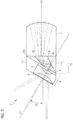
- FIG. 1 shows an embodiment of an objective lens 1 for an endoscope 24 , 25 in a schematic illustration.
- the objective lens 1 is a straight-view objective lens, i.e. the shown embodiment is suited for observing objects which substantially lie on an axis O 1 of an endoscope shaft not shown in FIG. 1 .
- the objective lens 1 includes a lens element 2 arranged on the object side and a lens element 3 arranged on the image side.
- the object-side lens element 2 is separated from the image-side lens element by a mechanical separation point 22 .
- the object-side lens element 2 comprises a front lens 4 , a glass rod 14 with two plane-parallel surfaces and a plane-convex third lens 7 formed as a rod lens.
- the front lens 4 is formed by a plane-convex first lens 5 and a biconcave second lens 6 .
- the two lenses 5 , 6 of the front lens 4 are cemented to each other.
- the front lens 4 is cemented to the glass rod 14 .
- the glass rod 14 is cemented to the plane-convex third lens 7 so that the object-side lens element 2 forms one single component part.
- a sapphire glass window 17 is arranged on the object side of the front lens 4 .
- the image-side lens element 3 comprises a first lens group 8 and a second lens group 11 .
- the first lens group 8 comprises a biconvex fourth lens 9 and a concave-plane fifth lens 10 which are cemented to each other.
- the second lens group 11 comprises a biconcave sixth lens 12 and a biconvex seventh lens 13 which are likewise cemented to each other.
- the two lens groups 8 , 11 of the image-side lens element 3 are connected to each other by cementing the concave-plane fifth lens 10 and the biconcave sixth lens 12 so that the image-side lens element 3 forms one single component part.
- the two lens groups 8 , 11 of the image-side lens element 3 are not cemented.
- the front lens 4 , the plane-convex third lens 7 , the biconvex fourth lens 9 of the first lens group 8 , the concave-plane fifth lens 10 of the first lens group 8 and the biconvex seventh lens 13 of the second lens group 11 have an antireflection coating 18 on the non-cemented surfaces.
- the objective lens 1 has blackened surfaces 19 on the biconcave second lens 6 and the concave-plane fifth lens 10 .
- the plane-convex first lens 5 and the biconcave second lens 6 are surrounded by a material 33 such that the respective diameter of the element is matched to the diameter of the plane-convex third lens 7 and/or the glass rod 14 .
- the first lens group 8 and the second lens group 11 of the image-side lens element 3 form, if taken alone, one achromatic field lens each.
- the image-side lens element 3 generates a chromatically corrected intermediate image 31 with a defined, negative image field curvature.
- the mechanical separation point 22 allows the easy exchange of the object-side lens element 2 .
- the blackened surfaces 19 have the effect of stops in the objective lens 1 (in particular each time as a stop for scattered light minimization and not as a field stop or aperture).
- Table 1 shows the lens data of the objective lens 1 according to FIG. 1 .
- the optically effective surfaces are numbered in Table 1 with 1 to 10 from the object side. All length information is expressed in the unit [mm].
- the names of the glasses are in accordance with the nomenclature of Schott.
- FIG. 2 shows an embodiment of the object-side lens element 2 for the objective lens 1 according to FIG. 1 .
- the object-side lens element 2 shown in FIG. 2 is suitable for use in an angled-view objective lens.
- the objective-side lens element 2 according to FIG. 2 differs from the object-side lens element 2 according to FIG. 1 substantially by a prism 15 arranged between the front lens 4 and the plane-convex third lens 7 .
- the object-side lens element 2 comprises a plane-parallel glass plate 16 which is arranged between the front lens 4 and the prism 15 .
- the prism 15 is formed by three elements 15 a , 15 b , 15 c , only one ( 15 b ) of which being optically effective.
- the surfaces of the prism 15 that reflect light entering into the objective lens 1 for example have a high-reflection coating 20 .
- the two outer elements 15 a , 15 c on the contrary, have a lower fraction index than the inner element 15 b , as a result whereof a total reflection at the boundary interfaces can be realized.
- a high-reflection coating is thus not absolutely necessary in the embodiment according to claim 1 .
- the plane-convex first lens 5 , the biconcave second lens 6 , the prism 15 and the plane-parallel glass plate 16 are surrounded by the material 33 such that the respective diameter of the element is matched to the diameter of the plane-convex third lens 7 .
- the prism 15 implements a beam deflection from the optical axis O 2 of the front lens 4 to the axis O 1 of the endoscope shaft not shown in FIG. 2 .
- the tilt enables an observation of objects that do not lie on the axis O 1 of the endoscope shaft.
- a tilt of the axes by 30° is exemplarily shown, but also other tilt angles are conceivable, for example 15°, 45° or 90°.
- the plane-parallel glass plate 16 provides that the length of the path in glass of the object-side lens element 2 according to FIG. 2 corresponds to the length of the path in glass of the object-side lens element 2 according to FIG. 1 .
- the path in glass in particular corresponds to the path that is covered by the light within the optical element.
- the image-side lens element 3 shown in FIG. 1 can be used together with the respective object-side lens element 2 .
- the mechanical separation point 22 of the objective lens 1 according to FIG. 1 allows the exchange of the object-side lens element 2 of the objective lens 1 , for example by the object-side lens element 2 according to FIG. 2 , to implement an endoscope 24 with angled view.
- the endoscope 24 can thus easily be adapted to different needs.
- FIG. 3 an embodiment of a monocular endoscope 24 is shown, which includes the objective lens 1 according to FIG. 1 .
- the monocular endoscope 24 comprises an objective lens 1 , an optical relay system 28 with a relay module 27 with several relay module components 27 a to 27 e and an eyepiece 26 .
- the endoscope 24 has a shaft 30 , in which the afore-mentioned elements are arranged.
- the objective lens 1 arranged at the distal end of the endoscope 24 generates a first intermediate image 31 of the object to be observed.
- the relay system 27 images the distal first intermediate image 31 onto a proximal second intermediate image 32 .
- the relay system 27 transfers the first intermediate image 31 so to speak from the distal to the proximal end of the endoscope 24 .
- the eyepiece 26 arranged at the proximal end of the endoscope 24 finally images the second intermediate image 32 onto a camera sensor not shown in FIG. 3 .
- the distal intermediate image 31 generated by the objective lens 1 has a negative image field curvature.
- the optical relay system 28 is designed to correct the negative image field curvature of the objective lens 1 .
- the image of the endoscope 24 thus has no or only a negligible image field curvature with a compact structure of all optical component parts.
- FIG. 4 An embodiment of a stereoscopic endoscope 25 is schematically illustrated in FIG. 4 .
- the stereoscopic endoscope 25 has two optical channels.
- the stereoscopic endoscope 25 has a shaft 30 in which, as viewed from the distal end, an objective lens 23 , an optical relay system 28 with two relay modules 27 for each of the two optical channels (stereoscopic relay system) and a proximally arranged eyepiece 29 are arranged.
- the objective lens 23 is formed by two objective lenses 1 according to FIG. 1 .
- One of the two objective lenses 1 each is assigned to one of the optical channels.
- Each of the two objective lenses 1 generates a first intermediate image 31 from the object to be observed.
- the stereoscopic relay system 28 according to FIG. 2 images one of the two distal intermediate images 31 each on one of the two proximal intermediate images 32 each.
- the proximal intermediate images 32 generated in this way are then imaged onto a camera sensor not shown in FIG. 4 by the eyepiece 29 .
Landscapes
- Health & Medical Sciences (AREA)
- Life Sciences & Earth Sciences (AREA)
- Physics & Mathematics (AREA)
- Surgery (AREA)
- Optics & Photonics (AREA)
- Biomedical Technology (AREA)
- Public Health (AREA)
- Nuclear Medicine, Radiotherapy & Molecular Imaging (AREA)
- Pathology (AREA)
- Radiology & Medical Imaging (AREA)
- Veterinary Medicine (AREA)
- Engineering & Computer Science (AREA)
- Heart & Thoracic Surgery (AREA)
- Biophysics (AREA)
- Molecular Biology (AREA)
- Medical Informatics (AREA)
- Animal Behavior & Ethology (AREA)
- General Health & Medical Sciences (AREA)
- General Physics & Mathematics (AREA)
- Astronomy & Astrophysics (AREA)
- Lenses (AREA)
- Endoscopes (AREA)
- Instruments For Viewing The Inside Of Hollow Bodies (AREA)
Abstract
Description
| TABLE 1 | ||||
| Surface | Radius | Thickness | Glass | Diameter |
| Object | Indefinite | 50 | 74.43 | |
| 1 | Indefinite | 0.5 | N-LASF46A | 2.8 |
| 2 | −2.84 | 0.3 | N-BAF4 | 2.8 |
| 3 | 8.85 | 0.368 | 1.4 | |
| 4 | Indefinite | 7.3 | N-LASF44 | 3.6 |
| 5 | −3.15 | 0.306 | 3.6 | |
| 6 | 5.4 | 1.4 | N-LAF21 | 3.6 |
| 7 | −3.7 | 0.7 | N-SF6 | 3.6 |
| 8 | Indefinite | 0.447 | 3.6 | |
| 9 | −2.92 | 1.1 | N-SF1 | 3.6 |
| 10 | 2.92 | 2.5 | N-LASF31 | 3.6 |
| TABLE 2 | |||
| Focal length | 1.91 mm | ||
| NA | 0.086 | ||
| Field angle | 72 | ||
| ø Image (diagonal) | 2.50 mm | ||
| Radius of the image field curvature | −2.65 mm | ||
| ø Optical system | 3.60 mm | ||
Claims (15)
Applications Claiming Priority (2)
| Application Number | Priority Date | Filing Date | Title |
|---|---|---|---|
| DE102017113273.2 | 2017-06-16 | ||
| DE102017113273.2A DE102017113273A1 (en) | 2017-06-16 | 2017-06-16 | Lens for an endoscope and endoscope |
Publications (2)
| Publication Number | Publication Date |
|---|---|
| US20180360298A1 US20180360298A1 (en) | 2018-12-20 |
| US11089948B2 true US11089948B2 (en) | 2021-08-17 |
Family
ID=62567434
Family Applications (1)
| Application Number | Title | Priority Date | Filing Date |
|---|---|---|---|
| US16/008,795 Expired - Fee Related US11089948B2 (en) | 2017-06-16 | 2018-06-14 | Objective lens for an endoscope |
Country Status (7)
| Country | Link |
|---|---|
| US (1) | US11089948B2 (en) |
| EP (1) | EP3415970B1 (en) |
| JP (1) | JP2019032510A (en) |
| CN (1) | CN109143538B (en) |
| CA (1) | CA3007263A1 (en) |
| DE (1) | DE102017113273A1 (en) |
| RU (1) | RU2764863C2 (en) |
Cited By (1)
| Publication number | Priority date | Publication date | Assignee | Title |
|---|---|---|---|---|
| US12306394B2 (en) | 2019-11-11 | 2025-05-20 | Olympus Corporation | Objective optical system, method of manufacturing objective optical system image pickup apparatus, and endoscope |
Families Citing this family (14)
| Publication number | Priority date | Publication date | Assignee | Title |
|---|---|---|---|---|
| DE102018105845A1 (en) * | 2018-03-14 | 2019-09-19 | Olympus Winter & Ibe Gmbh | Holder for an optical system of an endoscope and method for producing a holder for an optical system of an endoscope |
| WO2019193933A1 (en) * | 2018-04-02 | 2019-10-10 | オリンパス株式会社 | Light path deflection prism for endoscope, and oblique-viewing endoscope optical system |
| CN111443457B (en) * | 2019-01-16 | 2023-01-03 | 富士胶片株式会社 | Objective lens for endoscope and endoscope |
| EP3811843A1 (en) * | 2019-10-21 | 2021-04-28 | Ulrich Weiger | Endoscope |
| CN110850560B (en) * | 2019-12-24 | 2024-07-19 | 厦门力鼎光电股份有限公司 | Optical lens |
| CN111123483B (en) * | 2020-01-21 | 2024-08-20 | 厦门力鼎光电股份有限公司 | Optical imaging lens |
| CN111053523B (en) * | 2020-02-17 | 2022-04-22 | 青岛奥美克医疗科技有限公司 | Device of antifogging endoscope system |
| CN111175953B (en) * | 2020-03-06 | 2024-10-18 | 厦门力鼎光电股份有限公司 | Ultra-small zoom lens |
| CN111722378B (en) * | 2020-07-31 | 2024-07-19 | 厦门力鼎光电股份有限公司 | A fisheye lens with large image area and high resolution |
| CN112155498A (en) * | 2020-09-30 | 2021-01-01 | 山东威高手术机器人有限公司 | Stereoscopic endoscope optical system |
| CN114200662B (en) * | 2021-12-21 | 2024-06-14 | 湖南华南光电(集团)有限责任公司 | Athermal infrared sight optical system |
| DE102021134563A1 (en) * | 2021-12-23 | 2023-06-29 | Karl Storz Se & Co. Kg | Device, system and method for cleaning and/or drying an endoscope |
| CN115407491B (en) * | 2022-09-30 | 2024-07-19 | 厦门力鼎光电股份有限公司 | Optical imaging lens with wide angle and near object distance |
| CN115524833B (en) * | 2022-10-31 | 2024-06-25 | 厦门力鼎光电股份有限公司 | An optical imaging lens |
Citations (28)
| Publication number | Priority date | Publication date | Assignee | Title |
|---|---|---|---|---|
| US4178075A (en) * | 1977-02-10 | 1979-12-11 | Pilkington P. E. Limited | Lenses with distortion |
| US4621910A (en) | 1983-06-08 | 1986-11-11 | Olympus Optical Co., Ltd. | Objective for an endoscope |
| US4838247A (en) * | 1988-10-06 | 1989-06-13 | Baxter International, Inc. | Dual-view arthroscope |
| US4850342A (en) * | 1982-05-01 | 1989-07-25 | Olympus Optical Co., Ltd. | Hard endoscope of oblique view type |
| US5005957A (en) * | 1988-09-07 | 1991-04-09 | Olympus Optical Co., Ltd. | Objective lens system for endoscopes |
| US5051824A (en) * | 1989-10-30 | 1991-09-24 | Olympus Optical Co., Ltd. | Electronic scope having detachable frame to which solid state imaging device is fastened |
| JPH05297272A (en) | 1992-04-15 | 1993-11-12 | Olympus Optical Co Ltd | Objective optical system for hard endoscope |
| US5377669A (en) | 1992-04-06 | 1995-01-03 | Henke-Sass, Wolf Gmbh | Sapphire protective covering for medical endoscope |
| US5538497A (en) * | 1992-10-28 | 1996-07-23 | Oktas | Endoscope having parasitic light elements |
| US5554100A (en) * | 1994-03-24 | 1996-09-10 | United States Surgical Corporation | Arthroscope with shim for angularly orienting illumination fibers |
| US5599278A (en) * | 1994-03-15 | 1997-02-04 | Erich M. N. Hibbard | Autoclavable rigid endoscope |
| US5689365A (en) * | 1994-09-13 | 1997-11-18 | Olympus Optical Co., Ltd | Stereoscopic-vision endoscope |
| US5825534A (en) * | 1992-04-28 | 1998-10-20 | Carl-Zeiss-Stiftung | Stereoendoscope having a folded sight line |
| US5980453A (en) * | 1996-02-22 | 1999-11-09 | Precision Optics Corporation | Endoscope with low distortion |
| US6139490A (en) * | 1996-02-22 | 2000-10-31 | Precision Optics Corporation | Stereoscopic endoscope with virtual reality viewing |
| US6248060B1 (en) * | 1996-08-12 | 2001-06-19 | Mgb Endoskopische Geraete Gmbh Berlin | Rigid endoscope with second illumination system laterally offset from first illumination system |
| US20020091305A1 (en) * | 1999-06-25 | 2002-07-11 | Frank Lederer | Endoscope with a deflection system |
| US20030083551A1 (en) * | 2001-10-31 | 2003-05-01 | Susumu Takahashi | Optical observation device and 3-D image input optical system therefor |
| US6618207B2 (en) * | 1998-12-18 | 2003-09-09 | Karl Storz Gmbh & Co. Kg | Endoscope lens, and an endoscope equipped with such a lens |
| US7160247B2 (en) * | 2004-05-12 | 2007-01-09 | Linvatec Corporation | Endoscope with large diameter distal end |
| US20090203963A1 (en) | 2008-02-12 | 2009-08-13 | Olympus Medical Systems Corp. | Reimaging optical system and endoscope using the same |
| US7708689B2 (en) * | 2004-05-12 | 2010-05-04 | Linvatec Corporation | Endoscope and related system |
| US8366611B2 (en) * | 2008-12-18 | 2013-02-05 | Henke-Sass, Wolf Gmbh | Endoscope with sealing ring |
| CN105093515A (en) | 2015-09-13 | 2015-11-25 | 天津市希统电子设备有限公司 | Small-distortion large-view-field stereoscopic endoscope objective structure |
| US20170119238A1 (en) * | 2015-10-28 | 2017-05-04 | Ricoh Company, Ltd. | Optical Design of a Light Field Otoscope |
| US20170235120A1 (en) * | 2016-02-12 | 2017-08-17 | Nikon Corporation | Non-telecentric multispectral stereoscopic endoscope objective |
| US10054772B1 (en) * | 2013-01-24 | 2018-08-21 | Integrated Medical Systems International, Inc. | Diffraction limited endoscope |
| US10725282B2 (en) * | 2016-11-22 | 2020-07-28 | Karl Storz Se & Co. Kg | Negative lens and endoscope objective |
Family Cites Families (17)
| Publication number | Priority date | Publication date | Assignee | Title |
|---|---|---|---|---|
| JPS61184513A (en) * | 1984-10-02 | 1986-08-18 | Olympus Optical Co Ltd | Image transmitting optical system |
| US5632718A (en) * | 1994-03-11 | 1997-05-27 | Olympus Optical Co., Ltd. | Non-flexible endoscope with objective lens system and relay lens system |
| JPH11281887A (en) * | 1998-03-26 | 1999-10-15 | Olympus Optical Co Ltd | Solid tube optical system |
| CN100468119C (en) * | 2007-04-29 | 2009-03-11 | 上海微电子装备有限公司 | A total refraction projection optical system |
| JP5449947B2 (en) * | 2009-09-25 | 2014-03-19 | オリンパス株式会社 | Objective optical system |
| US8780463B2 (en) * | 2010-06-24 | 2014-07-15 | Ricoh Company, Ltd. | Image-forming lens, and imaging apparatus and information device using the image-forming lens |
| EP2635932B1 (en) * | 2010-10-28 | 2019-06-05 | EndoChoice Innovation Center Ltd. | Optical systems for multi-sensor endoscopes |
| US8390942B2 (en) * | 2011-01-11 | 2013-03-05 | Omnivision Technologies, Inc. | Optical lens module |
| RU113376U1 (en) * | 2011-09-15 | 2012-02-10 | Государственное образовательное учреждение высшего профессионального образования "Санкт-Петербургский государственный университет информационных технологий, механики и оптики" | STEREOSCOPIC VIDEO ENDOSCOPE |
| WO2014054407A1 (en) * | 2012-10-02 | 2014-04-10 | オリンパスメディカルシステムズ株式会社 | Endoscope objective optical system |
| EA021664B1 (en) * | 2012-12-12 | 2015-08-31 | Научно-Производственное Унитарное Предприятие "Научно-Технический Центр "Лэмт" Беломо" | Reflex lens |
| WO2014129089A1 (en) * | 2013-02-22 | 2014-08-28 | オリンパスメディカルシステムズ株式会社 | Endoscope objective optical system, and imaging device |
| DE102013215422B4 (en) * | 2013-08-06 | 2022-02-24 | Olympus Winter & Ibe Gmbh | Optical system of a stereo video endoscope with side view and stereo video endoscope with side view |
| WO2015025843A1 (en) * | 2013-08-22 | 2015-02-26 | オリンパスメディカルシステムズ株式会社 | Endoscope objective optical system |
| EP3168668A4 (en) * | 2014-07-11 | 2018-03-07 | Olympus Corporation | Objective optical system |
| DE102014117408A1 (en) * | 2014-11-27 | 2016-06-02 | avateramedical GmBH | Device for robotic surgery |
| CN106842548B (en) * | 2017-02-24 | 2023-04-28 | 东莞市宇光光电科技有限公司 | Camera Objective Optical System for Endoscopy |
-
2017
- 2017-06-16 DE DE102017113273.2A patent/DE102017113273A1/en not_active Withdrawn
-
2018
- 2018-06-05 CA CA3007263A patent/CA3007263A1/en active Pending
- 2018-06-07 EP EP18176480.4A patent/EP3415970B1/en active Active
- 2018-06-12 CN CN201810600774.6A patent/CN109143538B/en not_active Expired - Fee Related
- 2018-06-13 JP JP2018113026A patent/JP2019032510A/en active Pending
- 2018-06-14 RU RU2018121713A patent/RU2764863C2/en active
- 2018-06-14 US US16/008,795 patent/US11089948B2/en not_active Expired - Fee Related
Patent Citations (28)
| Publication number | Priority date | Publication date | Assignee | Title |
|---|---|---|---|---|
| US4178075A (en) * | 1977-02-10 | 1979-12-11 | Pilkington P. E. Limited | Lenses with distortion |
| US4850342A (en) * | 1982-05-01 | 1989-07-25 | Olympus Optical Co., Ltd. | Hard endoscope of oblique view type |
| US4621910A (en) | 1983-06-08 | 1986-11-11 | Olympus Optical Co., Ltd. | Objective for an endoscope |
| US5005957A (en) * | 1988-09-07 | 1991-04-09 | Olympus Optical Co., Ltd. | Objective lens system for endoscopes |
| US4838247A (en) * | 1988-10-06 | 1989-06-13 | Baxter International, Inc. | Dual-view arthroscope |
| US5051824A (en) * | 1989-10-30 | 1991-09-24 | Olympus Optical Co., Ltd. | Electronic scope having detachable frame to which solid state imaging device is fastened |
| US5377669A (en) | 1992-04-06 | 1995-01-03 | Henke-Sass, Wolf Gmbh | Sapphire protective covering for medical endoscope |
| JPH05297272A (en) | 1992-04-15 | 1993-11-12 | Olympus Optical Co Ltd | Objective optical system for hard endoscope |
| US5825534A (en) * | 1992-04-28 | 1998-10-20 | Carl-Zeiss-Stiftung | Stereoendoscope having a folded sight line |
| US5538497A (en) * | 1992-10-28 | 1996-07-23 | Oktas | Endoscope having parasitic light elements |
| US5599278A (en) * | 1994-03-15 | 1997-02-04 | Erich M. N. Hibbard | Autoclavable rigid endoscope |
| US5554100A (en) * | 1994-03-24 | 1996-09-10 | United States Surgical Corporation | Arthroscope with shim for angularly orienting illumination fibers |
| US5689365A (en) * | 1994-09-13 | 1997-11-18 | Olympus Optical Co., Ltd | Stereoscopic-vision endoscope |
| US6139490A (en) * | 1996-02-22 | 2000-10-31 | Precision Optics Corporation | Stereoscopic endoscope with virtual reality viewing |
| US5980453A (en) * | 1996-02-22 | 1999-11-09 | Precision Optics Corporation | Endoscope with low distortion |
| US6248060B1 (en) * | 1996-08-12 | 2001-06-19 | Mgb Endoskopische Geraete Gmbh Berlin | Rigid endoscope with second illumination system laterally offset from first illumination system |
| US6618207B2 (en) * | 1998-12-18 | 2003-09-09 | Karl Storz Gmbh & Co. Kg | Endoscope lens, and an endoscope equipped with such a lens |
| US20020091305A1 (en) * | 1999-06-25 | 2002-07-11 | Frank Lederer | Endoscope with a deflection system |
| US20030083551A1 (en) * | 2001-10-31 | 2003-05-01 | Susumu Takahashi | Optical observation device and 3-D image input optical system therefor |
| US7708689B2 (en) * | 2004-05-12 | 2010-05-04 | Linvatec Corporation | Endoscope and related system |
| US7160247B2 (en) * | 2004-05-12 | 2007-01-09 | Linvatec Corporation | Endoscope with large diameter distal end |
| US20090203963A1 (en) | 2008-02-12 | 2009-08-13 | Olympus Medical Systems Corp. | Reimaging optical system and endoscope using the same |
| US8366611B2 (en) * | 2008-12-18 | 2013-02-05 | Henke-Sass, Wolf Gmbh | Endoscope with sealing ring |
| US10054772B1 (en) * | 2013-01-24 | 2018-08-21 | Integrated Medical Systems International, Inc. | Diffraction limited endoscope |
| CN105093515A (en) | 2015-09-13 | 2015-11-25 | 天津市希统电子设备有限公司 | Small-distortion large-view-field stereoscopic endoscope objective structure |
| US20170119238A1 (en) * | 2015-10-28 | 2017-05-04 | Ricoh Company, Ltd. | Optical Design of a Light Field Otoscope |
| US20170235120A1 (en) * | 2016-02-12 | 2017-08-17 | Nikon Corporation | Non-telecentric multispectral stereoscopic endoscope objective |
| US10725282B2 (en) * | 2016-11-22 | 2020-07-28 | Karl Storz Se & Co. Kg | Negative lens and endoscope objective |
Cited By (1)
| Publication number | Priority date | Publication date | Assignee | Title |
|---|---|---|---|---|
| US12306394B2 (en) | 2019-11-11 | 2025-05-20 | Olympus Corporation | Objective optical system, method of manufacturing objective optical system image pickup apparatus, and endoscope |
Also Published As
| Publication number | Publication date |
|---|---|
| US20180360298A1 (en) | 2018-12-20 |
| CN109143538B (en) | 2022-03-04 |
| RU2018121713A (en) | 2019-12-16 |
| CA3007263A1 (en) | 2018-12-16 |
| EP3415970A1 (en) | 2018-12-19 |
| CN109143538A (en) | 2019-01-04 |
| EP3415970B1 (en) | 2020-03-18 |
| RU2764863C2 (en) | 2022-01-21 |
| RU2018121713A3 (en) | 2021-08-17 |
| JP2019032510A (en) | 2019-02-28 |
| DE102017113273A1 (en) | 2018-12-20 |
Similar Documents
| Publication | Publication Date | Title |
|---|---|---|
| US11089948B2 (en) | Objective lens for an endoscope | |
| US6038079A (en) | Sapphire objective system | |
| US6433937B1 (en) | Optical system | |
| CN107102433B (en) | Display system is imaged in hard pipe type endoscopic optical | |
| US10993604B2 (en) | Camera objective lens for an endoscope | |
| US9918619B2 (en) | Highly corrected relay system | |
| US10251537B2 (en) | Magnifying endoscope optical system | |
| US10816790B2 (en) | Relay optical system for a rigid endoscope | |
| US5980453A (en) | Endoscope with low distortion | |
| CN109416459A (en) | Endoscope objective optical system | |
| CN112639569A (en) | Wide-angle optical system and imaging device provided with same | |
| WO2017216969A1 (en) | Bright relay optical system, rigid scope optical system using same, and rigid scope | |
| US11249299B2 (en) | Stereoscopic vision optical system and endoscope using the same | |
| HK40001938A (en) | Objective lens for an endoscope and endoscope | |
| HK40001938B (en) | Objective lens for an endoscope and endoscope | |
| CN114637098B (en) | Objective lens structure of 8K laparoscope | |
| CN119376078A (en) | Optical imaging optics, couplers and endoscopes | |
| HK40001866A (en) | Camera objective lens for an endoscope and endoscope | |
| HK40001483B (en) | Relay optical system for a rigid endoscope and endoscope | |
| HK40001483A (en) | Relay optical system for a rigid endoscope and endoscope | |
| US20220346635A1 (en) | Endoscope | |
| HK40001866B (en) | Camera objective lens for an endoscope and endoscope | |
| CN120447177A (en) | Objective lens set, fluorescence optical system and endoscope | |
| CN119257523A (en) | Ultra-high-definition endoscope optical imaging system | |
| CN117928306A (en) | High-zoom-ratio continuous-zooming eyepiece optical system and application thereof |
Legal Events
| Date | Code | Title | Description |
|---|---|---|---|
| FEPP | Fee payment procedure |
Free format text: ENTITY STATUS SET TO UNDISCOUNTED (ORIGINAL EVENT CODE: BIG.); ENTITY STATUS OF PATENT OWNER: SMALL ENTITY |
|
| FEPP | Fee payment procedure |
Free format text: ENTITY STATUS SET TO SMALL (ORIGINAL EVENT CODE: SMAL); ENTITY STATUS OF PATENT OWNER: SMALL ENTITY |
|
| AS | Assignment |
Owner name: AVATERAMEDICAL GMBH, GERMANY Free format text: ASSIGNMENT OF ASSIGNORS INTEREST;ASSIGNORS:WEISE, FABIAN;KHETTAL, ALI, DR;REEL/FRAME:046934/0587 Effective date: 20180607 |
|
| STPP | Information on status: patent application and granting procedure in general |
Free format text: DOCKETED NEW CASE - READY FOR EXAMINATION |
|
| STPP | Information on status: patent application and granting procedure in general |
Free format text: NON FINAL ACTION MAILED |
|
| STPP | Information on status: patent application and granting procedure in general |
Free format text: FINAL REJECTION MAILED |
|
| STPP | Information on status: patent application and granting procedure in general |
Free format text: RESPONSE AFTER FINAL ACTION FORWARDED TO EXAMINER |
|
| STPP | Information on status: patent application and granting procedure in general |
Free format text: NOTICE OF ALLOWANCE MAILED -- APPLICATION RECEIVED IN OFFICE OF PUBLICATIONS |
|
| STPP | Information on status: patent application and granting procedure in general |
Free format text: PUBLICATIONS -- ISSUE FEE PAYMENT RECEIVED |
|
| STPP | Information on status: patent application and granting procedure in general |
Free format text: PUBLICATIONS -- ISSUE FEE PAYMENT VERIFIED |
|
| STCF | Information on status: patent grant |
Free format text: PATENTED CASE |
|
| FEPP | Fee payment procedure |
Free format text: MAINTENANCE FEE REMINDER MAILED (ORIGINAL EVENT CODE: REM.); ENTITY STATUS OF PATENT OWNER: SMALL ENTITY |
|
| LAPS | Lapse for failure to pay maintenance fees |
Free format text: PATENT EXPIRED FOR FAILURE TO PAY MAINTENANCE FEES (ORIGINAL EVENT CODE: EXP.); ENTITY STATUS OF PATENT OWNER: SMALL ENTITY |
|
| STCH | Information on status: patent discontinuation |
Free format text: PATENT EXPIRED DUE TO NONPAYMENT OF MAINTENANCE FEES UNDER 37 CFR 1.362 |
|
| FP | Lapsed due to failure to pay maintenance fee |
Effective date: 20250817 |