US11088898B2 - Updating logging behavior of a computer system using collaboration within interconnected systems - Google Patents
Updating logging behavior of a computer system using collaboration within interconnected systems Download PDFInfo
- Publication number
- US11088898B2 US11088898B2 US16/386,114 US201916386114A US11088898B2 US 11088898 B2 US11088898 B2 US 11088898B2 US 201916386114 A US201916386114 A US 201916386114A US 11088898 B2 US11088898 B2 US 11088898B2
- Authority
- US
- United States
- Prior art keywords
- parameter
- signature
- server system
- response
- function
- Prior art date
- Legal status (The legal status is an assumption and is not a legal conclusion. Google has not performed a legal analysis and makes no representation as to the accuracy of the status listed.)
- Expired - Fee Related
Links
Images


Classifications
-
- G—PHYSICS
- G06—COMPUTING OR CALCULATING; COUNTING
- G06F—ELECTRIC DIGITAL DATA PROCESSING
- G06F16/00—Information retrieval; Database structures therefor; File system structures therefor
- G06F16/90—Details of database functions independent of the retrieved data types
- G06F16/95—Retrieval from the web
- G06F16/955—Retrieval from the web using information identifiers, e.g. uniform resource locators [URL]
-
- H—ELECTRICITY
- H04—ELECTRIC COMMUNICATION TECHNIQUE
- H04L—TRANSMISSION OF DIGITAL INFORMATION, e.g. TELEGRAPHIC COMMUNICATION
- H04L41/00—Arrangements for maintenance, administration or management of data switching networks, e.g. of packet switching networks
- H04L41/06—Management of faults, events, alarms or notifications
- H04L41/069—Management of faults, events, alarms or notifications using logs of notifications; Post-processing of notifications
-
- G—PHYSICS
- G06—COMPUTING OR CALCULATING; COUNTING
- G06F—ELECTRIC DIGITAL DATA PROCESSING
- G06F16/00—Information retrieval; Database structures therefor; File system structures therefor
- G06F16/90—Details of database functions independent of the retrieved data types
- G06F16/95—Retrieval from the web
- G06F16/955—Retrieval from the web using information identifiers, e.g. uniform resource locators [URL]
- G06F16/9566—URL specific, e.g. using aliases, detecting broken or misspelled links
-
- H—ELECTRICITY
- H04—ELECTRIC COMMUNICATION TECHNIQUE
- H04L—TRANSMISSION OF DIGITAL INFORMATION, e.g. TELEGRAPHIC COMMUNICATION
- H04L67/00—Network arrangements or protocols for supporting network services or applications
- H04L67/01—Protocols
- H04L67/02—Protocols based on web technology, e.g. hypertext transfer protocol [HTTP]
-
- H—ELECTRICITY
- H04—ELECTRIC COMMUNICATION TECHNIQUE
- H04L—TRANSMISSION OF DIGITAL INFORMATION, e.g. TELEGRAPHIC COMMUNICATION
- H04L69/00—Network arrangements, protocols or services independent of the application payload and not provided for in the other groups of this subclass
- H04L69/16—Implementation or adaptation of Internet protocol [IP], of transmission control protocol [TCP] or of user datagram protocol [UDP]
Definitions
- the present invention relates to logging information for error troubleshooting, and more specifically, this invention relates to updating logging behavior of a computer system using collaboration within interconnected systems.
- a plurality of systems/components/modules are often connected/paired with one another to form a network.
- technical errors may arise.
- troubleshooting is typically performed on the system/component/module that contains the error, often using information from logs.
- a computer-implemented method includes outputting, from a requester system to a server system, a request signature.
- the request signature requests at least one parameter of a function specified in the request signature.
- the specified function exists in a functional topology of the requester system and a functional topology of the server system.
- the method further includes receiving a first response signature from the server system and identifying within the first response signature a parameter.
- the specified function is applied to the identified parameter for determining whether the identified parameter is valid.
- a location and/or an identity of the identified parameter determined to be invalid is marked in a copy of the first response signature.
- the method further includes using the functional topology of the requester system to trace and/or map the identified parameter determined to be invalid to a valid parameter, and outputting, from the requester system to the server system, a second response signature that includes the marked-up copy of the first response signature for updating logging behavior of the server system when the server system thereafter performs the specified function.
- a computer program product for enabling an updating of logging behavior of a computer system using collaboration within interconnected systems includes a computer readable storage medium having program instructions embodied therewith.
- the program instructions are readable and/or executable by a computer included in a requester system to cause the computer to perform the foregoing method.
- a system includes a processor, and logic integrated with the processor, executable by the processor, or integrated with and executable by the processor.
- the logic is configured to perform the foregoing method.
- FIG. 1 is a network architecture, in accordance with one embodiment.
- FIG. 2 is a representative hardware environment that may be associated with the servers and/or clients of FIG. 1 , in accordance with one embodiment.
- FIG. 3 is a flowchart of a method, in accordance with one embodiment.
- FIG. 4 is an architecture of interconnected systems, in accordance with one embodiment.
- FIG. 5A is a representation of a service endpoint, in accordance with one embodiment.
- FIG. 5B is a representation of a service endpoint, in accordance with one embodiment.
- FIG. 6 is a representation of formats used in an interface specification, in accordance with one embodiment.
- FIG. 7A is a functional topology of a requester system, in accordance with one embodiment.
- FIG. 7B is a functional topology of a server system, in accordance with one embodiment.
- FIG. 8 is a table in which associations between parameters and function stack calling sequences are recorded, in accordance with one embodiment.
- FIG. 9A is a table that includes service endpoint IDs and service endpoints, in accordance with one embodiment.
- FIG. 9B is a table that includes parameter set IDs, parameter sets, and service endpoints associated with the parameter sets, in accordance with one embodiment.
- FIG. 9C is a table that includes parameter IDs, parameter names, and parameter formats, in accordance with one embodiment.
- FIG. 10A is a representation of a functional topology of a requester system and a response signature generated by the requester system, in accordance with one embodiment.
- FIG. 10B is a representation of a functional topology of a server system and the response signature generated by the requester system of FIG. 10A , in accordance with one embodiment.
- FIG. 11A is a flowchart a method, in accordance with one embodiment.
- FIG. 11B is a flowchart a method, in accordance with one embodiment.
- a computer-implemented method includes outputting, from a requester system to a server system, a request signature.
- the request signature requests at least one parameter of a function specified in the request signature.
- the specified function exists in a functional topology of the requester system and a functional topology of the server system.
- the method further includes receiving a first response signature from the server system and identifying within the first response signature a parameter.
- the specified function is applied to the identified parameter for determining whether the identified parameter is valid.
- a location and/or an identity of the identified parameter determined to be invalid is marked in a copy of the first response signature.
- the method further includes using the functional topology of the requester system to trace and/or map the identified parameter determined to be invalid to a valid parameter, and outputting, from the requester system to the server system, a second response signature that includes the marked-up copy of the first response signature for updating logging behavior of the server system when the server system thereafter performs the specified function.
- the program instructions are readable and/or executable by a computer included in a requester system to cause the computer to perform the foregoing method.
- a system in another general embodiment, includes a processor, and logic integrated with the processor, executable by the processor, or integrated with and executable by the processor.
- the logic is configured to perform the foregoing method.
- FIG. 1 illustrates an architecture 100 , in accordance with one embodiment.
- a plurality of remote networks 102 are provided including a first remote network 104 and a second remote network 106 .
- a gateway 101 may be coupled between the remote networks 102 and a proximate network 108 .
- the networks 104 , 106 may each take any form including, but not limited to a local area network (LAN), a wide area network (WAN) such as the Internet, public switched telephone network (PSTN), internal telephone network, etc.
- LAN local area network
- WAN wide area network
- PSTN public switched telephone network
- the gateway 101 serves as an entrance point from the remote networks 102 to the proximate network 108 .
- the gateway 101 may function as a router, which is capable of directing a given packet of data that arrives at the gateway 101 , and a switch, which furnishes the actual path in and out of the gateway 101 for a given packet.
- At least one data server 114 coupled to the proximate network 108 , and which is accessible from the remote networks 102 via the gateway 101 .
- the data server(s) 114 may include any type of computing device/groupware. Coupled to each data server 114 is a plurality of user devices 116 .
- User devices 116 may also be connected directly through one of the networks 104 , 106 , 108 . Such user devices 116 may include a desktop computer, lap-top computer, hand-held computer, printer or any other type of logic.
- a user device 111 may also be directly coupled to any of the networks, in one embodiment.
- a peripheral 120 or series of peripherals 120 may be coupled to one or more of the networks 104 , 106 , 108 . It should be noted that databases and/or additional components may be utilized with, or integrated into, any type of network element coupled to the networks 104 , 106 , 108 . In the context of the present description, a network element may refer to any component of a network.
- methods and systems described herein may be implemented with and/or on virtual systems and/or systems which emulate one or more other systems, such as a UNIX system which emulates an IBM z/OS environment, a UNIX system which virtually hosts a MICROSOFT WINDOWS environment, a MICROSOFT WINDOWS system which emulates an IBM z/OS environment, etc.
- This virtualization and/or emulation may be enhanced through the use of VMWARE software, in some embodiments.
- one or more networks 104 , 106 , 108 may represent a cluster of systems commonly referred to as a “cloud.”
- cloud computing shared resources, such as processing power, peripherals, software, data, servers, etc., are provided to any system in the cloud in an on-demand relationship, thereby allowing access and distribution of services across many computing systems.
- Cloud computing typically involves an Internet connection between the systems operating in the cloud, but other techniques of connecting the systems may also be used.
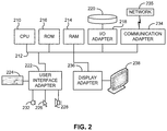
- FIG. 2 shows a representative hardware environment associated with a user device 116 and/or server 114 of FIG. 1 , in accordance with one embodiment.
- Such figure illustrates a typical hardware configuration of a workstation having a central processing unit 210 , such as a microprocessor, and a number of other units interconnected via a system bus 212 .
- a central processing unit 210 such as a microprocessor
- the workstation shown in FIG. 2 includes a Random Access Memory (RAM) 214 , Read Only Memory (ROM) 216 , an input/output (I/O) adapter 218 for connecting peripheral devices such as disk storage units 220 to the bus 212 , a user interface adapter 222 for connecting a keyboard 224 , a mouse 226 , a speaker 228 , a microphone 232 , and/or other user interface devices such as a touch screen and a digital camera (not shown) to the bus 212 , communication adapter 234 for connecting the workstation to a communication network 235 (e.g., a data processing network) and a display adapter 236 for connecting the bus 212 to a display device 238 .
- RAM Random Access Memory
- ROM Read Only Memory
- I/O input/output
- I/O input/output
- peripheral devices such as disk storage units 220
- a user interface adapter 222 for connecting a keyboard 224 , a mouse 226 , a speaker 2
- the workstation may have resident thereon an operating system such as the Microsoft Windows® Operating System (OS), a MAC OS, a UNIX OS, etc. It will be appreciated that a preferred embodiment may also be implemented on platforms and operating systems other than those mentioned.
- OS Microsoft Windows® Operating System
- a preferred embodiment may be written using eXtensible Markup Language (XML), C, and/or C++ language, or other programming languages, along with an object oriented programming methodology.
- Object oriented programming (OOP) which has become increasingly used to develop complex applications, may be used.
- this logic may be implemented as a method on any device and/or system or as a computer program product, according to various embodiments.
- a plurality of systems/components/modules are often connected/paired with one another to form a network.
- technical errors may arise.
- troubleshooting is typically performed on the system/component/module that contains the error, often using information from logs.
- SLAs service level agreements
- FIG. 3 a flowchart of a method 300 is shown according to one embodiment.
- the method 300 may be performed in accordance with the present invention in any of the environments depicted in FIGS. 1-2, 4, 7A-7B, and 10A-10B , among others, in various embodiments.
- more or less operations than those specifically described in FIG. 3 may be included in method 300 , as would be understood by one of skill in the art upon reading the present descriptions.
- Each of the steps of the method 300 may be performed by any suitable component of the operating environment.
- the method 300 may be partially or entirely performed by a computer of interconnected systems, or some other device having one or more processors therein.
- the processor e.g., processing circuit(s), chip(s), and/or module(s) implemented in hardware and/or software, and preferably having at least one hardware component may be utilized in any device to perform one or more steps of the method 300 .
- Illustrative processors include, but are not limited to, a central processing unit (CPU), an application specific integrated circuit (ASIC), a field programmable gate array (FPGA), etc., combinations thereof, or any other suitable computing device known in the art.
- method 300 includes several operations that may be performed by a requester system 302 and several operations that may be performed by a server system 304 .
- the requester system 302 and the server system 304 may be portions of any known type of interconnected system, and are thus peers.
- the present method 300 is described as being performed between the requester system 302 and the server system 304 , in some other approaches, such a method may be performed by any number of peers (requester systems and/or server systems) in an interconnected system.
- any communication performed between the requester system 302 and the server system 304 may be at least in part based on any one or more known type of transmission protocol(s), e.g., Transmission Control Protocol/Internet Protocol (TCP/IP), HyperText Transfer Protocol (HTTP), etc.
- a server system and a requester system as used herein may each be any type of computer system known in the art and capable of communicating with the other system.
- communications between the requester system 302 and the server system 304 may in some approaches be utilized for enabling a finer and more targeted scope of logging collection of the server system 304 .
- Such approaches may specifically utilize at least one requester system, e.g., such as requester system 302 , for determining whether a scope of server system logging may be updated to, e.g., gather more logging detail to help mitigate errors output by the server system 304 , increase performance of the server system 304 by reducing logging detail, increase efficiency of a network that includes the requester system 302 and the server system 304 , etc.
- the requester system 302 is now allowed to identify the key and/or the interested element(s) for targeted logging, which can be further used to infer which scope on the server system 304 should be impacted.
- processing resources of the server system 304 that otherwise would have been consumed in determining whether a current logging scope of the server system 304 should be updated may be preserved for other uses.
- method 300 may optionally include the requester system 302 and/or the server system 304 establishing a respective functional architecture.
- method 300 may optionally include the requester system 302 pre-establishing a functional architecture of the requester system 302 , e.g., see operation 306 of method 300 .
- method 300 may optionally additionally and/or alternatively include the server system 304 pre-establishing a functional architecture of the server system 304 , e.g., see operation 308 of method 300 .
- the functional architecture of the requester system 302 and/or the functional architecture of the server system 304 may in some approaches be arranged as a logical tree, e.g., see FIGS. 7A-7B .
- the functions of the functional architectures of the systems 302 , 304 may be nodes.
- the functions of the functional architectures of the systems 302 , 304 preferably include at least one associated parameter, e.g., where each parameter and/or value/name of the parameter is logically structured as a leaf of an associated function.
- a parameter may be metadata that is pre-associated with one or more functions of a functional topology.
- each parameter and/or value/name of the parameter may be a potential answer to an associated function.
- each parameter and/or value/name of the parameter may be inferred by the server to generate a category of potential results that may occur based on the function being applied, e.g., applied by the requester system 302 and/or being applied by the server system 304 .
- each parameter may in some approaches be logically connected to an associated function by logical arches.
- the functional architecture of the requester system 302 may be relatively similar to the functional architecture of the server system 304 , but may also differ in that arches of the functional architecture of the requester system 302 may correspond to consuming functions, e.g., reading that may be performed by the requester system 302 , while and arches 722 of the functional topology 720 may correspond to updating functions, e.g., writing that may be performed by the server system 304 .
- operation 310 of method 300 includes outputting, from the requester system 302 to the server system 304 , a request signature.
- the request signature may in some approaches be, e.g., stored at one or more locations within a network that includes the requester system 302 and the server system 304 , indexed, shared, etc.
- the request signature may be output as and/or saved in a text block that concatenates a service endpoint and parameter specified in the request signature in any predetermined order.
- the request signature may be stored and indexed in a table, e.g., as will be described in greater detail elsewhere herein.
- the request signature may be generated by the requester system 302 at any time prior to be output to the server system 304 .
- the request signature may be generated by the requester system 302 , e.g., on the fly, at times predetermined by the requester system 302 , using a module of the requester system 302 that reads defined data structures of an interface specification of the requester system 302 and the server system 304 and thereby manages request signature(s) output by the requester system 302 , etc.
- the request signature may request at least one parameter of a function specified in the request signature.
- a parameter may be defined by a parameter name and/or a value.
- a parameter may be defined by a name, e.g., such as “Address Structure” (or any other description phrase).
- My_Address may be the parameter name that is explicitly mentioned and defined literally.
- the value of the parameter may be only defined with a type, e.g., in the present example the type of the value for the parameter name “My_Address” is defined as a string. Accordingly, reference herein to a “parameter”, e.g., such as the parameter of the request signature and/or the response signature(s), may in some approaches be a parameter name and/or a value.
- the specified function preferably exists in the functional topology of the requester system 302 and the functional topology of the server system 304 .
- the specified function may be any known type of function, e.g., a request for a status, a request for information stored in a table, a request for a string of information, etc.
- the request signature may additionally and/or alternatively request at least one parameter of a service endpoint specified in the request signature.
- the request signature may request all parameter names and/or values of a set of parameters that are associated with a predetermined function.
- the request signature may specify a service endpoint on the requester system 302 and/or the source system 304 that is to be used thereafter, e.g., by the server system 304 when outputting a response signature to the requester system 302 , by the requester system 302 when outputting a response signature to the requester system 302 , by the requester system 302 when outputting a subsequent request signature to the requester system 302 , etc.
- At least some communication, e.g., transactions, procedures, etc., between the requester system 302 and the server system 304 may be defined according to an interface specification of the requester system 302 and the server system 304 . Having a pre-established interface specification may allow for the handling of functions on both the requester system 302 and the server system 304 .
- the interface specification may in some approaches be of a type known in art.
- method 300 may additionally and/or alternatively include defining a known type of message format, e.g., parameter name, parameter type, parameter values, etc.
- the request signature may be output to a service endpoint of the server system 304 .
- the service endpoint may be a TCP/IP socket port of the server system 304 .
- the request signature may be output by the requester system 302 to the service endpoint, e.g., TCP/IP socket port, of the server system 304 as a serialized data stream.
- the request signature may be received by the server system 304 , e.g., see operation 312 of method 300 .
- a first response signature may be generated by the server system 304 , e.g., see operation 314 of method 300 .
- the first response signature preferably includes at least one parameter, e.g., a parameter name of a parameter associated with the function specified in the received request signature or a parameter value of a parameter associated with the function specified in the received request signature, etc.
- the request signature may be a callable service, e.g., to a service endpoint of the server system 304 with the names of the parameter(s) included in the call. In such an approach the parameter of the first response signature may define an outcome of the callable service.
- the parameter of the first response signature may, in the functional topology of the server system 304 , be incorrectly associated with the function specified in the request signature.
- the parameter of the first response signature may include an invalid parameter name and/or an invalid value.
- a determination of whether the parameter is invalid or is valid is not performed on the server system 304 .
- the parameter of the generated first response signature may be output to the requester system 302 , e.g., see operation 316 of method 300 , for performing such a determination.
- the first response signature may be received by the requester system 302 , e.g., see operation 318 of method 300 .
- the first response signature may include only the parameter that is associated with the specified function of the request signature.
- the first response signature may additionally include other information.
- Reasons for including information in addition to the parameter in the first response signature may depend on the approach, e.g., in order to encrypt the parameter in the first response signature, in order send additional requested data from the server system 304 to the requester system 302 , in order to send a batch of parameters for determining the validity of, etc.
- the requester system 302 may identify within the first response signature at least one parameter that is associated with the specified function, e.g., see operation 320 of method 300 .
- the parameter may be identified from the contents of the first response signature.
- a parameter that is associated with the specified function may be included in a set of parameters of the first response signature.
- the set of parameters of the first response signature may be configured in any one or more known formats.
- the set of parameters of the first response signature may be configured as a simple data type, e.g., a string, an integer, a float, a serialized data bit stream, etc.
- the set of parameters of the first response signature may be additionally and/or alternatively configured as a composited data type, e.g., a multi-level set of parameters, a list, a word of a dictionary file, etc.
- the request signature may be output to and/or received by a service endpoint of the server system 304 .
- the service endpoint of the server system 304 is a HTTP Uniform Resource Locator (URL).
- the first response signature includes a set of parameters.
- the parameters of the first response signature may include any one or more formats.
- the first response signature may include one or more parameters embedded in a URL string, e.g., such as value(s) and/or parameter names of the parameter embedded in the string.
- the URL may be further constituted by, e.g., a hostname of the server system 304 , a port number of the server system 304 , a relative path established between the requester system 302 and the server system 304 , etc.
- the first response signature may include one or more parameters defined in HTTP headers.
- the first response signature may include one or more parameters encoded within a predefined parameter format for HTTP body, e.g., parameters encoded within data that immediately follows HTTP headers in the first response signature.
- the first response signature may be additionally and/or alternatively configured in any type of form.
- the first response signature may be configured as a table and/or a concentrated text block.
- the first response signature may include data organized in a structure, e.g., data organized as entries in a table, data organized as entries in a list, data organized as a group of parameters, etc.
- the requester system 302 may identify the parameter within the first response signature by parsing the structured data, e.g., using known parsing and/or identification techniques.
- the structured data may be parsed for identifying a parameter that is associated with the function specified in the request signature.
- the structured data may be additionally and/or alternatively parsed for identifying a parameter that is associated with or one or more functions that exist in a same logical path of the functional topology of the requester system as a logical path of the functional topology of the requester system that the function specified in the request signature exists in, e.g., see sub-function Function- 21 of FIG. 7A which exists in a same logical path of functional topology 700 as Function- 2 .
- the first response signature may additionally and/or alternatively include subsidiary data that is affiliated with the first response signature.
- the first response signature may be encoded, e.g., include encoded data.
- the contents of the first response signature may be encoded using a known, e.g., method message body, etc., where the data of the encoded contents of the response may be configured in any known form, e.g., Comma-Separated Values (CSV), Hypertext Markup Language (HTML), Extensible Markup Language (XML), a .yml file, JavaScript Object Notation (JSON), etc.
- identifying at least one parameter that is associated with the specified function may include decoding the first response signature, e.g., using known decoding techniques.
- the specified function may be applied to the identified parameter, e.g., see operation 322 of method 300 .
- the specified function may be applied to the identified parameter for determining whether the parameter is valid, e.g., see decision 324 of method 300 .
- the specified function may be applied to the identified parameter using any one or more known techniques for causing a parameter to be consumed by a function.
- applying the specified function to the parameter may include comparing a value and/or name of the parameter to one or more parameter names and/or values that are pre-associated with/potential answers of the function specified in the request signature.
- the parameter in response to the parameter matching one of the parameters that are pre-associated with/potential answers of the function specified in the request signature, the parameter may be determined to be valid. However, in response to the identified parameter not matching any parameters of the function specified in the request signature, the parameter may be determined to be invalid. As will be described elsewhere below, in some approaches, the matching of parameters may be determined with respect to parameter name(s) and/or parameter value(s) of the identified parameter.
- an example of the parameter name of the parameter “My_Addresss, A, B, C” being invalid may include My_Address being defined as the parameter name of a parameter(Address Structure), but the response signature of the server system 304 may return “My_Addr,” which may result in a returned parameter name “UNDEFINED.” The parameter name “UNDEFINED” would be deemed an invalid parameter.
- detection of such an invalid parameter name may be detected by the requester system 302 upon the requester system 302 attempting to decode the response signature returned from the server system 304 .
- the parameter may be determined by the requester system 302 to be invalid upon an error and/or error message arising upon reading the undefined parameter “My_Addr.”
- the parameter may be additionally and/or alternatively determined by the requester system 302 to be invalid upon the requester system 302 determining that a mandatory parameter is missing from the identified parameter, e.g., the parameter name “My_Address” is not included in the identified parameter.
- an invalidity of a value of the identified parameter and thereby an invalidity of the identified parameter may be determined on an interface specification level.
- the identified parameter may be determined by the requester system 302 to be invalid upon the requester system 302 determining that the identified parameter includes a type error.
- the type error may be based on a characteristic of the interface specification, e.g., a type of the “Address Structure” is a string but the received parameter type is an integer and/or anything besides the expected string.
- the error may be a boundary error, e.g., a defined range of a parameter of the interface specification is 1-9 but the value of the identified parameter is 0 or 10.
- an invalidity of the value of the identified parameter and thereby an invalidity of the identified parameter may be determined on a detailed logical level, which may not be detectable on interface specification level.
- the value “A, B, C” included in the aforementioned identified parameter “My_Address, A, B, C” may be a string type, but the address denoted by the string may be determined by the requester system 302 to not exist.
- detecting/determining the invalidity of an identified parameter name may be performed by auditing a received response signature with a definition of the interface specification for the above mentioned “undefined” and interface specification level types of invalidity.
- detecting/determining the invalidity of an identified parameter name may include the requester system 302 detecting occurrence of a runtime error as a result of the invalidity occurring on logical level, which may be detected with a related parameter that is marked as invalid.
- applying the specified function to the parameter may include determining whether a context of the identified parameter of the first response signature matches a context of the function specified in the request signature.
- Contexts of parameters and response signatures may be any subject or type of description.
- an identified parameter may be a specific color, e.g., blue, red, yellow, etc.
- the context of the parameter may be a color.
- the function specified in the request signature may request that the server system return the name of a color. In such an example, the function specified in the request signature also has the context of color.
- a context of the identified parameter in response to determining that a context of the identified parameter is a color where the function specified in the request signature requests a color, it may be determined the context of the identified parameter and the context of the function specified in the request signature match. In response to the context of the identified parameter matching a context of the function specified in the request signature, the parameter may be determined to be valid. However, in response to determining that the contexts of the identified parameter and the function specified in the request signature do not match, the parameter may be determined to be invalid.
- a context of the function specified in the request signature may be a color, e.g., such as where the function specified in the request signature requests the color of a bus on a predetermined city route.
- the requester system may determine that a context of the first response signature (time) does not match the context of the function specified in the request signature (color). Accordingly, in such an approach, the parameter may be determined to be invalid.
- determination of whether or not a context of an identified parameter matches a context of the function specified in the request signature may include the requester system performing comparisons. For example, in one approach, a context of an identified parameter may be compared with a predefined list of potential contexts that is stored in the functional topology of the requester system, e.g., stored as potential contexts of the function specified in the request signature. Moreover, in some approaches, the requester system may identify the context of the identified parameter from the first response signature using similar techniques to those described herein for identifying a parameter(s) in a response signature, e.g., parsing, decoding, decrypting, etc.
- Method 300 may optionally include the requester system 302 generating a notification of any determination that the parameter of the first response signature is valid.
- the generated notification may be output to the server system 304 , e.g., see operation 326 of method 300 .
- the notification may be received by the server system 304 , e.g., see operation 328 , and may be stored to record the valid parameter.
- the server system 304 may not update logging behavior of the server system 304 .
- processing resources of the server system 304 may be preserved, e.g., resources of the requester system 302 are recruited for making the determination.
- the performance of the server system 304 is not reduced as might otherwise occur if the server system 304 had performed such a validity determination locally.
- the server system will understand how to correct invalid data.
- Such determinations may also be used by the server system 304 in order to understand when to update logging behavior, e.g., increase log verbosity, to facilitate error troubleshooting and when to decrease log verbosity to alleviate performance impact due to incurred resource overhead from increasing system logging.
- the requester system 302 may not notify the server system 304 of the determined validity. Accordingly, in such an approach, the server system 304 may determine, e.g., based on not receiving a second response signature from the requester system 302 , that the parameter of the first response signature is valid.
- a location and/or an identity of the identified parameter determined to be invalid may be marked in a copy of the first response signature, e.g., see operation 330 of method 300 .
- a marking may be performed in order to record the determined invalidity of the parameter stored on the server system 304 .
- the server system 304 may be informed that the parameter is invalid, e.g., so that the functional topology/logging behavior of the server system 304 may be updated to include only valid parameters.
- method 300 may additionally and/or alternatively include appending information detailing the invalidity, e.g., how such an invalidity was determined, a suggestion for how to correct the invalidity, an error processing log, etc., to the copy of the first response signature.
- the additional information may in some approaches be used by the server system 304 for amending the invalid parameter, e.g., to be a valid parameter.
- the requester system 302 may use the functional topology of the requester system 302 to trace and/or map the identified parameter determined to be invalid to a valid parameter, e.g., see operation 332 of method 300 .
- tracing and/or mapping the identified parameter determined to be invalid to a valid parameter may include performing a known type of tracing and/or auditing of the requester system 302 for determining the parameter of an original copy of the parameter previously returned by the server system 304 to the requester system 302 .
- tracing and/or mapping the identified parameter determined to be invalid to a valid parameter may include the requester system 302 communicating with another system (not shown) for determining a valid parameter for the function specified in the request signature.
- tracing and/or mapping the identified parameter determined to be invalid to a valid parameter may include determining one or more functions of a functional topology of the server system 304 that have and/or do use the invalid parameter. Such a determination may be performed by performing an audit on, e.g., the functional topology of the requester system 302 , the functional topology of the server system 304 , response signatures previously received from the server system 304 , etc.
- the requester system 302 may generate a second response signature, e.g., see operation 334 of method 300 .
- the second response signature may include the marked-up copy of the first response signature.
- the second response signature may additionally and/or alternatively include any other information associated with the determining that the parameter is invalid and/or any other information that is scheduled to be sent from the requester system 302 to the server system 304 .
- such information may include one or more functions of a functional topology of the server system 304 that is determined by the requester system 302 to use the invalid parameter.
- Operation 336 of method 300 includes outputting from the requester system 302 to the server system 304 , the second response signature with the included marked-up copy of the first response signature.
- the second response signature with the included marked-up copy of the first response signature may be output to the server system 304 for updating logging behavior of the server system 304 when the server system 304 thereafter performs the specified function of the interface specification, e.g., as will be described elsewhere herein (see operation 340 of method 300 ).
- the second response signature and/or information of the second response signature (such as the marked-up copy of the first response signature) may be configured in any format, e.g., such as those described elsewhere herein for the request signature and/or for the first response signature.
- the second response signature and the marked-up copy of the first response signature may be output to the server system 304 as a service call.
- the second response signature may be received by the server system 304 , e.g., see operation 338 of method 300 .
- the server system 304 may use the received second response signature and/or the marked-up copy of the first response signature for identifying at least one function of the server system 304 that includes the parameter identified in the marked-up copy of the first response signature to be invalid, e.g., see operation 340 of method 300 .
- identifying the function(s) of the server system 304 that includes the parameter identified in the marked-up copy of the first response signature to be invalid may include the server system 304 searching the functional topology of the server system 304 for function(s) that have the invalid parameter associated therewith and/or that have manipulated the invalid parameter, e.g., previously output the invalid parameter in another response signature.
- identifying function(s) of the server system 304 that includes the invalid parameter may include the server system 304 reformatting, e.g., decoding, decrypting, etc., the received second response signature and/or the marked-up copy of the first response signature.
- Operation 342 of method 300 includes modifying the logging behavior of the server system 304 .
- a previous verbosity of logging performed by the server system 304 may have resulted in troubleshooting performed on the server system 304 to not correct the invalid parameter.
- the logging behavior of the server system 304 may be modified in order to provide troubleshooting performed on the server system 304 with an amount of information that results in invalid data within the functional topology of the server system 304 being corrected.
- modifying the logging behavior of the server system 304 includes generating a function stack calling sequence that includes each of the function(s) identified to have the invalid parameter associated therewith and/or that have manipulated the invalid parameter.
- the logging behavior of one or more of the functions of the function stack calling sequence may in one approach be adjusted to be a predetermined target logging level, which will now be described below according to various approaches.
- a current logging behavior of the server system 304 may be set to, e.g., debug (a relatively finest degree of detail logged), informational (a relatively less fine degree of detail logged than debug), warn (a relatively less fine degree of detail logged than informational), or critical (a relatively least degree of detail logged).
- the logging behavior may reside at critical level, e.g., in order to increase performance of the server system 304 by collecting a relatively low logging detail.
- the requester system providing information to the server system 304 that indicates that troubleshooting is to be performed on the server system 304 , e.g., marked invalid parameter
- the logging behavior of one or more of the functions of the function stack calling sequence and/or one or more sub-functions that call the function may in one approach be adjusted to the predetermined target logging level, e.g., in the present example a logging behavior that logs more detail than the critical level.
- the logging behavior of the server system 304 may be adjusted from critical to informational or debug.
- the logging verbosity of the server system 304 may be increased to an even greater verbosity.
- Such a determination may be made by the requester system 302 while performing method 300 subsequent an updating of the logging behavior of the server system 304 , e.g., based on the previous updating of the logging behavior being recorded on the server system 304 .
- Modifying the logging behavior of the server system 304 may in some approaches at least in part additionally and/or alternatively depend on performance metrics of the server system 304 .
- an increasing of the verbosity of the logging behavior of the server system 304 may additionally and/or alternatively incorporate runtime server system load into consideration. For example, at least in part in response to a determination that a CPU usage of the server system 304 is below 50%, and a memory usage of the server system 304 is below 80%, the target logging level may be updated to debug. However, in another example, at least in part in response to a determination that the CPU usage of the server system 304 is between 90% and 50%, and the memory usage of the server system 304 is between 90% and 80%, the target logging level may be updated to informational.
- Such an adjustment may in some approaches include enabling logging, e.g., in other words logging may be disabled prior to the adjustment. In another approach, such an adjustment may include disabling logging. According to another approach, the logging level of one or more of the functions of the function stack calling sequence may be adjusted to be a predetermined default logging level. Various examples of modifying the logging behavior of a server system will be described in greater detail elsewhere herein, e.g., see FIGS. 11A-11B .
- Adjustment of the logging behavior of functions of the server system 304 will ensure proper logging of error(s) on the server system 304 that previously resulted in and/or would have resulted in incorrect/invalid data being output by the server system 304 in a response signature, e.g., such as the first response signature. As a result, response signatures thereafter output by the server system 304 will include valid data. However, it should be noted that such a correction of logging behavior on the server system 304 is preferably not achieved as a result of increasing processing of the server system 304 . Instead, identifying of invalid parameters is performed by the requester system 302 , and as a result processing resources of the server system 304 is preserved.
- FIG. 4 depicts an architecture 400 of interconnected systems, in accordance with one embodiment.
- the present architecture 400 may be implemented in conjunction with features from any other embodiment listed herein, such as those described with reference to the other FIGS.
- the architecture 400 and others presented herein may be used in various applications and/or in permutations which may or may not be specifically described in the illustrative embodiments listed herein.
- the architecture 400 presented herein may be used in any desired environment.
- Architecture 400 includes a requester system, e.g., requester system 402 , and a server system 404 .
- the requester system 402 (client) and the server system 404 are interconnected systems of a common network 406 . Although only two systems are shown to be in communication in the network 406 , e.g., see requester system 402 to server system 404 and server system 404 to requester system 402 communication 408 , depending on the approach, the network 406 may include any number of interconnected systems.
- the requester system 402 and/or the server system 404 may be any known type(s) of systems, and moreover may each include a process unit, e.g., a CPU, memory, storage, a network interface to enable loading of software and thereby enabling the running of predefined procedures, etc.
- a process unit e.g., a CPU, memory, storage, a network interface to enable loading of software and thereby enabling the running of predefined procedures, etc.
- Communication 408 between the requester system 402 and the server system 404 may be based on any one or more transmission protocols, e.g., TCP/IP, HTTP, etc., e.g., see FIGS. 5A-5B .
- one or more transactions between the requester system and server system may be defined according to a predefined interface specification, which may be configured for handling operations that occur on the requester system 402 and/or the server system 404 .
- the interface specification may be of a known type, and may be used for defining operations/processes that occur between interconnected nodes of the architecture 400 , e.g., the requester system 402 and the server system 404 .
- FIGS. 5A-5B depict service endpoints 500 , 520 of interconnected systems, in accordance with one embodiment.
- the present service endpoints 500 , 520 may be implemented in conjunction with features from any other embodiment listed herein, such as those described with reference to the other FIGS.
- service endpoints 500 , 520 and others presented herein may be used in various applications and/or in permutations which may or may not be specifically described in the illustrative embodiments listed herein.
- the service endpoints 500 , 520 presented herein may be used in any desired environment.
- service endpoint 500 is a TCP/IP based service endpoint that in some approaches may be used for communication between interconnected systems.
- the service endpoint 500 includes a specified TCP/IP port number 502 .
- service endpoint 520 is an HTTP based service endpoint that according to some approaches may be used for communication between interconnected systems.
- the service endpoint 520 specifies a hostname 522 , a port number 524 , and a relative path 526 to the port number 524 .
- Representation 600 of FIG. 6 depicts data formats 602 , 604 used in an interface specification of interconnected systems, in accordance with one embodiment.
- the present data formats 602 , 604 may be implemented in conjunction with features from any other embodiment listed herein, such as those described with reference to the other FIGS.
- data formats 602 , 604 and others presented herein may be used in various applications and/or in permutations which may or may not be specifically described in the illustrative embodiments listed herein.
- the data formats 602 , 604 presented herein may be used in any desired environment.
- a named data format e.g., such as data format 604
- the data format may be readily useable, e.g., not be subject to decoding, by the system receiving the request signature or response signature.
- an anonymous data format e.g., such as data format 602
- communication using an anonymous data format may include communicating using only values exchanged between a requester system and a server system.
- at least one component of the requester system and/or the source system may be used for converting received anonymous data entries into named data entries, e.g., where the names of the named data entries are defined in and thereby converted using an interface specification known to the requester system and a server system.
- FIGS. 7A-7B depict functional topologies 700 , 720 , in accordance with one embodiment.
- the present functional topologies 700 , 720 may be implemented in conjunction with features from any other embodiment listed herein, such as those described with reference to the other FIGS.
- Such functional topologies 700 , 720 and others presented herein may be used in various applications and/or in permutations which may or may not be specifically described in the illustrative embodiments listed herein.
- the functional topologies 700 , 720 presented herein may be used in any desired environment.
- a request signature output from a requester system to a server system may request at least one parameter of a function specified in the request signature.
- the specified function may exist in a functional topology of the requester system and a functional topology of the server system.
- the functional topology 700 is a functional topology of a requester system.
- the functional topology 700 may be generated by the requester system.
- the functional topology 720 is a functional topology of a server system.
- the functional topology 720 may be generated by the server system.
- the functional topologies 700 , 720 may include any number of functions, e.g., see Function- 1 , Function- 2 , Function- 21 , . . . , Function-N. Each of the functions may have at least one significant data entry associated therewith, e.g., parameter in the current approach. Each parameter may specify a predetermined name and/or type of data in accordance with the interface specification. For example, parameters PN- 1 , PN- 2 are each associated with Function- 1 of the functional topology 700 and with Function- 1 of the functional topology 720 .
- a function may include a sub-function, e.g., see sub-function Function- 21 of Function- 2 .
- Function- 2 may be considered a root node
- Function- 21 may be considered a child node based on Function- 21 stemming from Function- 2 .
- each parameter may be a potential answer to an associated function.
- each parameter may be a category of potential results that may occur based on an associated function being applied to the parameter.
- Each parameter of a functional topology may be logically connected to an associated function by logical arches.
- logical arches 702 logically connecting parameter names, e.g., see PN- 1 -PN- 5 , to an associated function, e.g., see Function- 1 -Function-N, of the functional topology 700 .
- logical arches 722 logically connect parameter names PN- 1 -PN- 5 to an associated function, e.g., see Function- 1 -Function-N, of the functional topology 720 .
- functional architecture 700 may be relatively similar to functional topology 720 , however differ in that arches 702 of the functional architecture 700 may correspond to consuming functions, e.g., reading that may be performed by the requester system, while and arches 722 of the functional topology 720 may correspond to updating functions, e.g., writing that may be performed by the server system.
- a function of a system may at least initially include no parameters associated therewith.
- a recursive search of subordinate function e.g., such as a sub-function called in a received request signature, may be performed by the system.
- any one or more parameters of a discovered sub-function may be associated with the function in the functional topology of the system that calls the sub-function.
- parameter names PN- 3 and PN- 4 may be associated with a sub-function Function- 21 and Function- 2 .
- FIG. 8 depicts a table 800 that includes a mapping between parameters and associated functions, in accordance with one embodiment.
- the present table 800 may be implemented in conjunction with features from any other embodiment listed herein, such as those described with reference to the other FIGS.
- table 800 and others presented herein may be used in various applications and/or in permutations which may or may not be specifically described in the illustrative embodiments listed herein.
- the table 800 presented herein may be used in any desired environment.
- generating a functional topology of system may include generating a table 800 in which an association between each parameter name 804 and an associated function stack calling sequence 806 is recorded. More specifically, in one approach, each parameter name 804 may be associated with a function stack calling sequence 806 that has previously been utilized to update the parameter. In table 800 each parameter name 804 and function stack calling sequence 806 association may be identified by an association ID 802 .
- One or more parameters may in some approaches name other parameters and/or share a common function stack calling sequence 806 .
- PN- 6 PN- 7 : PN- 8
- in the entry having the association ID PN- 6 may denote that parameter name PN- 8 is named in parameter name PN- 7 which is named in parameter name PN- 6 .
- This inclusion of multiple parameter names 804 in an entry of table 800 may also denote that each of the parameter names PN- 6 -PN- 8 share the function stack calling sequence Entry function for service 2 : Function 2 : Function 21 .
- FIGS. 9A-9C depict tables 900 , 920 , 940 , in accordance with several embodiments.
- the present tables 900 , 920 , 940 may be implemented in conjunction with features from any other embodiment listed herein, such as those described with reference to the other FIGS.
- Such tables 900 , 920 , 940 and others presented herein may be used in various applications and/or in permutations which may or may not be specifically described in the illustrative embodiments listed herein.
- the tables 900 , 920 , 940 presented herein may be used in any desired environment.
- the commas of the tables 900 , 920 , 940 may separate different data types in each entry of the tables 900 , 920 , 940 .
- table 900 includes service endpoint IDs 902 and associated service endpoints 904 , e.g., indexed in the table 900 .
- the table 900 includes specified service endpoint protocols, e.g., see TCP and HTTP of the service endpoints 904 .
- the table 900 may be used for organizing the service endpoint IDs 902 and service endpoints 904 , which may be stored at any one or more known databases, e.g., a database of a requester system, a database of a server system, within a database of a network that includes the requester system and the server system, etc.
- the table 900 may be referenced and used for any reason, e.g., generating a request signature, comparing against a parameter identified within a received response signature, generating a response signature, included in a request signature, included in a response signature, etc.
- the table 900 includes a plurality of indexed service endpoint IDs 902 and associated service endpoints 904 , in other approaches, each respective service endpoint ID 902 and associated service endpoint 904 may be indexed and stored in a separate table.
- parameter sets may be stored and indexed in a table by at least one of the servers.
- table 920 of FIG. 9B includes parameter set IDs 922 , parameter sets 924 , and IDs 926 of service endpoints that are each associated with a different one of the parameter sets 924 .
- the table 920 may be referenced and used for any reason, e.g., generating a request signature, comparing against a parameter identified within a received response signature, generating a response signature, included in a request signature, included in a response signature, etc.
- tables may include storing and indexing each parameter, e.g. as opposed to indexing and storing according to parameter sets.
- table 940 includes parameter IDs 942 , parameter names 944 , parameter formats 946 , IDs 948 of parameter sets that are each associated with a different one of the parameter names 944 , and IDs 950 from a parameter set table if the parameter format is the parameter set.
- the table 940 preferably does not include looping.
- data of column four e.g., see IDs 948
- data of column five e.g., see IDs 950
- the data of column five of a given entry in the table 940 may be set to “NULL” in response to a determination that the data entry is a simple data type, e.g., a string, an integer, a float, a serialized data bit stream, etc.
- indexing may be iteratively applied to all parameter names that are determined to be composited (if any) in order to establish simple data types. This is because parameter names of simple data types may be more efficient for, e.g., indexing, identifying, decoding, etc., than composited data types.
- a request signature may be translated/mapped to a data structure including IDs that correspond to the data structure of metadata of the request. An encoded request signature that is generated utilizing table 900 of FIG. 9A is presented below for purposes of a non-limiting example:
- the numbers (IDs) in Request signature ( 1 ) may be used to encode the request signature. Accordingly, in some approaches, information of the Request signature ( 1 ) may be sorted, e.g., by a server system that receives the request signature, for correlating the encoded numbers to associated data of a functional topology of the server system.
- the server system may access the tables 900 , 920 , 940 , provided that the tables are shared with the server system. Based on accessing the tables 900 , 920 , 940 , according to one approach a request signature generator of the server system may generate a first response signature for outputting to the requester system, e.g., see an example of such a first response signature presented below:
- the above Response Signature ( 1 ) specifies that the first response signature is output to the requester system from the Service Endpoint— ⁇ TCP:IP-1(or Hostname-1):Port>, with a returned parameter set named parameter set 100 .
- the parameter set 100 specifically includes at least the three identified parameter names, e.g., parameter name 150 , parameter name 158 , and parameter name 159 .
- the response signature may be output by the server system as subsidiary data affiliated with the Response Signature ( 1 ).
- the requester system may identify within the first response signature at least one parameter.
- the requester system may include a module or component for parsing the received response signature.
- a format of the response signature is preferably defined according to interface specifications of the requester system and the server system.
- the requester system may decode the response signature, e.g., parsing data of the response signature if the data is organized in a structure, extracting one or more parameters of the response signature, etc.
- the first response signature may be compared with a response signature generated by the requester system according to an interface specification of the server system and requester system, for determining whether the whether the identified parameter is valid.
- the function specified in the request signature and/or any other function of a functional topology of the requester system may be applied to the identified parameter for determining whether the identified parameter is valid.
- the function specified in the request signature may in one approach, validate the parameter, which may then be subject to further processing, e.g., such as an applying of additional functions to the parameter.
- the further processing may result in the identified parameter being determined to be valid, or in one approach an error code may be generated and returned to called function that identifies the parameter as being invalid.
- the function specified in the request signature may identify the parameter as being invalid.
- a location and/or an identity of the identified parameter determined to be invalid may be marked in a copy of the first response signature.
- the marked-up copy of the first response signature may be included in a response signature generated by the requester system, e.g., herein referred to as a second response signature.
- the marking process may include appending additional information to the identified parameter.
- FIG. 10A depicts a representation 1000 of a functional topology of a requester system and a response signature generated by the requester system, in accordance with one embodiment.
- the present representation 1000 may be implemented in conjunction with features from any other embodiment listed herein, such as those described with reference to the other FIGS.
- the representation 1000 and others presented herein may be used in various applications and/or in permutations which may or may not be specifically described in the illustrative embodiments listed herein.
- the representation 1000 presented herein may be used in any desired environment.
- Representation 1000 includes a functional topology 1002 of a requester system.
- a parameter name e.g., PN- 4
- PN- 4 a parameter name of a response signature received by the requester system is determined by the requester system to be invalid.
- the requester system may mark, e.g., flag, notate the invalidity using a known type of logical marker, etc., the parameter name as being invalid in the functional topology 1002 , e.g., see X in PN- 4 .
- Representation 1000 also includes a second response signature 1004 generated by the requester system.
- the second response signature 1004 includes a copy of the response signature received from a server system.
- the requester system may use the functional topology of the requester system to trace and/or map the identified parameter name determined to be invalid to a valid parameter name.
- functions of the functional topology of the requester system may be used for performing a known type of tracing and/or mapping back of data elements of the invalid parameter names, e.g., global variables, local variables, etc., to an original data copy returned from server system.
- any parameter names that are determined from the tracing/mapping may be included in the second response signature 1004 .
- the second response signature 1004 may be output from the requester system to the server system.
- the server system may receive the second response signature 1004 , e.g., see FIG. 10B , and use the second response signature 1004 for updating logging behavior of the server system when the server system thereafter performs the specified function, e.g., see FIGS. 11A-11B .
- the second response signature 1004 is preferably output to the server system in a data structure commonly understood by the requester system and the server system.
- the second response signature 1004 may be output to the server system in a 501 -message format.
- the second response signature 1004 may be output to the server system in a structured format based on a database, e.g., see Response Signature ( 2 ) below.
- FIG. 10B depicts a representation 1050 of a functional topology of a server system and the second response signature generated by the requester system of FIG. 10A , in accordance with one embodiment.
- the present representation 1050 may be implemented in conjunction with features from any other embodiment listed herein, such as those described with reference to the other FIGS.
- representation 1050 and others presented herein may be used in various applications and/or in permutations which may or may not be specifically described in the illustrative embodiments listed herein.
- the representation 1050 presented herein may be used in any desired environment.
- a server system of FIG. 10B may receive the second response signature 1004 sent by the requester system of FIG. 10A for updating logging behavior of the server system.
- the second response signature 1004 may be output by the requester system via a service call to a common service endpoint 1052 of the server system, or in an alternate approach, via several service endpoints 1052 of the server system.
- the second response signature 1004 may be received and/or logged as a logging behavior update request (LBUR).
- LBUR logging behavior update request
- the server system may identify within the second response signature 1004 at least one invalid parameter name.
- the identifying may include decoding the second response signature 1004 .
- the identifying may include searching for, e.g., marked parameter names, marked values of a parameter, etc.
- invalid parameter name(s) identified in the second response signature 1004 may be mapped to functions that utilize the invalid parameter names.
- mapping invalid parameter names to functions that utilize the invalid parameter names may include the server system accessing one or more tables that include associations between a given parameter name and one or more functions of the functional topology of the server system.
- the server system of FIG. 10B may not have access to such tables upon receiving the second response signature 1004 from the requester system of FIG. 10A . Accordingly, as will now be described below, in some approaches, the server system may use a functional topology of the server system for identifying functions that utilize the invalid parameter name(s) of the second response signature 1004 .
- the second response signature may include an identifier of a service entry function that may be used in updating logging behavior of the server system.
- this service entry function may be identified in the previous communications between the requester system and the server system, e.g., in the request signature and the first response signature.
- a normal business service request signature previously output by the requester system to the server system may have previously specified a data structure http:// ⁇ IP>: ⁇ PORT>/ ⁇ Service-Entry-Function-x>, where within the HTTP message, request parameters are included. Therefore, together with the service entry function name( ⁇ Service-Entry-Function-x>), the data included in the request may be a business service request signature.
- the requester system may understand that the parameters of the response signature are received from ⁇ Service-Entry-Function-x> of the server system.
- the server system may search for a service entry function, e.g., see Service entry function- 1 -Service entry function-N, of the service endpoint 1052 that is associated with the identifier the second response signature. For example, assume that the second response signature received by server system includes 11(100(150, 158X, 159, . . . )). In this example, ‘11’ may be an identifier of a service entry function from the service endpoint 1052 of FIG. 10B , and it may be assumed that “11” identifies the Service entry function- 2 . Accordingly, the server system may know that the reported invalid parameter is relevant to Service entry function- 2 .
- a service entry function e.g., see Service entry function- 1 -Service entry function-N
- the server system may traverse a functional topology 1056 of the server system in order to identify one or more functions of the functional topology 1056 that utilize invalid parameter names identified in the second response signature 1004 .
- the server system may generate a function stack calling sequence that includes the function(s) that utilize the invalid parameter names.
- a function stack calling sequence may be represented by: Service entry function- 2 : Function- 2 : Function- 21 .
- the server system may have access to a pre-established table that includes one or more parameter names of the functional topology 1056 mapped to one or more predetermined function stack calling sequences. Accordingly, in such an approach, the server system may retrieve a function stack calling sequence of the table that corresponds to the invalid parameter name of the second response signature 1004 .
- the function stack calling sequence may be used for adjusting the logging level of the server system, e.g., in order to thereafter mitigate called functions of the server system from returning invalid parameter names.
- the logging level of a function of the function stack calling sequence that resides at a most extended position e.g., a deepest sub-function of a logical path of a functional topology, of the functional topology of the server system, e.g., Function- 21 , may be updated.
- the logging level of the one or more updated functions may in one approach be adjusted to be a target logging level, e.g., see FIG. 11A .
- the logging level of the one or more updated functions may be adjusted to be a predetermined default logging level, e.g., see FIG. 11B .
- FIGS. 11A-11B flowcharts of methods 1100 , 1150 are shown according to several embodiments.
- the methods 1100 , 1150 may be performed in accordance with the present invention in any of the environments depicted in FIGS. 1-4, 7A-7B, and 10A-10B among others, in various embodiments.
- more or less operations than those specifically described in FIGS. 11A-11B may be included in methods 1100 , 1150 , as would be understood by one of skill in the art upon reading the present descriptions.
- Each of the steps of the methods 1100 , 1150 may be performed by any suitable component of the operating environment.
- the methods 1100 , 1150 may be partially or entirely performed by a computer of interconnected systems, or some other device having one or more processors therein.
- the processor e.g., processing circuit(s), chip(s), and/or module(s) implemented in hardware and/or software, and preferably having at least one hardware component may be utilized in any device to perform one or more steps of the methods 1100 , 1150 .
- Illustrative processors include, but are not limited to, a central processing unit (CPU), an application specific integrated circuit (ASIC), a field programmable gate array (FPGA), etc., combinations thereof, or any other suitable computing device known in the art.
- Operation 1102 of method 1100 includes generating at least one function stack calling sequence.
- each function stack calling sequence may be used for adjusting the logging level of a server system, e.g., in order to thereafter prevent called functions of the server system from returning invalid parameters.
- Decision 1104 includes determining whether any generated function stack calling sequences (FSCSs) have not yet been considered, e.g., see that method 1100 loops from operation 1106 to decision 1104 until each of the one or more generated function stack calling sequences have been considered. In response to a determination that at least one generated function stack calling sequence has not yet been considered (as illustrated by the “Yes” logical path extending from decision 1104 ), method 1100 continues to operation 1106 .
- FSCSs generated function stack calling sequences
- Operation 1106 includes setting a logging level of a function of the function stack calling sequence that resides at a most extended position of that function stack calling sequence, and any sub-functions that are called by the that function, to a target logging level.
- the function stack calling sequence may be constituted by the function path from service entry function to the function in which the invalid parameter is modified (created/updated).
- the function in which the invalid parameter is modified may be located at the bottom of function stack calling sequence and may be regarded as the most extended position (starting from the service entry function).
- such a logging level update is preferably applied to functions starting from the most extended position of the function stack calling sequence to all sub-functions thereof.
- the method 1100 may end, e.g., see operation 1108 .
- each function stack calling sequence that has a logging behavior updated to a target logging level may be recorded as being active, e.g., see operation 1110 .
- the recording may be stored within a table that is known to the server system.
- the recording of an active logging level may represent/flag that the logging level of the logging behavior is currently greater (relatively greater verbosity of logging) than a default logging level, e.g., in response to detection of an invalid parameter name.
- a default logging level e.g., in response to detection of an invalid parameter name.
- this logging level may be returned to the default logging level at any time, e.g., in response to a receiving a determination that parameter(s) output by the server system are valid, in response to a predetermined amount of time elapsing, etc.
- the logging level of the one or more functions of a function stack calling sequence that have previously been recorded as being active may be adjusted to be a predetermined default logging level.
- operation 1152 of method 1150 includes generating and/or accessing at least one active function stack calling sequence.
- Decision 1154 includes determining whether any of the active function stack calling sequences have not yet been considered, e.g., see that method 1150 loops from operation 1152 to decision 1104 until each of the one or more generated function stack calling sequences have been considered.
- method 1150 continues to operation 1156 .
- Operation 1156 includes setting a logging level of a function of the active function stack calling sequence that resides at a most extended position of that function stack calling sequence, and any sub-functions that are called by that function, to a default logging level.
- the performing of operation 1156 may depend on the count of a predefined counter.
- each active function stack calling sequence may have a predefined count assigned thereto, that is added to each time that a sub-function is called.
- the performing of operation 1156 on a given function of an active function stack calling sequence may depend on the count of the active function stack calling sequence being greater than a predefined number.
- the active function stack calling sequence may be purged from an active function stack calling sequence table, e.g., see operation 1158 of method 1150 .
- the now inactive function stack calling sequence may thereafter be applied to method 1100 before being again applied to method 1150 .
- the method 1150 may end, e.g., see operation 1108 .
- the present invention may be a system, a method, and/or a computer program product.
- the computer program product may include a computer readable storage medium (or media) having computer readable program instructions thereon for causing a processor to carry out aspects of the present invention.
- the computer readable storage medium can be a tangible device that can retain and store instructions for use by an instruction execution device.
- the computer readable storage medium may be, for example, but is not limited to, an electronic storage device, a magnetic storage device, an optical storage device, an electromagnetic storage device, a semiconductor storage device, or any suitable combination of the foregoing.
- a non-exhaustive list of more specific examples of the computer readable storage medium includes the following: a portable computer diskette, a hard disk, a random access memory (RAM), a read-only memory (ROM), an erasable programmable read-only memory (EPROM or Flash memory), a static random access memory (SRAM), a portable compact disc read-only memory (CD-ROM), a digital versatile disk (DVD), a memory stick, a floppy disk, a mechanically encoded device such as punch-cards or raised structures in a groove having instructions recorded thereon, and any suitable combination of the foregoing.
- RAM random access memory
- ROM read-only memory
- EPROM or Flash memory erasable programmable read-only memory
- SRAM static random access memory
- CD-ROM compact disc read-only memory
- DVD digital versatile disk
- memory stick a floppy disk
- a mechanically encoded device such as punch-cards or raised structures in a groove having instructions recorded thereon
- a computer readable storage medium is not to be construed as being transitory signals per se, such as radio waves or other freely propagating electromagnetic waves, electromagnetic waves propagating through a waveguide or other transmission media (e.g., light pulses passing through a fiber-optic cable), or electrical signals transmitted through a wire.
- Computer readable program instructions described herein can be downloaded to respective computing/processing devices from a computer readable storage medium or to an external computer or external storage device via a network, for example, the Internet, a local area network, a wide area network and/or a wireless network.
- the network may comprise copper transmission cables, optical transmission fibers, wireless transmission, routers, firewalls, switches, gateway computers and/or edge servers.
- a network adapter card or network interface in each computing/processing device receives computer readable program instructions from the network and forwards the computer readable program instructions for storage in a computer readable storage medium within the respective computing/processing device.
- Computer readable program instructions for carrying out operations of the present invention may be assembler instructions, instruction-set-architecture (ISA) instructions, machine instructions, machine dependent instructions, microcode, firmware instructions, state-setting data, or either source code or object code written in any combination of one or more programming languages, including an object oriented programming language such as Smalltalk, C++ or the like, and conventional procedural programming languages, such as the “C” programming language or similar programming languages.
- the computer readable program instructions may execute entirely on the user's computer, partly on the user's computer, as a stand-alone software package, partly on the user's computer and partly on a remote computer or entirely on the remote computer or server.
- the remote computer may be connected to the user's computer through any type of network, including a LAN or a WAN, or the connection may be made to an external computer (for example, through the Internet using an Internet Service Provider).
- electronic circuitry including, for example, programmable logic circuitry, field-programmable gate arrays (FPGA), or programmable logic arrays (PLA) may execute the computer readable program instructions by utilizing state information of the computer readable program instructions to personalize the electronic circuitry, in order to perform aspects of the present invention.
- These computer readable program instructions may be provided to a processor of a general purpose computer, special purpose computer, or other programmable data processing apparatus to produce a machine, such that the instructions, which execute via the processor of the computer or other programmable data processing apparatus, create means for implementing the functions/acts specified in the flowchart and/or block diagram block or blocks.
- These computer readable program instructions may also be stored in a computer readable storage medium that can direct a computer, a programmable data processing apparatus, and/or other devices to function in a particular manner, such that the computer readable storage medium having instructions stored therein comprises an article of manufacture including instructions which implement aspects of the function/act specified in the flowchart and/or block diagram block or blocks.
- the computer readable program instructions may also be loaded onto a computer, other programmable data processing apparatus, or other device to cause a series of operational steps to be performed on the computer, other programmable apparatus or other device to produce a computer implemented process, such that the instructions which execute on the computer, other programmable apparatus, or other device implement the functions/acts specified in the flowchart and/or block diagram block or blocks.
- each block in the flowchart or block diagrams may represent a module, segment, or portion of instructions, which comprises one or more executable instructions for implementing the specified logical function(s).
- the functions noted in the block may occur out of the order noted in the figures.
- two blocks shown in succession may, in fact, be executed substantially concurrently, or the blocks may sometimes be executed in the reverse order, depending upon the functionality involved.
- a system may include a processor and logic integrated with and/or executable by the processor, the logic being configured to perform one or more of the process steps recited herein.
- the processor may be of any configuration as described herein, such as a discrete processor or a processing circuit that includes many components such as processing hardware, memory, I/O interfaces, etc. By integrated with, what is meant is that the processor has logic embedded therewith as hardware logic, such as an application specific integrated circuit (ASIC), a FPGA, etc.
- ASIC application specific integrated circuit
- FPGA field-programmable gate array
- the logic is hardware logic; software logic such as firmware, part of an operating system, part of an application program; etc., or some combination of hardware and software logic that is accessible by the processor and configured to cause the processor to perform some functionality upon execution by the processor.
- Software logic may be stored on local and/or remote memory of any memory type, as known in the art. Any processor known in the art may be used, such as a software processor module and/or a hardware processor such as an ASIC, a FPGA, a central processing unit (CPU), an integrated circuit (IC), a graphics processing unit (GPU), etc.
- embodiments of the present invention may be provided in the form of a service deployed on behalf of a customer to offer service on demand.
Landscapes
- Engineering & Computer Science (AREA)
- Databases & Information Systems (AREA)
- Theoretical Computer Science (AREA)
- Data Mining & Analysis (AREA)
- Physics & Mathematics (AREA)
- General Engineering & Computer Science (AREA)
- General Physics & Mathematics (AREA)
- Computer Networks & Wireless Communication (AREA)
- Signal Processing (AREA)
- Computer And Data Communications (AREA)
Abstract
Description
-
- 12(5(21, 22, 23(50, 51, 52 . . . ), . . . )) Request Signature (1)
For reference, the 12 of the above Request signature (1) corresponds to serviceendpoint ID 12 of the table 900 ofFIG. 9A . Accordingly, the request signature is to be sent to service endpoint <HTTP:<URL-2>> withparameter set 5. As shown in Request signature (1), parameter set 5 includes aparameter name 21, which as shown in table 940 ofFIG. 9C is a string parameter format. Moreover, parameter set 5 includes a parameter named 22, which as shown in table 940 ofFIG. 9C is an integer parameter format. The parameter set 5 also includes a parameter named 23, which as shown in table 940 ofFIG. 9C is a parameter set parameter format, e.g., parameter set 8. The Request signature (1) also includesparameter name 50,parameter name 51 and parameter name 52.
- 12(5(21, 22, 23(50, 51, 52 . . . ), . . . )) Request Signature (1)
-
- 11(100(150, 158, 159, . . . )) Response Signature (1)
-
- 11(100(150, 158X, 159, . . . )) Response Signature (2)
In the second response signature, e.g., Response Signature (2) theparameter name 158 of parameter set 100 is marked, e.g., see X, to indicate the determined invalidity of the parameter name. Moreover, Response Signature (2) specifies that theinvalid parameter name 158 was discovered by the requester system in the response signature returned fromservice endpoint 11 of the server system, e.g., more specifically service endpoint 11(<TCP:IP(or Hostname):Port>). In some approaches, multiple data entries that are determined by the requester system to be invalid may be marked in the second response signature.
- 11(100(150, 158X, 159, . . . )) Response Signature (2)
Claims (19)
Priority Applications (1)
| Application Number | Priority Date | Filing Date | Title |
|---|---|---|---|
| US16/386,114 US11088898B2 (en) | 2019-04-16 | 2019-04-16 | Updating logging behavior of a computer system using collaboration within interconnected systems |
Applications Claiming Priority (1)
| Application Number | Priority Date | Filing Date | Title |
|---|---|---|---|
| US16/386,114 US11088898B2 (en) | 2019-04-16 | 2019-04-16 | Updating logging behavior of a computer system using collaboration within interconnected systems |
Publications (2)
| Publication Number | Publication Date |
|---|---|
| US20200336357A1 US20200336357A1 (en) | 2020-10-22 |
| US11088898B2 true US11088898B2 (en) | 2021-08-10 |
Family
ID=72829349
Family Applications (1)
| Application Number | Title | Priority Date | Filing Date |
|---|---|---|---|
| US16/386,114 Expired - Fee Related US11088898B2 (en) | 2019-04-16 | 2019-04-16 | Updating logging behavior of a computer system using collaboration within interconnected systems |
Country Status (1)
| Country | Link |
|---|---|
| US (1) | US11088898B2 (en) |
Families Citing this family (1)
| Publication number | Priority date | Publication date | Assignee | Title |
|---|---|---|---|---|
| CN113746631B (en) * | 2021-07-12 | 2024-07-12 | 浙江众合科技股份有限公司 | Safety communication method based on safety code |
Citations (11)
| Publication number | Priority date | Publication date | Assignee | Title |
|---|---|---|---|---|
| US6263370B1 (en) | 1997-09-04 | 2001-07-17 | Mci Communications Corporation | TCP/IP-based client interface to network information distribution system servers |
| US20060174165A1 (en) | 2005-02-03 | 2006-08-03 | Cisco Technology, Inc. | System and method for tracing and logging for software module |
| US20110067008A1 (en) | 2009-09-14 | 2011-03-17 | Deepti Srivastava | Techniques for adaptive trace logging |
| US8983896B2 (en) | 2002-03-16 | 2015-03-17 | The Paradigm Alliance, Inc. | Method, system, and program for an improved enterprise spatial system |
| US20160082352A1 (en) * | 2014-09-24 | 2016-03-24 | DeNA Co., Ltd. | System and method for providing user with services |
| US20160092295A1 (en) | 2014-09-25 | 2016-03-31 | Oracle International Corporation | Adaptive application logger |
| US20160173623A1 (en) * | 2014-12-15 | 2016-06-16 | International Business Machines Corporation | Location-enforced data management in complex multi-region computing |
| US20180004623A1 (en) * | 2016-06-29 | 2018-01-04 | Oracle International Corporation | Multi-dimensional selective tracing |
| US20180285563A1 (en) * | 2017-03-31 | 2018-10-04 | Intel Corporation | Techniques for service assurance using fingerprints associated with executing virtualized applications |
| US20190260577A1 (en) * | 2018-02-21 | 2019-08-22 | Verizon Patent And Licensing Inc. | GLOBAL IDENTIFICATION OF DEVICES BASED ON DESIGNATED IPv6 ADDRESS |
| US20190342738A1 (en) * | 2016-12-12 | 2019-11-07 | Huawei Technologies Co., Ltd. | Method and Device for Sharing File Between Different Terminals |
-
2019
- 2019-04-16 US US16/386,114 patent/US11088898B2/en not_active Expired - Fee Related
Patent Citations (12)
| Publication number | Priority date | Publication date | Assignee | Title |
|---|---|---|---|---|
| US6263370B1 (en) | 1997-09-04 | 2001-07-17 | Mci Communications Corporation | TCP/IP-based client interface to network information distribution system servers |
| US8983896B2 (en) | 2002-03-16 | 2015-03-17 | The Paradigm Alliance, Inc. | Method, system, and program for an improved enterprise spatial system |
| US10073979B2 (en) | 2002-03-16 | 2018-09-11 | The Paradigm Alliance, Inc. | Method, system, and program for an improved enterprise spatial system |
| US20060174165A1 (en) | 2005-02-03 | 2006-08-03 | Cisco Technology, Inc. | System and method for tracing and logging for software module |
| US20110067008A1 (en) | 2009-09-14 | 2011-03-17 | Deepti Srivastava | Techniques for adaptive trace logging |
| US20160082352A1 (en) * | 2014-09-24 | 2016-03-24 | DeNA Co., Ltd. | System and method for providing user with services |
| US20160092295A1 (en) | 2014-09-25 | 2016-03-31 | Oracle International Corporation | Adaptive application logger |
| US20160173623A1 (en) * | 2014-12-15 | 2016-06-16 | International Business Machines Corporation | Location-enforced data management in complex multi-region computing |
| US20180004623A1 (en) * | 2016-06-29 | 2018-01-04 | Oracle International Corporation | Multi-dimensional selective tracing |
| US20190342738A1 (en) * | 2016-12-12 | 2019-11-07 | Huawei Technologies Co., Ltd. | Method and Device for Sharing File Between Different Terminals |
| US20180285563A1 (en) * | 2017-03-31 | 2018-10-04 | Intel Corporation | Techniques for service assurance using fingerprints associated with executing virtualized applications |
| US20190260577A1 (en) * | 2018-02-21 | 2019-08-22 | Verizon Patent And Licensing Inc. | GLOBAL IDENTIFICATION OF DEVICES BASED ON DESIGNATED IPv6 ADDRESS |
Non-Patent Citations (3)
| Title |
|---|
| Anonymous, "Dynamic switch over of signing state in distributed file-system clients," IP.com Prior Art Database Technical Disclosure, IPCOM000239700D, Nov. 26, 2014, pp. 1-12. |
| IBM, "Networking on z/OS," IBM, z/OS Basic Skills Information Center, 2010, pp. 1-256. |
| Microsoft, "Utilizing a Globally Unique Identifier to Monitor Connection Requests," IP.com Prior Art Database Technical Disclosure, IPCOM000159159D, Oct. 10, 2007, pp. 1-7. |
Also Published As
| Publication number | Publication date |
|---|---|
| US20200336357A1 (en) | 2020-10-22 |
Similar Documents
| Publication | Publication Date | Title |
|---|---|---|
| US11138095B2 (en) | Identity propagation through application layers using contextual mapping and planted values | |
| US20240354408A1 (en) | Automated threat model generation | |
| US11182451B2 (en) | Automated generation of web API descriptions from usage data | |
| US9003478B2 (en) | Enforcement of conditional policy attachments | |
| US7634803B2 (en) | Method and apparatus for identifying purpose and behavior of run time security objects using an extensible token framework | |
| CN114327239B (en) | Method, electronic device and computer program product for storing and accessing data | |
| US20180034779A1 (en) | Accelerated pattern matching using pattern functions | |
| US7526799B2 (en) | Method for tracking security attributes along invocation chain using secure propagation token | |
| US10810105B2 (en) | Logging stored information for identifying a fix for and/or a cause of an error condition | |
| CN109284198A (en) | A method and apparatus for verifying data | |
| US10630589B2 (en) | Resource management system | |
| CN110083338A (en) | Service system based on intelligent gateway | |
| CN112199079A (en) | System docking method, computing device and storage medium | |
| US11283880B2 (en) | Termination of database connection | |
| CN115421941A (en) | Request generation method, request generation device, electronic device, and storage medium | |
| US11088898B2 (en) | Updating logging behavior of a computer system using collaboration within interconnected systems | |
| US9195763B2 (en) | Identifying unknown parameter and name value pairs | |
| US7703144B2 (en) | Method, apparatus, and program to post process applications encrypting sensitive objects that are logged | |
| US20230177166A1 (en) | Security Vulnerability Detection | |
| EP3618389B1 (en) | Systems and methods for operating a networking device | |
| US12511396B2 (en) | Security compliance in integration connectors | |
| US20250308202A1 (en) | Systems and methods for determining similarity between Uniform Resource Locators (URLs) based on Graphical Similarity Pixel Comparison | |
| US20250061210A1 (en) | Dynamic structured data communications | |
| US10657180B2 (en) | Building and reusing solution cache for constraint satisfaction problems | |
| US20140365625A1 (en) | Scalable variant configuration platform for online systems |
Legal Events
| Date | Code | Title | Description |
|---|---|---|---|
| FEPP | Fee payment procedure |
Free format text: ENTITY STATUS SET TO UNDISCOUNTED (ORIGINAL EVENT CODE: BIG.); ENTITY STATUS OF PATENT OWNER: LARGE ENTITY |
|
| AS | Assignment |
Owner name: INTERNATIONAL BUSINESS MACHINES CORPORATION, NEW YORK Free format text: ASSIGNMENT OF ASSIGNORS INTEREST;ASSIGNORS:SHI, PENG;DICKENS, LOUIE A.;CROSS, PAUL;SIGNING DATES FROM 20190413 TO 20190416;REEL/FRAME:049054/0432 |
|
| STPP | Information on status: patent application and granting procedure in general |
Free format text: RESPONSE AFTER FINAL ACTION FORWARDED TO EXAMINER |
|
| STPP | Information on status: patent application and granting procedure in general |
Free format text: NOTICE OF ALLOWANCE MAILED -- APPLICATION RECEIVED IN OFFICE OF PUBLICATIONS |
|
| STPP | Information on status: patent application and granting procedure in general |
Free format text: AWAITING TC RESP., ISSUE FEE NOT PAID |
|
| STPP | Information on status: patent application and granting procedure in general |
Free format text: NOTICE OF ALLOWANCE MAILED -- APPLICATION RECEIVED IN OFFICE OF PUBLICATIONS |
|
| STPP | Information on status: patent application and granting procedure in general |
Free format text: PUBLICATIONS -- ISSUE FEE PAYMENT RECEIVED |
|
| STPP | Information on status: patent application and granting procedure in general |
Free format text: PUBLICATIONS -- ISSUE FEE PAYMENT VERIFIED |
|
| STCF | Information on status: patent grant |
Free format text: PATENTED CASE |
|
| FEPP | Fee payment procedure |
Free format text: MAINTENANCE FEE REMINDER MAILED (ORIGINAL EVENT CODE: REM.); ENTITY STATUS OF PATENT OWNER: LARGE ENTITY |
|
| LAPS | Lapse for failure to pay maintenance fees |
Free format text: PATENT EXPIRED FOR FAILURE TO PAY MAINTENANCE FEES (ORIGINAL EVENT CODE: EXP.); ENTITY STATUS OF PATENT OWNER: LARGE ENTITY |
|
| STCH | Information on status: patent discontinuation |
Free format text: PATENT EXPIRED DUE TO NONPAYMENT OF MAINTENANCE FEES UNDER 37 CFR 1.362 |
|
| FP | Lapsed due to failure to pay maintenance fee |
Effective date: 20250810 |