US11085632B2 - Nozzle for a combustion chamber of an engine - Google Patents
Nozzle for a combustion chamber of an engine Download PDFInfo
- Publication number
- US11085632B2 US11085632B2 US16/161,871 US201816161871A US11085632B2 US 11085632 B2 US11085632 B2 US 11085632B2 US 201816161871 A US201816161871 A US 201816161871A US 11085632 B2 US11085632 B2 US 11085632B2
- Authority
- US
- United States
- Prior art keywords
- guiding channel
- nozzle
- channel
- fuel
- air
- Prior art date
- Legal status (The legal status is an assumption and is not a legal conclusion. Google has not performed a legal analysis and makes no representation as to the accuracy of the status listed.)
- Active, expires
Links
Images


Classifications
-
- F—MECHANICAL ENGINEERING; LIGHTING; HEATING; WEAPONS; BLASTING
- F23—COMBUSTION APPARATUS; COMBUSTION PROCESSES
- F23D—BURNERS
- F23D11/00—Burners using a direct spraying action of liquid droplets or vaporised liquid into the combustion space
- F23D11/36—Details
- F23D11/38—Nozzles; Cleaning devices therefor
- F23D11/383—Nozzles; Cleaning devices therefor with swirl means
-
- F—MECHANICAL ENGINEERING; LIGHTING; HEATING; WEAPONS; BLASTING
- F23—COMBUSTION APPARATUS; COMBUSTION PROCESSES
- F23R—GENERATING COMBUSTION PRODUCTS OF HIGH PRESSURE OR HIGH VELOCITY, e.g. GAS-TURBINE COMBUSTION CHAMBERS
- F23R3/00—Continuous combustion chambers using liquid or gaseous fuel
- F23R3/02—Continuous combustion chambers using liquid or gaseous fuel characterised by the air-flow or gas-flow configuration
- F23R3/04—Air inlet arrangements
- F23R3/10—Air inlet arrangements for primary air
- F23R3/12—Air inlet arrangements for primary air inducing a vortex
- F23R3/14—Air inlet arrangements for primary air inducing a vortex by using swirl vanes
-
- F—MECHANICAL ENGINEERING; LIGHTING; HEATING; WEAPONS; BLASTING
- F23—COMBUSTION APPARATUS; COMBUSTION PROCESSES
- F23R—GENERATING COMBUSTION PRODUCTS OF HIGH PRESSURE OR HIGH VELOCITY, e.g. GAS-TURBINE COMBUSTION CHAMBERS
- F23R3/00—Continuous combustion chambers using liquid or gaseous fuel
- F23R3/28—Continuous combustion chambers using liquid or gaseous fuel characterised by the fuel supply
- F23R3/286—Continuous combustion chambers using liquid or gaseous fuel characterised by the fuel supply having fuel-air premixing devices
-
- F23D2206/10—
-
- F—MECHANICAL ENGINEERING; LIGHTING; HEATING; WEAPONS; BLASTING
- F23—COMBUSTION APPARATUS; COMBUSTION PROCESSES
- F23D—BURNERS
- F23D2900/00—Special features of, or arrangements for burners using fluid fuels or solid fuels suspended in a carrier gas
- F23D2900/11101—Pulverising gas flow impinging on fuel from pre-filming surface, e.g. lip atomizers
Definitions
- the invention relates to a nozzle for a combustion chamber of an engine for providing a fuel-air mixture at a nozzle exit opening of the nozzle.
- An (injection) nozzle for a combustion chamber of an engine in particular for an annular chamber of a gas turbine engine, has a nozzle main body that comprises the nozzle exit opening and that, in addition to a fuel guiding channel for conveying fuel to the nozzle exit opening, has multiple (at least two) air guiding channels for conveying air that is to be intermixed with fuel to the nozzle exit opening.
- a nozzle usually also serves for swirling the supplied air, which, intermixed which the supplied fuel, is subsequently conveyed into the combustion chamber at the nozzle exit opening of the nozzle.
- multiple nozzles may be grouped together in a nozzle assembly group that comprises multiple nozzles arranged next to each other, usually along a circular line, for introducing fuel into the combustion chamber.
- nozzles with multiple air guiding channels and at least one fuel guiding channel as they are known from the state of the art, for example from U.S. Pat. No. 9,423,137 B2, it is provided that a first air guiding channel extends along a nozzle longitudinal axis of the nozzle main body and a fuel guiding channel is positioned radially further outwards than the first air guiding channel with respect to the nozzle longitudinal axis. In that case, at least one further, second air guiding channel is positioned radially further outwards than the fuel guiding channel with respect to the nozzle longitudinal axis.
- one end of the fuel guiding channel at which the fuel from the fuel guiding channel flows out in the direction of the air from the first air guiding channel is typically located with respect to the nozzle longitudinal axis and in the direction of the nozzle exit opening in front of the end of the second air guiding channel from which the air then flows out in the direction of a mixture of air from the first air guiding channel and fuel from the fuel guiding channel.
- What is further known from the state of the art and for example also provided in U.S. Pat. No. 9,423,137 B2 is to provide such a nozzle with a third air guiding channel, with its end, which may also be displaced radially outwards, following the end of the second air guiding channel in the axial direction.
- the nozzle design is of crucial importance as it determined with what (local) distribution the fuel in the fuel-air mixture is transported into the combustion space.
- the fuel is distributed homogenously in the resulting fuel-air mixture in the form of droplets.
- a nozzle that has at least one first and a second air guiding channel as well as a fuel guiding channel, and in which, between the end of the fuel guiding channel and the end of the second air guiding channel at the nozzle, a tapering or converging channel portion with a shell surface that is inclined (in the cross section) in the axial direction with respect to the nozzle longitudinal axis of the nozzle main body is formed, wherein this shell surface connects to a radially outer shell surface of the fuel guiding channel.
- an inclined shell surface of a connecting channel portion defines a guide surface at which a pre-film of fuel can attach.
- uneven fuel flows can be avoided.
- a film of fuel can attach at the shell surface of the tapering channel portion, which is at most subject to small oscillation amplitudes at a trailing edge of the fuel guiding channel, which leads to an equalizing of the supplied fuel amount and thus ultimately to a more homogenous droplet distribution of the fuel in the fuel-air mixture that is provided at the nozzle exit opening of the nozzle.
- the tapering contour of the channel portion in the direction of the end of the second air guiding channel and thus in the direction of the nozzle exit opening thus has the surprising advantage that in this way non-stationary accumulations of fuel and non-stationary fuel outlet flows at the end of the fuel guiding channel can be avoided.
- a nozzle that is shape-optimized in the proposed manner can provide a spray of fuel and air with a small drop diameter that is continuous over time, which in turn leads to a reduction of the pollutants that are created during combustion in the combustion space.
- the proposed nozzle may for example be an air-assisted injection nozzle.
- a nozzle assembly group for a combustion chamber of an engine in which multiple similar or even identically designed nozzles are arranged next to each other, for example next to each other along a circular line.
- a nozzle assembly group can for example be used in an annular combustion chamber of a gas turbine engine.
- the channel portion at the end of the nozzle main body is formed in the manner of a truncated cone.
- the shape of a truncated cone of the channel portion has proven to be advantageous in certain nozzle geometries.
- the channel portion tapers in the direction of the nozzle exit opening by at least 0.1 mm.
- the taper in the direction of the nozzle exit opening can be limited to maximally 4 mm.
- the shell surface of the channel portion extends so as to be inclined at an angle to the nozzle longitudinal axis that is smaller than 40°.
- this angle may be in a range of 1° to 40°, in particular in a range of 2° to 38° or 3° to 35° or 2° to 20°.
- the (inclination) angle of the shell surface of the tapering channel portion may e.g. be in the range of 3° to 18°, in particular in the range of 5° to 15°.
- the channel portion extends with a length of at least 1 mm along the nozzle longitudinal axis.
- a length of the channel portion of at least 1 mm along the nozzle longitudinal axis for example also results in the shell surface of the channel portion having an axial length of at least 1 mm.
- the length of the channel portion is usually chosen in such a manner that a spatial decoupling of local vibrations resulting from an unsteady discharge of the fuel and of the two-phase mixture of fuel and air at a radially outer trailing edge of the fuel guiding channel can be realized.
- the length of the channel portion can vary depending on the respective engine type, and can thus in particular depend on the amount of fuel to be supplied or a fuel-air mixture to be supplied.
- a maximum length of the channel portion along the nozzle longitudinal axis of below 7 mm is considered to be advantageous in some embodiment variants.
- the shell surface of the channel portion is offset radially outwards in the area of the end of the fuel guiding channel by a distance in the range of at least 0.2 mm to an end of a shell surface of the first air guiding channel.
- a widening is present as compared to the first air guiding channel in the area of the end of the fuel guiding channel.
- An outflow opening of the fuel guiding channel thus does not extend in parallel to the nozzle longitudinal axis, as for example in U.S. Pat. No. 9,423,137 B2, but the fuel guiding channel transitions an its end into the axially extending and (conically) tapering channel portion.
- the shell surface of the channel portion in the area of the end of the second air guiding channel is offset radially outwards with respect to an end of a shell surface of the first air guiding channel (although of course such an offset is not absolutely necessary).
- a larger or smaller diameter can be provided at a with respect to the nozzle exit opening rear end of the channel portion than at the end of the first air guiding channel.
- one end of the channel portion does not protrude radially inward beyond a virtual extension of a radially outer terminal edge of the first air guiding channel, while in the last-mentioned variant the end of the channel portion projects straight radially inward beyond such a virtual extension.
- a diameter of the channel portion is always larger than a diameter of an upstream first air guiding channel of the nozzle at the end of the fuel guiding channel, or can also be smaller at least at the end of the channel portion.
- the shell surface of the channel portion is offset radially outwards in the area of the end of the second air guiding channel by a distance of maximally 1 mm with respect to an end of a shell surface of the first air guiding channel.
- the shell surface of the channel portion is offset radially inwards by a distance of maximally 0.1 to an end of a shell surface of the first air guiding channel ( 26 ).
- the channel portion at its widest position in the area of the end of the fuel guiding channel, has a diameter that is larger by 0.4 mm than the first air guiding channel at the end of the fuel guiding channel, that is, in that position in which the fuel guiding channel opens into the first air guiding channel.
- the diameter of the channel portion can of course also be larger by a smaller measure than the diameter of the first air guiding channel at the end of the fuel guiding channel.
- the diameter of the channel portion corresponds to the diameter of the first air guiding channel at the end of the fuel guiding channel.
- the channel portion has a diameter that is larger by maximally 2 mm, in particular maximally 1.4 mm, and/or that is smaller by maximally 0.2 mm than the first air guiding channel at the end of the fuel guiding channel.
- the channel portion has an even larger diameter than the first air guiding channel at the end of the fuel guiding channel, here a diameter that is larger by at least 0.2 mm, also at its rear end with respect to the flow direction of the air, of the fuel or of the fuel-air mixture.
- the channel portion has a diameter that is larger by at least 0.2 mm than the first air guiding channel at the end of the fuel guiding channel.
- the channel portion tapers or converges so strongly over its length that, in the area of the end of the second air guiding channel and thus at the end side at its narrowest position, the channel portion has a diameter that is equal to or smaller than the diameter of the first air guiding channel at the end of the fuel guiding channel.
- the shell surface of the channel portion in the area of the fuel guiding channel is offset radially outwards by a distance ⁇ r 1 with respect to an end of a shell surface of the first air guiding channel, and the channel portion extends with a length x PF along the nozzle longitudinal axis of the nozzle main body, so that the following applies: x PF ⁇ 2 ⁇ r 1 .
- the length x PF is for example larger or equal to 2 mm and the radial distance ⁇ r 1 ⁇ is 1 mm, in particular ⁇ 0.8 mm and e.g. ⁇ 0.665 mm.
- the radially outer shell surface of the fuel guiding channel transitions into the inclined shell surface of the channel portion via a curvature.
- An even and edge-free transition between the radially outer shell surface of the fuel guiding channel and the shell surface of the connecting channel portion can further support a fuel feed or fuel injection that is even spatially as well as over time.
- the (convex) curvature at the transition between the radially outer shell surface of the fuel guiding channel and the inclined shell surface of the channel portion has a radius of maximally 8 mm. In one embodiment variant, the curvature has a radius of maximally 2 mm.
- a concave curvature at a radially inner shell surface of the fuel guiding channel via which an obliquely radially inward oriented section of the radially inner shell surface transitions into an axially extending section of the radially inner shell surface.
- an opposite convex curvature can be formed at the radially outer shell surface.
- this opposite curvature of the radially outer shell surface can e.g. have a radius of maximally 8 mm, and thus facilitates a smoother transition of the fuel guiding channel towards the tapering channel portion.
- a concave curvature at the radially inner shell surface of the fuel guiding channel may for example have a radius of maximally 15 mm, in particular of maximally 10 mm, 8 mm, 5 mm or 2 mm, for example.
- a sharp-edged transition is formed between a shell surface of the first air guiding channel and an inner shell surface of the fuel guiding channel at the end of the fuel guiding channel.
- a wall section of the nozzle main body which, on the one hand, forms the inner (radial inwardly located) shell surface of the fuel guiding channel and, on the other hand, the (radially outer) shell surface of the first air guiding channel, is formed so as to taper off to an edge at the end of the fuel guiding channel and of the first air guiding channel.
- a sharp-edged transition between the shell surface of the channel portion and an inner shell surface of the second air channel can be formed for avoiding local back flows at the end of the tapering channel portion.
- a wall section of the nozzle main body which, on the one hand, forms the shell surface of the channel portion and, on the other hand, forms the radially inner shell surface of the second air guiding channel can be formed in such a manner that is tapers off in the direction of the nozzle exit opening. This results in a sharp edge at the end of the channel portion at the transition to an outflow opening of the second air guiding channel.
- the proposed solution also comprises a nozzle assembly group with multiple identically designed nozzles, respectively forming a tapering channel portion between the end of a fuel guiding channel and the end of a second air guiding channel at a nozzle in the area of the nozzle exit opening of the respective nozzle.
- a nozzle assembly group with multiple identically designed nozzles, respectively forming a tapering channel portion between the end of a fuel guiding channel and the end of a second air guiding channel at a nozzle in the area of the nozzle exit opening of the respective nozzle.
- an engine with at least one such nozzle or such a nozzle group.
- FIG. 1A shows, on an enlarged scale and in sections, the area at a nozzle exit opening of a nozzle with a conically tapering channel portion between the end of a fuel guiding channel and an end of a second air guiding channel of the nozzle for avoiding non-stationary accumulations of fuel and fuel outlet flows at the end of the fuel guiding channel;
- FIG. 1B shows a possible further development of the embodiment variant of FIG. 1A in a view corresponding to FIG. 1A ;
- FIG. 1C shows, in sections, an enlarged rendering of a further development of the channel portion of FIG. 1A ;
- FIG. 2A shows an engine in which a combustion chamber with a nozzle according to FIG. 1 is used
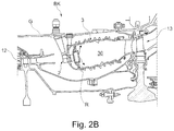
- FIG. 2B shows, in sections and on an enlarged scale, the combustion chamber of the engine of FIG. 2A ;
- FIG. 2C shows, in a cross-sectional view, the general structure of the nozzle of FIG. 1 and the surrounding components of the engine in the installed state of the nozzle.
- FIG. 2A schematically illustrates, in a sectional view, a (turbofan) engine T in which the individual engine components are arranged in succession along a rotational axis or central axis M and the engine T is embodied as a turbofan engine.
- a fan F By means of a fan F, air is suctioned in along an entry direction at an inlet or an intake E of the engine T.
- This fan F which is arranged inside a fan housing FC, is driven via a rotor shaft S that is set into rotation by a turbine TT of the engine T.
- the turbine TT connects to a compressor V, which for example has a low-pressure compressor 11 and a high-pressure compressor 12 , and where necessary also a medium-pressure compressor.
- the fan F supplies air to the compressor V in a primary air flow F 1 , on the one hand, and, on the other, to a secondary flow channel or bypass channel B in a secondary air flow F 2 for creating a thrust.
- the bypass channel B extends about a core engine that comprises the compressor V and the turbine TT, and also comprises a primary flow channel for the air that is supplied to the core engine by the fan F.
- the air that is conveyed via the compressor V into the primary flow channel is transported into the combustion chamber section BK of the core engine where the driving power for driving the turbine TT is generated.
- the turbine TT has a high-pressure turbine 13 , a medium-pressure turbine 14 , and a low-pressure turbine 15 .
- the turbine TT drives the rotor shaft S and thus the fan F by means of the energy that is released during combustion in order to generate the necessary thrust by means of the air that is conveyed into the bypass channel B.
- the air from the bypass channel B as well as the exhaust gases from the primary flow channel of the core engine are discharged via an outlet A at the end of the engine T.
- the outlet A usually has a thrust nozzle with a centrally arranged outlet cone C.
- FIG. 2B shows a longitudinal section through the combustion chamber section BK of the engine T.
- a nozzle assembly group is provided for injecting fuel or an air-fuel mixture into a combustion space 30 of the combustion chamber 3 .
- It comprises a combustion chamber ring R at which multiple (fuel/injection) nozzles 2 are arranged along a circular line about the central axis M.
- the nozzle exit openings of the respective nozzles 2 that are positioned inside the combustion chamber 3 are provided at the combustion chamber ring R.
- each nozzle 2 comprises a flange by means of which a nozzle 2 is screwed to an outer housing G of the combustion chamber 3 .
- FIG. 2C now shows a cross-sectional view of the basic structure of a nozzle 2 as well as the surrounding components of the engine T in the installed state of the nozzle 2 .
- the nozzle 2 is part of a combustion chamber system of the engine T.
- the nozzle 2 is located downstream of a diffuser D, and during mounting is inserted through an access hole L through a combustion chamber head 31 , through a heat shield 300 and a head plate 310 of the combustion chamber 3 up to the combustion space 30 of the combustion chamber 3 , so that a nozzle exit opening formed at a nozzle main body 20 reaches all the way to the combustion space 30 .
- the nozzle 2 further comprises a nozzle neck 21 which substantially extends radially with respect to the central axis M and inside of which a fuel supply 210 conveying fuel to the nozzle main body 20 is accommodated. Further formed at the nozzle main body 20 are a fuel chamber 22 , fuel passages 220 , heat shields 23 as well as air chambers for insulation.
- the nozzle main body 20 forms a (first) inner air guiding channel 26 extending centrally along a nozzle longitudinal axis DM and, positioned radially further outside with respect to the same, (second and third) outer air guiding channels 27 a and 27 b .
- These air guiding channels 26 , 27 a and 27 b extend in the direction of the nozzle exit opening of the nozzle 2 .
- At least one fuel guiding channel 25 is formed at the nozzle main body 20 .
- This fuel guiding channel 25 is located between the first inner air guiding channel 26 and the second outer air guiding channel 27 a .
- the end of the fuel guiding channel 25 via which fuel flows out in the direction of the air from the first inner air guiding channel 26 during operation of the nozzle 2 , is located with respect to the nozzle longitudinal axis DM and in the direction of the nozzle exit opening in front of the end of the second air guiding channel 27 a from which air from the second, outer air guiding channel 27 a flows out in the direction of a mixture of air from the first, inner air guiding channel 26 and fuel from the fuel guiding channel 25 .
- the nozzle main body 20 also comprises an outer, radially inwardly oriented air guiding element 41 at the end of the third outer air guiding channel 27 b .
- a sealing element 28 is also provided at the nozzle main body 20 at its circumference for sealing the nozzle 2 towards the combustion space 30 .
- This sealing element 28 forms a counter-piece to a so-called burner seal 4 .
- This burner seal 4 is floatingly mounted between the heat shield 300 and the head plate 310 to compensate for radial and axial movements between the nozzle 2 and the combustion chamber 3 and to ensure reliable sealing in different operational states.
- the burner seal 4 usually has a flow guiding element 40 towards the combustion space 30 .
- this flow guiding element 40 ensures a desired flow guidance of the fuel-air mixture that comes from the nozzle 2 , more precisely the swirled air from the air guiding channels 26 , 27 a and 27 b , as well as the fuel guiding channel 25 .
- the ends of the second and third radially outwardly located air guiding channels 27 a and 27 b follow—with respect to the nozzle longitudinal axis DM and in the direction of the nozzle exit opening—the end of the fuel guiding channel 25 from which fuel is supplied to the air from the first inner centrally extending air guiding channel 26 during operation of the engine T.
- a tapering channel portion 9 with a shell surface 292 b that extends in an inclined manner in the axial direction is formed between the end of the fuel guiding channel 25 and the end of the second air guiding channel 27 a at the nozzle 2 .
- the inclined shell surface 292 b of the channel portion 9 connects to a radially outer shell surface 291 b of the fuel guiding channel 25 .
- the shell surfaces 291 b and 292 b extend at an angle to each other that is larger than 10° so as to define, via the shell surface 292 b connecting to the fuel guiding channel 25 , a “pre-film” surface for attachment of fuel, extending in the direction of the nozzle exit opening.
- the fuel guiding channel 25 thus transitions into the channel portion 9 which tapers off in the direction of the nozzle exit opening and thus towards an end of the second radially outwardly located air guiding channel 27 a or that converges in the direction of the nozzle exit opening.
- the fuel guiding channel 25 is formed with a radially inwardly angled channel section 251 .
- This angled channel section 251 connects to a channel section 250 of the fuel guiding channel 25 that extends substantially in parallel to the nozzle longitudinal axis DM and that is bordered, corresponding to the cross-sectional view of FIG. 1A , by inner and outer shell surfaces 290 a and 290 b that extend in parallel to one another.
- the transition between the fuel guiding channel 25 and the channel portion 9 in the area of the shell surfaces 291 b and 292 b is designed to be continuous and edge-free via a curvature that has a radius R PFO , here of maximally 2 mm.
- the (consistently) larger diameter of the channel portion 9 as compared to the diameter of the inner, first air guiding channel 26 results from a radial offset of the outer shell surface 292 b of the channel portion 9 to an end of the shell surface of the first air guiding channel 26 .
- the fuel guiding channel 25 is not completely guided up to a diameter of the first air guiding channel 26 .
- the diameter of the channel portion 9 is larger than a diameter 2r inner of the first air guiding channel 26 at the end of the fuel guiding channel 25 by a distance 2 ⁇ r 1 .
- the shell surface 292 b of the channel portion 9 is offset radially outwards by a distance ⁇ r 1 to an end of the shell surface of the first air guiding channel 26 .
- the distance ⁇ r 1 is less than 0.8 mm, in particular less than 0.665 mm.
- the distance ⁇ r 1 can be at least 0.2 mm and maximally 2 mm.
- ⁇ r 1 can also be less than 0.2 mm, or even zero.
- the channel portion 9 tapers in the direction of the nozzle exit opening over a length x PF . However, an offset to the end of the first air guiding channel 26 still remains.
- the shell surface 292 b of the channel portion 9 is also radially offset in the area of the end of the second air guiding channel 27 b and thus at the (rear, downstream) end of the channel portion 9 by a distance ⁇ r 2 (with 0 ⁇ r 2 ⁇ r 1 ) to the shell surface of the first air guiding channel 26 . Accordingly, while extending radially inward, the shell surface 292 b of the channel portion 9 does not extend beyond a virtual extension of a radially outer terminal edge of the first air guiding channel 26 .
- a distance ⁇ r 2 is for example at least 0.1 mm, in particular 0.2 mm.
- the taper of the channel portion 9 is further chosen in such a manner that the shell surface 292 b of the channel portion 29 extends at an angle ⁇ 40° to the nozzle longitudinal axis DM.
- the fuel is then conveyed more evenly via the shell surface 292 b of the channel portion 9 which then serves as a guide surface for a film of fuel, which results in a homogenous fuel drop distribution in the fuel-air mixture at the nozzle exit opening.
- the length x PF can be limited to maximally 7 mm, for example. For example, x PF ⁇ 3 ⁇ r 1 applies.
- the distances ⁇ r 1 and ⁇ r 2 and the length x PF can also be chosen in a different manner, in particular depending on a predefined mass flow of fuel at certain predefined operating points of the engine T as well as the diameter 2r inner of the inner first air guiding channel 26 .
- the length in x PF should for example be so long that local non-stationary effects due to the discharge of fuel from the fuel guiding channel 25 are spatially separated from a multiphase flow at a (atomizer) edge e ll .
- This edge e ll is formed at a transition of the shell surface 292 b of the channel portion 9 and a radially inner shell surface of the second outer air guiding channel 27 a .
- the edge e ll is further designed to be as sharp as possible to avoid local back flows at the tapered end of the channel portion 9 .
- a wall section 29 b of the nozzle main body 2 which, on the one hand, forms the shell surface of the channel portion 9 and, on the other hand, forms the radially inner shell surface of the second air guiding channel 27 a , thus tapers off towards the edge e ll at the end of the channel portion 9 and of the second air guiding channel 27 a .
- a sharp-edged transition is formed between the shell surface 292 b of the channel portion 9 and the inner shell surface of the second air guiding channel 27 a.
- a sharp-edged transition is also formed between the shell surface of the first air guiding channel 26 and the inner shell surface 291 a of the fuel guiding channel 25 at the end of the fuel guiding channel 25 .
- a wall section 29 a of the nozzle main body 2 which, on the one hand, forms the inner shell surface 291 a of the fuel guiding channel 25 and, on the other hand, forms the shell surface of the first air guiding channel 26 thus also tapers off towards an edge e l at the end of the fuel guiding channel 25 and of the first air guiding channel 26 .
- the (end) edge e ll can be located radially further inside with respect to the radially inner (end-) edge e l of the fuel guiding channel 25 , so that a value for ⁇ r 2 can be “negative”, that is, r inner >r outer applies, wherein 2 r outer corresponds to the diameter of the channel portion 9 at its nozzle-exit-side end (at the edge e ll ).
- an (end) section of the fuel guiding channel 25 also connects downstream to the angled channel section 251 of the fuel guiding channel 25 extending axially in the direction of the nozzle exit opening.
- a concave curvature is provided at the radially inner shell surface 291 a of the fuel guiding channel 25 via which the angled and thus obliquely radially inwardly oriented section of the radially inner shell surface transitions into an axially extending section.
- the concave curvature has a radius R Duct of maximally 15 mm and is located opposite the convex curvature at the radially outer shell surface 291 b with the radius R PFO .
- An axial length of the axially extending, radial inwardly located end section of the fuel guiding channel 25 may for example only correspond to a fraction of the length x PF . For example, this length is smaller than 0.5 x PF .
- the radius R PFO can vary depending on the size of the curvature at the radially inner shell surface 291 a and in particular the accompanying axial length of the axially extending, radially inwardly located end section of the fuel guiding channel 25 (that is tapering towards the edge e l at the end). If an axially extending radially inwardly located end section of the fuel guiding channel 25 and a concave curvature with a radius R Duct provided for the transition are present, with 0 ⁇ R Duct ⁇ 15 mm, the radius R PFO of the convex curvature at the radially outer shell surface 291 b is maximally 8 mm.
Landscapes
- Engineering & Computer Science (AREA)
- Chemical & Material Sciences (AREA)
- Combustion & Propulsion (AREA)
- Mechanical Engineering (AREA)
- General Engineering & Computer Science (AREA)
- Fuel-Injection Apparatus (AREA)
- Spray-Type Burners (AREA)
Abstract
Description
x PF≥2 Δr 1.
- 11 low-pressure compressor
- 12 high-pressure compressor
- 13 high-pressure turbine
- 14 medium-pressure turbine
- 15 low-pressure turbine
- 2 nozzle
- 20 nozzle main body
- 21 neck
- 210 fuel supply
- 22 fuel chamber
- 220 fuel passage
- 23 heat shield
- 24 a, 24 b air chamber
- 25 fuel guiding channel
- 250, 251 channel section
- 26 first air guiding channel
- 27 a second air guiding channel
- 27 b third air guiding channel
- 28 sealing element
- 290 a, 290 b, 291 a, 291 b shell surface
- 292 b shell surface/guide surface
- 29 a, 29 b wall section
- 3 combustion chamber
- 30 combustion space
- 300 heat shield
- 31 combustion chamber head
- 310 head plate
- 4 burner seal
- 40 flow guiding element
- 41 air guiding element
- 9 channel portion
- A outlet
- B bypass channel
- BK combustion chamber section
- C outlet cone
- D diffuser
- DM nozzle longitudinal axis
- E inlet/intake
- el, ell edge
- F fan
- F1, F2 fluid flow
- FC fan housing
- G outer housing
- L access hole
- M central axis/rotational axis
- R combustion chamber ring
- RF reference axis
- rinner radius
- RDuct, RPFO radius
- S rotor shaft
- T (turbofan) engine
- TT turbine
- V compressor
- xPF length
- Δr1, Δr2 distance
- α angle
Claims (16)
Applications Claiming Priority (2)
| Application Number | Priority Date | Filing Date | Title |
|---|---|---|---|
| DE102017218529.5A DE102017218529A1 (en) | 2017-10-17 | 2017-10-17 | Nozzle for a combustion chamber of an engine |
| DE102017218529.5 | 2017-10-17 |
Publications (2)
| Publication Number | Publication Date |
|---|---|
| US20190113226A1 US20190113226A1 (en) | 2019-04-18 |
| US11085632B2 true US11085632B2 (en) | 2021-08-10 |
Family
ID=63787819
Family Applications (1)
| Application Number | Title | Priority Date | Filing Date |
|---|---|---|---|
| US16/161,871 Active 2039-04-05 US11085632B2 (en) | 2017-10-17 | 2018-10-16 | Nozzle for a combustion chamber of an engine |
Country Status (3)
| Country | Link |
|---|---|
| US (1) | US11085632B2 (en) |
| EP (1) | EP3473930B1 (en) |
| DE (1) | DE102017218529A1 (en) |
Families Citing this family (4)
| Publication number | Priority date | Publication date | Assignee | Title |
|---|---|---|---|---|
| DE102018106051A1 (en) * | 2018-03-15 | 2019-09-19 | Rolls-Royce Deutschland Ltd & Co Kg | Combustion chamber assembly with burner seal and nozzle and a Leitströmungserzeugungseinrichtung |
| CN116066855B (en) * | 2023-02-14 | 2025-05-30 | 上海慕帆动力科技有限公司 | Gas turbine combustion chamber structure with circumferentially dispersed main combustion nozzles |
| GB202405296D0 (en) | 2024-04-15 | 2024-05-29 | Rolls Royce Plc | Nozzle body for fuel injector |
| DE102024132232A1 (en) | 2024-11-05 | 2026-05-07 | Rolls-Royce Deutschland Ltd & Co Kg | Nozzle for supplying air and liquid fuel to a combustion chamber and engine |
Citations (19)
| Publication number | Priority date | Publication date | Assignee | Title |
|---|---|---|---|---|
| DE2544361A1 (en) | 1974-10-07 | 1976-04-22 | Parker Hannifin Corp | FUEL INJECTOR |
| US3980233A (en) * | 1974-10-07 | 1976-09-14 | Parker-Hannifin Corporation | Air-atomizing fuel nozzle |
| US4941617A (en) | 1988-12-14 | 1990-07-17 | United Technologies Corporation | Airblast fuel nozzle |
| US4946105A (en) * | 1988-04-12 | 1990-08-07 | United Technologies Corporation | Fuel nozzle for gas turbine engine |
| US5044559A (en) * | 1988-11-02 | 1991-09-03 | United Technologies Corporation | Gas assisted liquid atomizer |
| US20070028619A1 (en) | 2005-08-05 | 2007-02-08 | Rolls-Royce Plc | Fuel injector |
| US20090100837A1 (en) * | 2007-10-18 | 2009-04-23 | Ralf Sebastian Von Der Bank | Lean premix burner for a gas-turbine engine |
| US20090255258A1 (en) | 2008-04-11 | 2009-10-15 | Delavan Inc | Pre-filming air-blast fuel injector having a reduced hydraulic spray angle |
| US20100308135A1 (en) | 2009-06-03 | 2010-12-09 | Japan Aerospace Exploration Agency | Staging fuel nozzle |
| US20140174096A1 (en) * | 2010-09-22 | 2014-06-26 | Vladimir Dusan Milosavljevic | Method and arrangement for injecting an emulsion into a flame |
| US20140241871A1 (en) * | 2013-02-27 | 2014-08-28 | Rolls-Royce Plc | Vane structure and a method of manufacturing a vane structure |
| US20160084503A1 (en) | 2014-09-24 | 2016-03-24 | Pratt & Whitney Canada Corp. | Fuel nozzle |
| US20160097537A1 (en) * | 2014-10-03 | 2016-04-07 | Pratt & Whitney Canada Corp. | Fuel nozzle |
| US20160097536A1 (en) * | 2014-10-03 | 2016-04-07 | Pratt & Whitney Canada Corp. | Fuel nozzle |
| US9423137B2 (en) | 2011-12-29 | 2016-08-23 | Rolls-Royce Corporation | Fuel injector with first and second converging fuel-air passages |
| US20170082288A1 (en) | 2015-09-18 | 2017-03-23 | Delavan Inc | Air entrance effect |
| US20170268782A1 (en) | 2016-03-15 | 2017-09-21 | Rolls-Royce Plc | Combustion chamber system and a method of operating a combustion chamber system |
| US9927126B2 (en) | 2015-06-10 | 2018-03-27 | General Electric Company | Prefilming air blast (PAB) pilot for low emissions combustors |
| US10295186B2 (en) * | 2014-03-28 | 2019-05-21 | Delavan Inc. Of Des Moines Ia | Airblast nozzle with upstream fuel distribution and near-exit swirl |
-
2017
- 2017-10-17 DE DE102017218529.5A patent/DE102017218529A1/en not_active Withdrawn
-
2018
- 2018-10-05 EP EP18198872.6A patent/EP3473930B1/en active Active
- 2018-10-16 US US16/161,871 patent/US11085632B2/en active Active
Patent Citations (22)
| Publication number | Priority date | Publication date | Assignee | Title |
|---|---|---|---|---|
| DE2544361A1 (en) | 1974-10-07 | 1976-04-22 | Parker Hannifin Corp | FUEL INJECTOR |
| US3980233A (en) * | 1974-10-07 | 1976-09-14 | Parker-Hannifin Corporation | Air-atomizing fuel nozzle |
| GB1491383A (en) | 1974-10-07 | 1977-11-09 | Parker Hannifin Corp | Air-atomising fuel nozzle |
| US4946105A (en) * | 1988-04-12 | 1990-08-07 | United Technologies Corporation | Fuel nozzle for gas turbine engine |
| US5044559A (en) * | 1988-11-02 | 1991-09-03 | United Technologies Corporation | Gas assisted liquid atomizer |
| US4941617A (en) | 1988-12-14 | 1990-07-17 | United Technologies Corporation | Airblast fuel nozzle |
| US20070028619A1 (en) | 2005-08-05 | 2007-02-08 | Rolls-Royce Plc | Fuel injector |
| US20090100837A1 (en) * | 2007-10-18 | 2009-04-23 | Ralf Sebastian Von Der Bank | Lean premix burner for a gas-turbine engine |
| US20090255258A1 (en) | 2008-04-11 | 2009-10-15 | Delavan Inc | Pre-filming air-blast fuel injector having a reduced hydraulic spray angle |
| DE102009017056A1 (en) | 2008-04-11 | 2009-10-15 | Delavan Inc | Pre-film laying airflow fuel injector having a reduced hydraulic spray angle |
| US20100308135A1 (en) | 2009-06-03 | 2010-12-09 | Japan Aerospace Exploration Agency | Staging fuel nozzle |
| US20140174096A1 (en) * | 2010-09-22 | 2014-06-26 | Vladimir Dusan Milosavljevic | Method and arrangement for injecting an emulsion into a flame |
| US20140338353A1 (en) | 2010-09-22 | 2014-11-20 | Siemens Aktiengesellschaft | Method and arrangement for injecting an emulsion into a flame |
| US9423137B2 (en) | 2011-12-29 | 2016-08-23 | Rolls-Royce Corporation | Fuel injector with first and second converging fuel-air passages |
| US20140241871A1 (en) * | 2013-02-27 | 2014-08-28 | Rolls-Royce Plc | Vane structure and a method of manufacturing a vane structure |
| US10295186B2 (en) * | 2014-03-28 | 2019-05-21 | Delavan Inc. Of Des Moines Ia | Airblast nozzle with upstream fuel distribution and near-exit swirl |
| US20160084503A1 (en) | 2014-09-24 | 2016-03-24 | Pratt & Whitney Canada Corp. | Fuel nozzle |
| US20160097537A1 (en) * | 2014-10-03 | 2016-04-07 | Pratt & Whitney Canada Corp. | Fuel nozzle |
| US20160097536A1 (en) * | 2014-10-03 | 2016-04-07 | Pratt & Whitney Canada Corp. | Fuel nozzle |
| US9927126B2 (en) | 2015-06-10 | 2018-03-27 | General Electric Company | Prefilming air blast (PAB) pilot for low emissions combustors |
| US20170082288A1 (en) | 2015-09-18 | 2017-03-23 | Delavan Inc | Air entrance effect |
| US20170268782A1 (en) | 2016-03-15 | 2017-09-21 | Rolls-Royce Plc | Combustion chamber system and a method of operating a combustion chamber system |
Non-Patent Citations (2)
| Title |
|---|
| European Search Report dated Feb. 25, 2019 for counterpart European Patent Application No. 18198872.6. |
| German Search Report dated Jun. 13, 2018 for counterpart German Patent Application No. 10 2017 218 529.5. |
Also Published As
| Publication number | Publication date |
|---|---|
| EP3473930B1 (en) | 2024-01-24 |
| DE102017218529A1 (en) | 2019-04-18 |
| US20190113226A1 (en) | 2019-04-18 |
| EP3473930A1 (en) | 2019-04-24 |
Similar Documents
| Publication | Publication Date | Title |
|---|---|---|
| US10808935B2 (en) | Fuel spray nozzle comprising axially projecting air guiding element for a combustion chamber of a gas turbine engine | |
| US4891936A (en) | Turbine combustor with tangential fuel injection and bender jets | |
| EP4008959B1 (en) | Apparatus for a turbine engine including a fuel splash plate | |
| US11085632B2 (en) | Nozzle for a combustion chamber of an engine | |
| US6871488B2 (en) | Natural gas fuel nozzle for gas turbine engine | |
| US9512733B2 (en) | Diffuser/rectifier assembly for a turbine engine with corrugated downstream walls | |
| US10883719B2 (en) | Prefilming fuel/air mixer | |
| US8555649B2 (en) | Fuel nozzle swirler assembly | |
| US10047959B2 (en) | Fuel injector for fuel spray nozzle | |
| US10914237B2 (en) | Airblast injector for a gas turbine engine | |
| US11885497B2 (en) | Fuel nozzle with slot for cooling | |
| US20220082259A1 (en) | Injection system for turbomachine, comprising a swirler and mixing bowl vortex holes | |
| US12584631B2 (en) | Nozzle assembly with a central fuel pipe that is sealed against an in-flow of air | |
| US9127841B2 (en) | Turbomachine combustion chamber comprising improved means of air supply | |
| US20190093896A1 (en) | Nozzle comprising axial extension for a combustion chamber of an engine | |
| CN112005051B (en) | Injection system for an annular combustion chamber of a turbine engine | |
| US10808623B2 (en) | Combustion chamber assembly with burner seal and nozzle as well as guiding flow generating equipment | |
| US20100024425A1 (en) | Turbine engine fuel nozzle | |
| US20210285640A1 (en) | Nozzle with jet generator channel for fuel to be injected into a combustion chamber of an engine | |
| US9546600B2 (en) | Nozzle having an orifice plug for a gas turbomachine | |
| CN109073224B (en) | Intake swirler including pneumatic deflector at inlet for turbine injection system | |
| EP3376111B1 (en) | Combustor cowl | |
| US9689571B2 (en) | Offset stem fuel distributor | |
| US12339004B2 (en) | Nozzle assembly with nozzle head having guide element | |
| US8893502B2 (en) | Augmentor spray bar with tip support bushing |
Legal Events
| Date | Code | Title | Description |
|---|---|---|---|
| AS | Assignment |
Owner name: ROLLS-ROYCE DEUTSCHLAND LTD & CO KG, GERMANY Free format text: ASSIGNMENT OF ASSIGNORS INTEREST;ASSIGNORS:DAUCH, THILO;KOCH, RAINER;BAUER, HANS-JORG;AND OTHERS;SIGNING DATES FROM 20171026 TO 20171027;REEL/FRAME:047184/0293 |
|
| FEPP | Fee payment procedure |
Free format text: ENTITY STATUS SET TO UNDISCOUNTED (ORIGINAL EVENT CODE: BIG.); ENTITY STATUS OF PATENT OWNER: LARGE ENTITY |
|
| STPP | Information on status: patent application and granting procedure in general |
Free format text: DOCKETED NEW CASE - READY FOR EXAMINATION |
|
| STPP | Information on status: patent application and granting procedure in general |
Free format text: NON FINAL ACTION MAILED |
|
| STPP | Information on status: patent application and granting procedure in general |
Free format text: FINAL REJECTION MAILED |
|
| STPP | Information on status: patent application and granting procedure in general |
Free format text: RESPONSE AFTER FINAL ACTION FORWARDED TO EXAMINER |
|
| STPP | Information on status: patent application and granting procedure in general |
Free format text: NOTICE OF ALLOWANCE MAILED -- APPLICATION RECEIVED IN OFFICE OF PUBLICATIONS |
|
| STPP | Information on status: patent application and granting procedure in general |
Free format text: AWAITING TC RESP., ISSUE FEE NOT PAID |
|
| STPP | Information on status: patent application and granting procedure in general |
Free format text: AWAITING TC RESP, ISSUE FEE PAYMENT VERIFIED |
|
| STPP | Information on status: patent application and granting procedure in general |
Free format text: PUBLICATIONS -- ISSUE FEE PAYMENT VERIFIED |
|
| STCF | Information on status: patent grant |
Free format text: PATENTED CASE |
|
| MAFP | Maintenance fee payment |
Free format text: PAYMENT OF MAINTENANCE FEE, 4TH YEAR, LARGE ENTITY (ORIGINAL EVENT CODE: M1551); ENTITY STATUS OF PATENT OWNER: LARGE ENTITY Year of fee payment: 4 |