US11084151B1 - Siding straightening tool and method of use - Google Patents
Siding straightening tool and method of use Download PDFInfo
- Publication number
- US11084151B1 US11084151B1 US16/415,156 US201916415156A US11084151B1 US 11084151 B1 US11084151 B1 US 11084151B1 US 201916415156 A US201916415156 A US 201916415156A US 11084151 B1 US11084151 B1 US 11084151B1
- Authority
- US
- United States
- Prior art keywords
- siding
- arms
- mold
- tool
- ratchets
- Prior art date
- Legal status (The legal status is an assumption and is not a legal conclusion. Google has not performed a legal analysis and makes no representation as to the accuracy of the status listed.)
- Expired - Fee Related, expires
Links
Images


Classifications
-
- B—PERFORMING OPERATIONS; TRANSPORTING
- B25—HAND TOOLS; PORTABLE POWER-DRIVEN TOOLS; MANIPULATORS
- B25B—TOOLS OR BENCH DEVICES NOT OTHERWISE PROVIDED FOR, FOR FASTENING, CONNECTING, DISENGAGING OR HOLDING
- B25B27/00—Hand tools, specially adapted for fitting together or separating parts or objects whether or not involving some deformation, not otherwise provided for
- B25B27/02—Hand tools, specially adapted for fitting together or separating parts or objects whether or not involving some deformation, not otherwise provided for for connecting objects by press fit or detaching same
-
- E—FIXED CONSTRUCTIONS
- E04—BUILDING
- E04F—FINISHING WORK ON BUILDINGS, e.g. STAIRS, FLOORS
- E04F21/00—Implements for finishing work on buildings
- E04F21/18—Implements for finishing work on buildings for setting wall or ceiling slabs or plates
- E04F21/1838—Implements for finishing work on buildings for setting wall or ceiling slabs or plates for setting a plurality of similar elements
- E04F21/1844—Implements for finishing work on buildings for setting wall or ceiling slabs or plates for setting a plurality of similar elements by applying them one by one
- E04F21/1855—Implements for finishing work on buildings for setting wall or ceiling slabs or plates for setting a plurality of similar elements by applying them one by one of elongated elements, e.g. sidings
-
- B—PERFORMING OPERATIONS; TRANSPORTING
- B25—HAND TOOLS; PORTABLE POWER-DRIVEN TOOLS; MANIPULATORS
- B25B—TOOLS OR BENCH DEVICES NOT OTHERWISE PROVIDED FOR, FOR FASTENING, CONNECTING, DISENGAGING OR HOLDING
- B25B13/00—Spanners; Wrenches
- B25B13/10—Spanners; Wrenches with adjustable jaws
- B25B13/12—Spanners; Wrenches with adjustable jaws the jaws being slidable
- B25B13/20—Arrangements for locking the jaws
- B25B13/22—Arrangements for locking the jaws by ratchet action or toothed bars
-
- B—PERFORMING OPERATIONS; TRANSPORTING
- B25—HAND TOOLS; PORTABLE POWER-DRIVEN TOOLS; MANIPULATORS
- B25B—TOOLS OR BENCH DEVICES NOT OTHERWISE PROVIDED FOR, FOR FASTENING, CONNECTING, DISENGAGING OR HOLDING
- B25B5/00—Clamps
- B25B5/04—Clamps with pivoted jaws
-
- B—PERFORMING OPERATIONS; TRANSPORTING
- B25—HAND TOOLS; PORTABLE POWER-DRIVEN TOOLS; MANIPULATORS
- B25B—TOOLS OR BENCH DEVICES NOT OTHERWISE PROVIDED FOR, FOR FASTENING, CONNECTING, DISENGAGING OR HOLDING
- B25B5/00—Clamps
- B25B5/06—Arrangements for positively actuating jaws
-
- B—PERFORMING OPERATIONS; TRANSPORTING
- B25—HAND TOOLS; PORTABLE POWER-DRIVEN TOOLS; MANIPULATORS
- B25B—TOOLS OR BENCH DEVICES NOT OTHERWISE PROVIDED FOR, FOR FASTENING, CONNECTING, DISENGAGING OR HOLDING
- B25B5/00—Clamps
- B25B5/16—Details, e.g. jaws, jaw attachments
- B25B5/163—Jaws or jaw attachments
-
- B—PERFORMING OPERATIONS; TRANSPORTING
- B29—WORKING OF PLASTICS; WORKING OF SUBSTANCES IN A PLASTIC STATE IN GENERAL
- B29C—SHAPING OR JOINING OF PLASTICS; SHAPING OF MATERIAL IN A PLASTIC STATE, NOT OTHERWISE PROVIDED FOR; AFTER-TREATMENT OF THE SHAPED PRODUCTS, e.g. REPAIRING
- B29C53/00—Shaping by bending, folding, twisting, straightening or flattening; Apparatus therefor
-
- E04B1/54—
-
- E—FIXED CONSTRUCTIONS
- E04—BUILDING
- E04B—GENERAL BUILDING CONSTRUCTIONS; WALLS, e.g. PARTITIONS; ROOFS; FLOORS; CEILINGS; INSULATION OR OTHER PROTECTION OF BUILDINGS
- E04B1/00—Constructions in general; Structures which are not restricted either to walls, e.g. partitions, or floors or ceilings or roofs
- E04B1/38—Connections for building structures in general
- E04B1/541—Joints substantially without separate connecting elements, e.g. jointing by inter-engagement
-
- E—FIXED CONSTRUCTIONS
- E04—BUILDING
- E04C—STRUCTURAL ELEMENTS; BUILDING MATERIALS
- E04C2/00—Building elements of relatively thin form for the construction of parts of buildings, e.g. sheet materials, slabs, or panels
- E04C2/30—Building elements of relatively thin form for the construction of parts of buildings, e.g. sheet materials, slabs, or panels characterised by the shape or structure
- E04C2/38—Building elements of relatively thin form for the construction of parts of buildings, e.g. sheet materials, slabs, or panels characterised by the shape or structure with attached ribs, flanges, or the like, e.g. framed panels
-
- E—FIXED CONSTRUCTIONS
- E04—BUILDING
- E04F—FINISHING WORK ON BUILDINGS, e.g. STAIRS, FLOORS
- E04F13/00—Coverings or linings, e.g. for walls or ceilings
- E04F13/07—Coverings or linings, e.g. for walls or ceilings composed of covering or lining elements; Sub-structures therefor; Fastening means therefor
- E04F13/08—Coverings or linings, e.g. for walls or ceilings composed of covering or lining elements; Sub-structures therefor; Fastening means therefor composed of a plurality of similar covering or lining elements
- E04F13/0862—Coverings or linings, e.g. for walls or ceilings composed of covering or lining elements; Sub-structures therefor; Fastening means therefor composed of a plurality of similar covering or lining elements composed of a number of elements which are identical or not, e.g. carried by a common web, support plate or grid
-
- E—FIXED CONSTRUCTIONS
- E04—BUILDING
- E04F—FINISHING WORK ON BUILDINGS, e.g. STAIRS, FLOORS
- E04F13/00—Coverings or linings, e.g. for walls or ceilings
- E04F13/07—Coverings or linings, e.g. for walls or ceilings composed of covering or lining elements; Sub-structures therefor; Fastening means therefor
- E04F13/08—Coverings or linings, e.g. for walls or ceilings composed of covering or lining elements; Sub-structures therefor; Fastening means therefor composed of a plurality of similar covering or lining elements
- E04F13/0889—Coverings or linings, e.g. for walls or ceilings composed of covering or lining elements; Sub-structures therefor; Fastening means therefor composed of a plurality of similar covering or lining elements characterised by the joints between neighbouring elements, e.g. with joint fillings or with tongue and groove connections
- E04F13/0894—Coverings or linings, e.g. for walls or ceilings composed of covering or lining elements; Sub-structures therefor; Fastening means therefor composed of a plurality of similar covering or lining elements characterised by the joints between neighbouring elements, e.g. with joint fillings or with tongue and groove connections with tongue and groove connections
-
- E—FIXED CONSTRUCTIONS
- E04—BUILDING
- E04F—FINISHING WORK ON BUILDINGS, e.g. STAIRS, FLOORS
- E04F2201/00—Joining sheets or plates or panels
-
- E—FIXED CONSTRUCTIONS
- E04—BUILDING
- E04F—FINISHING WORK ON BUILDINGS, e.g. STAIRS, FLOORS
- E04F2201/00—Joining sheets or plates or panels
- E04F2201/03—Undercut connections, e.g. using undercut tongues or grooves
-
- F—MECHANICAL ENGINEERING; LIGHTING; HEATING; WEAPONS; BLASTING
- F16—ENGINEERING ELEMENTS AND UNITS; GENERAL MEASURES FOR PRODUCING AND MAINTAINING EFFECTIVE FUNCTIONING OF MACHINES OR INSTALLATIONS; THERMAL INSULATION IN GENERAL
- F16B—DEVICES FOR FASTENING OR SECURING CONSTRUCTIONAL ELEMENTS OR MACHINE PARTS TOGETHER, e.g. NAILS, BOLTS, CIRCLIPS, CLAMPS, CLIPS OR WEDGES; JOINTS OR JOINTING
- F16B2/00—Friction-grip releasable fastenings
- F16B2/02—Clamps, i.e. with gripping action effected by positive means other than the inherent resistance to deformation of the material of the fastening
- F16B2/06—Clamps, i.e. with gripping action effected by positive means other than the inherent resistance to deformation of the material of the fastening external, i.e. with contracting action
- F16B2/10—Clamps, i.e. with gripping action effected by positive means other than the inherent resistance to deformation of the material of the fastening external, i.e. with contracting action using pivoting jaws
-
- Y—GENERAL TAGGING OF NEW TECHNOLOGICAL DEVELOPMENTS; GENERAL TAGGING OF CROSS-SECTIONAL TECHNOLOGIES SPANNING OVER SEVERAL SECTIONS OF THE IPC; TECHNICAL SUBJECTS COVERED BY FORMER USPC CROSS-REFERENCE ART COLLECTIONS [XRACs] AND DIGESTS
- Y10—TECHNICAL SUBJECTS COVERED BY FORMER USPC
- Y10T—TECHNICAL SUBJECTS COVERED BY FORMER US CLASSIFICATION
- Y10T29/00—Metal working
- Y10T29/53—Means to assemble or disassemble
- Y10T29/53909—Means comprising hand manipulatable tool
- Y10T29/53943—Hand gripper for direct push or pull
Definitions
- the present invention relates generally to siding installation systems such as for houses, and more specifically, to a siding straightening tool for straightening bowing of a piece of siding prior to installation.
- FIG. 1 depicts a conventional siding installation system 101 having a wall 103 configured to receive one or more pieces of siding 105 thereon, the siding having tongue and groove 107 pieces to engage with one another. The siding is secured in place via nails 109 or the like.
- FIG. 1 is a side view of conventional siding installation
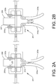
- FIGS. 2A and 2B are top views of a siding installation tool common in accordance with a preferred embodiment of the present application.
- FIGS. 3A and 3B are side views of the tool of FIGS. 2A and 2B ;
- FIG. 4 is a flowchart of the method of use of the tool of FIGS. 2A and 2B .
- the system and method of use in accordance with the present application overcomes one or more of the above-discussed problems commonly associated with conventional siding installation. Specifically, the present invention provides a tool that aids in straightening siding prior to installation.
- FIGS. 2A and 2B depict top views of a siding installation tool 201 in accordance with a preferred embodiment of the present application. It will be appreciated that tool 201 overcomes one or more of the above-listed problems commonly associated with conventional siding installation.
- tool 201 includes two arms 203 a - b , extending away from ratchets 205 a - b , and further configured to open and close one or more spikes 207 .
- the arms are configured to open and close the spikes, thereby engaging and disengaging the spikes 207 with a structure 209 , such as a 2 x 4 .
- a structure 209 such as a 2 x 4 .
- the tool is held in place above a piece of siding 211 .
- one or more buttons or releases 213 are engaged with arms 203 a - b , to release the arms, thereby releasing the spikes from the structure.
- the tool is engaged with the structure 209 via the spikes (not shown in FIGS. 3A and 3B ).
- the arms 203 a - b are pushed downward, wherein a mold 301 engages with a tongue 303 of siding 211 .
- the mold 301 is attached to the arms, thereby providing a means for the user to exert force onto the mold 301 and onto the siding, thereby straightening out the siding.
- the mold 301 can have a groove 305 , which can vary in shape and size to fit various styles of siding.
- arms 203 a - b can further include handles 307 .
- FIG. 4 a flowchart 401 is shown for further clarification of the method of use of tool 201 .
- the tool is clamped onto the structure, as shown with box 403 .
- the arms are pushed downward, wherein they pivot relative to the ratchets, as shown with box 405 .
- the mold thereby engages with the siding to straighten out the siding, as shown with box 407 .
- the user can then secure the siding in place and then release the tool, as shown with boxes 409 , 411 .
- the tool being configured to clamp onto a structure and having a mold ratcheted down to straighten out the siding. It should be appreciated that the tool can be used for exterior siding, interior siding, ceiling siding, or any other application in which siding is used.
Landscapes
- Engineering & Computer Science (AREA)
- Architecture (AREA)
- Mechanical Engineering (AREA)
- Civil Engineering (AREA)
- Structural Engineering (AREA)
- Physics & Mathematics (AREA)
- Electromagnetism (AREA)
- Finishing Walls (AREA)
Abstract
-
- one or more spikes extending from the one or more ratchets; a release engaged with one of the two arms and to allow the arms to release; and a mold extending from the one or more arms, the mold having a groove; the two arms clamp together, thereby bringing the spikes toward each other; the mold is ratcheted down to straighten a piece of siding; and the two arms pivots via the one or more ratchets thereby engaging the mold and disengaging the mold with the siding.
Description
Claims (2)
Priority Applications (1)
| Application Number | Priority Date | Filing Date | Title |
|---|---|---|---|
| US16/415,156 US11084151B1 (en) | 2018-05-17 | 2019-05-17 | Siding straightening tool and method of use |
Applications Claiming Priority (2)
| Application Number | Priority Date | Filing Date | Title |
|---|---|---|---|
| US201862672863P | 2018-05-17 | 2018-05-17 | |
| US16/415,156 US11084151B1 (en) | 2018-05-17 | 2019-05-17 | Siding straightening tool and method of use |
Publications (1)
| Publication Number | Publication Date |
|---|---|
| US11084151B1 true US11084151B1 (en) | 2021-08-10 |
Family
ID=77178993
Family Applications (1)
| Application Number | Title | Priority Date | Filing Date |
|---|---|---|---|
| US16/415,156 Expired - Fee Related US11084151B1 (en) | 2018-05-17 | 2019-05-17 | Siding straightening tool and method of use |
Country Status (1)
| Country | Link |
|---|---|
| US (1) | US11084151B1 (en) |
Citations (4)
| Publication number | Priority date | Publication date | Assignee | Title |
|---|---|---|---|---|
| US2111106A (en) * | 1937-07-31 | 1938-03-15 | Albert H Tinnerman | Tool |
| US3049336A (en) * | 1958-02-03 | 1962-08-14 | John D Proffit | Carpenter's tool |
| US8454070B2 (en) * | 2011-05-17 | 2013-06-04 | Karl-Heinz Bierfreund | Gripper for pulling arrows |
| US20170051871A1 (en) * | 2015-08-23 | 2017-02-23 | Cara J. Brzezicki | Object securing device |
-
2019
- 2019-05-17 US US16/415,156 patent/US11084151B1/en not_active Expired - Fee Related
Patent Citations (4)
| Publication number | Priority date | Publication date | Assignee | Title |
|---|---|---|---|---|
| US2111106A (en) * | 1937-07-31 | 1938-03-15 | Albert H Tinnerman | Tool |
| US3049336A (en) * | 1958-02-03 | 1962-08-14 | John D Proffit | Carpenter's tool |
| US8454070B2 (en) * | 2011-05-17 | 2013-06-04 | Karl-Heinz Bierfreund | Gripper for pulling arrows |
| US20170051871A1 (en) * | 2015-08-23 | 2017-02-23 | Cara J. Brzezicki | Object securing device |
Similar Documents
| Publication | Publication Date | Title |
|---|---|---|
| USD878915S1 (en) | Stopper | |
| US9989082B2 (en) | Washer and combination washer and fastener system for building construction | |
| US4698942A (en) | Clip for holding and spacing siding panels | |
| EP1060662B1 (en) | Ear tag with tissue sample security feature | |
| USD930983S1 (en) | Case for hairstyling apparatus | |
| USD961119S1 (en) | Shingle | |
| US20070210230A1 (en) | Suspension plate for fixing to ceiling | |
| CN110462147B (en) | Assembly and method for aligning and leveling tiles | |
| US9352453B2 (en) | Multiple-function hand tool | |
| US7185879B1 (en) | Pry bar | |
| US11679704B1 (en) | Device and method for setting or removing seat trim | |
| US8833747B2 (en) | Holder for framing members and method of use | |
| US6935628B1 (en) | Clamp jaw | |
| US20070068115A1 (en) | Siding tool | |
| US11084151B1 (en) | Siding straightening tool and method of use | |
| US3023444A (en) | Trowels | |
| US9765529B2 (en) | Panel fastener | |
| US7681324B2 (en) | Prefabricated jig to position and align roof trusses | |
| CN108884681A (en) | Elastic fixing element and skirting board fixing system including it and skirting board | |
| WO2005120778A3 (en) | Combination tool | |
| CA2049566A1 (en) | Wire nail, strip of collated wire nails, and related apparatus | |
| US20150240541A1 (en) | Dual Profile Doorstop Device | |
| EP1367741A3 (en) | Method of using pilots in radio system | |
| US10837211B2 (en) | Slip resistant glass hinge system | |
| WO2005091209A3 (en) | Pressure map based fingerprint authentication method and system |
Legal Events
| Date | Code | Title | Description |
|---|---|---|---|
| FEPP | Fee payment procedure |
Free format text: ENTITY STATUS SET TO UNDISCOUNTED (ORIGINAL EVENT CODE: BIG.); ENTITY STATUS OF PATENT OWNER: MICROENTITY |
|
| FEPP | Fee payment procedure |
Free format text: ENTITY STATUS SET TO MICRO (ORIGINAL EVENT CODE: MICR); ENTITY STATUS OF PATENT OWNER: MICROENTITY |
|
| STCF | Information on status: patent grant |
Free format text: PATENTED CASE |
|
| FEPP | Fee payment procedure |
Free format text: MAINTENANCE FEE REMINDER MAILED (ORIGINAL EVENT CODE: REM.); ENTITY STATUS OF PATENT OWNER: MICROENTITY |
|
| LAPS | Lapse for failure to pay maintenance fees |
Free format text: PATENT EXPIRED FOR FAILURE TO PAY MAINTENANCE FEES (ORIGINAL EVENT CODE: EXP.); ENTITY STATUS OF PATENT OWNER: MICROENTITY |
|
| STCH | Information on status: patent discontinuation |
Free format text: PATENT EXPIRED DUE TO NONPAYMENT OF MAINTENANCE FEES UNDER 37 CFR 1.362 |
|
| FP | Lapsed due to failure to pay maintenance fee |
Effective date: 20250810 |