US11083393B2 - Non-contact tomographic imaging and thin film sensors for sensing permittivity changes - Google Patents
Non-contact tomographic imaging and thin film sensors for sensing permittivity changes Download PDFInfo
- Publication number
- US11083393B2 US11083393B2 US15/890,087 US201815890087A US11083393B2 US 11083393 B2 US11083393 B2 US 11083393B2 US 201815890087 A US201815890087 A US 201815890087A US 11083393 B2 US11083393 B2 US 11083393B2
- Authority
- US
- United States
- Prior art keywords
- interest
- stress
- region
- ect
- prosthesis
- Prior art date
- Legal status (The legal status is an assumption and is not a legal conclusion. Google has not performed a legal analysis and makes no representation as to the accuracy of the status listed.)
- Active, expires
Links
- 239000010409 thin film Substances 0.000 title description 52
- 238000003384 imaging method Methods 0.000 title description 19
- 238000012544 monitoring process Methods 0.000 claims abstract description 18
- 238000003325 tomography Methods 0.000 claims abstract description 7
- 239000004816 latex Substances 0.000 claims description 23
- 229920000126 latex Polymers 0.000 claims description 23
- 229920000767 polyaniline Polymers 0.000 claims description 18
- 230000005684 electric field Effects 0.000 claims description 13
- 239000002048 multi walled nanotube Substances 0.000 claims description 13
- CSCPPACGZOOCGX-UHFFFAOYSA-N Acetone Chemical compound CC(C)=O CSCPPACGZOOCGX-UHFFFAOYSA-N 0.000 claims description 10
- 229920000775 emeraldine polymer Polymers 0.000 claims description 3
- XLYOFNOQVPJJNP-UHFFFAOYSA-N water Chemical compound O XLYOFNOQVPJJNP-UHFFFAOYSA-N 0.000 claims description 3
- MAGFQRLKWCCTQJ-UHFFFAOYSA-M 4-ethenylbenzenesulfonate Chemical compound [O-]S(=O)(=O)C1=CC=C(C=C)C=C1 MAGFQRLKWCCTQJ-UHFFFAOYSA-M 0.000 claims 1
- 239000008367 deionised water Substances 0.000 claims 1
- 229910021641 deionized water Inorganic materials 0.000 claims 1
- 239000000463 material Substances 0.000 abstract description 60
- 238000000034 method Methods 0.000 abstract description 32
- 230000008859 change Effects 0.000 abstract description 21
- 239000010408 film Substances 0.000 description 28
- 239000000243 solution Substances 0.000 description 27
- 238000005259 measurement Methods 0.000 description 25
- 238000005516 engineering process Methods 0.000 description 24
- 238000009826 distribution Methods 0.000 description 22
- 238000012360 testing method Methods 0.000 description 19
- 239000002114 nanocomposite Substances 0.000 description 17
- 239000003990 capacitor Substances 0.000 description 15
- 230000008569 process Effects 0.000 description 14
- 210000000988 bone and bone Anatomy 0.000 description 13
- 230000005284 excitation Effects 0.000 description 11
- 229920000139 polyethylene terephthalate Polymers 0.000 description 11
- 239000005020 polyethylene terephthalate Substances 0.000 description 11
- 208000015181 infectious disease Diseases 0.000 description 10
- 229920003023 plastic Polymers 0.000 description 10
- 239000004033 plastic Substances 0.000 description 10
- 238000010586 diagram Methods 0.000 description 9
- 230000000670 limiting effect Effects 0.000 description 9
- 210000003414 extremity Anatomy 0.000 description 8
- 230000004044 response Effects 0.000 description 8
- 229920001464 poly(sodium 4-styrenesulfonate) Polymers 0.000 description 7
- 239000007921 spray Substances 0.000 description 7
- 238000010348 incorporation Methods 0.000 description 6
- 230000035945 sensitivity Effects 0.000 description 6
- 238000004519 manufacturing process Methods 0.000 description 5
- -1 poly(sodium 4-styrenesulfonate) Polymers 0.000 description 5
- 210000001519 tissue Anatomy 0.000 description 5
- 210000000689 upper leg Anatomy 0.000 description 5
- 230000001965 increasing effect Effects 0.000 description 4
- 229920001467 poly(styrenesulfonates) Polymers 0.000 description 4
- 238000002525 ultrasonication Methods 0.000 description 4
- OKTJSMMVPCPJKN-UHFFFAOYSA-N Carbon Chemical compound [C] OKTJSMMVPCPJKN-UHFFFAOYSA-N 0.000 description 3
- 229920008580 Kynar Aquatec® Polymers 0.000 description 3
- XOJVVFBFDXDTEG-UHFFFAOYSA-N Norphytane Natural products CC(C)CCCC(C)CCCC(C)CCCC(C)C XOJVVFBFDXDTEG-UHFFFAOYSA-N 0.000 description 3
- XAGFODPZIPBFFR-UHFFFAOYSA-N aluminium Chemical compound [Al] XAGFODPZIPBFFR-UHFFFAOYSA-N 0.000 description 3
- 229910052782 aluminium Inorganic materials 0.000 description 3
- 239000007853 buffer solution Substances 0.000 description 3
- 239000002041 carbon nanotube Substances 0.000 description 3
- 229910021393 carbon nanotube Inorganic materials 0.000 description 3
- 238000000151 deposition Methods 0.000 description 3
- 239000003973 paint Substances 0.000 description 3
- RYGMFSIKBFXOCR-UHFFFAOYSA-N Copper Chemical compound [Cu] RYGMFSIKBFXOCR-UHFFFAOYSA-N 0.000 description 2
- VEXZGXHMUGYJMC-UHFFFAOYSA-N Hydrochloric acid Chemical compound Cl VEXZGXHMUGYJMC-UHFFFAOYSA-N 0.000 description 2
- 238000005452 bending Methods 0.000 description 2
- 150000001875 compounds Chemical class 0.000 description 2
- 238000002591 computed tomography Methods 0.000 description 2
- 229910052802 copper Inorganic materials 0.000 description 2
- 239000010949 copper Substances 0.000 description 2
- 230000008021 deposition Effects 0.000 description 2
- 238000001514 detection method Methods 0.000 description 2
- 239000011521 glass Substances 0.000 description 2
- 238000002595 magnetic resonance imaging Methods 0.000 description 2
- 230000000873 masking effect Effects 0.000 description 2
- 238000012986 modification Methods 0.000 description 2
- 230000004048 modification Effects 0.000 description 2
- 230000036961 partial effect Effects 0.000 description 2
- 229920000915 polyvinyl chloride Polymers 0.000 description 2
- 239000004800 polyvinyl chloride Substances 0.000 description 2
- 230000002829 reductive effect Effects 0.000 description 2
- 238000011160 research Methods 0.000 description 2
- 238000005507 spraying Methods 0.000 description 2
- 238000001356 surgical procedure Methods 0.000 description 2
- 206010060968 Arthritis infective Diseases 0.000 description 1
- 239000004593 Epoxy Substances 0.000 description 1
- 235000019687 Lamb Nutrition 0.000 description 1
- 208000037099 Prosthesis Failure Diseases 0.000 description 1
- 239000000654 additive Substances 0.000 description 1
- 239000000853 adhesive Substances 0.000 description 1
- 230000001070 adhesive effect Effects 0.000 description 1
- 230000004075 alteration Effects 0.000 description 1
- 238000002266 amputation Methods 0.000 description 1
- 230000008901 benefit Effects 0.000 description 1
- 239000011230 binding agent Substances 0.000 description 1
- 230000007177 brain activity Effects 0.000 description 1
- 238000004364 calculation method Methods 0.000 description 1
- 238000012512 characterization method Methods 0.000 description 1
- 238000006243 chemical reaction Methods 0.000 description 1
- 239000002131 composite material Substances 0.000 description 1
- 238000007906 compression Methods 0.000 description 1
- 230000006835 compression Effects 0.000 description 1
- 238000013170 computed tomography imaging Methods 0.000 description 1
- 239000000470 constituent Substances 0.000 description 1
- 239000002872 contrast media Substances 0.000 description 1
- 230000008878 coupling Effects 0.000 description 1
- 238000010168 coupling process Methods 0.000 description 1
- 238000005859 coupling reaction Methods 0.000 description 1
- 238000003745 diagnosis Methods 0.000 description 1
- 238000002059 diagnostic imaging Methods 0.000 description 1
- 230000009977 dual effect Effects 0.000 description 1
- 230000000694 effects Effects 0.000 description 1
- 238000002593 electrical impedance tomography Methods 0.000 description 1
- 230000005611 electricity Effects 0.000 description 1
- 230000002708 enhancing effect Effects 0.000 description 1
- 239000006260 foam Substances 0.000 description 1
- 238000009472 formulation Methods 0.000 description 1
- 239000007943 implant Substances 0.000 description 1
- 238000011065 in-situ storage Methods 0.000 description 1
- 210000001503 joint Anatomy 0.000 description 1
- 210000003127 knee Anatomy 0.000 description 1
- 239000007788 liquid Substances 0.000 description 1
- 230000004199 lung function Effects 0.000 description 1
- 230000005389 magnetism Effects 0.000 description 1
- 238000013507 mapping Methods 0.000 description 1
- 239000012528 membrane Substances 0.000 description 1
- VNWKTOKETHGBQD-UHFFFAOYSA-N methane Chemical compound C VNWKTOKETHGBQD-UHFFFAOYSA-N 0.000 description 1
- 239000000203 mixture Substances 0.000 description 1
- 230000001095 motoneuron effect Effects 0.000 description 1
- 239000006174 pH buffer Substances 0.000 description 1
- 239000002245 particle Substances 0.000 description 1
- 238000005192 partition Methods 0.000 description 1
- 238000002600 positron emission tomography Methods 0.000 description 1
- 238000012545 processing Methods 0.000 description 1
- 230000000644 propagated effect Effects 0.000 description 1
- 230000005855 radiation Effects 0.000 description 1
- 239000011347 resin Substances 0.000 description 1
- 229920005989 resin Polymers 0.000 description 1
- 230000000717 retained effect Effects 0.000 description 1
- 229920006395 saturated elastomer Polymers 0.000 description 1
- 239000002904 solvent Substances 0.000 description 1
- 238000000638 solvent extraction Methods 0.000 description 1
- 238000007592 spray painting technique Methods 0.000 description 1
- 239000000725 suspension Substances 0.000 description 1
- 238000011541 total hip replacement Methods 0.000 description 1
Images


Classifications
-
- A—HUMAN NECESSITIES
- A61—MEDICAL OR VETERINARY SCIENCE; HYGIENE
- A61B—DIAGNOSIS; SURGERY; IDENTIFICATION
- A61B5/00—Measuring for diagnostic purposes; Identification of persons
- A61B5/05—Detecting, measuring or recording for diagnosis by means of electric currents or magnetic fields; Measuring using microwaves or radio waves
- A61B5/053—Measuring electrical impedance or conductance of a portion of the body
- A61B5/0536—Impedance imaging, e.g. by tomography
-
- A—HUMAN NECESSITIES
- A61—MEDICAL OR VETERINARY SCIENCE; HYGIENE
- A61B—DIAGNOSIS; SURGERY; IDENTIFICATION
- A61B5/00—Measuring for diagnostic purposes; Identification of persons
- A61B5/05—Detecting, measuring or recording for diagnosis by means of electric currents or magnetic fields; Measuring using microwaves or radio waves
- A61B5/053—Measuring electrical impedance or conductance of a portion of the body
- A61B5/0531—Measuring skin impedance
-
- G—PHYSICS
- G01—MEASURING; TESTING
- G01L—MEASURING FORCE, STRESS, TORQUE, WORK, MECHANICAL POWER, MECHANICAL EFFICIENCY, OR FLUID PRESSURE
- G01L1/00—Measuring force or stress, in general
- G01L1/14—Measuring force or stress, in general by measuring variations in capacitance or inductance of electrical elements, e.g. by measuring variations of frequency of electrical oscillators
- G01L1/142—Measuring force or stress, in general by measuring variations in capacitance or inductance of electrical elements, e.g. by measuring variations of frequency of electrical oscillators using capacitors
- G01L1/146—Measuring force or stress, in general by measuring variations in capacitance or inductance of electrical elements, e.g. by measuring variations of frequency of electrical oscillators using capacitors for measuring force distributions, e.g. using force arrays
-
- G—PHYSICS
- G01—MEASURING; TESTING
- G01N—INVESTIGATING OR ANALYSING MATERIALS BY DETERMINING THEIR CHEMICAL OR PHYSICAL PROPERTIES
- G01N27/00—Investigating or analysing materials by the use of electric, electrochemical, or magnetic means
- G01N27/02—Investigating or analysing materials by the use of electric, electrochemical, or magnetic means by investigating impedance
- G01N27/22—Investigating or analysing materials by the use of electric, electrochemical, or magnetic means by investigating impedance by investigating capacitance
- G01N27/226—Construction of measuring vessels; Electrodes therefor
Definitions
- the disclosed technology relates generally to electrical capacitance tomography (ECT) imaging, and more particularly, several embodiments relate to systems and methods for non-contact, non-invasive monitoring of changes to a region of interest over time.
- ECT electrical capacitance tomography
- ECT is a soft-field imaging technique that attempts to image the permittivity distribution of a predefined region.
- a series of boundary electrodes may be equidistantly arranged in a circular (or other-shaped) array at the boundary of the sensing area, where each of them are separately excited with an alternating current (AC) signal and the capacitance between the excitation and the other electrodes are measured. Electrical permittivity distribution inside that predefined sensing area can be reconstructed from this measured set of capacitances.
- AC alternating current
- ECT may have been used for flow monitoring, monitoring industrial processes, or some biomedical imaging.
- Electrical impedance tomography (EIT) and ECT-based dual modality imaging techniques may be used to provide real time 3D images to navigate the surgery tools in the femoral bone during total hip replacement.
- Real time, volumetric capacitance-based imaging techniques may be used to monitor brain activities related to human motoric and lung functions.
- Magnetic resonance imaging (MRI) and computed tomography (CT) may be other imaging techniques, but these are sensitive to artifacts produced by prosthetic devices.
- CT imaging also requires radiation, which can be harmful at high doses.
- MRI requires patients be injected with harsh contrast agents.
- Radionuclide imaging is generally employed for imaging metallic implants.
- FDG-PET F-fluoro-2-deoxyglucose positron emission tomography
- Embodiments of the systems and methods disclosed herein provide systems and methods for monitoring an object of interest.
- a stress-sensitive material may be applied to an object of interest, which may be incorporated into a region of interest.
- the stress-sensitive material may change in a dielectric property as a function of stress.
- the region of interest may be interrogated using ECT. Data captured during the interrogation may be used to generate maps of the region of interest. The process may be repeated over time to generate subsequent maps.
- the maps may be compared to a first map, which may represent a baseline. Changes to a subsequent map compared to the first map may indicate successful or unsuccessful incorporation of the object of interest. The changes may otherwise indicate changes to the region of interest, the object of interest, or the stress-sensitive material.
- Using stress-sensitive material on an object of interest may provide a non-contact, non-invasive method of monitoring various structures.
- a first map of the region of interest may be generated by interrogating the region of interest using ECT.
- the region of interest may include an object of interest that has stress-sensitive material applied to the object of interest.
- the stress-sensitive material may change a dielectric property in response to changes in stress.
- the first map may represent a baseline of the region of interest.
- a second map of the region of interest may be generated. The second map may be compared to the first map, the baseline. Changes between the second map and the first map may indicate unsuccessful incorporation of the object of interest into the region of interest, or the changes may indicate changes to other features in the region of interest.
- a method of monitoring a change to a region of interest over time comprises (a) applying layers of a stress-sensitive material to an object of interest; (b) incorporating the object of interest into a region of interest; (c) inserting the region of interest with stress-sensitive material into an electrical capacitance tomography (ECT) device to interrogate the region of interest; (d) generating a first map of the region of interest based on captured information from the ECT device; (e) after a first length of time, repeating steps (c)-(d) to generate a second map of the region of interest; and (f) comparing the first map to the second map to determine changes to the region of interest based on changes to the stress-sensitive material.
- ECT electrical capacitance tomography
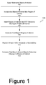
- FIG. 1 is an operational flow diagram illustrating an example process for monitoring permittivity changes of an object of interest according to one particular embodiment.
- FIG. 2A illustrates an ECT device with an object to be imaged according to one particular embodiment.
- FIG. 2B illustrates an ECT device according to one particular embodiment.
- FIG. 2C illustrates an ECT device according to one particular embodiment.
- FIG. 3A illustrates a spray coated film arranged to form a parallel-plate capacitor according to one particular embodiment.
- FIG. 3B illustrates processes to fabricate thin film sensors according to one particular embodiment.
- FIG. 4A illustrates spatial permittivity maps of a prosthesis coated with pH sensitive film according to one particular embodiment.
- FIG. 4B illustrates a graph comparing capacitance to pH values according to one particular embodiment.
- FIG. 5B illustrates spatial permittivity maps of a thin film-contained parallel plate capacitor according to one particular embodiment.
- FIG. 5C illustrates spatial permittivity maps of a thin film-contained parallel plate capacitor according to one particular embodiment.
- FIG. 6A illustrates a rod used as a human prosthesis coated with a strain-sensitive nanocomposite film subject to ECT testing according to one particular embodiment.
- FIG. 6B illustrates spatial permittivity maps of a strain sensitive film according to one particular embodiment.
- FIG. 6C illustrates a graph of a strain sensitive film comparing change in relative permittivity to strain according to one particular embodiment.
- FIG. 7 illustrates a spatial permittivity map of a prosthesis phantom subject to ECT testing according to one particular embodiment.
- FIG. 8A illustrates a rod used as a bone-prosthesis phantom subject to ECT testing as the rod was pulled out from within the bone according to one particular embodiment.
- FIG. 8B illustrates a rod used as a bone-prosthesis phantom subject to ECT testing according to one particular embodiment.
- FIG. 8C illustrates a rod used as a bone-prosthesis phantom subject to ECT testing where the bone has a crack according to one particular embodiment.
- FIG. 8D illustrates spatial permittivity maps of a bone-prosthesis, as a rod is loosened according to one particular embodiment.
- FIG. 8E illustrates spatial permittivity maps of a bone-prosthesis according to one particular embodiment.
- FIG. 8F illustrates spatial permittivity maps of a bone-prosthesis as a crack is introduced to the bone according to one particular embodiment.
- FIG. 8G illustrates a bone-prosthesis surrogate according to one particular embodiment.
- FIG. 8H illustrates spatial permittivity maps of a bone-prosthesis at different crack depths of the bone according to one particular embodiment.
- FIG. 8I illustrates a graph of a bone-prosthesis comparing change in relative permittivity to the length of a crack in the bone according to one particular embodiment.
- Embodiments of the apparatus and methods disclosed herein provide a non-contact, non-invasive technique for monitoring changes in properties of a region of interest. These changes may include, for example, changes in strain on the object of interest, changes in pH to the object of interest, or other stressors on, or around, the region of interest.
- This monitoring scheme may work in some embodiments by coupling an electrical capacitance tomography (ECT) device with stress-sensitive nanocomposite film (as an example) applied to an object of interest.
- ECT electrical capacitance tomography
- the object of interest may be incorporated into a region of interest.
- an object of interest may be a prosthetic or other implantable object, and a region of interest may be a prosthetic socket to accept a prosthetic limb after amputation.
- an object of interest may be an implanted hip, elbow, knee or other prosthetic, and the region of interest may be the surrounding tissue into which the prosthetic is implanted.
- the object of interest may be any other embeddable or implantable device with which the technology disclosed herein may be used.
- the object of interest may include part of prostheses, hulls, pipes, rods, bones, tissues, limbs, pins, sockets, or other structures.
- ECT may use applied electrical excitations to obtain readings from the nanocomposite film applied to the object of interest. Measurements from these readings (e.g., measurements at the boundaries) may be used to reconstruct the spatial permittivity distribution inside the sensing region.
- the stress-sensitive nanocomposite may pronounce permittivity changes due to changes occurring at the object of interest, thereby enhancing detection sensitivity and resolution.
- a map such as a spatial permittivity map, may be constructed from measuring the changes in properties (e.g., capacitance) over time to the object of interest. Constructed maps may be compared to a baseline map, prepared after the stress-sensitive nanocomposite film is applied to the object of interest. Changes to the maps may indicate successful incorporation or other changes to the region of interest.
- some embodiments may provide a non-contact, non-invasive system that determines changes in properties to a stress-sensitive film applied to an object of interest.
- the system can be configured to interrogate a region of interest with an electric field.
- a region of interest may include an object of interest, a stress-sensitive film, or other features.
- a stress-sensitive film may be applied to the object of interest.
- the object of interest may be a prosthesis attached to the remaining extremity of an amputated limb, which may be the region of interest.
- the system may interrogate the prosthesis and the applied stress-sensitive film and capture information.
- the system may represent this information as a spatial map depicting electrical or dielectric properties such as, for example, permittivity, as a function of position.
- This initial map may form a baseline measurement that can be used to compare against subsequent maps captured in the future. Subsequent measurements can be made after the device has been in use, and these measurements may be used to create subsequent maps. Changes in the maps may reflect a change in the prosthesis in situ, such as, for example, infection, loosening of the prosthesis, or stresses on the prosthesis.
- various other imaging devices may be used to detect changes in various properties, such as electrical properties or dielectric properties.
- Various embodiments can be implemented to not only determine changes to an object of interest, but also to determine relative changes to a stress-sensitive film on an object of interest using a non-contact, non-invasive imaging system.
- FIG. 1 is an operational flow diagram illustrating an example process for monitoring permittivity changes of an object of interest according to one particular embodiment.
- a stress-sensitive material is applied to the object of interest.
- the stress-sensitive material applied may include a thin film, nanocomposite, or thin film sensors.
- the stress-sensitive material may be sensitive to pH, strain, magnetism, electricity, heat, liquid, vibrations, or other stressors.
- the stress-sensitive material may react to the stressors as a function of a property, such as a dielectric property.
- the property may be another property, such as a magnetic property, a gravitational property, or other properties.
- the stress sensitive material may include one or more layers.
- One of the one or more layers may include an insulating primer, such that the insulating primer layer may be deposited between and directly in contact with two stress-sensitive material layers.
- the one or more layers may be otherwise arranged.
- the insulating primer may be biocompatible with the stress-sensitive material.
- the insulating primer may be composed of resin, solvent, additives, plastic, or other materials.
- the one or more layers may be deposited onto the object of interest using any of a number of techniques. For example, the layers may sprayed, as shown in FIGS. 3A and 3B , brushed, deposited, or otherwise applied to an object of interest. The material may be applied uniformly across the surface of the object of interest, as shown in FIG. 3A and portion (a) of FIG. 3B , in a pattern, as shown in portion (b) of FIG. 3B , partially applied to the object of interest, or otherwise applied.
- the stress-sensitive material may be comprised of one or more solutions.
- the one or more solutions may include, for example, polyaniline (PANI) emeraldine base, N—N dimethyl formaldehyde (DMF), deionized (DI) water, multi-walled carbon nanotubes (MWCNT), poly(sodium 4-styrenesulfonate) (PSS), latex, other elements, compounds, or solutions, or any combination of these materials.
- PANI polyaniline
- DMF N—N dimethyl formaldehyde
- DI deionized
- MWCNT multi-walled carbon nanotubes
- PSS poly(sodium 4-styrenesulfonate)
- latex other elements, compounds, or solutions, or any combination of these materials.
- PANI polyaniline
- DMF N—N dimethyl formaldehyde
- MWCNT multi-walled carbon nanotubes
- PSS poly(sodium 4-styrenesulfonate)
- the solution was prepared by dissolving a polyaniline emeraldine base into a N—N DMF solution at a concentration of around 10 mg/mL. This solution was stirred for about 24 hours with a magnetic stirrer to dissolve the PANI in the DMF. This stirred solution was then vacuum-filtered (using around 0.45 ⁇ m pore-size membrane filter) to remove undissolved particles. This filtered solution was diluted around 10-fold by adding appropriate amounts of DI water. The pH of this diluted solution was maintained to be between around 2.5 to around 2.6 using around 10% volume hydrochloric acid.
- one of the one or more solutions may include a carbon nanotube ink prepared by dispersing MWCNT in 2 wt. % PSS solution (in DI).
- the MWCNTs may be dispersed in PSS solution by ultrasonication to achieve a stable and well-dispersed suspension.
- This MWCNT-PSS ink may be mixed with PANI in equal proportions (by volume), followed by adding Kynar Aquatec ⁇ latex (i.e., the binder), to form a MWCNT-PANI/latex ink.
- one of the one or more solutions may include MWCNT dispersed by means of ultrasonication in 2 wt. % PSS solution.
- a sprayable ink may be produced by adding an appropriate amount of Kynar Aquatec ⁇ latex solution with the dispersed MWCNT-PSS solution, which can be sprayed using an airbrush.
- the object of interest with the applied stress-sensitive material may be incorporated into a region of interest.
- the region of interest may be adapted to receive the object of interest with the applied stress-sensitive material.
- the object of interest may be the remaining part of the region of interest.
- the object of interest with the applied stress-sensitive material may be a part of a prosthesis and the region of interest may be remaining extremity of an amputated limb configured to receive the part of the prosthesis via surgery or otherwise.
- the object of interest with the applied stress-sensitive material may be a pin on the prosthesis and the region of interest may be a socket configured to receive the pin when the prosthesis is applied to the extremity.
- the region of interest with the applied stress-sensitive material may be inserted into an ECT device and the ECT device used to interrogate the region of interest. Interrogation may occur by applying a voltage signal to the electrodes, as described herein.
- Other imaging devices may be used that are sensitive to electric fields. Electrical capacitance tomography is a soft field imaging technique through which permittivity distribution inside a predefined sensing domain can be reconstructed from capacitance measurements at the boundary electrodes.
- each electrode may be separately used for exciting the sensing domain with a time-varying electric field, while others may be grounded. Mutual capacitance between pairs of excitation and grounded electrodes may be measured simultaneously, as in portion (b) of FIG. 2B .
- capacitance data may be used as inputs for solving an inverse problem to reconstruct the permittivity distribution of the sensing domain.
- the forward problem may solve a system of linear equations to calculate the boundary capacitance responses from a priori knowledge of the permittivity distribution, boundary conditions, and sensing domain geometry.
- the inverse problem may reconstruct the permittivity distribution of the sensing domain from the measured set of boundary capacitance responses. The formulations of forward and inverse problems is described herein.
- the ECT algorithm comprises of the forward and inverse problems.
- the forward problem may calculate the capacitance response at the boundary electrodes given a known electrical field excitation and spatial permittivity distribution of the sensing region.
- the inverse problem may seek to reconstruct the sensing region's permittivity distribution using the set of boundary capacitance measurements when the sensing region is interrogated using different patterns of applied electrical fields.
- the forward problem may be solved in order to calculate the boundary capacitance response when the permittivity distribution inside the sensing domain ( ⁇ ) is known. Solving the forward problem may allow calculation of the capacitance between the excitation and sensing electrodes.
- This second-order partial differential equation may be solved with appropriate boundary conditions as described in Eq. (2) so as to estimate the potential distribution everywhere in ⁇ .
- the finite element method (FEM) may be adopted to solve Eq. (1).
- the corresponding weak-form of the ECT forward problem may be derived by multiplying Eq. (1) with sufficiently smooth test function, v, and then integrating over ⁇ .
- the inverse problem may be employed for reconstructing the permittivity distribution of ⁇ using the set of experimental capacitance measurements at the boundary electrodes due to different boundary electrical field excitations.
- a Gauss-Newton iterative algorithm may be implemented to minimize the error between computationally obtained (Cc) and experimental capacitance measurements (Cm).
- the inverse problem may start with an initial assumed permittivity distribution. It should be clarified that Cc may be found by solving the forward problem using the assumed permittivity distribution of ⁇ .
- the ECT inverse problem may be non-linear and ill-posed by nature, and proper regularization should be adopted to ensure smooth convergence of the inverse algorithm.
- a Tikhonov regularization technique may be implemented.
- the ECT device as shown in the example of FIGS. 2A, 2B, and 2C may be configured in a circular shape with an electrode array mounted around the perimeter. In other embodiments, the ECT device may have other geometries or shapes.
- FIG. 2A illustrates an example ECT device with an object to be imaged according to one particular embodiment.
- Object 210 may be placed within ECT device 200 .
- Excitation and sensing electrodes 206 may be configured as a circular ring or track in some embodiments. The electrodes may be otherwise arranged to conform to the shape and structure of the ECT device.
- Low amplitude electric fields can be injected between excitation and sensing electrodes 206 mounted on pipe 204 . As a result, the electric field may then interact with the object 210 .
- the raw data collected can be fed as input to an ECT algorithm to back calculate spatial permittivity maps that describe the electrical properties of the cross-section interrogated by the ECT system.
- the ECT device may also permit the identification of shapes, sizes, and locations of features of interest within the region of interest.
- the ECT device may be able to distinguish human tissue, a prosthesis, and an infected region from each other, further allowing for detailed identification and information about any possible changes occurring at the region of interest.
- the ECT device can be used to apply medical imaging properties to determine the electrical or dielectric properties of objects of interest implanted within a region of interest.
- the ECT device can be used for monitoring deformations or changes in structures, such as pins, sockets, hulls, pipes, beams, or other structures.
- FIG. 2B illustrates an ECT device according to one particular embodiment.
- the ECT device may include a sensing region that may be defined by a set of non-contact electrodes arranged in a typically circular array, similar to FIG. 2A .
- An alternating current electrical excitation may be applied at one electrode, while the remaining electrodes are grounded, such as the example illustrated in portion (b) of FIG. 2B .
- an electrical field may be propagated between the excitation and all other sensing electrodes.
- an electric field is allowed to propagate through ⁇ as depicted in portion (b) of FIG. 2B .
- FIG. 2C illustrates an ECT device according to one particular embodiment.
- FIG. 2C may be substantially the same as FIGS. 2A and 2B .
- the data obtained during interrogation of the region of interest may be used to generate a first map.
- a series of cross-sections of the region of interest may be captured by the system and a map generated for each cross-section.
- the first map may be one or more of a spatial permittivity map, a graph, a chart, or other representations of data. This first map can be stored and retained as a reference point indicating a map for the object of interest in the region of interest in its newly implanted condition—before stressors have had the opportunity to materially impact the object of interest.
- the ECT device may also be used on objects of interest that do not have a stress-sensitive material.
- a plastic rod may be used as an object of interest.
- the plastic rod may be subject to uniaxial and bending loads, while dielectric property changes due to deformation may be monitored with ECT.
- a load frame may be customized to apply different types of loads (e.g., uniaxial compression and bending) on the plastic rod.
- Rotary tables and four-jaw adjustable chucks may be used to apply force to the plastic rod.
- the plastic rod may be fitted into the load frame through the four-jaw-chuck such that the plastic rod is fixed at one end and free at the other.
- the rod may be placed into the ECT electrode array, such that the rod is located at the middle of the ECT electrode array.
- a set of baseline capacitance measurement may be obtained and the corresponding permittivity distribution (i.e., baseline) may be reconstructed from the measured set of data. Change in permittivity distributions with respect to the baseline due to the application of loads may
- a battery of tests may be applied to the object of interest with the applied stress-sensitive material, such that maps corresponding to each test may be generated.
- the maps may be used to compare against subsequent changes to the object of interest with the applied stress-sensitive material, therefore, the approximate changes to the object of interest with the applied stress-sensitive material may be estimated.
- a battery of tests may not be appropriate and the object of interest with the applied stress-sensitive material may be incorporated directly into the region of interest.
- the battery of tests may also be applied to the object of interest that does not have stress-sensitive material.
- operations 106 and 108 may be repeated after a first length of time to generate a second map.
- a second map For example, after the device has been implanted or used for a period of time, new measurements can be made and maps generated to depict the characteristics of the region of interest.
- the first map may be compared to the second map to determine any changes to the region of interest.
- Operations 110 and 112 may continue to be repeated such that subsequent measurements and comparisons can be repeated at various points in time to measure the region of interest overtime.
- Maps generated can be compared with each other to identify changes over time or to identify stresses that may have occurred. For example, subsequent maps can be compared back to the baseline or reference map and changes can be studied to determine whether there are any issues with the object of interest, the region of interest, or both.
- the maps can be compared visually by an operator while in other embodiments the comparison can be performed by or assisted by automated image processing techniques that can be used to compare the maps and output any changes.
- the differences may suggest that the incorporation of the object of interest with the applied stress-sensitive material into the region of interest may not have been successful. In one embodiment, the differences may inform a healthcare practitioner that adjustments to the object of interest may be needed.
- the differences may indicate how a stressor has affected the object of interest with the applied stress-sensitive material.
- a stress-sensitive material sensitive to pH may have been applied to the object of interest which was incorporated into a region of interest. Comparing a second map to a first map of the region of interest may indicate changes, such that the pH of the area surrounding, or on, the object of interest with the applied stress-sensitive material has become more basic. The higher pH may indicate an infection on, or around, the object of interest with the applied stress-sensitive material. A lower pH may indicate an infection as well.
- the differences may indicate unsuccessful incorporation of the object of interest with the applied stress-sensitive material into the region of interest, such that the object of interest with the applied stress-sensitive material should be removed.
- the region of interest or object of interest with the applied stress-sensitive material may be treated or otherwise modified to return the object of interest with the applied stress-sensitive material to the same pH levels represented in the first map.
- the similarity may indicate successful incorporation of the object of interest with the applied stress-sensitive material into the region of interest.
- the region of interest may continue to be monitored.
- FIG. 3A illustrates a spray coated film arranged to form a parallel-plate capacitor according to one particular embodiment.
- a pH-sensitive thin film may be fabricated using carbon nanotubes (CNT) and PANI and then applied onto an object of interest.
- CNT carbon nanotubes
- a diluted and pH-adjusted PANI solution with a dispersed CNT solution may be created so that non-composite thin film pH sensors can be fabricated by spray-painting it onto any surface.
- MWCNT may be dispersed in 2 wt % PSS solution by ultrasonication.
- the PANI solution and the dispersed MWCNT-PSS solution may be mixed together in equal proportions.
- MWCNT-PANI/latex nanocomposites may then be employed as sensors, or stress-sensitive materials.
- any type of brush or spraying method known by a person of ordinary skill in the art may be used to distribute the MWCNT onto the structures.
- the MWCNT-PANI/latex nanocomposites are sensitive to different stressors, the MWCNT-PANI/latex nanocomposites can be used with the ECT device for mapping an object of interest to monitor changes to the object of interest with the applied stress-sensitive material.
- the MWCNT-PANI/latex nanocomposites can be applied to objects of interest for monitoring changes due to various stressors, such as pH or strain.
- a pH-sensitive thin film may be fabricated using MWCNT and PANI.
- the thin film's pH sensitivity may be characterized by exposing it to different pH buffer solutions and measuring its corresponding dielectric property changes.
- a circular plastic rod may be used as a phantom for a human prosthesis, for example, to simulate the portion of an artificial limb that would be embedded in and bonded to the human body.
- the thin film may be deposited onto the surface of the prosthetic phantom and exposed to different pH buffer solutions.
- the ECT system may be used to interrogate the prosthetic phantom placed in the sensing area.
- FIG. 3A may illustrate that the film, glass slides, and aluminum tape electrodes can be arranged to from a parallel plate capacitor test set-up.
- An alternating current signal may be injected, thus allowing the system's current response to be recorded.
- the system may detect changes in permittivity due to different pH buffers, and the reconstructed permittivity maps may identify the location of the permittivity changes, as well as the location of the prosthesis itself.
- the ECT device with a pH-sensitive thin film can be used to effectively image and detect properties of dielectric properties of human tissues to monitor skin and tissue infections.
- FIG. 3B illustrates processes to fabricate thin film sensors according to one particular embodiment.
- spray coating techniques may be adopted to fabricate strain-sensitive nanocomposite thin films.
- MWCNT may be dispersed by means of ultrasonication in about 2 wt. % PSS solution.
- a sprayable ink may be produced by adding an appropriate amount of Kynar Aquatec ⁇ latex solution with the dispersed MWCNT-PSS solution, which can be sprayed using an airbrush as used in this work.
- the MWCNT-latex thin film can be spray coated onto different types structural surfaces and it can serve as a distributed strain sensor.
- the thin films may be deposited on the transparent Polyethylene terephthalate (PET) sheet and specimens may be made for their strain sensitivity characterization.
- the nanocomposite thin film can be increased by changing the deposition patterns of MWCNT-latex thin film and the insulating primer.
- a layer of insulating paint primer may be deposited onto a PET sheet.
- a separate layer of MWCNT-latex thin film may be deposited onto the primer surface by airbrushing.
- Another layer of insulating primer may be deposited on the top of the MWCNT-latex thin film, as shown in portion (a) of FIG. 3B .
- the fabrication of a thin film may be started by depositing a layer of insulating primer on the top of a PET sheet.
- Blue masking tapes of about 4 millimeter thickness, may be fixed onto primer-coated surface for patterned deposition of the MWCNT-latex ink. The tape may be fixed so the distance between two consecutive parallel tapes may be about 4 millimeters.
- a layer of MWCNT-latex thin film may be airbrushed on the masked surface of primer-coated PET.
- the masking tapes may be removed and another layer of primer may be spray coated on the top of the final surface.
- Alternative layers of conductive MWCNT-latex thin film and insulating primer may serve as a compound parallel plate capacitor.
- the strain sensing response of the nanocomposite thin film may be enhanced as a result.
- the fabrication process may be accomplished using robotic spray fabrication tools for covering structural surfaces.
- the thin film may be fabricated with different material using a different process.
- FIG. 4A illustrates spatial permittivity maps of a prosthesis coated with pH sensitive film according to one particular embodiment.
- a plastic rod may be used as a human prosthesis coated with a pH-sensitive nanocomposite film subject to ECT testing.
- Monitoring for infection occurring at the prosthesis interface may involve two aspects. The first may be the use of a pH-sensitive MWCNT-PANI/latex thin film, which could be applied at the human-prosthesis interface for monitoring pH changes resulting from infection.
- the fabrication process for the pH-sensitive MWCNT-PANI/latex thin film may be described in greater detail herein and may be shown in FIG. 3A .
- the second is the implementation of a soft field imaging technique based on the electrical capacitance tomography algorithm, which may use boundary electrical field excitations and capacitance measurements for reconstructing the spatial permittivity of the sensing area enclosed by an array of electrodes arranged in a circular pattern.
- the device may be an ECT device, as shown in FIGS. 2A, 2B, and 2C , or another imaging device.
- the maps (portions (a)-(f)) indicate the object of interest with the applied stress-sensitive material was exposed to environment conditions with a pH of 9, 11, and 13, which may be infection conditions.
- the permittivity map, or distribution, corresponding to the pH 7 case may be a baseline.
- the baseline may be subtracted from all other permittivity distributions (for other pH cases).
- the permittivity of the region of interest corresponding to where the object of interest with the applied stress-sensitive material was located may increase as the prosthesis is exposed to more alkaline pH buffer solutions.
- FIG. 4B illustrates a graph comparing capacitance to pH values according to one particular embodiment.
- the stress-sensitive material may change in properties in reaction to stressors. For example, the capacitance of the stress-sensitive material increased as the pH increased. The capacitance may increase as a result in the change of a dielectric property of the stress-sensitive material.
- FIG. 5A illustrates a thin film-contained parallel plate capacitor subject to ECT testing according to one particular embodiment.
- the thin film may be fabricated in a way described herein, such as shown in FIG. 3B .
- the thin films may be cut into proper sizes and assembled to form a parallel plate capacitor sensitive to strain.
- Thin film-coated PET 506 may be cut into a strip and put into a load frame.
- Adhesive copper tape 502 may be affixed on a side of pristine PET strips 504 of similar size, and attached on both sides of thin film-coated PET strip 506 which was clamped to a load frame.
- Such arrangement of thin film-coated PET 506 , copper tape 502 , and PET strips 504 may form a parallel plate capacitor with thin film as dielectric medium between two parallel electrodes (not shown).
- the electrodes (not shown) may be externally attached to prevent deformation while thin film-coated PET 506 is subjected to load. Uniaxial tensile strain may be applied to the parallel plate capacitor. The capacitances of the parallel plate capacitors made from stress-sensitive material may be measured.
- FIG. 5B illustrates spatial permittivity maps of a thin film-contained parallel plate capacitor according to one particular embodiment.
- the strain sensitivity of a first thin film may be lower than that of a second thin film (portions (h)-(n) of FIG. 5B ).
- the signal-to-noise ratio may be higher (i.e. the magnitude of the change in electrical permittivity is larger) for the second thin film when subjected to uniaxial loading and unloading than the first thin film.
- the first thin film may be applied evenly to an object of interest and the second thin film may be applied in a pattern to an object of interest.
- the first thin film may be fabricated in a process similar to that shown in portion (a) of FIG. 3B and the second thin film may be fabricated in a process similar to that shown in portion (b) of FIG. 3B .
- FIG. 5C illustrates spatial permittivity maps of a thin film-contained parallel plate capacitor according to one particular embodiment.
- the strain sensitivity of a first thin film may be lower than that of a second thin film (portions (h)-(n) of FIG. 5B ).
- the signal-to-noise ratio may be higher (i.e. the magnitude of the change in electrical permittivity is larger) for the second thin film when subjected to uniaxial loading and unloading than the first thin film.
- a bipolar change in electrical permittivity may occur on the second thin film.
- the first thin film may be applied evenly to an object of interest and the second thin film may be applied in a pattern to an object of interest.
- the first thin film may be fabricated in a process similar to that shown in portion (a) of FIG. 3B and the second thin film may be fabricated in a process similar to that shown in portion (b) of FIG. 3B .
- FIG. 6A illustrates a rod used as a human prosthesis coated with a strain-sensitive nanocomposite film subject to ECT testing according to one particular embodiment.
- the strain-sensitive nanocomposite film may be applied through various methods. For example, a layer of insulating paint primer 602 may be deposited onto prosthesis phantom 606 . MWCNT-latex thin film 604 may be spray coated multiple time to form a ring of layers, as shown in FIG. 6A . Other processes, such as those described herein, may be used.
- the film used may have a permittivity that is sensitive to applied strains.
- the nanocomposite physically represents a multilayered structure with alternating layers of MWCNT-latex thin films 604 and insulating paint primer 602 , as shown in portion (a) of FIG. 6A .
- the multilayered MWCNT-latex thin film 604 (which represents stacked parallel-plate capacitors) may change its thickness due to Poisson's effect, which in turn may cause the dielectric properties or the perceived permittivity of the system to change.
- tissue-bone-prosthesis surrogate may be used.
- the tissue-bone-prosthesis surrogate may include a sawbone femur, an aluminum rod, water-saturated foam, stress-sensitive material, and other materials.
- the tissue-bone-prosthesis surrogate may be interrogated.
- FIG. 6B illustrates spatial permittivity maps of a strain sensitive film according to one particular embodiment.
- Portions (a)-(e) may show the reconstructed spatial permittivity maps of the entire sensing domain for a pristine rod (without a stress-sensitive material) subject to different magnitudes of tensile strains. Note that these ECT results may be changes in permittivity relative to the permittivity distribution of the unloaded prosthesis phantom in air; hence, the rod itself may not be shown.
- Portions (f)-(j) may show the reconstructed spatial permittivity maps of the entire sensing domain for a film-coated prosthesis phantom (with an applied strain-sensitive material) subject to different magnitudes of tensile strains.
- the film-coated prosthesis phantom may be similar to the one in FIG. 6A .
- the ECT results for the film-coated prosthesis phantom may show strain-induced permittivity changes. The location of these permittivity changes may correspond to where the film-coated prosthesis phantom was physically in the sensing domain.
- FIG. 6C illustrates a graph of a strain sensitive film comparing change in relative permittivity to strain according to one particular embodiment.
- the data used for the graph may be a result of the system described in FIG. 6A .
- the maximum change in permittivity was obtained at each strain state which may indicate the linear dependence of permittivity with respect to strain.
- FIG. 7 illustrates a spatial permittivity map of a prosthesis phantom subject to ECT testing according to one particular embodiment.
- the prosthesis phantom may include a lamb shank and a rod.
- the spatial permittivity map may indicate the position and relative permittivity of the prosthesis phantom within a sensing area of an ECT device, as shown in FIGS. 2A, 2B, and 2C .
- FIG. 8A illustrates a rod used as a bone-prosthesis phantom subject to ECT testing as the rod was pulled out from within the bone according to one particular embodiment.
- the object of interest may simulate an osseointergrated prosthesis ( 01 P) surrogate.
- the OIP surrogate may include a poly(vinyl chloride) (PVC) rod, a femur sawbone, and other materials.
- An ECT device may be used to interrogate the OIP surrogate as shown in portion (a) of FIG. 8A .
- the rod may be gradually pulled out from the femur sawbone starting from around 0 mm to around 35 mm.
- the system may have been interrogated by the ECT system, and the corresponding electrical permittivity distributions may have been reconstructed from the measured set of boundary capacitance responses, as shown in FIG. 8D .
- FIG. 8B illustrates a rod used as a bone-prosthesis phantom subject to ECT testing according to one particular embodiment.
- Prosthesis loosening if undetected at an early stage, can cause stress concentrations in bone and, ultimately, cracks (or fracture) can propagate at the bone-prosthesis interface, thereby leading to OIP failure and extreme pain for an amputee.
- a sawbone femur may be included in the OIP surrogate.
- the OIP surrogate may further include an aluminum rod, epoxy, or other materials.
- a slit, or crack may be cut along the side and in the direction of the longitudinal axis of the femur, as shown in portions (c) and (d) of FIG. 8B .
- the surrogate may be interrogated by an ECT device, as described herein.
- FIG. 8C illustrates a rod used as a bone-prosthesis phantom subject to ECT testing where the bone has a crack according to one particular embodiment.
- the bone-prosthesis phantom may be similar to the one shown in FIGS. 8A and 8B .
- Portion (a) of FIG. 8C may illustrate a printed mold that may be used to hold the bone-prosthesis phantom in an ECT device.
- Portion (a) may illustrate a crack on the bone-prosthesis phantom.
- Portion (b) of FIG. 8C illustrates the bone-prosthesis phantom within an ECT device, as described herein.
- FIG. 8D illustrates spatial permittivity maps of a bone-prosthesis, as a rod is loosened according to one particular embodiment.
- the spatial permittivity maps illustrate different measurement taken as a rod within a bone-prosthesis phantom, as shown in FIGS. 8A, 8B, and 8C , may have been removed from the bone-prosthesis phantom at around 5 millimeters, around 10 millimeters, around 15 millimeters, around 20 millimeters, around 25 millimeters, around 30 millimeters, and around 35 millimeters.
- the measurements may have been compared against a baseline (e.g., no loosening or removal) to generate the permittivity maps of FIG. 8D .
- FIG. 8E illustrates spatial permittivity maps of a bone-prosthesis according to one particular embodiment.
- the spatial permittivity maps illustrate different measurement taken as a fracture, or crack, may have been introduced on a bone-prosthesis phantom, as shown in FIGS. 8A, 8B, and 8C .
- Portion (a) of FIG. 8E may illustrate a pristine OIP surrogate, while portion (b) of FIG. 8E may illustrate the changes in permittivity distribution due to the crack.
- the measurement of portion (b) of FIG. 8E may have been compared against a baseline (e.g., no crack in the OIP surrogate) to generate the permittivity map of portion (b) of FIG. 8E .
- a baseline e.g., no crack in the OIP surrogate
- FIG. 8F illustrates spatial permittivity maps of a bone-prosthesis as a crack is introduced to the bone according to one particular embodiment.
- the spatial permittivity maps illustrate different measurement taken as a fracture, or crack, may have been introduced on the longitudinal direction of the OIP surrogate, as shown in FIGS. 8A, 8B, and 8C .
- the crack may have been introduced in increments of around 2.85 millimeters, around 5.70 millimeters, around 8.52 millimeters, around 11.40 millimeters, and around 14.25 millimeters.
- the measurements may have been compared against a baseline (e.g., no crack in the OIP surrogate) to generate the permittivity maps of FIG. 8F .
- FIG. 8G illustrates a bone-prosthesis surrogate according to one particular embodiment.
- Portion (a) of FIG. 8G may illustrate a diagram of an OIP surrogate in an ECT device.
- the OIP surrogate may be similar to that shown in FIGS. 8A, 8B, and 8C .
- the ECT device may be similar to that shown in FIGS. 2A, 2B, and 2C .
- Various dimensions may be used to describe parts of the OIP surrogate. However, the dimensions of the parts of the OIP surrogate may be different.
- the prosthesis may be around 14 millimeters.
- the distance from the prosthesis to a first edge of the sawbone may be around 10 millimeters.
- the distance from the prosthesis to a second edge of the sawbone may be around 15 millimeters.
- the distance from the prosthesis to a third edge of the sawbone may be around 10 millimeters.
- the distance from the prosthesis to a fourth edge of the sawbone may be around 5 millimeters.
- Portion (b) of FIG. 8G may illustrate measurements taken of the set-up describe above. For example, the measurement may have been modeled by FEM and discretized using linear triangular elements. FEM may be used to help solve Eq. (1) (the 2D Laplace equation).
- Portion (c) of FIG. 8G may illustrate elements of portion (b) reconstructed by a limited region tomographic (LRT) image reconstruction algorithm.
- LRT limited region tomographic
- the main objective of LRT may be to enhance the imaging performance of the inverse algorithm by limiting the reconstruction region to a particular zone where changes in electrical permittivity may be expected to occur. In doing so, the number of unknown image pixels can be significantly reduced with LRT imaging.
- FIG. 8H illustrates spatial permittivity maps of a bone-prosthesis at different crack depths of the bone according to one particular embodiment.
- the spatial permittivity maps illustrate different measurement taken as a fracture, or crack, may have been introduced on the longitudinal direction of the OIP surrogate, as shown in FIGS. 8A, 8B, and 8C .
- the crack may have been introduced in increments of around 2.85 millimeters, around 5.70 millimeters, around 8.52 millimeters, around 11.40 millimeters, and around 14.25 millimeters.
- the measurements may have been compared against a baseline (e.g., no crack in the OIP surrogate) to generate the permittivity maps of FIG. 8H .
- LRT image reconstruction algorithms may have been used to generate the permittivity maps of FIG. 8H .
- the spatial permittivity maps, as shown in FIG. 8H may illustrate gradual shape changes observed near the location of the fracture, which may correspond to the depth of the fracture increasing.
- the shape of the change in electrical permittivity may resemble the cross-sectional shape of the fracture.
- FIG. 8I illustrates a graph of a bone-prosthesis comparing change in relative permittivity to the length of a crack in the bone according to one particular embodiment.
- the graph may illustrate different measurement taken as a fracture, or crack, may have been introduced on the longitudinal direction of the OIP surrogate, as shown in FIGS. 8A, 8B, and 8C .
- the maximum change in permittivity was obtained at different crack points.
- the graph may indicate a decrease in the maximum change of relative permittivity as the length of the crack in the OIP surrogate increases.
- module does not imply that the components or functionality described or claimed as part of the module are all configured in a common package. Indeed, any or all of the various components of a module, whether control logic or other components, may be combined in a single package or separately maintained and may further be distributed in multiple groupings or packages or across multiple locations.
- module does not imply that the components or functionality described or claimed as part of the module are all configured in a common package. Indeed, any or all of the various components of a module, whether control logic or other components, can be combined in a single package or separately maintained and can further be distributed in multiple groupings or packages or across multiple locations.
Landscapes
- Health & Medical Sciences (AREA)
- Life Sciences & Earth Sciences (AREA)
- Physics & Mathematics (AREA)
- General Health & Medical Sciences (AREA)
- Engineering & Computer Science (AREA)
- Nuclear Medicine, Radiotherapy & Molecular Imaging (AREA)
- Pathology (AREA)
- Veterinary Medicine (AREA)
- General Physics & Mathematics (AREA)
- Heart & Thoracic Surgery (AREA)
- Medical Informatics (AREA)
- Molecular Biology (AREA)
- Surgery (AREA)
- Animal Behavior & Ethology (AREA)
- Biophysics (AREA)
- Public Health (AREA)
- Radiology & Medical Imaging (AREA)
- Chemical & Material Sciences (AREA)
- Biomedical Technology (AREA)
- Power Engineering (AREA)
- Chemical Kinetics & Catalysis (AREA)
- Electrochemistry (AREA)
- Analytical Chemistry (AREA)
- Biochemistry (AREA)
- Immunology (AREA)
- Dermatology (AREA)
- Investigating Or Analyzing Materials By The Use Of Electric Means (AREA)
- Prostheses (AREA)
Abstract
Description
∇·(ε∇u)=0 (1)
where ε and u are the electrical permittivity and electric potential distributions inside Ω, respectively. This second-order partial differential equation may be solved with appropriate boundary conditions as described in Eq. (2) so as to estimate the potential distribution everywhere in Ω. The finite element method (FEM) may be adopted to solve Eq. (1). The corresponding weak-form of the ECT forward problem may be derived by multiplying Eq. (1) with sufficiently smooth test function, v, and then integrating over Ω.
Claims (14)
Priority Applications (1)
| Application Number | Priority Date | Filing Date | Title |
|---|---|---|---|
| US15/890,087 US11083393B2 (en) | 2017-02-06 | 2018-02-06 | Non-contact tomographic imaging and thin film sensors for sensing permittivity changes |
Applications Claiming Priority (2)
| Application Number | Priority Date | Filing Date | Title |
|---|---|---|---|
| US201762455454P | 2017-02-06 | 2017-02-06 | |
| US15/890,087 US11083393B2 (en) | 2017-02-06 | 2018-02-06 | Non-contact tomographic imaging and thin film sensors for sensing permittivity changes |
Publications (2)
| Publication Number | Publication Date |
|---|---|
| US20180220920A1 US20180220920A1 (en) | 2018-08-09 |
| US11083393B2 true US11083393B2 (en) | 2021-08-10 |
Family
ID=63038453
Family Applications (1)
| Application Number | Title | Priority Date | Filing Date |
|---|---|---|---|
| US15/890,087 Active 2039-08-12 US11083393B2 (en) | 2017-02-06 | 2018-02-06 | Non-contact tomographic imaging and thin film sensors for sensing permittivity changes |
Country Status (1)
| Country | Link |
|---|---|
| US (1) | US11083393B2 (en) |
Cited By (1)
| Publication number | Priority date | Publication date | Assignee | Title |
|---|---|---|---|---|
| US11300558B2 (en) * | 2018-06-14 | 2022-04-12 | Nokomis, Inc. | Apparatus and system for spectroscopy and tomography of fragile biologic materials |
Families Citing this family (6)
| Publication number | Priority date | Publication date | Assignee | Title |
|---|---|---|---|---|
| WO2020041593A1 (en) * | 2018-08-23 | 2020-02-27 | The General Hospital Corporation | System and method for monitoring implant fixation using electrical impedance tomography |
| CN111175355B (en) * | 2018-11-13 | 2021-06-22 | 中国科学院大连化学物理研究所 | Capacitance tomography sensor and system for high temperature fluidized bed measurement |
| US11716543B2 (en) | 2019-06-20 | 2023-08-01 | Cilag Gmbh International | Wide dynamic range using a monochrome image sensor for fluorescence imaging |
| US11624830B2 (en) | 2019-06-20 | 2023-04-11 | Cilag Gmbh International | Wide dynamic range using a monochrome image sensor for laser mapping imaging |
| US11622094B2 (en) | 2019-06-20 | 2023-04-04 | Cilag Gmbh International | Wide dynamic range using a monochrome image sensor for fluorescence imaging |
| CN111176496B (en) * | 2019-12-31 | 2021-10-08 | 北京航空航天大学 | A capacitive sensor and method for determining touch screen positioning by capacitive imaging |
Citations (9)
| Publication number | Priority date | Publication date | Assignee | Title |
|---|---|---|---|---|
| US20040122790A1 (en) * | 2002-12-18 | 2004-06-24 | Walker Matthew J. | Computer-assisted data processing system and method incorporating automated learning |
| US20090121727A1 (en) * | 2007-09-14 | 2009-05-14 | The Regents Of The University Of Michigan | Electrical impedance tomography of nanoengineered thin films |
| US20140365152A1 (en) * | 2013-05-30 | 2014-12-11 | Tech4Imaging Llc | Interactive and Adaptive Data Acquisition System for Use with Electrical Capacitance Volume Tomography |
| US20150044656A1 (en) * | 2014-09-23 | 2015-02-12 | 7-Sigma, Inc. | Electrically conductive nanotube composite sensor for medical application |
| US20150066415A1 (en) * | 2013-05-10 | 2015-03-05 | United States Of America As Represented By The Secretary Of The Navy | Apparatus and Method for Measuring Microelectronic Electromagnetic Emissions to Detect Characteristics |
| US20160091448A1 (en) * | 2013-05-13 | 2016-03-31 | The University Of Bath | Apparatus and method for measuring electromagnetic properties |
| US20160238547A1 (en) * | 2013-10-15 | 2016-08-18 | 1835963 Alberta Ltd. | Sensing Element Compositions and Sensor System for Detecting and Monitoring Structures for Hydrocarbons |
| US20170105648A1 (en) * | 2015-10-20 | 2017-04-20 | General Electric Company | Detection of physiological changes in impedance monitoring |
| US20170323461A1 (en) * | 2014-06-17 | 2017-11-09 | Fraunhofer-Gessellschaft zur Förderung der angewandten Forschung e.V. | Method and evaluation device for evaluating projection data of an object being examined |
-
2018
- 2018-02-06 US US15/890,087 patent/US11083393B2/en active Active
Patent Citations (9)
| Publication number | Priority date | Publication date | Assignee | Title |
|---|---|---|---|---|
| US20040122790A1 (en) * | 2002-12-18 | 2004-06-24 | Walker Matthew J. | Computer-assisted data processing system and method incorporating automated learning |
| US20090121727A1 (en) * | 2007-09-14 | 2009-05-14 | The Regents Of The University Of Michigan | Electrical impedance tomography of nanoengineered thin films |
| US20150066415A1 (en) * | 2013-05-10 | 2015-03-05 | United States Of America As Represented By The Secretary Of The Navy | Apparatus and Method for Measuring Microelectronic Electromagnetic Emissions to Detect Characteristics |
| US20160091448A1 (en) * | 2013-05-13 | 2016-03-31 | The University Of Bath | Apparatus and method for measuring electromagnetic properties |
| US20140365152A1 (en) * | 2013-05-30 | 2014-12-11 | Tech4Imaging Llc | Interactive and Adaptive Data Acquisition System for Use with Electrical Capacitance Volume Tomography |
| US20160238547A1 (en) * | 2013-10-15 | 2016-08-18 | 1835963 Alberta Ltd. | Sensing Element Compositions and Sensor System for Detecting and Monitoring Structures for Hydrocarbons |
| US20170323461A1 (en) * | 2014-06-17 | 2017-11-09 | Fraunhofer-Gessellschaft zur Förderung der angewandten Forschung e.V. | Method and evaluation device for evaluating projection data of an object being examined |
| US20150044656A1 (en) * | 2014-09-23 | 2015-02-12 | 7-Sigma, Inc. | Electrically conductive nanotube composite sensor for medical application |
| US20170105648A1 (en) * | 2015-10-20 | 2017-04-20 | General Electric Company | Detection of physiological changes in impedance monitoring |
Cited By (1)
| Publication number | Priority date | Publication date | Assignee | Title |
|---|---|---|---|---|
| US11300558B2 (en) * | 2018-06-14 | 2022-04-12 | Nokomis, Inc. | Apparatus and system for spectroscopy and tomography of fragile biologic materials |
Also Published As
| Publication number | Publication date |
|---|---|
| US20180220920A1 (en) | 2018-08-09 |
Similar Documents
| Publication | Publication Date | Title |
|---|---|---|
| US11083393B2 (en) | Non-contact tomographic imaging and thin film sensors for sensing permittivity changes | |
| Kolehmainen et al. | Assessment of errors in static electrical impedance tomography with adjacent and trigonometric current patterns | |
| Liu et al. | Estimation of conductivity changes in a region of interest with electrical impedance tomography | |
| US8159235B2 (en) | Electrical impedance tomography of nanoengineered thin films | |
| Gupta et al. | Noncontact electrical permittivity mapping and pH-sensitive films for osseointegrated prosthesis and infection monitoring | |
| Ghaednia et al. | Interfacial load monitoring and failure detection in total joint replacements via piezoresistive bone cement and electrical impedance tomography | |
| Jiang et al. | Capacitively coupled resistivity imaging for biomaterial and biomedical applications | |
| Gupta et al. | Monitoring osseointegrated prosthesis loosening and fracture using electrical capacitance tomography | |
| Bera et al. | A FEM-based forward solver for studying the forward problem of electrical impedance tomography (EIT) with a practical biological phantom | |
| Li et al. | Development of a portable and low-cost data acquisition system with edge intelligence for electrical impedance tomography-based spatial damage detection | |
| Pugach et al. | Electronic hardware design of a low cost tactile sensor device for physical human-robot interactions | |
| CN118510441A (en) | Improved electrical tomography measuring device | |
| Pyo et al. | A wireless impedance analyzer for automated tomographic mapping of a nanoengineered sensing skin | |
| Borsic et al. | Realistic 2D human thorax modelling for EIT | |
| CN116824048B (en) | A sensor, Jacobian matrix solution method, three-dimensional imaging system and method | |
| Liu et al. | Development of electrical impedance tomography system for cell sedimentation detection in electrode-multilayered microchannel | |
| Farooq et al. | Improvements and artifact analysis in conductivity images using multiple internal electrodes | |
| Gupta et al. | Non-contact tomographic imaging and nanocomposite thin films for monitoring human-prosthesis interfaces | |
| Bera et al. | Thin domain wide electrode (TDWE) phantoms for Electrical Impedance Tomography (EIT) | |
| Jeong et al. | Integration of piezo-capacitive and piezo-electric nanoweb based pressure sensors for imaging of static and dynamic pressure distribution | |
| Wang et al. | Application of digital image correlation for multiscale biomechanics | |
| Dehghani et al. | Numerical modelling errors in electrical impedance tomography | |
| Naik et al. | Simulation of forward problem for non-invasive two dimensional electrical impedance tomography system using EIDORS and COMSOL multiphysics | |
| Gupta et al. | Noncontact tomography and a pH-sensitive nanocomposite for monitoring osseointegrated prosthesis interfaces | |
| Rymarczyk et al. | Monitoring damage and dampness in flood embankment by electrical impedance tomography |
Legal Events
| Date | Code | Title | Description |
|---|---|---|---|
| FEPP | Fee payment procedure |
Free format text: ENTITY STATUS SET TO UNDISCOUNTED (ORIGINAL EVENT CODE: BIG.); ENTITY STATUS OF PATENT OWNER: SMALL ENTITY |
|
| FEPP | Fee payment procedure |
Free format text: ENTITY STATUS SET TO SMALL (ORIGINAL EVENT CODE: SMAL); ENTITY STATUS OF PATENT OWNER: SMALL ENTITY |
|
| STPP | Information on status: patent application and granting procedure in general |
Free format text: DOCKETED NEW CASE - READY FOR EXAMINATION |
|
| AS | Assignment |
Owner name: THE REGENTS OF THE UNIVERSITY OF CALIFORNIA, CALIF Free format text: ASSIGNMENT OF ASSIGNORS INTEREST;ASSIGNORS:LOH, KENNETH J;GUPTA, SUMIT;REEL/FRAME:049935/0576 Effective date: 20170209 Owner name: THE REGENTS OF THE UNIVERSITY OF CALIFORNIA, CALIFORNIA Free format text: ASSIGNMENT OF ASSIGNORS INTEREST;ASSIGNORS:LOH, KENNETH J;GUPTA, SUMIT;REEL/FRAME:049935/0576 Effective date: 20170209 |
|
| STPP | Information on status: patent application and granting procedure in general |
Free format text: RESPONSE TO NON-FINAL OFFICE ACTION ENTERED AND FORWARDED TO EXAMINER |
|
| STPP | Information on status: patent application and granting procedure in general |
Free format text: NOTICE OF ALLOWANCE MAILED -- APPLICATION RECEIVED IN OFFICE OF PUBLICATIONS |
|
| STPP | Information on status: patent application and granting procedure in general |
Free format text: PUBLICATIONS -- ISSUE FEE PAYMENT RECEIVED |
|
| STPP | Information on status: patent application and granting procedure in general |
Free format text: PUBLICATIONS -- ISSUE FEE PAYMENT VERIFIED |
|
| STCF | Information on status: patent grant |
Free format text: PATENTED CASE |
|
| MAFP | Maintenance fee payment |
Free format text: PAYMENT OF MAINTENANCE FEE, 4TH YR, SMALL ENTITY (ORIGINAL EVENT CODE: M2551); ENTITY STATUS OF PATENT OWNER: SMALL ENTITY Year of fee payment: 4 |