US11076732B2 - Vacuum cleaner - Google Patents
Vacuum cleaner Download PDFInfo
- Publication number
- US11076732B2 US11076732B2 US16/097,118 US201716097118A US11076732B2 US 11076732 B2 US11076732 B2 US 11076732B2 US 201716097118 A US201716097118 A US 201716097118A US 11076732 B2 US11076732 B2 US 11076732B2
- Authority
- US
- United States
- Prior art keywords
- frame
- vacuum cleaner
- case
- cleaner according
- cleaned
- Prior art date
- Legal status (The legal status is an assumption and is not a legal conclusion. Google has not performed a legal analysis and makes no representation as to the accuracy of the status listed.)
- Active, expires
Links
Images


Classifications
-
- A—HUMAN NECESSITIES
- A47—FURNITURE; DOMESTIC ARTICLES OR APPLIANCES; COFFEE MILLS; SPICE MILLS; SUCTION CLEANERS IN GENERAL
- A47L—DOMESTIC WASHING OR CLEANING; SUCTION CLEANERS IN GENERAL
- A47L9/00—Details or accessories of suction cleaners, e.g. mechanical means for controlling the suction or for effecting pulsating action; Storing devices specially adapted to suction cleaners or parts thereof; Carrying-vehicles specially adapted for suction cleaners
- A47L9/02—Nozzles
- A47L9/06—Nozzles with fixed, e.g. adjustably fixed brushes or the like
- A47L9/0633—Nozzles with fixed, e.g. adjustably fixed brushes or the like with retractable brushes, combs, lips or pads
- A47L9/064—Nozzles with fixed, e.g. adjustably fixed brushes or the like with retractable brushes, combs, lips or pads actuating means therefor
- A47L9/0653—Nozzles with fixed, e.g. adjustably fixed brushes or the like with retractable brushes, combs, lips or pads actuating means therefor with mechanical actuation, e.g. using a lever
-
- A—HUMAN NECESSITIES
- A47—FURNITURE; DOMESTIC ARTICLES OR APPLIANCES; COFFEE MILLS; SPICE MILLS; SUCTION CLEANERS IN GENERAL
- A47L—DOMESTIC WASHING OR CLEANING; SUCTION CLEANERS IN GENERAL
- A47L9/00—Details or accessories of suction cleaners, e.g. mechanical means for controlling the suction or for effecting pulsating action; Storing devices specially adapted to suction cleaners or parts thereof; Carrying-vehicles specially adapted for suction cleaners
- A47L9/0072—Mechanical means for controlling the suction or for effecting pulsating action
-
- A—HUMAN NECESSITIES
- A47—FURNITURE; DOMESTIC ARTICLES OR APPLIANCES; COFFEE MILLS; SPICE MILLS; SUCTION CLEANERS IN GENERAL
- A47L—DOMESTIC WASHING OR CLEANING; SUCTION CLEANERS IN GENERAL
- A47L9/00—Details or accessories of suction cleaners, e.g. mechanical means for controlling the suction or for effecting pulsating action; Storing devices specially adapted to suction cleaners or parts thereof; Carrying-vehicles specially adapted for suction cleaners
- A47L9/02—Nozzles
- A47L9/06—Nozzles with fixed, e.g. adjustably fixed brushes or the like
- A47L9/066—Nozzles with fixed, e.g. adjustably fixed brushes or the like with adjustably mounted brushes, combs, lips or pads; Height adjustment of nozzle or dust loosening tools
Definitions
- the present disclosure relates to a vacuum cleaner capable of cleaning efficiently.
- a vacuum cleaner is an appliance for performing cleaning by sucking air by a suction force generated by a fan motor and filtering out foreign materials contained in the sucked air.
- the vacuum cleaner sucks air containing foreign materials on a surface to be cleaned, separates the foreign materials from the sucked air to collect the foreign materials, and then discharges the resultant purified air to the outside of the vacuum cleaner.
- the vacuum cleaner is largely classified into a canister type cleaner and an upright type cleaner.
- the canister type cleaner includes a main body in which a blowing device and a dust collecting device are installed, a suction portion separated from the main body to suck dust on a surface to be cleaned, and a connection pipe connecting the main body to the suction portion. Therefore, a user grips a handle attached to the connection pipe and moves the suction portion in a desired direction to perform cleaning.
- the upright type cleaner includes an upright main body and a suction portion integrally coupled to the lower portion of the main body. Therefore, a user grips a handle provided at the upper portion of the main body and moves the entire upright type cleaner to perform cleaning.
- the suction portion When a user moves the cleaner to clean a hard surface to be cleaned, the suction portion needs to be in close contact with the surface to be cleaned in order to maintain a high suction force.
- the suction portion When the suction portion is in close contact with the surface to be cleaned, the suction portion can move smoothly on the surface to be cleaned, and also can clean the surface efficiently with a high suction force.
- the suction portion may not easily move when the suction portion is brought into close contact with the surface to be cleaned to maintain a high suction force. That is, when cleaning the carpet, the user needs to apply great strength to move the suction portion on the surface to be cleaned.
- a vacuum cleaner including a suction portion capable of adjusting a suction force according to a state of a surface to be cleaned.
- a vacuum cleaner capable of improving performance by adjusting a degree of close contact between a surface to be cleaned and a suction portion according to a state of the surface to be cleaned.
- a vacuum cleaner includes a suction portion configured to suck foreign materials on a surface to be cleaned.
- the suction portion includes a case having an air hole formed on a flow path, a frame accommodated in the case, and configured to open or close the air hole, and a button mounted on the case, and configured to be operated to move the frame.
- the air hole When the frame moves upward, the air hole may be opened, and when the frame moves downward, the air hole may be closed.
- An elastic member may be disposed inside the case to provide an elastic force in a direction of pushing the frame upward.
- the frame When one side of the button is pressed, the frame may move upward, and when the other side of the button is pressed, the frame may move downward.
- the frame may include a protruding portion configured to close the air hole.
- An interference rib may protrude from the button, and a sliding portion contacting the interference rib is provided in the case.
- the interference rib When the button is pressed, the interference rib may move in one direction or in the other direction along the sliding portion.
- the sliding portion may include a first sliding portion extending in one direction and a second sliding portion bent downward from the first sliding portion.
- the vacuum cleaner may further include an elastic member configured to provide an elastic force to the frame, and the elastic member provides an elastic force so that the interference rib is fixed in a state of being positioned in the first sliding portion or the second sliding portion.
- a brush which is in contact with the surface to be cleaned may be disposed on a bottom of the frame.
- a blade having the same height as the brush may be disposed on the bottom of the frame.
- the brush and the blade may be located along an outer circumference of the bottom of the frame.
- a hole into which the brush and the blade are inserted may be formed in a bottom of the case.
- a bottom of the case may include a first surface that is in contact with the surface to be cleaned, and a second surface recessed upward from the first surface.
- the air hole may be located at a side of the second surface.
- a vacuum cleaner includes a case including a suction port configured to suck foreign materials on a surface to be cleaned, and an air hole formed at an side of the suction port, a frame accommodated in the case, and configured to open or close the air hole, an interference rib configured to press the frame in one direction, and an elastic member configured to provide an elastic force to the frame in the opposite direction.
- the frame may move in the one direction to close the air hole, and moves in the opposite direction to open the air hole.
- a brush which is in contact with the surface to be cleaned may be disposed on a bottom of the frame.
- the brush When the frame moves in the one direction, the brush may be accommodated in the case, and when the frame moves in the opposite direction, the brush may protrude from the case.
- a hole into which the brush is inserted may be formed in a bottom of the case.
- a vacuum cleaner of an embodiment by opening or closing a hole formed in a suction portion according to a state of a surface to be cleaned, it may be possible to perform cleaning efficiently.
- a user may move the suction portion easily on a surface to be cleaned, such as a carpet.
- FIG. 1 is a perspective view illustrating a vacuum cleaner according to one embodiment.
- FIG. 2 is a perspective view illustrating a suction portion of a vacuum cleaner according to one embodiment.
- FIG. 3 is a bottom view of a suction portion of a vacuum cleaner according to one embodiment.
- FIG. 4 is an exploded perspective view illustrating a suction portion of a vacuum cleaner according to one embodiment.
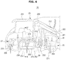
- FIGS. 5 and 6 are views illustrating a state in which a button of a suction portion according to one embodiment is operated.
- FIGS. 7 and 8 are views illustrating a state of an air hole according to an operation of a button according to one embodiment.
- FIGS. 9 and 10 are views illustrating a suction portion according to an operation of a button according to one embodiment.
- FIG. 11 is a bottom view of a frame according to another embodiment.
- FIG. 12 is a bottom view of a lower case according to another embodiment.
- FIGS. 13 and 14 are views illustrating a state in which a button of a suction portion according to another embodiment is operated.
- FIG. 15 is a view illustrating a frame and a lower case according to another embodiment.
- FIGS. 16 and 17 are views illustrating a state in which a button of a suction portion according to another embodiment is operated.
- FIG. 1 is a perspective view of a vacuum cleaner according to an embodiment.
- a vacuum cleaner 1 may be a canister type cleaner.
- the vacuum cleaner 1 may include a main body 10 , a dust collecting apparatus 101 installed in the main body 10 , and a suction portion 2 contacting a surface to be cleaned.
- the main body 10 may include a fan motor (not shown) for generating a suction force.
- the suction portion 2 may suck foreign materials on the surface to be cleaned by the suction force generated in the main body 10 .
- the suction portion 2 may be configured to be in close contact with the surface to be cleaned.
- the main body 10 may include a wheel 100 for driving the main body 10 .
- the wheel 100 may be disposed at both sides of the main body 10 .
- the wheel 100 may be movable in one direction.
- the body 10 may further include a caster (not shown) that is rotatable in all directions.
- the suction portion 2 may be connected to the main body 10 by an extension pipe 13 made of a resin or metal and a hose 11 which is flexible.
- a handle pipe 12 may be further provided between the extension pipe 13 and the hose 11 .
- the extension pipe 13 , the handle pipe 12 , and the hose 11 may communicate with each other. Air sucked through the suction portion 2 may pass through the extension pipe 13 , the handle pipe 12 and the hose 11 sequentially to enter the dust collecting apparatus 101 .
- the handle pipe 12 may include a controller 120 for controlling operations of the vacuum cleaner 1 .
- the controller 120 may include a plurality of buttons, a switch, a dial, and the like.
- the dust collecting apparatus 101 may be a cyclone dust collecting apparatus that generates a swirling airstream to separate foreign materials from air by a centrifugal force.
- the air from which foreign materials are separated in the dust collecting apparatus 101 may escape to the outside through a discharge port.
- the dust collecting apparatus 101 may be detachable from the main body 10 in order to throw away foreign materials collected therein.
- the suction portion 2 may be in contact with the surface to be cleaned so as to suck foreign materials on the surface to be cleaned together with air.
- the suction portion 2 may efficiently suck foreign materials on the surface to be cleaned with a high suction force.
- the suction portion 2 may suck foreign materials on the surface to be cleaned using the maximum of a suction force generated by the fan motor.
- the surface which the suction portion 2 is in contact with may be a hard surface or a carpet.
- a hard surface such as a floor
- the suction portion 2 may slide easily on the hard surface while being in contact with the hard surface. That is, a user may move the suction portion 2 with a small force even when the suction portion 2 is in close contact with the hard surface.
- the inside of the suction portion 2 may be hermetically sealed by a suction force when the suction portion 2 is in close contact with the carpet, so that the suction portion 2 may not easily slide on the carpet.
- the user may need to apply great strength to move the suction portion 2 when cleaning the carpet.
- a suction portion may be configured to make a predetermined gap with a surface to be cleaned in order to clean a surface to be cleaned, such as a carpet, while easily moving the suction portion 2 on the surface to be cleaned.
- a surface to be cleaned such as a carpet
- efficiency in cleaning a hard floor surface may be reduced.
- the present disclosure discloses a vacuum cleaner capable of adjusting a degree of contact between the suction portion 2 and a surface to be cleaned according to a state of the surface to be cleaned, thereby improving cleaning efficiency and improving mobility on the surface to be cleaned.
- FIG. 2 is a perspective view of a suction portion of a vacuum cleaner according to an embodiment
- FIG. 3 is a bottom view of a suction portion of a vacuum cleaner according to an embodiment
- FIG. 4 is an exploded perspective view of a suction portion of a vacuum cleaner according to an embodiment.
- the suction portion 2 may include a contact portion 20 contacting a surface to be cleaned, a connection pipe 21 connected to the extension pipe 13 (see FIG. 1 ), and a connection portion 22 connecting the contact portion 20 to the connection pipe 21 .
- the connection pipe 21 may be pivotally connected to the contact portion 20 to pivot in one direction or in a plurality of directions with respect to the contact portion 20 .
- connection pipe 21 may include a coupling portion 210 for connecting the connection pipe 21 to the extension pipe 13 .
- the connection pipe 21 may include a hook 211 for fixing the connection pipe 21 connected to the extension pipe 13 at a fixing portion (not shown) provided on the main body 10 .
- the connection portion 22 may include a wheel 220 for moving the contact portion 20 easily on the surface to be cleaned. When the contact portion 20 moves on the surface to be cleaned, the wheel 220 may travel on the surface to be cleaned. Two wheels 220 may be disposed at both the left and right sides of the connection portion 22 .
- connection portion 22 may include an inlet 222 that communicates with the connection pipe 21 . Foreign materials on the surface to be cleaned may be sucked through a suction port 200 formed in the contact portion 20 by suction force generated by the fan motor, flow into the inlet 222 , and then move to the dust collecting apparatus 101 through the connection pipe 21 , the extension pipe 13 , and the hose 11 .
- the inlet 222 may be connected to the connection pipe 21 by a flexible hose 221 .
- the inlet 222 may be connected to the connection pipe 21 by an accordion corrugated hose 221 . In this way, the inlet 222 may be pivotally connected to the connection pipe 21 by the flexible hose 221 .
- the contact portion 20 may include a button 23 for adjusting a degree of contact between the contact portion 20 and the surface to be cleaned.
- the user may operate the button 23 according to a state of a floor surface to open or close a plurality of air holes 256 formed in the contact portion 20 .
- the configuration of the button 23 will be described in detail, later.
- the contact portion 20 may include a lower case 25 , an upper case 26 , and a frame 27 .
- the frame 27 may be positioned between the upper case 26 and the lower case 25 .
- the frame 27 may move toward the upper case 26 or the lower case 25 by an operation of the button 23 .
- a hole 270 may be formed to communicate with the suction port 200 .
- a blade 272 may protrude to prevent a suction force of the fan motor from being lost.
- the blade 272 may extend toward the lower case 25 when the frame 27 is accommodated in space formed by the upper case 26 and the lower case 25 .
- the blade 272 may be disposed along an outer circumference of the frame 27 .
- two blades 272 may extend along both outer sides of the frame 27 , which are opposite to each other with the hole 270 in between. That is, a plurality of blades 272 may extend along the outer circumference of the frame 27 .
- a brush 271 may be disposed on one surface of the frame 27 .
- the brush 271 may extend in the same direction as the blade 272 . That is, when the frame 27 is accommodated in the space formed by the upper case 26 and the lower case 25 , the brush 271 may protrude toward the lower case 25 .
- the brush 271 may be disposed at an outer corner of the frame 27 .
- the brush 271 and the blade 272 may be positioned along the outer circumference of one surface of the frame 27 .
- the blade 272 may extend along the front (F) and rear (B) circumferences of the frame 27 .
- the brush 271 may be disposed at the corner of the front (F) or rear (B) portion of the frame 27 .
- the brush 271 and the blade 272 may have the same height from one surface of the frame 27 .
- the brush 271 and the blade 272 may be in close contact with the surface to be cleaned to minimize loss of a suction force between the surface to be cleaned and the contact portion 20 .
- the frame 27 may move in the upper case 26 and the lower case 25 to open or close the air holes 256 formed in the lower case 25 .
- the frame 27 may include a plurality of protrusions 273 for opening or closing the air holes 256 formed in the lower case 25 .
- the protrusions 273 may extend along the outer circumference of the frame 27 .
- the protrusions 273 may be disposed at the left (L) and right (R) sides of the surface of the frame 27 to correspond to the positions of the air holes 256 , respectively.
- the positions of the protrusions 273 and the air holes 256 are not limited to those described above.
- the lower case 25 may have the suction port 200 .
- the suction port 200 may be formed at a center of the lower case 25 .
- the lower case 25 may have a stepped portion extending in the left and right directions (L and R directions). More specifically, the lower case 25 may include a first surface 250 that is in contact with the surface to be cleaned, and a second surface 251 recessed upward from the first surface 250 .
- the suction port 200 may be positioned at a center of the second surface 251 .
- the second surface 251 may extend in the left and right directions (L and R directions) of the lower case 25 with respect to the moving directions of the contact portion 20 .
- a first insertion hole 254 and a second insertion hole 255 may be formed into which the brush 271 and the blade 272 provided in the frame 27 are inserted.
- the first insertion hole 254 may be formed at an outer corner of the first surface 250 to correspond to the brush 271 .
- the second insertion hole 255 may extend along the outer circumference in front-back direction of the first surface 250 to correspond to the blade 272 .
- the first surface 250 may include a cleaning portion 252 which is in contact with the surface to be cleaned.
- the cleaning portion 252 may be positioned in the front-rear direction of the lower case 25 with respect to the suction port 200 .
- the cleaning portion 252 may be a relatively short haired fabric.
- the hair of the cleaning portion 252 may extend in an oblique direction. In detail, the hair of the cleaning portion 252 located at the front portion of the lower case 25 may extend rearward, and the hair of the cleaning portion 252 located at the rear portion of the lower case 25 may extend forward.
- the cleaning portion 252 may be in contact with the surface to be cleaned, such as a carpet, and may capture foreign materials (for example, animal hair) which exist on the surface to be cleaned and are not easily detached from the surface to be cleaned, thereby easily detaching the foreign materials from the surface to be cleaned.
- the foreign materials detached from the surface to be cleaned may be sucked into the suction port 200 by a suction force of the fan motor.
- the second surface 251 may include a friction member 253 made of a flexible material such as rubber.
- the friction member 253 may be more or less longer than a length from the second surface 251 to the first surface 250 .
- the friction member 253 may rub against the carpet to raise foreign materials existing on the carpet. Then, the foreign materials may be easily sucked through the suction port 200 .
- the friction member 253 foreign materials existing on the carpet may be easily removed.
- the air holes 256 may be formed at one side of the lower case 25 .
- the air holes 256 may be formed on a flow path of the suction portion 2 .
- the air holes 256 may be formed at sides of the lower case 25 where the second surface 251 is located.
- the air holes 256 may be opened and closed by the frame 27 in accordance with an operation of the button 23 . More specifically, the air holes 256 may be opened or closed by the protrusions 273 provided in the frame 27 .
- inner space 262 in which the frame 27 is accommodated may be formed.
- An elastic member mounting portion 261 on which an elastic member 28 is mounted may be provided on the bottom of the upper case 26 .
- the elastic member mounting portion 261 may protrude from the bottom of the upper case 26 .
- the elastic member 28 may be mounted on the elastic member mounting portion 261 to provide an elastic force for pushing the frame 27 toward the upper case 26 .
- the button 23 may include pressing portions 231 and 232 that are pressed by a user.
- the pressing portions 231 and 232 may include a first pressing portion 231 and a second pressing portion 232 extending with a predetermined inclination from the first pressing portion 231 .
- the second pressing portion 232 may be integrated into the first pressing portion 231 .
- a plurality of interference ribs 233 may protrude from bottoms of the pressing portions 231 and 232 .
- a user may press the first pressing portion 231 or the second pressing portion 232 to move the frame 27 toward the upper case 26 or the lower case 25 .
- FIGS. 5 and 6 show states in which a button of a suction portion according to an embodiment is operated.
- the button 23 may include the pressing portions 231 and 232 and the interference ribs 233 protruding from the bottoms of the pressing portions 231 and 232 .
- the pressing portions 231 and 232 may include a first pressing portion 231 and a second pressing portion 232 bent from the first pressing portion 231 .
- the first pressing portion 231 and the second pressing portion 232 may be arranged in the front-rear direction.
- the first pressing portion 231 may be positioned in front of the second pressing portion 232 .
- a user may press the first pressing portion 231 or the second pressing portion 232 to move the frame 27 toward the upper case 26 or the lower case 25 depending on a state of the surface to be cleaned.
- the frame 27 may include sliding portions 274 and 275 having a bent shape.
- the interference ribs 233 may move along the sliding portions 274 and 275 provided in the frame 27 .
- the sliding portions 274 and 275 may include a first sliding portion 274 extending in one direction and a second sliding portion 275 bent downward in a diagonal direction from the first sliding portion 274 .
- the first sliding portion 274 may extend in the front-rear direction
- the second sliding portion 275 may extend toward the lower rear portion of the first sliding portion 274 .
- the interference ribs 233 may move along the sliding portions 274 and 275 provided in the frame 27 .
- a height h in vertical direction by which the interference ribs 233 move along the second sliding portion 275 may be equal to or more or less shorter than a length a 1 of the blade 272 provided in the frame 27 or a length a 2 of the brush 271 .
- the frame 27 may rise by the height h by which the interference ribs 233 are lowered, since the elastic member 28 provides an elastic force in a direction of pushing the frame 27 upward. Even when the force applied to the first pressing portion 231 is removed, the interference ribs 233 may be fixed so as not to move in a state of being positioned on the second sliding portion 275 . Thereby, the button 23 may maintain the pressed state of the first pressing portion 231 , and the frame 27 may move toward the upper case 26 .
- the blade 272 and the brush 271 mounted on the frame 27 may also move upward together with the frame 27 . More specifically, the blade 272 and the brush 271 may be inserted into the space formed by the upper case 26 and the lower case 25 .
- the ends of the interference ribs 233 may slide along the first sliding portion 274 via the second sliding portion 275 .
- the frame 27 may rise by the height h by which the interference ribs 233 has risen.
- the interference ribs 233 are positioned on the first sliding portion 274 , the frame 27 may move toward the lower case 25 .
- the interference ribs 233 may be fixed so as not to move on the first sliding portion 274 by an elastic force of the elastic member 28 .
- the button 23 may maintain the pressed state of the second pressing portion 232 .
- the blade 272 and the brush 271 mounted on the frame 27 may protrude to the bottom of the lower case 25 .
- FIGS. 7 and 8 show states of an air hole according to operations of a button according to an embodiment.
- the frame 27 when the first pressing portion 231 of the button 23 according to an embodiment is pressed, the frame 27 may move upward.
- the protrusions 273 provided on the frame 27 may also move upward, and the air holes 256 formed in the lower case 25 may open.
- the frame 27 When the second pressing portion 232 of the button 23 is pressed, the frame 27 may move downward. When the frame 27 moves downward, the protrusions 273 provided on the frame 27 may also move downward, and the air holes 256 may be closed by the protrusions 273 .
- FIGS. 9 and 10 show states of a suction portion according to operations of a button according to an embodiment.
- the user may press the first pressing portion 231 of the button 23 to open the air holes 256 .
- the frame 27 may move upward so that the blade 272 and the brush 271 are inserted into the inside space of the contact portion 20 .
- the first surface 250 of the lower case 25 may be in contact with the carpet which is the surface to be cleaned.
- FIG. 11 is a bottom view of a frame according to another embodiment.
- FIG. 12 is a bottom view of a lower case according to another embodiment.
- FIGS. 13 and 14 show states in which a button of a suction portion according to another embodiment is operated.
- An air hole 256 a may be formed at one side of the lower case 25 .
- the air hole 256 a may be formed on a flow path of the suction portion 2 .
- the air hole 256 a may be formed on an upper area of the flow path.
- the lower case 25 may include an extension surface 251 a extending downward from the second surface 251 , and a third surface 251 b extending in a horizontal direction from the extension surface 251 a .
- the third surface 251 b may be lower than the second surface 261 .
- a groove 257 may be formed by the third surface 251 b and the extension surface 251 a .
- a protrusion 273 a may be inserted into the groove 257 .
- the air hole 256 a may be formed in the third surface 251 b .
- the air hole 256 a may extend in the left and right directions (L and R directions), as shown in FIG. 12 .
- the frame 27 may include a protrusion 273 a for opening or closing the air hole 256 a formed in the lower case 25 .
- the protrusion 273 a may be formed on the flow path of the suction portion 2 to correspond to the position of the air hole 256 a .
- the protrusion 273 a may be provided in the upper area of the flow path.
- the protrusion 273 a may be provided at both sides of the hole 270 of the frame 27 .
- the protrusion 273 a may be disposed in parallel to the blade 272 .
- the protrusion 273 a may be provided at the left and right portions of one surface of the frame 27 respectively to correspond to the position of the air hole 256 a.
- the protrusion 273 a may protrude downward from the surface of the frame 27 .
- the protrusion 273 a may move up and down according to an operation of the button 23 .
- the protrusion 273 a may be inserted into the groove 257 to close the air hole 256 a .
- the protrusion 273 a may escape from the groove 257 to open the air hole 256 a.
- a button 23 may include pressing portions 231 and 232 and interference ribs 233 protruding from bottoms of the pressing portions 231 and 232 .
- the pressing portions 231 and 232 may include a first pressing portion 231 , and a second pressing portion 232 bent from the first pressing portion 231 .
- the first pressing portion 231 and the second pressing portion 232 may be arranged in the front-rear direction.
- the first pressing portion 231 may be positioned in front of the second pressing portion 232 .
- the user may press the first pressing portion 231 or the second pressing portion 232 to move the frame 27 toward the upper case 26 or the lower case 25 depending on a state of a surface to be cleaned.
- the frame 27 may include sliding portions 274 and 275 having a bent shape.
- the interference rib 233 may move along the sliding portions 274 and 275 provided on the frame 27 .
- the sliding portions 274 and 275 may include a first sliding portion 274 extending in one direction, and a second sliding portion 275 bent downward in a diagonal direction from the first sliding portion 274 .
- the first sliding portion 274 may extend in the front-rear direction
- the second sliding portion 275 may extend toward the lower rear portion of the first sliding portion 274 .
- the interference ribs 233 may move along the sliding portions 274 and 275 provided on the frame 27 .
- a height h in vertical direction by which the interference ribs 233 move along the second sliding portion 275 may be equal to or more or less shorter than the length a 1 of the blade 272 provided in the frame 27 or the length a 2 of the brush 271 .
- the frame 27 may rise by the height h by which the interference rib 233 is lowered, since the elastic member 28 provides an elastic force in a direction of pushing the frame 27 upward. Even when the force applied to the first pressing portion 231 is removed, the interference rib 233 may be fixed not to move in a state of being positioned on the second sliding portion 275 . Thereby, the button 23 may maintain the pressed state of the first pressing portion 231 , and the frame 27 may move toward the upper case 26 .
- the blade 272 and the brush 271 mounted on the frame 27 may move upward together with the frame 27 .
- the blade 272 and the brush 271 may be inserted into the space formed by the upper case 26 and the lower case 25 .
- the ends of the interference ribs 233 may slide along the first sliding portion 274 via the second sliding portion 275 .
- the frame 27 may rise by the height h by which the interference ribs 233 rise.
- the interference ribs 233 are positioned on the first sliding portion 274 , the frame 27 may move toward the lower case 25 .
- the interference ribs 233 may be fixed not to move on the first sliding portion 274 by the elastic force of the elastic member 28 .
- the button 23 may maintain the pressed state of the second pressing portion 232 .
- the blade 272 and the brush 271 mounted on the frame 27 may protrude to the bottom of the lower case 25 .
- the frame 27 When the first pressing portion 231 of the button 23 is pressed, the frame 27 may move upward. When the frame 27 moves upward, the protrusion 273 a provided on the frame 27 may also move upward, and the air hole 256 a formed in the lower case 25 may open.
- the frame 27 When the second pressing portion 232 of the button 23 is pressed, the frame 27 may move downward. When the frame 27 moves downward, the protrusion 273 a provided on the frame 27 may also move downward, and the air hole 256 a may be closed by the protrusion 273 a.
- the user may press the first pressing portion 231 of the button 23 to open the air hole 256 a .
- the frame 27 may move upward so that the blade 272 and the brush 271 are inserted into the inside space of the contact portion 20 .
- the first surface 250 of the lower case 25 may be in contact with the carpet which is the surface to be cleaned.
- FIG. 15 shows a frame and a lower case according to another embodiment.
- FIGS. 16 and 17 show states in which a button of a suction portion according to another embodiment is operated.
- the frame 27 may include a hole 270 that communicates with the suction port 200 .
- the frame 27 may also include an air hole opening and closing member 280 .
- the air hole opening and closing member 280 may be mounted on the front portion of the frame 27 .
- the air hole opening and closing member 280 may be integrated into the frame 27 .
- the air hole opening and closing member 280 may include a protrusion 281 for opening and closing the air hole 256 b .
- the protrusion 281 may be formed on one side of the air hole opening and closing member 280 .
- the protrusion 281 may be formed at a position corresponding to the air hole 256 b .
- the protrusion 281 may open or close the air hole 256 b according to an operation of the button 23 .
- the lower case 25 may include a flowpath forming portion 290 disposed above the suction port 200 .
- the flowpath forming portion 290 may connect the suction port 200 and the inlet 222 .
- Mounting portions 291 and 292 may be provided at both sides of the flowpath forming portion 290 .
- the lower case 25 may include boss portions 293 and 294 provided at both sides of the suction port 200 .
- the mounting portions 291 and 292 may be coupled with the boss portions 293 and 294 by fastening members 295 and 296 . Thereby, the flowpath forming portion 290 may be fixed at the lower case 25 .
- An air hole 256 b may be formed at one side of the flowpath forming portion 290 .
- the air hole 256 b may be formed on the flowpath of the suction unit 2 .
- the air hole 256 b may be formed in the upper surface of the flowpath forming portion 290 .
- the frame 27 may move up and down by a user. As in the other embodiments, when the first pressing portion 231 of the button 23 is pressed, the frame 27 may move upward. When the frame 27 moves upward, the protrusion 281 formed in the frame 27 may also move upward, and the air hole 256 b formed in the lower case 25 may open.
- the frame 27 When the second pressing portion 232 of the button 23 is pressed, the frame 27 may move downward. When the frame 27 moves downward, the protrusion 281 formed in the frame 27 may also move downward, and the air hole 256 b may be closed by the protrusion 281 .
- the user may press the first pressing portion 231 of the button 23 to open the air hole 256 b .
- the frame 27 may move upward so that the blade 272 and the brush 271 are inserted into the inside space of the contact portion 20 .
- the first surface 250 of the lower case 25 may be in contact with the carpet which is the surface to be cleaned.
- the suction portion and the surface to be cleaned may form sealed space, which makes it difficult to move the suction portion. That is, a user may need to apply great strength to move the suction portion on a surface to be cleaned.
- the air holes 256 , 256 a , and 256 b provided at one side of the contact portion 20 may open to prevent the space formed by the surface to be cleaned and the contact portion 20 from being sealed. Accordingly, the user may clean the carpet with a small force by moving the contact portion 20 easily on the carpet.
- the friction member 253 provided on the second surface 251 of the lower case 25 may rub against the carpet to raise foreign materials existing on the carpet.
- the fan motor When the fan motor generates a suction force, foreign materials and air may be sucked in and introduced to the inlet 222 and move to the dust collecting apparatus 101 through the connection pipe 21 , the extension pipe 13 and the hose 11 .
- the user may press the second pressing portion 232 of the button 23 to close the air holes 256 , 256 a , and 256 b .
- the surface to be cleaned is a hard surface such as a floor and the air holes 256 , 256 a , and 256 b open, the suction force generated by the fan motor may be lost. Therefore, when the surface to be cleaned is a hard surface, the user may close the air holes 256 , 256 a , and 256 b to prevent the loss of the suction force.
- the frame 27 may move downward, and the brush 271 and the blade 272 provided in the frame 27 may protrude from the bottom of the lower case 25 .
- the brush 271 may sweep the surface to be surface.
- the blade 272 may seal the space between the lower case 25 and the surface to be cleaned, in order to prevent the loss of the suction force of the fan motor by the protruding brush 271 .
- the air holes 256 , 256 a , and 256 b may be closed, thereby preventing degradation of cleaning efficiency.
- the vacuum cleaner 1 may open or close the air holes 256 , 256 a , and 256 b provided in the suction portion 2 according to a state of a surface to be cleaned.
- the vacuum cleaner 1 may open the air holes 256 , 256 a and 256 b to improve the mobility of the suction portion 2 .
- the vacuum cleaner 1 may close the air holes 256 , 256 a , and 256 b to prevent the suction force of the fan motor from being lost.
- the vacuum cleaner 1 may prevent degradation of cleaning efficiency, and improve usability.
Landscapes
- Engineering & Computer Science (AREA)
- Mechanical Engineering (AREA)
- Nozzles For Electric Vacuum Cleaners (AREA)
Abstract
Description
Claims (20)
Applications Claiming Priority (3)
| Application Number | Priority Date | Filing Date | Title |
|---|---|---|---|
| KR10-2016-0052231 | 2016-04-28 | ||
| KR1020160052231A KR20170123059A (en) | 2016-04-28 | 2016-04-28 | Vacuum cleaner |
| PCT/KR2017/004098 WO2017188638A1 (en) | 2016-04-28 | 2017-04-17 | Vacuum cleaner |
Publications (2)
| Publication Number | Publication Date |
|---|---|
| US20190104901A1 US20190104901A1 (en) | 2019-04-11 |
| US11076732B2 true US11076732B2 (en) | 2021-08-03 |
Family
ID=60160924
Family Applications (1)
| Application Number | Title | Priority Date | Filing Date |
|---|---|---|---|
| US16/097,118 Active 2038-03-28 US11076732B2 (en) | 2016-04-28 | 2017-04-17 | Vacuum cleaner |
Country Status (4)
| Country | Link |
|---|---|
| US (1) | US11076732B2 (en) |
| EP (1) | EP3434165B1 (en) |
| KR (1) | KR20170123059A (en) |
| WO (1) | WO2017188638A1 (en) |
Families Citing this family (2)
| Publication number | Priority date | Publication date | Assignee | Title |
|---|---|---|---|---|
| GB201603300D0 (en) * | 2016-02-25 | 2016-04-13 | Grey Technology Ltd | Suction head for a vacuum cleaner |
| KR102904609B1 (en) * | 2020-02-18 | 2025-12-29 | 엘지전자 주식회사 | A cleaner and control method thereof |
Citations (9)
| Publication number | Priority date | Publication date | Assignee | Title |
|---|---|---|---|---|
| US5539953A (en) | 1992-01-22 | 1996-07-30 | Kurz; Gerhard | Floor nozzle for vacuum cleaners |
| KR19990038283A (en) | 1997-11-04 | 1999-06-05 | 구자홍 | Suction port of vacuum cleaner |
| GB2432301A (en) | 2005-11-21 | 2007-05-23 | Sharp Kk | Vacuum cleaner |
| KR20080104504A (en) | 2007-05-28 | 2008-12-03 | 삼성광주전자 주식회사 | Suction brush for vacuum cleaner |
| US7552507B2 (en) * | 2006-09-09 | 2009-06-30 | Vax Limited | Cleaning head for a vacuum cleaner |
| EP2098150A2 (en) | 2008-03-06 | 2009-09-09 | Wessel-Werk Gmbh | Nozzle for floor vacuum cleaner |
| US20140096340A1 (en) | 2012-10-04 | 2014-04-10 | Samsung Electronics Co., Ltd. | Vacuum cleaner |
| EP2875765A1 (en) | 2013-11-21 | 2015-05-27 | BSH Hausgeräte GmbH | Suction nozzle for a vacuum cleaner |
| US20160113458A1 (en) * | 2014-10-27 | 2016-04-28 | Conet Industries, Inc. | Cleaning nozzle assembly |
-
2016
- 2016-04-28 KR KR1020160052231A patent/KR20170123059A/en not_active Ceased
-
2017
- 2017-04-17 US US16/097,118 patent/US11076732B2/en active Active
- 2017-04-17 WO PCT/KR2017/004098 patent/WO2017188638A1/en not_active Ceased
- 2017-04-17 EP EP17789823.6A patent/EP3434165B1/en active Active
Patent Citations (11)
| Publication number | Priority date | Publication date | Assignee | Title |
|---|---|---|---|---|
| US5539953A (en) | 1992-01-22 | 1996-07-30 | Kurz; Gerhard | Floor nozzle for vacuum cleaners |
| KR100244348B1 (en) | 1992-01-22 | 2000-04-01 | 게르하르트쿠르츠 | Floor nozzle for vacuum cleaner |
| KR19990038283A (en) | 1997-11-04 | 1999-06-05 | 구자홍 | Suction port of vacuum cleaner |
| GB2432301A (en) | 2005-11-21 | 2007-05-23 | Sharp Kk | Vacuum cleaner |
| US7552507B2 (en) * | 2006-09-09 | 2009-06-30 | Vax Limited | Cleaning head for a vacuum cleaner |
| KR20080104504A (en) | 2007-05-28 | 2008-12-03 | 삼성광주전자 주식회사 | Suction brush for vacuum cleaner |
| US20080295270A1 (en) | 2007-05-28 | 2008-12-04 | Samsung Gwangju Electronics Co., Ltd. | Suction brush for vacuum cleaner |
| EP2098150A2 (en) | 2008-03-06 | 2009-09-09 | Wessel-Werk Gmbh | Nozzle for floor vacuum cleaner |
| US20140096340A1 (en) | 2012-10-04 | 2014-04-10 | Samsung Electronics Co., Ltd. | Vacuum cleaner |
| EP2875765A1 (en) | 2013-11-21 | 2015-05-27 | BSH Hausgeräte GmbH | Suction nozzle for a vacuum cleaner |
| US20160113458A1 (en) * | 2014-10-27 | 2016-04-28 | Conet Industries, Inc. | Cleaning nozzle assembly |
Non-Patent Citations (3)
| Title |
|---|
| European Patent Office, "Supplementary European Search Report," Application No. EP17789823.6, dated Mar. 14, 2019, 7 pages. |
| International Search Report dated Jul. 27, 2017 in connection with International Patent Application No. PCT/KR2017/004098. |
| Written Opinion of the International Searching Authority dated Jul. 27, 2017 in connection with International Patent Application No. PCT/KR2017/004098. |
Also Published As
| Publication number | Publication date |
|---|---|
| EP3434165B1 (en) | 2022-09-14 |
| WO2017188638A1 (en) | 2017-11-02 |
| US20190104901A1 (en) | 2019-04-11 |
| KR20170123059A (en) | 2017-11-07 |
| EP3434165A4 (en) | 2019-04-17 |
| EP3434165A1 (en) | 2019-01-30 |
Similar Documents
| Publication | Publication Date | Title |
|---|---|---|
| KR102620360B1 (en) | Robot cleaner, station and cleaning system | |
| KR102793630B1 (en) | Robot cleaner station | |
| EP1733670B1 (en) | Improvements in vacuum cleaners | |
| US7325274B2 (en) | Vacuum cleaner with dust collecting device | |
| KR102376142B1 (en) | Vacuum cleaner | |
| GB2403132A (en) | Tilting vacuum cleaner with removable body portion | |
| US10799080B2 (en) | Cleaner | |
| EP3412187B1 (en) | Cleaner | |
| US5826299A (en) | Brush assembly for a vacuum cleaner | |
| US7231687B2 (en) | Vacuum cleaner with flow channel switch for blowing and sucking air | |
| US20170086631A1 (en) | Vacuum cleaner | |
| US11076732B2 (en) | Vacuum cleaner | |
| CN111818831A (en) | cleaner head | |
| US11197594B2 (en) | Cleaner | |
| US9999329B2 (en) | Aspiration nozzle of vacuum cleaner and vacuum cleaner having same | |
| KR102328244B1 (en) | Cleaner | |
| KR101192465B1 (en) | Robot cleaner | |
| WO2019166761A1 (en) | A cleaner head | |
| JPH10192200A (en) | Electric vacuum cleaner | |
| US11786090B2 (en) | Floor nozzle for a vacuum cleaner and vacuum cleaner | |
| JP2009078081A (en) | Vacuum cleaner and its suction port | |
| KR20160028328A (en) | Vacuum cleaner | |
| KR20220132273A (en) | vacuum cleaner | |
| JP3542286B2 (en) | Suction port body and vacuum cleaner | |
| JP2017018413A (en) | Electric vacuum cleaner |
Legal Events
| Date | Code | Title | Description |
|---|---|---|---|
| AS | Assignment |
Owner name: SAMSUNG ELECTRONICS CO., LTD., KOREA, REPUBLIC OF Free format text: ASSIGNMENT OF ASSIGNORS INTEREST;ASSIGNORS:YANG, DONG HOUN;KIM, HYEON CHEOL;PARK, JOUNG SOO;AND OTHERS;REEL/FRAME:047330/0572 Effective date: 20181025 |
|
| FEPP | Fee payment procedure |
Free format text: ENTITY STATUS SET TO UNDISCOUNTED (ORIGINAL EVENT CODE: BIG.); ENTITY STATUS OF PATENT OWNER: LARGE ENTITY |
|
| STPP | Information on status: patent application and granting procedure in general |
Free format text: DOCKETED NEW CASE - READY FOR EXAMINATION |
|
| STPP | Information on status: patent application and granting procedure in general |
Free format text: NON FINAL ACTION MAILED |
|
| STPP | Information on status: patent application and granting procedure in general |
Free format text: RESPONSE TO NON-FINAL OFFICE ACTION ENTERED AND FORWARDED TO EXAMINER |
|
| STPP | Information on status: patent application and granting procedure in general |
Free format text: NOTICE OF ALLOWANCE MAILED -- APPLICATION RECEIVED IN OFFICE OF PUBLICATIONS |
|
| STPP | Information on status: patent application and granting procedure in general |
Free format text: PUBLICATIONS -- ISSUE FEE PAYMENT RECEIVED |
|
| STPP | Information on status: patent application and granting procedure in general |
Free format text: PUBLICATIONS -- ISSUE FEE PAYMENT VERIFIED |
|
| STCF | Information on status: patent grant |
Free format text: PATENTED CASE |
|
| MAFP | Maintenance fee payment |
Free format text: PAYMENT OF MAINTENANCE FEE, 4TH YEAR, LARGE ENTITY (ORIGINAL EVENT CODE: M1551); ENTITY STATUS OF PATENT OWNER: LARGE ENTITY Year of fee payment: 4 |