US11075433B2 - Rechargeable battery including an overcharge safety device - Google Patents
Rechargeable battery including an overcharge safety device Download PDFInfo
- Publication number
- US11075433B2 US11075433B2 US16/343,674 US201716343674A US11075433B2 US 11075433 B2 US11075433 B2 US 11075433B2 US 201716343674 A US201716343674 A US 201716343674A US 11075433 B2 US11075433 B2 US 11075433B2
- Authority
- US
- United States
- Prior art keywords
- free end
- electrode
- short
- rechargeable battery
- electrode terminal
- Prior art date
- Legal status (The legal status is an assumption and is not a legal conclusion. Google has not performed a legal analysis and makes no representation as to the accuracy of the status listed.)
- Active, expires
Links
Images


Classifications
-
- H—ELECTRICITY
- H01—ELECTRIC ELEMENTS
- H01M—PROCESSES OR MEANS, e.g. BATTERIES, FOR THE DIRECT CONVERSION OF CHEMICAL ENERGY INTO ELECTRICAL ENERGY
- H01M50/00—Constructional details or processes of manufacture of the non-active parts of electrochemical cells other than fuel cells, e.g. hybrid cells
- H01M50/50—Current conducting connections for cells or batteries
- H01M50/572—Means for preventing undesired use or discharge
-
- H—ELECTRICITY
- H01—ELECTRIC ELEMENTS
- H01M—PROCESSES OR MEANS, e.g. BATTERIES, FOR THE DIRECT CONVERSION OF CHEMICAL ENERGY INTO ELECTRICAL ENERGY
- H01M10/00—Secondary cells; Manufacture thereof
- H01M10/04—Construction or manufacture in general
-
- H—ELECTRICITY
- H01—ELECTRIC ELEMENTS
- H01M—PROCESSES OR MEANS, e.g. BATTERIES, FOR THE DIRECT CONVERSION OF CHEMICAL ENERGY INTO ELECTRICAL ENERGY
- H01M10/00—Secondary cells; Manufacture thereof
- H01M10/04—Construction or manufacture in general
- H01M10/0431—Cells with wound or folded electrodes
-
- H—ELECTRICITY
- H01—ELECTRIC ELEMENTS
- H01M—PROCESSES OR MEANS, e.g. BATTERIES, FOR THE DIRECT CONVERSION OF CHEMICAL ENERGY INTO ELECTRICAL ENERGY
- H01M50/00—Constructional details or processes of manufacture of the non-active parts of electrochemical cells other than fuel cells, e.g. hybrid cells
- H01M50/10—Primary casings; Jackets or wrappings
- H01M50/147—Lids or covers
- H01M50/148—Lids or covers characterised by their shape
- H01M50/15—Lids or covers characterised by their shape for prismatic or rectangular cells
-
- H—ELECTRICITY
- H01—ELECTRIC ELEMENTS
- H01M—PROCESSES OR MEANS, e.g. BATTERIES, FOR THE DIRECT CONVERSION OF CHEMICAL ENERGY INTO ELECTRICAL ENERGY
- H01M50/00—Constructional details or processes of manufacture of the non-active parts of electrochemical cells other than fuel cells, e.g. hybrid cells
- H01M50/10—Primary casings; Jackets or wrappings
- H01M50/147—Lids or covers
- H01M50/166—Lids or covers characterised by the methods of assembling casings with lids
- H01M50/169—Lids or covers characterised by the methods of assembling casings with lids by welding, brazing or soldering
-
- H—ELECTRICITY
- H01—ELECTRIC ELEMENTS
- H01M—PROCESSES OR MEANS, e.g. BATTERIES, FOR THE DIRECT CONVERSION OF CHEMICAL ENERGY INTO ELECTRICAL ENERGY
- H01M50/00—Constructional details or processes of manufacture of the non-active parts of electrochemical cells other than fuel cells, e.g. hybrid cells
- H01M50/10—Primary casings; Jackets or wrappings
- H01M50/172—Arrangements of electric connectors penetrating the casing
- H01M50/174—Arrangements of electric connectors penetrating the casing adapted for the shape of the cells
- H01M50/176—Arrangements of electric connectors penetrating the casing adapted for the shape of the cells for prismatic or rectangular cells
-
- H—ELECTRICITY
- H01—ELECTRIC ELEMENTS
- H01M—PROCESSES OR MEANS, e.g. BATTERIES, FOR THE DIRECT CONVERSION OF CHEMICAL ENERGY INTO ELECTRICAL ENERGY
- H01M50/00—Constructional details or processes of manufacture of the non-active parts of electrochemical cells other than fuel cells, e.g. hybrid cells
- H01M50/50—Current conducting connections for cells or batteries
- H01M50/543—Terminals
- H01M50/547—Terminals characterised by the disposition of the terminals on the cells
- H01M50/55—Terminals characterised by the disposition of the terminals on the cells on the same side of the cell
-
- H—ELECTRICITY
- H01—ELECTRIC ELEMENTS
- H01M—PROCESSES OR MEANS, e.g. BATTERIES, FOR THE DIRECT CONVERSION OF CHEMICAL ENERGY INTO ELECTRICAL ENERGY
- H01M50/00—Constructional details or processes of manufacture of the non-active parts of electrochemical cells other than fuel cells, e.g. hybrid cells
- H01M50/50—Current conducting connections for cells or batteries
- H01M50/543—Terminals
- H01M50/552—Terminals characterised by their shape
- H01M50/553—Terminals adapted for prismatic, pouch or rectangular cells
-
- H—ELECTRICITY
- H01—ELECTRIC ELEMENTS
- H01M—PROCESSES OR MEANS, e.g. BATTERIES, FOR THE DIRECT CONVERSION OF CHEMICAL ENERGY INTO ELECTRICAL ENERGY
- H01M50/00—Constructional details or processes of manufacture of the non-active parts of electrochemical cells other than fuel cells, e.g. hybrid cells
- H01M50/50—Current conducting connections for cells or batteries
- H01M50/572—Means for preventing undesired use or discharge
- H01M50/574—Devices or arrangements for the interruption of current
- H01M50/578—Devices or arrangements for the interruption of current in response to pressure
-
- H—ELECTRICITY
- H01—ELECTRIC ELEMENTS
- H01M—PROCESSES OR MEANS, e.g. BATTERIES, FOR THE DIRECT CONVERSION OF CHEMICAL ENERGY INTO ELECTRICAL ENERGY
- H01M50/00—Constructional details or processes of manufacture of the non-active parts of electrochemical cells other than fuel cells, e.g. hybrid cells
- H01M50/50—Current conducting connections for cells or batteries
- H01M50/572—Means for preventing undesired use or discharge
- H01M50/574—Devices or arrangements for the interruption of current
- H01M50/581—Devices or arrangements for the interruption of current in response to temperature
-
- H—ELECTRICITY
- H01—ELECTRIC ELEMENTS
- H01M—PROCESSES OR MEANS, e.g. BATTERIES, FOR THE DIRECT CONVERSION OF CHEMICAL ENERGY INTO ELECTRICAL ENERGY
- H01M50/00—Constructional details or processes of manufacture of the non-active parts of electrochemical cells other than fuel cells, e.g. hybrid cells
- H01M50/50—Current conducting connections for cells or batteries
- H01M50/572—Means for preventing undesired use or discharge
- H01M50/574—Devices or arrangements for the interruption of current
- H01M50/583—Devices or arrangements for the interruption of current in response to current, e.g. fuses
-
- H—ELECTRICITY
- H01—ELECTRIC ELEMENTS
- H01M—PROCESSES OR MEANS, e.g. BATTERIES, FOR THE DIRECT CONVERSION OF CHEMICAL ENERGY INTO ELECTRICAL ENERGY
- H01M2200/00—Safety devices for primary or secondary batteries
- H01M2200/10—Temperature sensitive devices
-
- H—ELECTRICITY
- H01—ELECTRIC ELEMENTS
- H01M—PROCESSES OR MEANS, e.g. BATTERIES, FOR THE DIRECT CONVERSION OF CHEMICAL ENERGY INTO ELECTRICAL ENERGY
- H01M2200/00—Safety devices for primary or secondary batteries
- H01M2200/10—Temperature sensitive devices
- H01M2200/103—Fuse
-
- H—ELECTRICITY
- H01—ELECTRIC ELEMENTS
- H01M—PROCESSES OR MEANS, e.g. BATTERIES, FOR THE DIRECT CONVERSION OF CHEMICAL ENERGY INTO ELECTRICAL ENERGY
- H01M2200/00—Safety devices for primary or secondary batteries
- H01M2200/20—Pressure-sensitive devices
-
- Y—GENERAL TAGGING OF NEW TECHNOLOGICAL DEVELOPMENTS; GENERAL TAGGING OF CROSS-SECTIONAL TECHNOLOGIES SPANNING OVER SEVERAL SECTIONS OF THE IPC; TECHNICAL SUBJECTS COVERED BY FORMER USPC CROSS-REFERENCE ART COLLECTIONS [XRACs] AND DIGESTS
- Y02—TECHNOLOGIES OR APPLICATIONS FOR MITIGATION OR ADAPTATION AGAINST CLIMATE CHANGE
- Y02E—REDUCTION OF GREENHOUSE GAS [GHG] EMISSIONS, RELATED TO ENERGY GENERATION, TRANSMISSION OR DISTRIBUTION
- Y02E60/00—Enabling technologies; Technologies with a potential or indirect contribution to GHG emissions mitigation
- Y02E60/10—Energy storage using batteries
-
- Y—GENERAL TAGGING OF NEW TECHNOLOGICAL DEVELOPMENTS; GENERAL TAGGING OF CROSS-SECTIONAL TECHNOLOGIES SPANNING OVER SEVERAL SECTIONS OF THE IPC; TECHNICAL SUBJECTS COVERED BY FORMER USPC CROSS-REFERENCE ART COLLECTIONS [XRACs] AND DIGESTS
- Y02—TECHNOLOGIES OR APPLICATIONS FOR MITIGATION OR ADAPTATION AGAINST CLIMATE CHANGE
- Y02P—CLIMATE CHANGE MITIGATION TECHNOLOGIES IN THE PRODUCTION OR PROCESSING OF GOODS
- Y02P70/00—Climate change mitigation technologies in the production process for final industrial or consumer products
- Y02P70/50—Manufacturing or production processes characterised by the final manufactured product
Definitions
- the present invention relates to a rechargeable battery. More particularly, the present invention relates to a rechargeable battery in which an overcharge safety device is activated in an overcharge state in an internal space of a cell.
- a rechargeable battery is a battery that repeatedly performs charging and discharging, differently from a primary battery.
- a rechargeable battery with small capacity is used in a small portable electronic device, such as a mobile phone, a notebook computer, and a camcorder, and a rechargeable battery with large capacity may be used as a motor driving power source for a hybrid vehicle and an electric vehicle.
- rechargeable batteries include an electrode assembly for charging and discharging, a case accommodating the electrode assembly and an electrolyte solution, a cap plate coupled to the opening of the case, and an electrode terminal that electrically connects the electrode assembly to draw out the electrode assembly to the outside of the cap plate.
- the rechargeable battery includes an overcharge safety device for overcharge control.
- the overcharge safety device includes a short-circuit tab and a short-circuit member that is separated or short-circuited according to an internal pressure.
- the short-circuit tab is electrically connected to a negative electrode, and the short-circuit member is electrically connected to a positive electrode.
- the short-circuit member When a cell is overcharged, the short-circuit member is inverted and thus contacts the short-circuit tab, thereby causing discharge of a current charged in the electrode assembly.
- an inversion shape of the short-circuit member may not be constant. Accordingly, contact area scatter occurs from a contact surface of the short-circuit member and the short-circuit tab, thereby causing generation of resistance scatter from the contact surface. That is, the overcharge safety device cannot effectively control overcharge of the rechargeable battery, thereby generating quality scatter.
- An exemplary embodiment of the present invention has been made in an effort to provide a rechargeable battery that can block a current of a cell without causing quality scatter by removing operating scatter of the overcharge safety device upon occurrence of overcharge in the cell.
- an exemplary embodiment of the present invention provides a rechargeable battery that includes an overcharge safety device that is not influenced by a cell manufacturing process and does not cause operating scatter.
- An overcharge safety device includes: an electrode assembly in which a first electrode and a second electrode are disposed at opposite sides of a separator; a case in which the electrode assembly is accommodated; a cap plate that is combined to an opening of the case; a first electrode terminal and a second electrode terminal that are provided in terminal holes of the cap plate and respectively connected to the first electrode and the second electrode; and an overcharge safety device in which a first free end and a second free end of a first short-circuit member and a second short-circuit member that are respectively connected to the first electrode terminal and the second electrode terminal in the cap plane are disposed apart from each other and received in a tube.
- the overcharge safety device may further include holders that seal a first fixing portion and a second fixing portion at predetermined locations from the first free end and the second free end in the first short-circuit member and the second short-circuit member that are combined to opposite ends of the tube and extend to the inside of the tube.
- the tube may be provided as a compression tube that contracts by an internal pressure increase due to a gas generated from an internal space set by the cap plate and the case upon overcharge such that the first free end and the second free end contact each other.
- the tube may be provided as a heat-shrink tube that contracts by an internal heat increase generated from an internal space set by the cap plate and the case upon overcharge such that the first free end and the second free end contact each other.
- the tube may be provided as a compression/heat-shrink tube that contracts by an internal pressure increase and an internal heat increase due to a gas generated from an internal space set by the cap plate and the case upon overcharge such that the first free end and the second free end contact each other.
- the first short-circuit member and the second short-circuit member may extend to a predetermined length with a width and a thickness.
- the first short-circuit member and the second short-circuit member may be bent between the holder and the first electrode terminal and between the holder and the second electrode terminal, and may be connected to the first electrode terminal and the second electrode terminal through a wide area of a first connection end portion and a wide area of a second connection end portion.
- the first free end and the second free end may be disposed opposing each other at a distance from each other in a direction that crosses a plane of the cap plate in the case, and the first connection end portion and the second connection end portion may be connected with the first electrode terminal and the second electrode terminal in a surface-contact manner in a width direction of the cap plate in the case.
- first free end and the second free end that are activated upon overcharge and surface-contact each other may have the same width as a fixing width of the first fixing portion and a fixing width of the second fixing portion that are fixed to the holders.
- the first free end and the second free end that are activated upon overcharge and surface-contact each other may have a first width W 1 that is larger than a second width W 2 of the first fixing portion and the second fixing portion fixed to the holders.
- the first free end and the second free end may surface-contact each other with an area having a predetermined length and the first width.
- the first fixing portion and the second fixing portion may be fixed to the holders with the second width.
- the first free end and the second free end may curve-contact each other with an area having a predetermined length and the first width.
- the first fixing portion and the second fixing portion may be connected as planes to the first free end and the second free end, which are curved, and fixed to the holders with the second width.
- the second electrode terminal may be connected to an uncoated region tab of the second electrode through an inner side end thereof and is connected to the second short-circuit member at an upper portion of the uncoated region tab, and the second electrode terminal may further include a fuse that is formed between the uncoated region tab and the second short-circuit member.
- the overcharge safety device formed inside the tube that contacts the first short-circuit member and the second short-circuit member which are separated from each other is provided inside the cap plate, operating scatter of the overcharge safety device can be removed and a current of a cell can be blocked without quality scatter upon overcharge.
- the overcharge safety device can be separately manufactured from the cell and is connected with the first and second electrode terminals inside the cap plate, and thus the device is not influenced by a manufacturing process of the cell, and a current of the cell can be blocked without causing operating scatter upon overcharge.
- FIG. 1 is a perspective view of a rechargeable battery according to a first exemplary embodiment of the present invention.
- FIG. 2 is a cross-sectional view of FIG. 1 , taken along the line II-II.
- FIG. 3 is a cross-sectional view of FIG. 1 , taken along the line III-III.
- FIG. 4 is a perspective view of an electrode assembly applied to FIG. 3 .
- FIG. 5 is a perspective view in a state that an electrode terminal and an overcharge safety device are connected to the electrode assembly of FIG. 4 .
- FIG. 6 is a perspective view of an overcharge safety device applied to FIG. 5 .
- FIG. 7 is an exploded perspective view of the overcharge safety device of FIG. 6 .
- FIG. 8 is a cross-sectional view of FIG. 6 , taken along the line VIII-VIII.
- FIG. 9 is a cross-sectional view of an overcharge safety device of FIG. 8 , in an activated state.
- FIG. 10 is a cross-sectional view of FIG. 9 , taken along the line X-X.
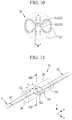
- FIG. 11 is a perspective view of an overcharge safety device applied to a rechargeable battery according to a second exemplary embodiment.
- FIG. 12 is an exploded perspective view of the overcharge safety device of FIG. 11 .
- FIG. 13 is a cross-sectional view of FIG. 11 , taken along the line XIII-XIII.
- FIG. 14 is a perspective view of an overcharge safety device applied to a rechargeable battery according to a third exemplary embodiment of the present invention.
- FIG. 15 is an exploded perspective view of the overcharge safety device of FIG. 14 .
- FIG. 16 is a cross-sectional view of FIG. 14 , taken along the line XVI-XVI.
- FIG. 1 is a perspective view of a rechargeable battery according to a first exemplary embodiment of the present invention
- FIG. 2 is a cross-sectional view of FIG. 1 , taken along the line II-II
- FIG. 3 is a cross-sectional view of FIG. 1 , taken along the line III-IIII.
- a rechargeable battery includes an electrode assembly 10 that charges and discharges a current, a case 30 in which the electrode assembly 10 and an electrolyte solution are embedded, a cap plate 40 that is combined to an opening 31 of the case 30 to close and seal the opening 31 , first and second electrode terminals 51 and 52 that are electrically connected to the electrode assembly 10 and thus installed in the cap plate 40 , and an overcharge safety device 20 that is activated when there is an overcharge.
- the rechargeable battery may further include a top insulator that is formed of an electric insulating material.
- the top insulator is disposed between an inner surface of the cap plate 40 and the electrode assembly 10 for electrical insulation therebetween.
- the case 30 sets a space for accommodating a plate-shaped electrode assembly 10 and the electrolyte solution.
- the case 30 is formed in a substantially rectangular parallelepiped shape, and a quadrangular-shaped opening 31 is provided at one side thereof through which the electrode assembly 10 is inserted.
- the case 30 and the cap plate 40 may be made of, for example, aluminum, and thus they may be combined to each other and then welded at the opening 31 .
- the cap plate 40 further includes not only terminal holes H 1 and H 2 where the first and second electrode terminals 51 and 52 , are installed but also a vent hole 41 and an electrolyte injection opening 42 .
- the vent hole 41 is closed and sealed by a vent plate 411 such that an internal pressure that is increased due to a gas generated from the rechargeable battery due to charging and discharging of the electrode assembly 10 can be discharged to the outside.
- the vent plate 411 includes a notch 412 that induces a rupture.
- the electrolyte injection opening 42 allows the cap plate 40 and the case 30 to be injected with the electrolyte after the cap plate 40 is welded to the case 30 . After injection of the electrolyte solution, the electrolyte injection opening 42 is sealed by a sealing cap 421 .
- FIG. 4 is a perspective view of the electrode assembly applied to FIG. 3 .
- the electrode assembly 10 is formed by disposing a first electrode 11 (e.g., a negative electrode) and a second electrode 12 (e.g., a positive electrode) at opposite sides of a separator 13 , which is an electrical insulator.
- a first electrode 11 e.g., a negative electrode
- a second electrode 12 e.g., a positive electrode
- the negative electrode 11 , the separator 13 , and the positive electrode 12 may be spiral-wound. Although it is not illustrated, the negative electrode, the separator, and the positive electrode are stacked such that an electrode assembly can be formed.
- the negative and positive electrodes 11 and 12 respectively include coated regions 111 and 121 , where an active material is coated on a current corrector made of a metal thin film (e.g., Cu, Al foil), and uncoated region tabs 112 and 122 , where the current collector is not coated with an active material and thus is exposed.
- the uncoated region tabs 112 and 122 are disposed at one end of the spiral-wound electrode assembly 10 , while having a distance D within one spiral-winding range WD of the electrode assembly 10 .
- the uncoated region tabs 112 of the negative electrode 11 are disposed at one side (i.e., the left side of FIG. 4 ) in one end (i.e., an upper end of FIG. 4 ) of the spiral-wound electrode assembly 10
- the uncoated region tabs 122 of the positive electrode 12 are disposed at the other side (i.e., the right side of FIG. 4 ) while having the distance D in the same end (i.e., the upper end of FIG. 4 ) of the spiral-wound electrode assembly 10 .
- the uncoated region tabs 112 and 122 are provided for every spiral winding of the electrode assembly 10 to enable a charge/discharge current to flow, and accordingly, the entire resistance of the uncoated region tabs 112 and 122 is reduced.
- the electrode assembly 10 may charge and discharge a high-capacity current through the uncoated region tabs 112 and 122 .
- the electrode assembly 10 is formed of two assemblies. Although it is not illustrated, the electrode assembly may be formed of three or four assemblies. That is, the electrode assembly 10 includes a first assembly 101 and a second assembly 102 that are disposed in parallel with each other in a width direction (i.e., x-axis direction).
- first and second assemblies 101 and 102 may each be formed in the shape of a plate that forms a semicircle at opposite ends in the y-axis direction such that they can be received in the case 30 having the rectangular parallelepiped shape.
- FIG. 5 is a perspective view of a state in which the electrode terminals and the overcharge safety device are connected to the electrode assembly of FIG. 4 .
- the electrode assembly 10 that is, the first and second assemblies 101 and 102 , are electrically connected in parallel by being arranged side by side.
- the first and second electrode terminals 51 and 52 are respectively provided in the terminal holes H 1 and H 2 of the cap plate 40 by using an insert molding method.
- the first and second electrode terminals 51 and 52 are electrically connected with the uncoated region tabs 112 and 122 while being electrically insulated from the cap plate 40 by molding resin members 61 and 62 (refer to FIGS. 1, 2, 3, and 5 ).
- the uncoated region tabs 112 and 122 connect the first and second assemblies 101 and 102 to the first and second electrode terminals 51 and 52 .
- the uncoated region tabs 112 and 122 may be formed of a plurality of groups.
- the uncoated region tabs 112 and 122 form areas that are set in a direction in which a plane (i.e., a y-z plane) of the electrode 10 extends, while disposing the first and second electrode terminals 51 and 52 therebetween in the width direction (i.e., the x-axis direction) of the cap plate 40 , and then bonded to side surfaces of the first and second electrode assemblies 51 and 52 .
- a plane i.e., a y-z plane
- the first and second electrode terminals 51 and 52 form areas that correspond to the areas of the uncoated region tabs 112 and 122 such that the first and second electrode terminals 51 and 52 are plane-bonded with the uncoated region tabs 112 and 122 .
- the first and second electrode terminals 51 and 52 extend while having widths that correspond to widths of the uncoated region tabs 112 and 122 , and may be ultrasonic-welded to the uncoated region tabs 112 and 122 .
- the uncoated region tabs 112 and 122 include first tab groups G 11 and G 21 and second tab groups G 12 and G 22 .
- the first tab groups G 11 and G 21 are respectively connected to the negative and positive electrodes 11 and 12 of the first assembly 101 and thus connected to the first and second electrode terminals 51 and 52
- the second tab groups G 12 and G 22 are respectively connected to the negative and positive electrodes 11 and 12 of the second electrode assembly 102 and thus connected to the first and second electrode terminals 51 and 52 .
- FIG. 6 is a perspective view of the overcharge safety device applied to FIG. 5 .
- the overcharge safety device 20 includes a first short-circuit member 21 and a second short-circuit member 22 that are connected to the first electrode terminal 51 and the second electrode terminal 52 in the cap plate 40 , and a tube 23 that receives a first free end 211 and a second free end 221 that are respectively formed at one end of each of the first and second short-circuit members 21 and 22 .
- the first free end 211 and the second free end 221 maintain a separated state in the tube 23 .
- the internal pressure and an internal temperature are increased and thus the tube 23 contracts such that the first free end 211 and the second free end 221 in the separated state contact each other (i.e., are electrically short-circuited) in the tube 23 .
- FIG. 7 is an exploded perspective view of the overcharge safety device of FIG. 6
- FIG. 8 is a cross-sectional view of FIG. 6 , taken along the line VIII-VIII.
- the overcharge safety device 20 further includes holders 24 and 25 that are combined to opposite ends of the tube 23 to fix and seal the first and second short-circuit members 21 and 22 that extend toward the inside of the tube 23 .
- the holders 24 and 25 fix and seal first and second fixing portions 212 and 222 of the first and second short-circuit members 21 and 22 at predetermined locations from the first and second free ends 211 and 221 . That is, portions of the first and second short-circuit members 21 and 22 , contacting the holders 24 and 25 , are referred to as the first and second fixing portions 212 and 222 .
- the first and second short-circuit members 21 and 22 respectively have predetermined widths W, thicknesses t, and lengths L.
- the first and second short-circuit members 21 and 22 having the width W that is larger than the thickness t are bent between the holder 24 and the first electrode terminal 51 and between the holder 25 and the second electrode terminal 52 , and are connected to the first and second electrode terminals 51 and 52 through wide areas of first and second connection end portions 213 and 223 .
- the first and second free ends 211 and 221 are disposed, while opposing each other with a gap G therebetween, in a direction (i.e., z-axis direction) that crosses a plane of the cap plate 40 in the case 30 , and the first and second connection end portions 213 and 223 are connected to the first and second electrode terminal 51 and 52 in a manner of surface-contact in a width direction (i.e., x-axis direction) of the cap plate 40 .
- the first and second free ends 211 and 221 are activated upon overcharge and surface-contact with each other with the width W, and the width W is the same size as fixed widths of the first and second fixing portions 212 and 222 that are fixed to the holders 24 and 25 . That is, the first and second short-circuit members 21 and 22 have the same width W and the same thickness t.
- FIG. 9 is a cross-sectional view of the overcharge safety device of FIG. 8 , in an activated state
- FIG. 10 is a cross-sectional view of FIG. 9 , taken along the line X-X.
- the tube 23 is formed of a chemical resistant material which is not damaged by the electrolyte solution.
- the tube 23 excludes the electrolyte solution, and maintains a low pressure that is lower than atmospheric pressure or maintains a vacuum state, to thereby allow the first and second short-circuit members 21 and 22 to be smoothly bent and enable contact operation.
- the tube 23 may be provided as a compression tube.
- the compression tube may contract with an internal pressure increase P due to the gas generated from the internal space formed by the cap plate 40 and the case 30 .
- the first free end 211 and the second free end 221 are pressed in the compression tube, which is the tube 23 , by contraction of the tube 23 and thus they may contact each other.
- the tube 23 presses top and bottom surfaces of the first and second free ends 211 and 221 , which are formed flat and have the width W, while being bent to have a curved surface according to the internal pressure increase P such that the opposite surfaces of the first and second free ends 211 and 221 surface-contact each other at a center of the tube 23 .
- the first and second electrode terminals 51 and 52 connected to the first and second short-circuit members 21 and 22 and the negative and positive electrodes 11 and 12 of the electrode assembly 10 are short-circuited. Accordingly, a current charged in the electrode assembly 10 is discharged.
- the second electrode terminal 52 further includes a fuse F formed between the uncoated region tab 122 and the second short-circuit member 22 .
- the second electrode terminal 52 is connected to the uncoated region tab 122 of the positive electrode 12 through an inner end thereof, and is connected to the second short-circuit member 22 at an upper portion of the uncoated region tab 122 .
- the fuse may be provided in the first electrode terminal, or in the first and second electrode terminals.
- the high-capacity current charged in the electrode assembly 10 is discharged while the first free end 221 and the second free end 221 contact each other, and resistance is increased and high heat is generated in a discharge line, thereby activating the fuse F.
- the fuse F is activated, the positive electrode 12 of the electrode assembly 10 and the second electrode terminal 52 are electrically disconnected.
- the overcharge safety device 20 Since the overcharge safety device 20 is manufactured separately from other parts of the cell and is mounted inside the cell, the overcharge safety device 20 is not affected by the manufacturing process of the cell and does not have operating scatter when the cell is overcharged. Thus, the overcharge safety device 20 can safely block a current of the cell without causing quality scatter in the rechargeable battery.
- the tube 23 may be provided as a heat-shrink tube.
- the heat-shrink tube may contract due to an internal heat increase generated from the internal space formed by the cap plate 40 and the case 30 . According to the contraction of the heat-shrink tube, that is, the tube 23 , the first free end 211 , and the second free end 221 are pressed and thus contact each other in the tube 23 .
- the tube 23 may be provided as a compression/heating tube.
- the compression/heat-shrink tube may contract due to an internal pressure increase and an internal heat increase caused by a gas generated from an inner space set by the cap plate 40 and the case 30 upon discharge. According to the compression/heat contraction of the compress/heating tube, that is, the tube 23 , the first free end 211 and the second free end 221 may be pressed and thus contact each other in the tube 23 .
- FIG. 11 is a perspective view of an overcharge safety device applied to a rechargeable battery according to a second exemplary embodiment
- FIG. 12 is an exploded perspective view of the overcharge safety device of FIG. 11
- FIG. 13 is a cross-sectional view of FIG. 11 , taken along the line XIII-XIII.
- first and second free ends 711 and 721 of first and second short-circuit members 71 and 72 have first widths W 1 , which surface-contact each other when activated upon overcharge.
- the first width W 1 is larger than a second width W 2 of first and second fixing portions 712 and 722 that are fixed to holders 24 and 25 . That is, the first free end 711 and the second free end 722 of the first short-circuit member 71 and the second short-circuit member 72 are formed with wider widths (i.e., W 1 >W 2 ) than the first fixing portion 712 and the second fixing portion 722 .
- a tube 23 presses top and bottom surfaces of the first and second free ends 711 and 721 having the first width W while being bent as an internal pressure P is increased, such that opposite surfaces of the first and second free ends 711 and 721 contact each other at a center of the tube 23 . That is, the first free end 711 and the second free end 721 surface-contact each other with an area having a predetermined length L 1 and the first width W 1 .
- the first and second fixing portions 712 and 722 of the first and second short-circuit members 71 and 72 are fixed to the holders 24 and 25 with the second width W 2 .
- the second width W 2 is the same as the width W of the first exemplary embodiment
- the first and second free ends 711 and 721 of the second exemplary embodiment form a larger contact area than the contact area of the first and second free ends 211 and 221 of the first exemplary embodiment.
- contact-resistance of the first and second free ends 711 and 721 of the second exemplary embodiment may be further reduced.
- a high-capacity current charged in the electrode assembly 10 may be more easily discharged compared to the first exemplary embodiment, and thus a fuse can be activated.
- FIG. 14 is a perspective view of an overcharge safety device applied to a rechargeable battery according to a third exemplary embodiment of the present invention
- FIG. 15 is an exploded perspective view of the overcharge safety device of FIG. 14
- FIG. 16 is a cross-sectional view of FIG. 14 , taken along the line XVI-XVI.
- first and second free ends 811 and 821 of first and second short-circuit members 81 and 82 have first widths W 3 , which curve-contact each other when activated upon overcharge.
- the first and second free ends 811 and 821 are in curved contact with an area set by a predetermined length and the first width W 3 .
- First and second fixing portions 812 and 822 are connected to the first and second curved free ends 811 and 821 in a planar manner, and are fixed to holders 24 and 25 with a second width W 4 .
- a tube 23 presses top and bottom surfaces of the first and second free ends 811 and 821 formed with curves and having the first width W 3 while being bent as an internal pressure P is increased, such that opposite surfaces of the first and second free ends 811 and 821 contact each other at a center of the tube 23 .
- the tube 23 effectively presses (P 2 ) external surfaces of the curved first and second free ends 811 and 821 .
- the effective pressure (P 2 ) enables the first and second free ends 811 and 821 to surface-contact each other with an area having a predetermined length L 3 and the first width W 3 .
- the first and second fixing portions 812 and 822 of the first and second short-circuit members 81 and 82 are fixed to holders 24 and 25 .
- the second width W 4 is the same as the second width W 2 of the second exemplary embodiment
- the first and second free ends 811 and 821 of the third exemplary embodiment form a larger contact area than the contact area of the first and second free ends 711 and 721 of the second exemplary embodiment.
- contact resistance of the first and second free ends 811 and 821 of the third exemplary embodiment may be further reduced when compared to contact resistance of the first and second free ends 711 and 721 of the second exemplary embodiment. Accordingly, a high-capacity current charged in the electrode assembly 10 can be more easily discharged than in the second exemplary embodiment, and a fuse can be activated.
- electrode assembly 11 first electrode (negative electrode) 12: second electrode (positive electrode) 13: separator 20, 70, 80: overcharge safety device 21, 71, 81: first short-circuit member 22, 72, 82: second short-circuit member 23: tube 24, 25: holder 30: case 31: opening 40: cap plate 41: vent hole 42: electrolyte injection opening 51, 52: first, second electrode terminal 61, 62: molding resin member 101, 102: first, second assembly 111, 121: coated region 112, 122: uncoated region tab 211, 711, 811: first free end 212, 712, 812: first fixing portion 213, 223: first, second connection end portion 221, 721, 821: second free end 222, 722, 822: second fixing portion 411: vent plate 412: notch 421: sealing cap D: distance F: fuse G: gap G11, G21: first tab group G12, G22: second tab group H1, H2: terminal hole L, L1, L3: length P:
Landscapes
- Chemical & Material Sciences (AREA)
- Chemical Kinetics & Catalysis (AREA)
- Electrochemistry (AREA)
- General Chemical & Material Sciences (AREA)
- Engineering & Computer Science (AREA)
- Manufacturing & Machinery (AREA)
- Connection Of Batteries Or Terminals (AREA)
- Sealing Battery Cases Or Jackets (AREA)
- Secondary Cells (AREA)
Abstract
Description
| -Description of symbols- |
| 10: electrode assembly | 11: first electrode |
| (negative electrode) | |
| 12: second electrode (positive electrode) | 13: |
| 20, 70, 80: |
|
| 21, 71, 81: first short- |
|
| 22, 72, 82: second short-circuit member | 23: |
| 24, 25: holder | 30: case |
| 31: opening | 40: cap plate |
| 41: vent hole | 42: electrolyte |
| injection opening | |
| 51, 52: first, |
|
| 61, 62: |
|
| 101, 102: first, |
111, 121: coated |
| 112, 122: |
211, 711, 811: first |
| |
|
| 212, 712, 812: first fixing |
|
| 213, 223: first, second |
|
| 221, 721, 821: second |
|
| 222, 722, 822: second fixing portion | |
| 411: vent plate | 412: notch |
| 421: sealing cap | D: distance |
| F: fuse | G: gap |
| G11, G21: first tab group | G12, G22: second |
| tab group | |
| H1, H2: terminal hole | L, L1, L3: length |
| P: internal pressure increase, pressure | t: thickness |
| W: width | W1, W3: first width |
| W2, W4: second width | WD: one spiral- |
| winding range | |
Claims (15)
Applications Claiming Priority (3)
| Application Number | Priority Date | Filing Date | Title |
|---|---|---|---|
| KR10-2016-0137737 | 2016-10-21 | ||
| KR1020160137737A KR102325844B1 (en) | 2016-10-21 | 2016-10-21 | Rechargeable battery |
| PCT/KR2017/011540 WO2018074846A1 (en) | 2016-10-21 | 2017-10-18 | Secondary battery |
Publications (2)
| Publication Number | Publication Date |
|---|---|
| US20200058919A1 US20200058919A1 (en) | 2020-02-20 |
| US11075433B2 true US11075433B2 (en) | 2021-07-27 |
Family
ID=62019427
Family Applications (1)
| Application Number | Title | Priority Date | Filing Date |
|---|---|---|---|
| US16/343,674 Active 2038-03-19 US11075433B2 (en) | 2016-10-21 | 2017-10-18 | Rechargeable battery including an overcharge safety device |
Country Status (3)
| Country | Link |
|---|---|
| US (1) | US11075433B2 (en) |
| KR (1) | KR102325844B1 (en) |
| WO (1) | WO2018074846A1 (en) |
Families Citing this family (3)
| Publication number | Priority date | Publication date | Assignee | Title |
|---|---|---|---|---|
| CN109285974B (en) * | 2017-07-20 | 2021-08-03 | 宁德时代新能源科技股份有限公司 | Secondary battery top cover assembly and secondary battery |
| CN113410582B (en) * | 2021-06-17 | 2022-04-12 | 合肥国轩高科动力能源有限公司 | High-voltage safety protection device for battery pack |
| KR102853356B1 (en) * | 2021-12-03 | 2025-08-29 | 삼성에스디아이 주식회사 | Rechargeable lithium battery |
Citations (13)
| Publication number | Priority date | Publication date | Assignee | Title |
|---|---|---|---|---|
| US20030113614A1 (en) * | 2001-12-19 | 2003-06-19 | Alcatel | Battery having tube collapsing vent system and overcharge protection |
| US20040096732A1 (en) * | 2002-11-15 | 2004-05-20 | Shin Jeong-Soon | Safety apparatus for secondary battery and secondary battery having the same |
| US20100047674A1 (en) * | 2006-07-18 | 2010-02-25 | Lg Chem, Ltd. | Safety Switch Using Heat Shrinkage Tube and Secondary Battery Including The Same |
| US20100266879A1 (en) | 2009-04-21 | 2010-10-21 | Sangwon Byun | Secondary battery |
| US20110200849A1 (en) | 2010-02-18 | 2011-08-18 | Sang-Won Byun | Rechargeable battery |
| KR20140042269A (en) | 2012-09-28 | 2014-04-07 | 에스케이이노베이션 주식회사 | Overcharge prevent apparatus for battery-cell of secondary battery |
| US20140170449A1 (en) | 2012-03-15 | 2014-06-19 | Kabushiki Kaisha Toshiba | Lithium ion secondary battery |
| US20140170450A1 (en) | 2012-03-15 | 2014-06-19 | Kabushiki Kaisha Toshiba | Lithium ion secondary battery |
| US20150104674A1 (en) | 2013-10-11 | 2015-04-16 | Samsung Sdi Co., Ltd. | Rechargeable battery |
| US20150180013A1 (en) * | 2013-12-19 | 2015-06-25 | Hyundai Motor Company | High voltage battery for vehicles |
| US20150270529A1 (en) | 2014-03-20 | 2015-09-24 | Samsung Sdi Co., Ltd. | Secondary battery |
| US20160133995A1 (en) * | 2013-07-01 | 2016-05-12 | Sanyo Electric Co., Ltd. | Non-aqueous electrolyte secondary battery |
| US9444088B2 (en) * | 2013-05-15 | 2016-09-13 | Lg Chem, Ltd. | Overcurrent shut-off device and secondary battery system comprising the same |
-
2016
- 2016-10-21 KR KR1020160137737A patent/KR102325844B1/en active Active
-
2017
- 2017-10-18 US US16/343,674 patent/US11075433B2/en active Active
- 2017-10-18 WO PCT/KR2017/011540 patent/WO2018074846A1/en not_active Ceased
Patent Citations (18)
| Publication number | Priority date | Publication date | Assignee | Title |
|---|---|---|---|---|
| US20030113614A1 (en) * | 2001-12-19 | 2003-06-19 | Alcatel | Battery having tube collapsing vent system and overcharge protection |
| US20040096732A1 (en) * | 2002-11-15 | 2004-05-20 | Shin Jeong-Soon | Safety apparatus for secondary battery and secondary battery having the same |
| US20100047674A1 (en) * | 2006-07-18 | 2010-02-25 | Lg Chem, Ltd. | Safety Switch Using Heat Shrinkage Tube and Secondary Battery Including The Same |
| US20100266879A1 (en) | 2009-04-21 | 2010-10-21 | Sangwon Byun | Secondary battery |
| KR20100116028A (en) | 2009-04-21 | 2010-10-29 | 에스비리모티브 주식회사 | Secondary battery |
| US20110200849A1 (en) | 2010-02-18 | 2011-08-18 | Sang-Won Byun | Rechargeable battery |
| KR20110095101A (en) | 2010-02-18 | 2011-08-24 | 에스비리모티브 주식회사 | Secondary battery |
| US20140170449A1 (en) | 2012-03-15 | 2014-06-19 | Kabushiki Kaisha Toshiba | Lithium ion secondary battery |
| US20140170450A1 (en) | 2012-03-15 | 2014-06-19 | Kabushiki Kaisha Toshiba | Lithium ion secondary battery |
| JP5727090B2 (en) | 2012-03-15 | 2015-06-03 | 株式会社東芝 | Lithium ion secondary battery |
| JP5859149B2 (en) | 2012-03-15 | 2016-02-10 | 株式会社東芝 | Lithium ion secondary battery |
| KR20140042269A (en) | 2012-09-28 | 2014-04-07 | 에스케이이노베이션 주식회사 | Overcharge prevent apparatus for battery-cell of secondary battery |
| US9444088B2 (en) * | 2013-05-15 | 2016-09-13 | Lg Chem, Ltd. | Overcurrent shut-off device and secondary battery system comprising the same |
| US20160133995A1 (en) * | 2013-07-01 | 2016-05-12 | Sanyo Electric Co., Ltd. | Non-aqueous electrolyte secondary battery |
| US20150104674A1 (en) | 2013-10-11 | 2015-04-16 | Samsung Sdi Co., Ltd. | Rechargeable battery |
| US20150180013A1 (en) * | 2013-12-19 | 2015-06-25 | Hyundai Motor Company | High voltage battery for vehicles |
| US20150270529A1 (en) | 2014-03-20 | 2015-09-24 | Samsung Sdi Co., Ltd. | Secondary battery |
| KR20150109671A (en) | 2014-03-20 | 2015-10-02 | 삼성에스디아이 주식회사 | Secondary Battery |
Also Published As
| Publication number | Publication date |
|---|---|
| KR102325844B1 (en) | 2021-11-11 |
| US20200058919A1 (en) | 2020-02-20 |
| KR20180044089A (en) | 2018-05-02 |
| WO2018074846A1 (en) | 2018-04-26 |
Similar Documents
| Publication | Publication Date | Title |
|---|---|---|
| KR102357319B1 (en) | Rechargeable battery | |
| CN103367668B (en) | Battery | |
| CN109428043B (en) | Secondary battery | |
| US10553836B2 (en) | Rechargeable battery and rechargeable battery module using the same | |
| US20080107961A1 (en) | Rechargeable battery | |
| US20140139185A1 (en) | Rechargeable battery module | |
| US11075434B2 (en) | Rechargeable battery | |
| CN110048068A (en) | Secondary cell | |
| US9203074B2 (en) | Rechargeable battery with cap plate having a protrusion and terminal plate having a longitudinal compression | |
| US20140227567A1 (en) | Battery module | |
| US20150280205A1 (en) | Secondary battery | |
| US20140308575A1 (en) | Rechargeable battery | |
| CN109075304B (en) | Rechargeable battery with diaphragm | |
| US20130115494A1 (en) | Rechargeable battery | |
| US20130337306A1 (en) | Rechargeable battery module | |
| US10236494B2 (en) | Secondary battery | |
| US11575183B2 (en) | Secondary battery | |
| US11075433B2 (en) | Rechargeable battery including an overcharge safety device | |
| US9028999B2 (en) | Secondary battery | |
| US8877371B2 (en) | Rechargeable battery | |
| US9397329B2 (en) | Rechargeable battery having lead tab | |
| KR102397858B1 (en) | Rechargeable battery | |
| KR102578859B1 (en) | Rechargeable battery | |
| KR20210117044A (en) | The Secondary Battery And The Battery Module | |
| US9825277B2 (en) | Rechargeable battery |
Legal Events
| Date | Code | Title | Description |
|---|---|---|---|
| FEPP | Fee payment procedure |
Free format text: ENTITY STATUS SET TO UNDISCOUNTED (ORIGINAL EVENT CODE: BIG.); ENTITY STATUS OF PATENT OWNER: LARGE ENTITY |
|
| AS | Assignment |
Owner name: SAMSUNG SDI CO., LTD., KOREA, REPUBLIC OF Free format text: ASSIGNMENT OF ASSIGNORS INTEREST;ASSIGNOR:KIM, JOONGHUN;REEL/FRAME:048954/0269 Effective date: 20190418 |
|
| STPP | Information on status: patent application and granting procedure in general |
Free format text: DOCKETED NEW CASE - READY FOR EXAMINATION |
|
| STPP | Information on status: patent application and granting procedure in general |
Free format text: RESPONSE TO NON-FINAL OFFICE ACTION ENTERED AND FORWARDED TO EXAMINER |
|
| STPP | Information on status: patent application and granting procedure in general |
Free format text: NOTICE OF ALLOWANCE MAILED -- APPLICATION RECEIVED IN OFFICE OF PUBLICATIONS |
|
| STPP | Information on status: patent application and granting procedure in general |
Free format text: AWAITING TC RESP., ISSUE FEE NOT PAID |
|
| STPP | Information on status: patent application and granting procedure in general |
Free format text: NOTICE OF ALLOWANCE MAILED -- APPLICATION RECEIVED IN OFFICE OF PUBLICATIONS |
|
| STPP | Information on status: patent application and granting procedure in general |
Free format text: PUBLICATIONS -- ISSUE FEE PAYMENT VERIFIED |
|
| STCF | Information on status: patent grant |
Free format text: PATENTED CASE |
|
| MAFP | Maintenance fee payment |
Free format text: PAYMENT OF MAINTENANCE FEE, 4TH YEAR, LARGE ENTITY (ORIGINAL EVENT CODE: M1551); ENTITY STATUS OF PATENT OWNER: LARGE ENTITY Year of fee payment: 4 |