US11075396B2 - Method and system for improving the energy efficiency and for reconditioning of a vanadium flow battery - Google Patents
Method and system for improving the energy efficiency and for reconditioning of a vanadium flow battery Download PDFInfo
- Publication number
- US11075396B2 US11075396B2 US15/756,704 US201615756704A US11075396B2 US 11075396 B2 US11075396 B2 US 11075396B2 US 201615756704 A US201615756704 A US 201615756704A US 11075396 B2 US11075396 B2 US 11075396B2
- Authority
- US
- United States
- Prior art keywords
- negative
- positive
- cell
- electrode
- potential
- Prior art date
- Legal status (The legal status is an assumption and is not a legal conclusion. Google has not performed a legal analysis and makes no representation as to the accuracy of the status listed.)
- Expired - Fee Related, expires
Links
Images


Classifications
-
- H—ELECTRICITY
- H01—ELECTRIC ELEMENTS
- H01M—PROCESSES OR MEANS, e.g. BATTERIES, FOR THE DIRECT CONVERSION OF CHEMICAL ENERGY INTO ELECTRICAL ENERGY
- H01M8/00—Fuel cells; Manufacture thereof
- H01M8/18—Regenerative fuel cells, e.g. redox flow batteries or secondary fuel cells
- H01M8/184—Regeneration by electrochemical means
- H01M8/188—Regeneration by electrochemical means by recharging of redox couples containing fluids; Redox flow type batteries
-
- H—ELECTRICITY
- H01—ELECTRIC ELEMENTS
- H01M—PROCESSES OR MEANS, e.g. BATTERIES, FOR THE DIRECT CONVERSION OF CHEMICAL ENERGY INTO ELECTRICAL ENERGY
- H01M8/00—Fuel cells; Manufacture thereof
- H01M8/04—Auxiliary arrangements, e.g. for control of pressure or for circulation of fluids
- H01M8/04082—Arrangements for control of reactant parameters, e.g. pressure or concentration
- H01M8/04186—Arrangements for control of reactant parameters, e.g. pressure or concentration of liquid-charged or electrolyte-charged reactants
-
- H—ELECTRICITY
- H01—ELECTRIC ELEMENTS
- H01M—PROCESSES OR MEANS, e.g. BATTERIES, FOR THE DIRECT CONVERSION OF CHEMICAL ENERGY INTO ELECTRICAL ENERGY
- H01M8/00—Fuel cells; Manufacture thereof
- H01M8/04—Auxiliary arrangements, e.g. for control of pressure or for circulation of fluids
- H01M8/04223—Auxiliary arrangements, e.g. for control of pressure or for circulation of fluids during start-up or shut-down; Depolarisation or activation, e.g. purging; Means for short-circuiting defective fuel cells
- H01M8/04238—Depolarisation
-
- H—ELECTRICITY
- H01—ELECTRIC ELEMENTS
- H01M—PROCESSES OR MEANS, e.g. BATTERIES, FOR THE DIRECT CONVERSION OF CHEMICAL ENERGY INTO ELECTRICAL ENERGY
- H01M8/00—Fuel cells; Manufacture thereof
- H01M8/04—Auxiliary arrangements, e.g. for control of pressure or for circulation of fluids
- H01M8/04298—Processes for controlling fuel cells or fuel cell systems
- H01M8/04313—Processes for controlling fuel cells or fuel cell systems characterised by the detection or assessment of variables; characterised by the detection or assessment of failure or abnormal function
- H01M8/04664—Failure or abnormal function
-
- H—ELECTRICITY
- H01—ELECTRIC ELEMENTS
- H01M—PROCESSES OR MEANS, e.g. BATTERIES, FOR THE DIRECT CONVERSION OF CHEMICAL ENERGY INTO ELECTRICAL ENERGY
- H01M8/00—Fuel cells; Manufacture thereof
- H01M8/04—Auxiliary arrangements, e.g. for control of pressure or for circulation of fluids
- H01M8/04298—Processes for controlling fuel cells or fuel cell systems
- H01M8/04694—Processes for controlling fuel cells or fuel cell systems characterised by variables to be controlled
- H01M8/04746—Pressure; Flow
- H01M8/04753—Pressure; Flow of fuel cell reactants
-
- H—ELECTRICITY
- H01—ELECTRIC ELEMENTS
- H01M—PROCESSES OR MEANS, e.g. BATTERIES, FOR THE DIRECT CONVERSION OF CHEMICAL ENERGY INTO ELECTRICAL ENERGY
- H01M8/00—Fuel cells; Manufacture thereof
- H01M8/04—Auxiliary arrangements, e.g. for control of pressure or for circulation of fluids
- H01M8/04298—Processes for controlling fuel cells or fuel cell systems
- H01M8/04694—Processes for controlling fuel cells or fuel cell systems characterised by variables to be controlled
- H01M8/04858—Electric variables
- H01M8/04895—Current
-
- H—ELECTRICITY
- H01—ELECTRIC ELEMENTS
- H01M—PROCESSES OR MEANS, e.g. BATTERIES, FOR THE DIRECT CONVERSION OF CHEMICAL ENERGY INTO ELECTRICAL ENERGY
- H01M8/00—Fuel cells; Manufacture thereof
- H01M8/04—Auxiliary arrangements, e.g. for control of pressure or for circulation of fluids
- H01M8/04298—Processes for controlling fuel cells or fuel cell systems
- H01M8/04694—Processes for controlling fuel cells or fuel cell systems characterised by variables to be controlled
- H01M8/04858—Electric variables
- H01M8/04925—Power, energy, capacity or load
-
- H—ELECTRICITY
- H01—ELECTRIC ELEMENTS
- H01M—PROCESSES OR MEANS, e.g. BATTERIES, FOR THE DIRECT CONVERSION OF CHEMICAL ENERGY INTO ELECTRICAL ENERGY
- H01M8/00—Fuel cells; Manufacture thereof
- H01M8/04—Auxiliary arrangements, e.g. for control of pressure or for circulation of fluids
- H01M8/04298—Processes for controlling fuel cells or fuel cell systems
- H01M8/04694—Processes for controlling fuel cells or fuel cell systems characterised by variables to be controlled
- H01M8/04858—Electric variables
- H01M8/04949—Electric variables other electric variables, e.g. resistance or impedance
-
- H02J7/0068—
-
- H—ELECTRICITY
- H02—GENERATION; CONVERSION OR DISTRIBUTION OF ELECTRIC POWER
- H02J—ELECTRIC POWER NETWORKS; CIRCUIT ARRANGEMENTS OR SYSTEMS FOR SUPPLYING OR DISTRIBUTING ELECTRIC POWER; SYSTEMS FOR STORING ELECTRIC ENERGY
- H02J7/00—Circuit arrangements for charging or discharging batteries or for supplying loads from batteries
- H02J7/865—Battery or charger load switching, e.g. concurrent charging and load supply
-
- Y—GENERAL TAGGING OF NEW TECHNOLOGICAL DEVELOPMENTS; GENERAL TAGGING OF CROSS-SECTIONAL TECHNOLOGIES SPANNING OVER SEVERAL SECTIONS OF THE IPC; TECHNICAL SUBJECTS COVERED BY FORMER USPC CROSS-REFERENCE ART COLLECTIONS [XRACs] AND DIGESTS
- Y02—TECHNOLOGIES OR APPLICATIONS FOR MITIGATION OR ADAPTATION AGAINST CLIMATE CHANGE
- Y02E—REDUCTION OF GREENHOUSE GAS [GHG] EMISSIONS, RELATED TO ENERGY GENERATION, TRANSMISSION OR DISTRIBUTION
- Y02E60/00—Enabling technologies; Technologies with a potential or indirect contribution to GHG emissions mitigation
- Y02E60/30—Hydrogen technology
- Y02E60/50—Fuel cells
Definitions
- the present invention is concerned with the energy efficiency of vanadium flow batteries (VFBs). More particularly, the invention is concerned with how to increase the energy efficiency of VFBs by reducing the overpotential required for current to flow during the charging and the discharging of the battery.
- VFBs vanadium flow batteries
- V II /V III or V IV /V V vanadium flow battery (VFB) half-cell has slower kinetics. Therefore it is assumed that the nature of the experiments reported in the literature may affect the kinetic rates of the V II /V III and V IV /V V redox reactions. Generally, the kinetics are found to be faster for V IV /V V than for V II /V III . This has been found to be the case for cyclic voltammetry and steady state polarisation experiments on fixed glassy carbon electrodes, and for experiments with flowing electrolyte on carbon felt, carbon paper and graphite electrodes.
- VFBs vanadium flow batteries
- the charging and discharging behaviour of a laboratory scale VFB can be evaluated over multiple cycles.
- the starting catholyte was V IV sulphate in H 2 SO 4 (total vanadium concentration of 2.0 mol dm ⁇ 3 and total sulphate concentration of 4.0 mol dm ⁇ 3 ) and the starting anolyte was V III sulphate in H 2 SO 4 (total vanadium concentration of 2.0 mol dm ⁇ 3 and total sulphate concentration of 4.0 mol dm ⁇ 3 ).
- the temperature was 24° C.
- the flow rate was 0.4 ml s ⁇ 1
- each cycle was performed at 100 mA cm ⁇ 2 (2.5. A).
- each half-cell working electrode potential was monitored with respect to time as the electrolyte was charged and discharged.
- the potentials monitored were cell potential, cell open-circuit potential, each half-cell working electrode potential, and each half-cell ‘probe’ potential (each of which serves as an approximation of the corresponding half-cell-electrode open-circuit potential).
- the cell potential was measured between the positive and negative working electrodes.
- Each half-cell working potential was measured between a reference electrode and the respective working electrode.
- Each half-cell probe potential was calculated between a reference electrode and the respective carbon probe electrode.
- the overpotential at each half-cell was then approximated by subtraction of the half-cell probe potential (which is an approximation of what the half-cell potential would be at open circuit) from the half-cell working potential. This allowed for comparison of and tracking of variations in the overpotentials of each half-cell during cell operation.
- the ‘control’ potential was measured between a positive- and a negative-half-cell carbon probe electrode. This control potential was used to determine when the system had reached a desired state of charge (SoC) during charging and discharging. All the reference electrodes used in the experiment were silver/silver chloride reference electrodes.
- FIG. 1 shows a set of data for the second charging and discharging cycle in this evaluation. It can be seen from the full cell potential, that the cell was initially held for 600 s at open-circuit ( ⁇ 1.34 V), after which the current was switched on at 100 mA cm ⁇ 2 (at 10739 s). The cell was charged, and its potential ( ⁇ 1.55 V at 10739 s) gradually increased to ⁇ 1.72 V at 14883 s. Subsequently, the current was switched off and the cell was held for 600 s at the open circuit potential (at ⁇ 1.51 V). At 15487 s, the cell was discharged at 100 mA cm ⁇ 2 .
- the cell potential ( ⁇ 1.30 V at 15487 s) gradually decreased to ⁇ 1.09 V. Subsequently, the current was switched off, and after 600 s at the open circuit potential ( ⁇ 1.34 V) the current was switched on again (at 100 mA cm ⁇ 2 ), and the charging recommenced.
- the cell was charged and discharged in this manner for 47 cycles using the ‘control’ potential limits, that correspond to ⁇ 20% and 80% state of charge (SoC) during discharge and charge, respectively, to automatically switch off the current, hold at open circuit for 600 s, and then switch on the current in the opposite direction. These limits were determined, from the first charging and discharging cycle, as 0.964 V and 1.665 V.
- the ‘control’ potential of the system during the second charging and discharging cycle is also shown in FIG. 1 . It can be seen that during the times when the current was switched off, the curves representing the full cell potential and the cell open-circuit potential have the same values, as expected. However, when the current is on, these two curves have different values. The difference corresponds approximately to the overpotential required to charge or discharge the cell.
- the positive half-cell and the negative half-cell potentials during charging and discharging are also shown in FIG. 1 , allowing the origins for the changes in full cell potential to be deconvoluted. Since the cell potential depends on the positive and negative half-cell potentials, the curves associated with these potentials show similar behaviour to the full cell potential curve. It can be seen that, before charging, the positive half-cell and negative half-cell potentials have constant values of ⁇ 0.938 V (Ag/AgCl) and ⁇ 0.402 V (Ag/AgCl), respectively.
- the positive half-cell potential increases rapidly to ⁇ 0.945 V, and the negative half-cell potential decreases rapidly to ⁇ 0.440 V.
- the positive half-cell potential increases to ⁇ 1.037 V, and the negative half-cell potential decreases to ⁇ 0.547 V.
- the positive and negative half-cell potentials have constant values of ⁇ 1.03 V and ⁇ 0.481 V, respectively.
- the positive half-cell potential decreases to ⁇ 1.024 V, and the negative half-cell potential increases to ⁇ 0.444 V.
- the positive half-cell potential decreases to ⁇ 0.932 V, and the negative half-cell potential increases to ⁇ 0.338 V. While the cell was held at open circuit, the positive and negative half-cell potentials have constant values of ⁇ 0.937 V and ⁇ 0.400 V, respectively.
- the positive and negative probe potentials, during charging and discharging are also shown in FIG. 1 , and indicated by the grey dashed curves.
- the positive half-cell probe potential gradually increases from 0.938 V (Ag/AgCl) to 1.031 V during charging, and decreases from 1.031 V to ⁇ 0.941 V during discharging, while the negative half-cell probe potential gradually decreases from ⁇ 0.402 V (Ag/AgCl) to ⁇ 0.478 V during charging, and increases from ⁇ 0.480 V to ⁇ 0.405 V during discharging.
- the overpotential at each half-cell can be calculated by subtraction of a half-cell probe potential from the corresponding half-cell working potential.
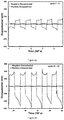
- the positive and negative overpotentials during charging and discharging are shown in FIG. 2 . It is clear that the negative overpotential is significantly larger than the positive overpotential.
- the positive overpotential varies between 5.7 mV and 9.8 mV (with an average value of 6.7 mV) while the negative varies between ⁇ 21.5 mV and ⁇ 69.3 mV (with an average value of ⁇ 47.9 mV).
- the positive overpotential varies between ⁇ 5.0 mV and ⁇ 9.4 mV (with an average value of ⁇ 6.8 mV) while the negative varies between 25.3 mV and 67.3 mV (with an average value of 52.2 mV).
- the negative overpotential is almost an order of magnitude larger than that of the positive. This difference between the negative and positive overpotentials is in agreement with the slower kinetics usually observed for V II /V III with respect to V IV /V V oxidation-reduction.
- FIG. 1 shows the data shown in FIG. 1 from the second cycle in a series of multiple-cycle experiments. So as to show the increase in overpotential (i.e. decrease in voltage efficiency) during operation, the cell was run for 47 charging-discharging cycles.
- FIG. 3 shows the positive and negative overpotentials during the (a) first 5 and (b) final 5 cycles of the 47 cycles. It will be appreciated from a review of this figure that for all cycles the negative overpotential is significantly larger than the positive. Furthermore, the negative overpotential increases with cycle number. In fact, by cycle 43, the negative overpotential has approximately tripled (see FIG. 3 ( b ) ). The positive overpotential, however, shows very little change with cycle number.
- FIG. 4 shows the positive overpotentials in FIG. 3 when replotted on a more sensitive y-axis scale, from which it can be seen that the positive overpotentials have decreased by ⁇ 1 mV over the 47 cycles.
- WO2014/142968 discloses a flow battery which includes a cell that has a first and a second electrode and an electrolyte separator layer arranged between the electrodes.
- a supply/storage system is external of the cell and includes a first vessel connected in a first loop with the first electrode and a second vessel connected in a second loop with the second electrode. The first loop and the second loop are isolated from each other.
- the supply/storage system is configured to fluidly connect the first loop and the second loop to move a second liquid electrolyte from the second vessel into a first liquid electrolyte in the first vessel responsive to a half-cell potential at the first electrode being less than a defined threshold half-cell potential.
- this method focuses on the isolated treatment of either the positive or negative electrodes through oxidation of the electrode and it does not facilitate multiple reactivations and deactivations of electrodes.
- a method for improving the energy efficiency of a vanadium flow battery, VFB comprising simultaneously reconditioning the negative electrode and the positive electrode of the VFB.
- the step of reconditioning the VFB comprises electrochemically reactivating the positive electrode and the negative electrode of the VFB.
- the step of electrochemically reactivating the positive electrode and the negative electrode comprises applying an activation potential to the negative electrode for V II /V III oxidation-reduction and applying an activation potential to the positive electrode for V IV /V V oxidation-reduction.
- the activation potential of the positive electrode corresponds to the negative half-cell working potential following operating the VFB for a number of charge and discharge cycles and the activation potential of the negative electrode corresponds to the positive half-cell working potential following operating the VFB for a number of charge and discharge cycles.
- the activation potential of the positive electrode corresponds to the negative half-cell working potential and the activation potential of the negative electrode corresponds to the positive half-cell working potential.
- the step of applying the activation potential to the positive electrode and to the negative electrode comprises the steps of switching the positive half-cell and the negative half-cell electrodes of the VFB following operating the VFB for a number of charge and discharge cycles.
- the step of overdischarging the electrolytes at the negative electrode and the positive electrode by preventing the pumping of the electrolytes of the VFB during a discharge cycle.
- the step of re-establishing the state of charge, SoC, of the electrolyte in the positive half-cell and in the negative half-cell to the operating SoCs comprises the step of pumping the electrolytes of the VFB prior to commencing a charging cycle of the VFB.
- the step of operating the VFB for a number of charge and discharge cycles comprises operating the VFB for an initial charging cycle.
- the step of operating the VFB for a number of charge and discharge cycles comprises operating the VFB for an initial controlled charging cycle.
- VFB vanadium flow battery
- VFB vanadium flow battery
- the means for reconditioning the VFB comprises means for electrochemically reactivating the positive electrode and/or the negative electrode of the VFB.
- VFB vanadium flow battery
- a computer program comprising program instructions for causing a computer program to carry out the above method which may be embodied on a record medium, carrier signal or read-only memory.
- FIG. 1 shows the cell potential, cell open-circuit potential, each half-cell working potential and the positive and negative probe potentials for the second charging and discharging cycle of a vanadium flow battery (VFB);
- VFB vanadium flow battery
- FIG. 2 shows a plot of the positive and negative overpotential for the charging and discharging data shown in FIG. 1 ;
- FIG. 3 shows a plot of the positive and negative overpotentials during (a) the first 5 cycles and (b) the final 5 cycles of 47 cycles for the VFB of FIG. 1 ;
- FIG. 4 shows a plot of the positive overpotentials during (a) the first 5 cycles and (b) the final 5 cycles for the VFB of FIG. 1 ;
- FIG. 5 shows a plot of the negative overpotentials versus probe potential during (a) discharging and (b) charging for the first 5 cycles and final 5 cycles of 47 cycles for the VFB of FIG. 1 ;
- FIG. 5 c shows a table of the approximate positive overpotentials at probe potentials of 1.01 V and approximate negative overpotentials at probe potentials of ⁇ 0.42 V during charging and discharging for the first 5 and the final 5 cycles of 47 cycles for the VFB of FIG. 1 ;
- FIG. 6 shows the normalised activities obtained from both cyclic voltammetry and electrochemical impedance spectroscopy for each of 6 carbon materials for both V II /V III and V IV /V V . Also shown are the bands of operating potentials experienced by both the positive and negative half-cells during charging and discharging for the VFB of FIG. 1 ;
- FIG. 7 shows the process flow of the first embodiment of the method of the present invention
- FIG. 8 shows the process flow of the second embodiment of the method of the present invention.
- FIG. 9 shows a plot of the positive and the negative overpotentials during (a) the first 5 cycles and (b) final 5 cycles of 40 cycles after switching the electrodes of the VFB of FIG. 1 in accordance with the first embodiment of the method of the present invention
- FIG. 9 c shows a table of the approximate positive overpotentials at probe potentials of 1.01 V and approximate negative overpotentials at probe potentials of ⁇ 0.42 V during charging and discharging for the first 5 cycles and the final 5 cycles of 47 cycles of the VFB of FIG. 1 before switching the electrodes and the first 5 cycles and final 5 cycles of 40 cycles after switching the electrodes in accordance with the first embodiment of the method of the present invention;
- FIG. 10 shows a plot of the positive and the negative overpotentials during (a) the first 5 cycles of 47 cycles of the VFB of FIG. 1 before switching the electrodes and (b) the first 5 cycles of 40 cycles after switching the electrodes in accordance with the first embodiment of the method of the present invention
- FIG. 11 shows a plot of the positive overpotentials during (a) the first 5 cycles and (b) the final 5 cycles of 47 cycles the VFB of FIG. 1 before switching the electrodes and (c) the first 5 cycles and (d) the final 5 cycles of 40 cycles after switching the electrodes in accordance with the first embodiment of the method of the present invention
- FIG. 12 shows a plot of the negative overpotentials versus probe potential during (a) discharging and (b) charging for the final 5 cycles of 47 cycles before switching the electrodes of the VFB of FIG. 1 and the first 5 cycles of 40 cycles after switching the electrodes in accordance with the first embodiment of the method of the present invention
- FIG. 13 shows a plot of both the positive and the negative overpotentials, both before (left hand side) and after (right hand side) the activation step.
- the last 5 cycles of 34 cycles before the activation step are shown on the left hand side and the first 5 cycles of 54 cycles after the activation step are shown on the right hand side.
- the activation step is in accordance with the second embodiment of the method of the present invention.
- FIG. 14 shows a plot of the negative overpotential at a probe potential of ⁇ 0.43 V (corresponding to a particular SoC) for both the 34 cycles before (left hand side) and the 54 cycles after (right hand side) the activation step in accordance with the second embodiment of the method of the present invention.
- the present invention provides a method and system for increasing the energy efficiency of a vanadium flow battery by reducing the overpotential which occurs during the charging and discharging process. This is achieved by reconditioning the VFB electrodes. This reconditioning of the VFB electrodes can be performed simultaneously. The reconditioning can be performed before normal operation of the VFB has commenced. The reconditioning can also be performed after operating the VFB for a number of charge and discharge cycles. Each reconditioning can be performed for any duration. Furthermore, the reconditioning can be repeated on many occasions, such as for example whenever the voltage efficiency of the VFB has reduced.
- FIG. 5 shows plots of negative overpotentials versus probe potential during (a) discharging and (b) charging for the first 5 cycles (dashed lines) and final 5 cycles (dotted lines) cycles (of 47 cycles) of the evaluation described in the background to the invention with respect to FIGS. 1 to 4 .
- the negative probe potential is a function of [V II ]/[V III ], and hence a function of the SoC.
- the probe potential region of operation has changed with cycle number, but there are regions of probe potential that are common to both sets of curves (i.e. regions of the same SoC) and at these common potentials, the overpotentials for the later cycles are much larger than those for the earlier cycles.
- the change in overpotential is not due to a change in the SoC.
- the change in overpotential is not due to changes in temperature, since the temperature was relatively constant for the duration of these 47 cycles (the temperature for the first 5 cycles was 23.7 ⁇ 0.7° C., and the temperature for the last 5 cycles was 23.0 ⁇ 0.6° C.).
- FIG. 5( b ) shows a plot of negative overpotentials versus probe potential during charging.
- the overpotential can be seen to have tripled at selected probe potentials (i.e. SoC).
- SoC probe potentials
- the substantial increase in negative overpotential is shown more clearly in FIG. 5 c , where the negative overpotentials at negative probe potentials of ⁇ 0.42 V during charging and discharging for the first 5 and the final 5 cycles (of 47 cycles) are summarised.
- the positive overpotentials at positive probe potentials of 1.01 V during charging and discharging for these cycles This shows that there is very little change ( ⁇ 1 mV) in the positive overpotential.
- FIG. 6 shows the bands of operating potentials for both the positive (right hand vertical line) and negative (left hand vertical line) half-cells from the results discussed with reference to FIG. 1 to FIG. 5 . Also shown in FIG. 6 are the normalised activities obtained from both cyclic voltammetry and electrochemical impedance spectroscopy for each of 6 carbon materials for both V II /V III and V IV V V . It is clear from this figure that the negative half-cell operating potential is negative enough to cause deactivation of the electrode for V II /V III . Thus, it is unsurprising that the overpotential of the negative half-cell during cycling became progressively worse over the 47 cycles.
- the positive half-cell working potential is positive enough to cause activation of the electrode for V II /V III oxidation-reduction.
- the negative half-cell working potential is negative enough to cause activation of the electrode for V IV /V V oxidation-reduction.
- the overpotential increases at the negative electrode and sometimes at the positive electrode. This results in a decrease in the energy efficiency of the battery.
- the present invention reduces this overpotential by applying activation potentials to the negative and positive electrode, in order to minimise the overpotentials of both electrodes. Accordingly, by changing the activity (i.e. the kinetics of the V IV /V V or V II /V III redox couples) at the electrodes by anodisation or cathodisation of the electrode, the energy efficiency of the system can be increased.
- the present invention describes a number of different embodiments for the in-situ activation treatment of the electrodes in a VFB.
- any other suitable method for treatment of the electrodes could equally well be used in order to reduce the overpotential during battery operation.
- the overpotential is reduced through a technique which involves switching the positive and negative half-cells.
- This switching results in an increase in electrode kinetics and, therefore, an increase in energy efficiency.
- the number of cycles is arbitrary. The ideal number can be system dependent since it can be dependent on the ratio of electrolyte in the cells and electrolyte in the reservoirs. Furthermore the number can be dependent on how the battery was cycled, for example whether the SoC is between 20 and 80% or some other range and whether the current density was 100 mA m ⁇ 2 or some other value.
- step 700 the electrolyte in the negative and positive half-cells are drained into their respective reservoirs.
- the electrolyte tubes are then clamped (step 705 ). All electrolyte inputs and outputs from each side of the cell can then be disconnected (step 710 ).
- step 715 the negative reservoir is then connected to the positive half-cell and the positive reservoir connected to the negative half-cell and the electrolyte allowed to flow again.
- the electrode that formerly contained V II /V III and was the negative electrode now contains V IV /V V and is now the positive electrode while the electrode that formerly contained V IV /V V and was the positive electrode now contains V II /V III and is now the negative electrode.
- the new positive electrode had been treated at reducing potentials while the new negative electrode had been treated at oxidising potentials. This results in minimising the overpotentials on both electrodes and re-establishing energy efficiency through the reconditioning of the electrodes.
- the electrolyte flow is turned off during discharging of the system when the current is still on by turning off the pumps (step 800 ). This results in the electrolyte in the positive and negative half-cells being overdischarged while the electrolyte outside of the cell, such as in the reservoirs, stays at the original operating state of charge (SoC).
- SoC state of charge
- the electrode and electrolyte potentials will correspond to activation potentials for the respective electrodes causing both the negative and positive electrodes to be reactivated (see FIG. 6 ).
- the method of the second embodiment thus simultaneously reconditions the positive and negative electrodes using suitable potentials while the electrolyte pumps are turned off.
- This method is fast, efficient and well understood, it allows VFB electrodes to be routinely reconditioned in-situ.
- the electrolyte flow is turned off in this second embodiment of the method of the present invention. In this manner, the treatment is performed quickly (since only a fraction of the electrolyte is used), with a region of treatment potentials that causes activation can be easily accessed.
- the electrolyte that is left in the reservoirs and tubes can be used to facilitate the re-establishment of SoC to normal operating levels without electrochemical charging of the electrolyte.
- the pumps should be turned on again before the application of any significant current, so that the electrolyte in the reservoirs will re-establish the SoC of the electrolyte in the half-cells back to operating SoCs (step 805 ). It is important to re-establish SoC of the electrolyte in this manner, or by using a very small charging current, since the large overpotentials that are required for conversion of V III to V IV and vice-versa can diminish or cancel the beneficial effects of the in-situ electrochemical treatment.
- the second embodiment of the invention can also be implemented after the initial charge from the starting 50:50 V III /V IV electrolyte (which is often used when commissioning batteries and after ‘mixing’ of electrolytes for re-establishing of battery capacity). Charging at these SoCs requires relatively high overpotentials for conversion of V III to V IV and vice-versa. These overpotentials and resulting high cathodic and anodic potentials at the negative and positive electrodes, respectively can cause the activity of the electrodes to decrease. Therefore, since the kinetics of the V III /V IV redox couple are very slow, very small currents should be used during initial charging until all V III is converted to V IV at the positive electrode and all V IV is converted to V III at the negative electrode.
- the new V III /V IV electrolyte should be added at a slow pump rate, so that most of the charging occurs under normal operating conditions, that is under conditions of fast kinetics such as those of the V II /V III and V IV /V V couples. In this manner, the V III /V IV is converted primarily by chemical reactions in solution to the redox couples of operating electrolytes.
- a third embodiment of the method of the present invention will now be described.
- the polarity of the system is changed by overdischarging a battery while pumping of the electrolyte continues.
- This is in contrast to the second embodiment of the invention, where the pumping of the electrolyte was turned off.
- the negative electrolyte changes from V II /V III to V IV /V V while the positive electrolyte changes from V IV /V V to V II /V III .
- the negative electrode becomes the positive electrode
- the positive electrode becomes the negative electrode.
- the polarity of the battery is switched without the need for the redirection of the electrolyte.
- the method of the first embodiment of the invention can be carried out directly after a cell has undergone 47 charge and discharge cycles.
- a series of charging and discharging cycles can then be performed between the ‘control’ potential previously mentioned and the overpotentials approximated as described for FIG. 2 after the positive and negative half cells have been switched.
- FIG. 9 ( a ) The results for the first 5 cycles after the switching of the positive and negative half cells in accordance with the first embodiment of the present invention are shown in FIG. 9 ( a ) . It is clear by comparing FIG. 3( a ) , which illustrates the first five cycles before the switch, with FIG. 9 a that the negative overpotentials have decreased after switching. The results for cycles 36-40 after switching are shown in FIG. 9( b ) . If this figure is compared against FIG. 3( b ) , which illustrates the final five cycles before switching (namely cycles 43 to 47), it can be seen that although there has been some increase in the negative overpotential over the 40 cycles ( ⁇ 20 mV), the overpotential is still much less than that before switching. Thus, not only does switching appear to improve the performance of the negative half-cell initially, the improvement remains even at 40 cycles after switching. The positive and negative overpotentials during these cycles are summarised in FIG. 9 c.
- the overpotentials during (a) the first 5 (of 47 cycles) before switching the electrodes and (b) the first 5 cycles after switching the electrodes are compared more closely in FIG. 10 by plotting them on a more sensitive y-axis scale. It can be seen that the negative overpotentials after switching are in some cases significantly less than those with no treatment.
- FIG. 11 illustrates a comparison between the positive overpotentials during (a) the first 5 cycles and (b) the final 5 cycles (of 47 cycles) before switching with (c) the first 5 cycles and (d) the final 5 cycles (of 40 cycles) after switching.
- the positive overpotential remains low ( ⁇ 13 mV). Thus, it can be seen that switching does not cause significant changes to the positive overpotential.
- FIG. 12 illustrates the negative overpotentials versus negative probe potential (i.e. a function of the SoC) during (a) discharging and (b) charging for the final 5 cycles before switching the electrodes (dotted lines) and for the first 5 cycles after switching the electrodes (solid lines) are shown.
- the overpotentials after switching are smaller than those before switching in these ranges: i.e. for the same SoC. This shows that the decrease in overpotential is indeed due to the treatment of the electrode.
- the treatment has resulted in the overpotential being divided by more than three; i.e. a reduction of the overpotential to less than that of fresh felt (as shown in FIG. 9 c ).
- the improvement is ascribed to the fact that the positive half-cell operating potential is positive enough to cause activation of the electrode for V II /V III .
- the method of the second embodiment of the invention can be carried out directly after a cell has undergone 34 charge and discharge cycles. After overdischarging the electrolyte in each half-cell, the overdischarged electrolyte can be allowed to sit in its respective half-cell for 1 hour or more. A series of charging and discharging cycles can then be performed between the ‘control’ potentials previously mentioned and the overpotentials approximated as described for FIG. 2 after the positive and negative half-cell electrodes have been reactivated.
- FIG. 13 compares the results for the first 5 cycles after the electrode activation with the last 5 cycles before electrode activation in accordance with the second embodiment of the present invention. It is clear by comparing the left hand side of FIG. 13 , which illustrates the first five cycles before the switch, with the right hand side of FIG. 13 that the negative overpotentials have decreased significantly after activation. As before, the change in positive overpotential is almost insignificant, due to the fact that its magnitude is so small to begin with. To more clearly illustrate the changes in negative overpotential with time, the overpotential at a given SoC was recorded for each cycle, both before and after activation.
- FIG. 14 shows a plot of negative overpotential (for a probe potential of ⁇ 0.43 V) vs. time for both the 34 cycles before and the 54 cycles after electrode activation. Both before and after activation, the negative overpotential increases slowly with time. However, even 54 cycles after activation, it is still much lower than the overpotential before activation. Thus, not only does activation appear to improve the performance of the negative half-cell initially, the improvement remains even at 54 cycles after activation.
- the present invention provides numerous advantages. By minimising overpotentials at the carbon electrodes of flow batteries through reconditioning the battery by activating the electrodes, the efficiency of the battery is improved.
- the method can also be easily applied to large-scale or small scale VFBs, leading to significant improvements in energy efficiencies, and thus reduction in the operating costs of VFBs.
- the decrease in overpotentials means that the potentials experienced by the electrodes will be less extreme. This results in a decrease in hydrogen and oxygen evolution, as well as other undesired side reactions. As a result, the colombic efficiency as well as the voltage efficiency is increased. Furthermore, less extreme potentials at the electrodes results in less degradation of the electrodes, thereby increasing battery life.
- the method of the present invention also has the advantage that it can be applied in-situ, and in most embodiments can be applied without the need for disassembly of the system.
- the embodiments in the invention described with reference to the drawings may comprise a computer apparatus and/or processes performed in a computer apparatus.
- the invention may comprise computer programs, particularly computer programs stored on or in a carrier adapted to bring the invention into practice.
- the program may be in the form of source code, object code, or a code intermediate source and object code, such as in partially compiled form or in any other form suitable for use in the implementation of the method according to the invention.
- the carrier may comprise a storage medium such as ROM, e.g. CD ROM, or magnetic recording medium, e.g. a floppy disk or hard disk.
- the carrier may be an electrical or optical signal which may be transmitted via an electrical or an optical cable or by radio or other means.
Landscapes
- Engineering & Computer Science (AREA)
- Life Sciences & Earth Sciences (AREA)
- Manufacturing & Machinery (AREA)
- Sustainable Development (AREA)
- Sustainable Energy (AREA)
- Chemical & Material Sciences (AREA)
- Chemical Kinetics & Catalysis (AREA)
- Electrochemistry (AREA)
- General Chemical & Material Sciences (AREA)
- Power Engineering (AREA)
- Secondary Cells (AREA)
Abstract
Description
Claims (9)
Applications Claiming Priority (4)
| Application Number | Priority Date | Filing Date | Title |
|---|---|---|---|
| EP15183421 | 2015-09-02 | ||
| EP15183421 | 2015-09-02 | ||
| EP15183421.5 | 2015-09-02 | ||
| PCT/EP2016/070728 WO2017037239A1 (en) | 2015-09-02 | 2016-09-02 | A method and system for improving the energy efficiency and for reconditioning of a vanadium flow battery |
Publications (2)
| Publication Number | Publication Date |
|---|---|
| US20180331382A1 US20180331382A1 (en) | 2018-11-15 |
| US11075396B2 true US11075396B2 (en) | 2021-07-27 |
Family
ID=54072677
Family Applications (1)
| Application Number | Title | Priority Date | Filing Date |
|---|---|---|---|
| US15/756,704 Expired - Fee Related US11075396B2 (en) | 2015-09-02 | 2016-09-02 | Method and system for improving the energy efficiency and for reconditioning of a vanadium flow battery |
Country Status (3)
| Country | Link |
|---|---|
| US (1) | US11075396B2 (en) |
| EP (1) | EP3345237A1 (en) |
| WO (1) | WO2017037239A1 (en) |
Families Citing this family (2)
| Publication number | Priority date | Publication date | Assignee | Title |
|---|---|---|---|---|
| WO2019131944A1 (en) * | 2017-12-28 | 2019-07-04 | 昭和電工株式会社 | Redox flow battery and operation method therefor |
| US12444758B2 (en) * | 2021-08-19 | 2025-10-14 | Cummins Inc. | Fuel cell regeneration |
Citations (6)
| Publication number | Priority date | Publication date | Assignee | Title |
|---|---|---|---|---|
| EP2339682A1 (en) | 2009-10-29 | 2011-06-29 | Beijing Prudent Century Technology Co. Ltd. | Redox flow battery and method for continually operating the redox flow battery for a long time |
| WO2014088601A1 (en) | 2012-12-09 | 2014-06-12 | United Technologies Corporation | Flow battery with voltage-limiting device |
| WO2014142968A1 (en) | 2013-03-15 | 2014-09-18 | United Technologies Corporation | Reactivation of flow battery electrode by exposure to oxidizing solution |
| CN104143646A (en) | 2013-05-09 | 2014-11-12 | 中国科学院大连化学物理研究所 | Flow energy storage cell or pile running method |
| US20160049673A1 (en) * | 2013-03-30 | 2016-02-18 | Le System Co., Ltd. | Redox flow battery and method of operating the same |
| US20160285123A1 (en) * | 2013-11-05 | 2016-09-29 | Lotte Chemical Corporation | Method for operating redox flow battery |
-
2016
- 2016-09-02 US US15/756,704 patent/US11075396B2/en not_active Expired - Fee Related
- 2016-09-02 EP EP16770895.7A patent/EP3345237A1/en not_active Withdrawn
- 2016-09-02 WO PCT/EP2016/070728 patent/WO2017037239A1/en not_active Ceased
Patent Citations (7)
| Publication number | Priority date | Publication date | Assignee | Title |
|---|---|---|---|---|
| EP2339682A1 (en) | 2009-10-29 | 2011-06-29 | Beijing Prudent Century Technology Co. Ltd. | Redox flow battery and method for continually operating the redox flow battery for a long time |
| WO2014088601A1 (en) | 2012-12-09 | 2014-06-12 | United Technologies Corporation | Flow battery with voltage-limiting device |
| WO2014142968A1 (en) | 2013-03-15 | 2014-09-18 | United Technologies Corporation | Reactivation of flow battery electrode by exposure to oxidizing solution |
| US20160013505A1 (en) * | 2013-03-15 | 2016-01-14 | United Technologies Corporation | Reactivation of flow battery electrode by exposure to oxidizing solution |
| US20160049673A1 (en) * | 2013-03-30 | 2016-02-18 | Le System Co., Ltd. | Redox flow battery and method of operating the same |
| CN104143646A (en) | 2013-05-09 | 2014-11-12 | 中国科学院大连化学物理研究所 | Flow energy storage cell or pile running method |
| US20160285123A1 (en) * | 2013-11-05 | 2016-09-29 | Lotte Chemical Corporation | Method for operating redox flow battery |
Non-Patent Citations (2)
| Title |
|---|
| PCT International Search Report for PCT International Patent Application No. PCT/EP2016/070728; dated Nov. 11, 2016; (4 pages). |
| PCT Written Opinion for PCT International Patent Application No. PCT/EP2016/070728; dated Nov. 11, 2016; (5 pages). |
Also Published As
| Publication number | Publication date |
|---|---|
| US20180331382A1 (en) | 2018-11-15 |
| WO2017037239A1 (en) | 2017-03-09 |
| EP3345237A1 (en) | 2018-07-11 |
Similar Documents
| Publication | Publication Date | Title |
|---|---|---|
| AU2021410085B2 (en) | Reverse polarity refresh method and redox flow battery system | |
| Wang et al. | Reduction of capacity decay in vanadium flow batteries by an electrolyte-reflow method | |
| Khaki et al. | Voltage loss and capacity fade reduction in vanadium redox battery by electrolyte flow control | |
| US8668997B2 (en) | System and method for sensing and mitigating hydrogen evolution within a flow battery system | |
| KR101809332B1 (en) | Regenerating module for electrolyte of flow battery and regenerating method for electrolyte of flow battery using the same | |
| JP7558182B2 (en) | Systems and methods for controlling a multi-state electrochemical cell - Patents.com | |
| US9257710B2 (en) | Flow battery start-up and recovery management | |
| JP6547002B2 (en) | Method of treating liquid electrolyte | |
| EP4152474B1 (en) | Charging method and apparatus, vehicle, and computer readable storage medium | |
| JP6408140B2 (en) | Flow battery electrode regeneration | |
| US11075396B2 (en) | Method and system for improving the energy efficiency and for reconditioning of a vanadium flow battery | |
| CN103887524A (en) | Modified treatment method of positive electrode graphite felt electrode of all-vanadium redox flow battery | |
| JP2006147374A (en) | Operation method of vanadium redox flow battery system | |
| US5436087A (en) | Process for reducing unwanted specific electro chemical conversion in rechargeable batteries | |
| CN115020756B (en) | Zinc-bromine/iodine double flow battery | |
| Xu et al. | Conversion-intercalation competing behaviour of halogen storage on graphite electrode from fluid ZnCl 2/ZnBr 2 hydrates | |
| US20230097875A1 (en) | Ferric ion reduction system to enable electrolyte rebalance within an iron flow battery | |
| WO2024025954A1 (en) | Rebalancing methods and systems for redox flow batteries | |
| CN110710042A (en) | Redox flow battery and method for operating a redox flow battery | |
| CA2970178A1 (en) | Method for regenerating the electrolyte solution of a redox flow battery | |
| KR20210053785A (en) | Battery management system and method for controlling battery charging | |
| Arai | Introduction—General features of metal-air batteries | |
| CN120878892B (en) | Flow battery system for inhibiting ion migration based on external electric field and inhibition method thereof | |
| KR102474181B1 (en) | Method of synthesizing electroyte for vanadium redox battery | |
| WO2024191401A1 (en) | A method for regenerating electrolytes of an all-iron flow battery |
Legal Events
| Date | Code | Title | Description |
|---|---|---|---|
| FEPP | Fee payment procedure |
Free format text: ENTITY STATUS SET TO UNDISCOUNTED (ORIGINAL EVENT CODE: BIG.); ENTITY STATUS OF PATENT OWNER: SMALL ENTITY |
|
| FEPP | Fee payment procedure |
Free format text: ENTITY STATUS SET TO SMALL (ORIGINAL EVENT CODE: SMAL); ENTITY STATUS OF PATENT OWNER: SMALL ENTITY |
|
| STPP | Information on status: patent application and granting procedure in general |
Free format text: DOCKETED NEW CASE - READY FOR EXAMINATION |
|
| STPP | Information on status: patent application and granting procedure in general |
Free format text: NON FINAL ACTION MAILED |
|
| STPP | Information on status: patent application and granting procedure in general |
Free format text: RESPONSE TO NON-FINAL OFFICE ACTION ENTERED AND FORWARDED TO EXAMINER |
|
| STPP | Information on status: patent application and granting procedure in general |
Free format text: NOTICE OF ALLOWANCE MAILED -- APPLICATION RECEIVED IN OFFICE OF PUBLICATIONS |
|
| AS | Assignment |
Owner name: UNIVERSITY OF LIMERICK, IRELAND Free format text: ASSIGNMENT OF ASSIGNORS INTEREST;ASSIGNORS:LYNCH, ROBERT PATRICK;QUILL, NATHAN;BOURKE, ANDREA;AND OTHERS;SIGNING DATES FROM 20210510 TO 20210511;REEL/FRAME:056219/0127 |
|
| STPP | Information on status: patent application and granting procedure in general |
Free format text: PUBLICATIONS -- ISSUE FEE PAYMENT VERIFIED |
|
| STCF | Information on status: patent grant |
Free format text: PATENTED CASE |
|
| FEPP | Fee payment procedure |
Free format text: MAINTENANCE FEE REMINDER MAILED (ORIGINAL EVENT CODE: REM.); ENTITY STATUS OF PATENT OWNER: SMALL ENTITY |
|
| LAPS | Lapse for failure to pay maintenance fees |
Free format text: PATENT EXPIRED FOR FAILURE TO PAY MAINTENANCE FEES (ORIGINAL EVENT CODE: EXP.); ENTITY STATUS OF PATENT OWNER: SMALL ENTITY |
|
| STCH | Information on status: patent discontinuation |
Free format text: PATENT EXPIRED DUE TO NONPAYMENT OF MAINTENANCE FEES UNDER 37 CFR 1.362 |
|
| FP | Lapsed due to failure to pay maintenance fee |
Effective date: 20250727 |