US11075343B2 - Organic light emitting compounds and organic light emitting devices including the same - Google Patents
Organic light emitting compounds and organic light emitting devices including the same Download PDFInfo
- Publication number
- US11075343B2 US11075343B2 US15/405,766 US201715405766A US11075343B2 US 11075343 B2 US11075343 B2 US 11075343B2 US 201715405766 A US201715405766 A US 201715405766A US 11075343 B2 US11075343 B2 US 11075343B2
- Authority
- US
- United States
- Prior art keywords
- groups
- substituted
- unsubstituted
- group
- light emitting
- Prior art date
- Legal status (The legal status is an assumption and is not a legal conclusion. Google has not performed a legal analysis and makes no representation as to the accuracy of the status listed.)
- Active
Links
- 0 [1*]C1([2*])c2ccccc2-c2c1ccc1c2-c2ccccc2O1.[1*]C1([2*])c2ccccc2-c2cc3c(cc21)-c1ccccc1O3.[1*]C1([2*])c2ccccc2-c2cc3c(cc21)Oc1ccccc1-3.[1*]C1([2*])c2ccccc2-c2ccc3c(c21)-c1ccccc1O3.[1*]C1([2*])c2ccccc2-c2ccc3c(c21)Oc1ccccc1-3 Chemical compound [1*]C1([2*])c2ccccc2-c2c1ccc1c2-c2ccccc2O1.[1*]C1([2*])c2ccccc2-c2cc3c(cc21)-c1ccccc1O3.[1*]C1([2*])c2ccccc2-c2cc3c(cc21)Oc1ccccc1-3.[1*]C1([2*])c2ccccc2-c2ccc3c(c21)-c1ccccc1O3.[1*]C1([2*])c2ccccc2-c2ccc3c(c21)Oc1ccccc1-3 0.000 description 28
- FJSHLRUVNRKPDR-UHFFFAOYSA-N C1=CC(C2=CC3=C(C=C2)C2=C/C=C/C=C\2N3C2=CC3=C(C=CC=C3)C3=C2C=CC=C3)=CC(N2C3=C(C=CC=C3)C3=C2C=CC=C3)=C1.C1=CC(C2=CC3=C(C=C2)C2=C\C=C/C=C\2N3C2=CC=C3SC4=C(C=CC=C4)C3=C2)=CC(N2C3=C(C=CC=C3)C3=C2C=CC=C3)=C1.C1=CC2=C(C=C1)C1=C(C=CC=C1)C(N1C3=C(C=CC(C4=C/C(N5C6=C(C=CC=C6)C6=C5C=CC=C6)=C5/C6=C(C=CC=C6)O/C5=C\4)=C3)C3=C/C=C/C=C\31)=C2.C1=CC=C2C(=C1)C1=C(C=C(C3=C\C4=C(\C=C/3)OC3=C4C=C(N4C5=C(C=CC=C5)C5=C4C=CC=C5)C=C3)C=C1)N2C1=CC2=C3C=CC=CC3=C3C=CC=CC3=C2C=C1 Chemical compound C1=CC(C2=CC3=C(C=C2)C2=C/C=C/C=C\2N3C2=CC3=C(C=CC=C3)C3=C2C=CC=C3)=CC(N2C3=C(C=CC=C3)C3=C2C=CC=C3)=C1.C1=CC(C2=CC3=C(C=C2)C2=C\C=C/C=C\2N3C2=CC=C3SC4=C(C=CC=C4)C3=C2)=CC(N2C3=C(C=CC=C3)C3=C2C=CC=C3)=C1.C1=CC2=C(C=C1)C1=C(C=CC=C1)C(N1C3=C(C=CC(C4=C/C(N5C6=C(C=CC=C6)C6=C5C=CC=C6)=C5/C6=C(C=CC=C6)O/C5=C\4)=C3)C3=C/C=C/C=C\31)=C2.C1=CC=C2C(=C1)C1=C(C=C(C3=C\C4=C(\C=C/3)OC3=C4C=C(N4C5=C(C=CC=C5)C5=C4C=CC=C5)C=C3)C=C1)N2C1=CC2=C3C=CC=CC3=C3C=CC=CC3=C2C=C1 FJSHLRUVNRKPDR-UHFFFAOYSA-N 0.000 description 2
- JJTBXNKLJHULPQ-UHFFFAOYSA-N C1=CC2=C(C=C1)C1=C(/C=C\C(C3=CC4=C(C=C3)N(C3=C/C=C5\OC6=C(C=CC=C6)\C5=C\3)C3=C4C4=CC=C5/C=C\C=C/C5=C4C=C3)=C/1)O2.C1=CC=C(N2C3=C(/C=C(C4=CC=CC5=C4SC4=C5C=CC=C4)\C=C/3)C3=C/2C2=CC=C4C=CC=CC4=C2\C=C/3)C=C1.C1=CC=C(N2C3=C(C=C(C4=C5\OC6=C(C=CC=C6)\C5=C/C=C\4)C=C3)C3=C2C=CC2=C4/C=C\C=C/C4=CC=C23)C=C1.C1=CC=C(N2C3=C(C=CC=C3)C3=C2C=CC2=CC=C(C4=CC(C5=CC6=C(C=C5)N(C5=CC=CC=C5)C5=C6C=CC6=C7/C=C\C=C/C7=CC=C65)=CC=C4)C=C23)C=C1 Chemical compound C1=CC2=C(C=C1)C1=C(/C=C\C(C3=CC4=C(C=C3)N(C3=C/C=C5\OC6=C(C=CC=C6)\C5=C\3)C3=C4C4=CC=C5/C=C\C=C/C5=C4C=C3)=C/1)O2.C1=CC=C(N2C3=C(/C=C(C4=CC=CC5=C4SC4=C5C=CC=C4)\C=C/3)C3=C/2C2=CC=C4C=CC=CC4=C2\C=C/3)C=C1.C1=CC=C(N2C3=C(C=C(C4=C5\OC6=C(C=CC=C6)\C5=C/C=C\4)C=C3)C3=C2C=CC2=C4/C=C\C=C/C4=CC=C23)C=C1.C1=CC=C(N2C3=C(C=CC=C3)C3=C2C=CC2=CC=C(C4=CC(C5=CC6=C(C=C5)N(C5=CC=CC=C5)C5=C6C=CC6=C7/C=C\C=C/C7=CC=C65)=CC=C4)C=C23)C=C1 JJTBXNKLJHULPQ-UHFFFAOYSA-N 0.000 description 2
- IQHACFQXFWLAOX-UHFFFAOYSA-N C1=CC2=C(C=C1)C1=C(C=CC(C3=CC4=C(C=C3)C3=C5C=CC=CC5=C5C=CC=CC5=C3N4C3=C/C=C4\OC5=C(C=CC=C5)\C4=C\3)=C1)O2.C1=CC=C(N2C3=C(C=CC=C3)C3=C/C4=C(/C=C/32)C2=C(C=CC=C2)C2=C\C=C(C3=CC5=C(C=C3)N(C3=C/C=C6\OC7=C(C=CC=C7)\C6=C\3)C3=C6C=CC=CC6=C6C=CC=CC6=C53)/C=C\24)C=C1 Chemical compound C1=CC2=C(C=C1)C1=C(C=CC(C3=CC4=C(C=C3)C3=C5C=CC=CC5=C5C=CC=CC5=C3N4C3=C/C=C4\OC5=C(C=CC=C5)\C4=C\3)=C1)O2.C1=CC=C(N2C3=C(C=CC=C3)C3=C/C4=C(/C=C/32)C2=C(C=CC=C2)C2=C\C=C(C3=CC5=C(C=C3)N(C3=C/C=C6\OC7=C(C=CC=C7)\C6=C\3)C3=C6C=CC=CC6=C6C=CC=CC6=C53)/C=C\24)C=C1 IQHACFQXFWLAOX-UHFFFAOYSA-N 0.000 description 2
- RPUQGTNNQUCLFX-UHFFFAOYSA-N C1=CC2=C(C=C1)C1=C(O2)C(C2=CC3=C(C=C2)N(C2=C4\OC5=C(C=CC=C5)\C4=C/C=C\2)/C=C\3)=CC=C1.C1=CC=C(C2=CC3=C(C=C2)C(C2=C/C=C4\C5=C(C=CC=C5)N(C5=CC=CC=C5)\C4=C\2)=CN3C2=CC3=C(C=C2)C2=C(C=CC=C2)C2=C3C=CC=C2)C=C1.C1=CC=C(N2C(C3=CC4=C(C=C3)C3=C(C=CC=C3)C3=C4C=CC=C3)=CC3=C2C=CC(C2=CC=CC4=C2OC2=C4C=CC=C2)=C3)C=C1.C1=CC=C(N2C=CC3=C2C=CC(C2=CC4=C(C=C2)C2=C(C=CC=C2)C2=C4C=CC=C2)=C3C2=CC=CC3=C2C=CC2=C3C3=C(C=CC=C3)N2C2=CC=CC=N2)C=C1 Chemical compound C1=CC2=C(C=C1)C1=C(O2)C(C2=CC3=C(C=C2)N(C2=C4\OC5=C(C=CC=C5)\C4=C/C=C\2)/C=C\3)=CC=C1.C1=CC=C(C2=CC3=C(C=C2)C(C2=C/C=C4\C5=C(C=CC=C5)N(C5=CC=CC=C5)\C4=C\2)=CN3C2=CC3=C(C=C2)C2=C(C=CC=C2)C2=C3C=CC=C2)C=C1.C1=CC=C(N2C(C3=CC4=C(C=C3)C3=C(C=CC=C3)C3=C4C=CC=C3)=CC3=C2C=CC(C2=CC=CC4=C2OC2=C4C=CC=C2)=C3)C=C1.C1=CC=C(N2C=CC3=C2C=CC(C2=CC4=C(C=C2)C2=C(C=CC=C2)C2=C4C=CC=C2)=C3C2=CC=CC3=C2C=CC2=C3C3=C(C=CC=C3)N2C2=CC=CC=N2)C=C1 RPUQGTNNQUCLFX-UHFFFAOYSA-N 0.000 description 2
- JGFLHXPOVZTHQG-UHFFFAOYSA-N C1=CC2=C(C=C1)C1=C(O2)C(C2=CC3=C(C=C2)N(C2=C4\OC5=C(C=CC=C5)\C4=C/C=C\2)C2=C3C=CC=C2)=CC=C1.C1=CC2=C(C=C1)C1=C(O2)C(C2=CC3=C(C=C2)N(C2=CC4=C(C=C2)C2=C(C=CC=C2)C2=C4C=CC=C2)C2=C3C=CC=C2)=CC=C1.C1=CC=C(N2C3=C(C=CC=C3)C3=C/C4=C(/C=C/32)C2=C/C=C(C3=CC5=C(C=C3)N(C3=CC6=C(C=C3)C3=C(C=CC=C3)C3=C6C=CC=C3)C3=C5C=CC=C3)\C=C\2\C=C/4)C=C1.C1=CC=C(N2C3=C(C=CC=C3)C3=C2C=CC(C2=CC4=C(C=C2)OC2=C4C=CC=C2)=C3)C=C1 Chemical compound C1=CC2=C(C=C1)C1=C(O2)C(C2=CC3=C(C=C2)N(C2=C4\OC5=C(C=CC=C5)\C4=C/C=C\2)C2=C3C=CC=C2)=CC=C1.C1=CC2=C(C=C1)C1=C(O2)C(C2=CC3=C(C=C2)N(C2=CC4=C(C=C2)C2=C(C=CC=C2)C2=C4C=CC=C2)C2=C3C=CC=C2)=CC=C1.C1=CC=C(N2C3=C(C=CC=C3)C3=C/C4=C(/C=C/32)C2=C/C=C(C3=CC5=C(C=C3)N(C3=CC6=C(C=C3)C3=C(C=CC=C3)C3=C6C=CC=C3)C3=C5C=CC=C3)\C=C\2\C=C/4)C=C1.C1=CC=C(N2C3=C(C=CC=C3)C3=C2C=CC(C2=CC4=C(C=C2)OC2=C4C=CC=C2)=C3)C=C1 JGFLHXPOVZTHQG-UHFFFAOYSA-N 0.000 description 2
- NVWXCWFGBPKPLM-UHFFFAOYSA-N C1=CC2=C(C=C1)C1=CC(N3C4=C(C=CC=C4)C4=C3/C=C(C3=C/C5=C(\C=C/3)C3=C(C=CC=C3)N5C3=CC5=C(C=C3)OC3=C5C=CC=C3)\C=C/4)=CC=C1O2.C1=CC=C(C2=CC(N3C4=C(C=CC=C4)C4=C3/C=C(C3=C/C5=C(\C=C/3)C3=C(C=CC=C3)N5C3=CC=C5C(=C3)OC3=C5C=CC=C3)\C=C/4)=CC=C2)C=C1.C1=CC=C(N2C3=C(C=CC=C3)C3=C2C=C(C2=CC4=C(C=C2)C2=C(C=CC=C2)N4C2=CC4=C(C=C2)C2=C(C=CC=C2)C2=C4C=CC=C2)C=C3)C=C1.CC1(C)C2=C(C=CC=C2)C2=C1C=C(N1C3=C(C=CC=C3)C3=C1/C=C(C1=C/C4=C(\C=C/1)C1=C(C=CC=C1)N4C1=CC=C4C(=C1)OC1=C4C=CC=C1)\C=C/3)C=C2 Chemical compound C1=CC2=C(C=C1)C1=CC(N3C4=C(C=CC=C4)C4=C3/C=C(C3=C/C5=C(\C=C/3)C3=C(C=CC=C3)N5C3=CC5=C(C=C3)OC3=C5C=CC=C3)\C=C/4)=CC=C1O2.C1=CC=C(C2=CC(N3C4=C(C=CC=C4)C4=C3/C=C(C3=C/C5=C(\C=C/3)C3=C(C=CC=C3)N5C3=CC=C5C(=C3)OC3=C5C=CC=C3)\C=C/4)=CC=C2)C=C1.C1=CC=C(N2C3=C(C=CC=C3)C3=C2C=C(C2=CC4=C(C=C2)C2=C(C=CC=C2)N4C2=CC4=C(C=C2)C2=C(C=CC=C2)C2=C4C=CC=C2)C=C3)C=C1.CC1(C)C2=C(C=CC=C2)C2=C1C=C(N1C3=C(C=CC=C3)C3=C1/C=C(C1=C/C4=C(\C=C/1)C1=C(C=CC=C1)N4C1=CC=C4C(=C1)OC1=C4C=CC=C1)\C=C/3)C=C2 NVWXCWFGBPKPLM-UHFFFAOYSA-N 0.000 description 2
- CIVQQDPZWIGWAD-UHFFFAOYSA-N C1=CC2=CC(N3C4=C(C=CC=C4)C4=C3/C=C(C3=C/C5=C(\C=C/3)C3=C(C=CC=C3)N5C3=CC=C5NC6=C(C=CC=C6)C5=C3)\C=C/4)=C3C=CC=CC3=C2C=C1.C1=CC=C(C2=CC(N3C4=C(C=CC=C4)C4=C3/C=C(C3=C/C5=C(\C=C/3)C3=C(C=CC=C3)N5C3=CC=C5C=CN(C6=CC=CC=C6)C5=C3)\C=C/4)=CC=C2)C=C1.CC1(C)C2=CC3=C(C=C2C2=C1C=CC=C2)C1=C(C=CC(C2=CC4=C(C=C2)N(C2=CC=CC(C5=CC=CC=C5)=C2)C2=C4C=CC=C2)=C1)N3C1=CC=CC=C1.CC1(C)C2=CC3=C(C=C2C2=C1C=CC=C2)C1=C(C=CC(C2=CC4=C(C=C2)N(C2=CC=CC=C2)C2=C4C=CC=C2)=C1)N3C1=CC=CC=C1 Chemical compound C1=CC2=CC(N3C4=C(C=CC=C4)C4=C3/C=C(C3=C/C5=C(\C=C/3)C3=C(C=CC=C3)N5C3=CC=C5NC6=C(C=CC=C6)C5=C3)\C=C/4)=C3C=CC=CC3=C2C=C1.C1=CC=C(C2=CC(N3C4=C(C=CC=C4)C4=C3/C=C(C3=C/C5=C(\C=C/3)C3=C(C=CC=C3)N5C3=CC=C5C=CN(C6=CC=CC=C6)C5=C3)\C=C/4)=CC=C2)C=C1.CC1(C)C2=CC3=C(C=C2C2=C1C=CC=C2)C1=C(C=CC(C2=CC4=C(C=C2)N(C2=CC=CC(C5=CC=CC=C5)=C2)C2=C4C=CC=C2)=C1)N3C1=CC=CC=C1.CC1(C)C2=CC3=C(C=C2C2=C1C=CC=C2)C1=C(C=CC(C2=CC4=C(C=C2)N(C2=CC=CC=C2)C2=C4C=CC=C2)=C1)N3C1=CC=CC=C1 CIVQQDPZWIGWAD-UHFFFAOYSA-N 0.000 description 2
- JPSAOBSJGIGWQH-UHFFFAOYSA-N C1=CC2=CC=C(N3C4=C(C=CC=C4)C4=C3C=CC(C3=CC5=C(C=C3)N(C3=CC=C6C=CC=CC6=C3)C3=C5C=CC=C3)=C4)C=C2C=C1.CC1(C)C2=C(C=CC=C2)C2=C1C=C(N1C3=C(C=CC=C3)C3=C1C=CC(C1=CC4=C(C=C1)N(C1=C/C=C5/OC6=C(C=CC=C6)/C5=C\1)C1=C4C=CC=C1)=C3)C=C2.CC1(C)C2=C(C=CC=C2)C2=C1C=C(N1C3=C(C=CC=C3)C3=C1C=CC(C1=CC4=C(C=C1)N(C1=C5C=CC=CC5=C5C=CC=CC5=C1)C1=C4C=CC=C1)=C3)C=C2.CC1(C)C2=C(C=CC=C2)C2=C1C=C(N1C3=C(C=CC=C3)C3=C1C=CC(C1=CC4=C(C=C1)N(C1=CC=C5C=CC=CC5=C1)C1=C4C=CC=C1)=C3)C=C2 Chemical compound C1=CC2=CC=C(N3C4=C(C=CC=C4)C4=C3C=CC(C3=CC5=C(C=C3)N(C3=CC=C6C=CC=CC6=C3)C3=C5C=CC=C3)=C4)C=C2C=C1.CC1(C)C2=C(C=CC=C2)C2=C1C=C(N1C3=C(C=CC=C3)C3=C1C=CC(C1=CC4=C(C=C1)N(C1=C/C=C5/OC6=C(C=CC=C6)/C5=C\1)C1=C4C=CC=C1)=C3)C=C2.CC1(C)C2=C(C=CC=C2)C2=C1C=C(N1C3=C(C=CC=C3)C3=C1C=CC(C1=CC4=C(C=C1)N(C1=C5C=CC=CC5=C5C=CC=CC5=C1)C1=C4C=CC=C1)=C3)C=C2.CC1(C)C2=C(C=CC=C2)C2=C1C=C(N1C3=C(C=CC=C3)C3=C1C=CC(C1=CC4=C(C=C1)N(C1=CC=C5C=CC=CC5=C1)C1=C4C=CC=C1)=C3)C=C2 JPSAOBSJGIGWQH-UHFFFAOYSA-N 0.000 description 2
- PDJDLDUYDMHJOL-UHFFFAOYSA-N C1=CC=C(C2=C/C3=C(\C(C4=CC5=C(C=C4)OC4=C5C=CC5=C4C4=C(C=CC=C4)N5C4=CC=C5C(=C4)C4=C(C=CC=C4)C4=C5C=CC=C4)=C/2)N(C2=CC=CC=C2)C2=C3C=CC=C2)C=C1.C1=CC=C(N2C3=C(C=CC=C3)C3=C2/C=C\C2=C3\C3=C\C=C(C4=CC5=C(C=C4)OC4=C5C=CC5=C4C4=C(C=CC=C4)N5C4=C/C=C5/OC6=C(C=CC=C6)/C5=C\4)/C=C/3C3=C2C=CC=C3)C=C1.CC1(C)C2=C(C=CC(/C3=C/C=C\C4=C3OC3=C4C=CC=C3)=C2)C2=C1C1=C(C=C2)C2=C(C=CC=C2)N1C1=CC=CC=C1.CC1(C)C2=C(C=CC=C2)C2=C\C=C(C3=CC=CC(C4=CC(C5=CC6=C(C=C5)C5=C(O6)C6=C(C=C5)C5=C(C=CC(C7=CC=CC=C7)=C5)N6C5=CC=C6C(=C5)C5=C(C=CC=C5)C5=C6C=CC=C5)=CC=C4)=C3)/C=C\21 Chemical compound C1=CC=C(C2=C/C3=C(\C(C4=CC5=C(C=C4)OC4=C5C=CC5=C4C4=C(C=CC=C4)N5C4=CC=C5C(=C4)C4=C(C=CC=C4)C4=C5C=CC=C4)=C/2)N(C2=CC=CC=C2)C2=C3C=CC=C2)C=C1.C1=CC=C(N2C3=C(C=CC=C3)C3=C2/C=C\C2=C3\C3=C\C=C(C4=CC5=C(C=C4)OC4=C5C=CC5=C4C4=C(C=CC=C4)N5C4=C/C=C5/OC6=C(C=CC=C6)/C5=C\4)/C=C/3C3=C2C=CC=C3)C=C1.CC1(C)C2=C(C=CC(/C3=C/C=C\C4=C3OC3=C4C=CC=C3)=C2)C2=C1C1=C(C=C2)C2=C(C=CC=C2)N1C1=CC=CC=C1.CC1(C)C2=C(C=CC=C2)C2=C\C=C(C3=CC=CC(C4=CC(C5=CC6=C(C=C5)C5=C(O6)C6=C(C=C5)C5=C(C=CC(C7=CC=CC=C7)=C5)N6C5=CC=C6C(=C5)C5=C(C=CC=C5)C5=C6C=CC=C5)=CC=C4)=C3)/C=C\21 PDJDLDUYDMHJOL-UHFFFAOYSA-N 0.000 description 2
- JYMWUNCABKNHSP-UHFFFAOYSA-N C1=CC=C(C2=CC(N3C4=C(C=CC=C4)C4=C3/C=C(C3=C/C5=C(\C=C/3)C3=C(C=CC=C3)N5C3=CC=C5C=CC=CC5=C3)\C=C/4)=CC=C2)C=C1.CC1(C)C2=CC=C(N3C4=C(C=CC=C4)C4=C3/C=C(C3=C/C5=C(\C=C/3)C3=C(C=CC=C3)N5C3=CC5=C(C=C3)C(C)(C)C3=C5C=CC=C3)\C=C/4)C=C2C2=C1C=CC=C2 Chemical compound C1=CC=C(C2=CC(N3C4=C(C=CC=C4)C4=C3/C=C(C3=C/C5=C(\C=C/3)C3=C(C=CC=C3)N5C3=CC=C5C=CC=CC5=C3)\C=C/4)=CC=C2)C=C1.CC1(C)C2=CC=C(N3C4=C(C=CC=C4)C4=C3/C=C(C3=C/C5=C(\C=C/3)C3=C(C=CC=C3)N5C3=CC5=C(C=C3)C(C)(C)C3=C5C=CC=C3)\C=C/4)C=C2C2=C1C=CC=C2 JYMWUNCABKNHSP-UHFFFAOYSA-N 0.000 description 2
- DFVRIJJUVUJKPM-UHFFFAOYSA-N C1=CC=C(C2=CC(N3C4=C(C=CC=C4)C4=C3C=CC(C3=CC5=C(C=C3)C=CN5C3=CC=CC=C3)=C4)=CC=C2)C=C1.CC1=CC=CC(N2C=CC3=C2C=C(C2=CC4=C(C=C2)N(C2=CC=CC=C2)C2=C4C4=C(C=CC=C4)C=C2)C=C3)=C1 Chemical compound C1=CC=C(C2=CC(N3C4=C(C=CC=C4)C4=C3C=CC(C3=CC5=C(C=C3)C=CN5C3=CC=CC=C3)=C4)=CC=C2)C=C1.CC1=CC=CC(N2C=CC3=C2C=C(C2=CC4=C(C=C2)N(C2=CC=CC=C2)C2=C4C4=C(C=CC=C4)C=C2)C=C3)=C1 DFVRIJJUVUJKPM-UHFFFAOYSA-N 0.000 description 2
- BYSHATKBJHFDII-UHFFFAOYSA-N C1=CC=C(C2=CC(N3C4=C(C=CC=C4)C4=C3C=CC(C3=CC5=C(C=C3)N(C3=CC=CC=C3)C3=C5C5=C(C=C3)C3=C(C=CC=C3)O5)=C4)=CC=C2)C=C1.C1=CC=C(N2C3=C(C=C(C4=CC5=C(C=C4)N(C4=C/C=C6/OC7=C(C=CC=C7)/C6=C\4)C4=C5C=CC=C4)C=C3)C3=C2C=CC2=C3SC3=C2C=CC=C3)C=C1.C1=CC=C(N2C3=C(C=C(C4=CC5=C(C=C4)N(C4=CC=C6C=CC=CC6=C4)C4=C5C=CC=C4)C=C3)C3=C2C=CC2=C3SC3=C2C=CC=C3)C=C1.C1=CC=C(N2C3=C(C=CC=C3)C3=C2C=CC(C2=CC4=C(C=C2)N(C2=CC=CC=C2)C2=C4C4=C(C=C2)C2=C(C=CC=C2)O4)=C3)C=C1 Chemical compound C1=CC=C(C2=CC(N3C4=C(C=CC=C4)C4=C3C=CC(C3=CC5=C(C=C3)N(C3=CC=CC=C3)C3=C5C5=C(C=C3)C3=C(C=CC=C3)O5)=C4)=CC=C2)C=C1.C1=CC=C(N2C3=C(C=C(C4=CC5=C(C=C4)N(C4=C/C=C6/OC7=C(C=CC=C7)/C6=C\4)C4=C5C=CC=C4)C=C3)C3=C2C=CC2=C3SC3=C2C=CC=C3)C=C1.C1=CC=C(N2C3=C(C=C(C4=CC5=C(C=C4)N(C4=CC=C6C=CC=CC6=C4)C4=C5C=CC=C4)C=C3)C3=C2C=CC2=C3SC3=C2C=CC=C3)C=C1.C1=CC=C(N2C3=C(C=CC=C3)C3=C2C=CC(C2=CC4=C(C=C2)N(C2=CC=CC=C2)C2=C4C4=C(C=C2)C2=C(C=CC=C2)O4)=C3)C=C1 BYSHATKBJHFDII-UHFFFAOYSA-N 0.000 description 2
- FSQMGSHNFJEFIZ-UHFFFAOYSA-N C1=CC=C(C2=CC(N3C4=CC=CC=C4C4=C3C=C(C3=C/C=C5\C=CN(C6=CC=C7C(=C6)C6=C(C=CC=C6)C6=C7C=CC=C6)\C5=C\3)C=C4)=CC=C2)C=C1.C1=CC=C(N2C3=CC=CC=C3C3=C2C=C(C2=C/C=C4\C=CN(C5=CC=C6C(=C5)C5=C(C=CC=C5)C5=C6C=CC=C5)\C4=C\2)C=C3)C=C1.C1=CC=C(N2C3=CC=CC=C3C3=C2C=CC(C2=C/C=C4\C=CN(C5=CC=C6SC7=C(C=CC=C7)C6=C5)\C4=C\2)=C3)C=C1.C1=CC=C2C(=C1)C1=C(C=C(C3=CC=C4C=CN(C5=C/C=C6\SC7=C(C=CC=C7)\C6=C\5)C4=C3)C=C1)N2C1=CC=C2C=CC=CC2=C1 Chemical compound C1=CC=C(C2=CC(N3C4=CC=CC=C4C4=C3C=C(C3=C/C=C5\C=CN(C6=CC=C7C(=C6)C6=C(C=CC=C6)C6=C7C=CC=C6)\C5=C\3)C=C4)=CC=C2)C=C1.C1=CC=C(N2C3=CC=CC=C3C3=C2C=C(C2=C/C=C4\C=CN(C5=CC=C6C(=C5)C5=C(C=CC=C5)C5=C6C=CC=C5)\C4=C\2)C=C3)C=C1.C1=CC=C(N2C3=CC=CC=C3C3=C2C=CC(C2=C/C=C4\C=CN(C5=CC=C6SC7=C(C=CC=C7)C6=C5)\C4=C\2)=C3)C=C1.C1=CC=C2C(=C1)C1=C(C=C(C3=CC=C4C=CN(C5=C/C=C6\SC7=C(C=CC=C7)\C6=C\5)C4=C3)C=C1)N2C1=CC=C2C=CC=CC2=C1 FSQMGSHNFJEFIZ-UHFFFAOYSA-N 0.000 description 2
- LLSYTQMJDGDBBF-UHFFFAOYSA-N C1=CC=C(C2=CC(N3C=CC4=C\C=C(C5=CC6=C(C=C5)N(C5=C7C=CC=CC7=C7C=CC=CC7=C5)C5=CC=CC=C56)/C=C\43)=CC=C2)C=C1.C1=CC=C(N2C=CC3=C\C=C(C4=CC5=C(C=C4)N(C4=C/C=C6\OC7=C(C=CC=C7)\C6=C\4)C4=CC=CC=C45)/C=C\32)C=C1.C1=CC=C(N2C=CC3=C\C=C(C4=CC5=C(C=C4)N(C4=CC6=C(C=C4)C4=C(C=CC=C4)C4=C6C=CC=C4)C4=CC=CC=C45)/C=C\32)C=C1.C1=CC=C2C(=C1)C1=C(C=CC(C3=C/C=C4\C=CN(C5=CC=C6OC7=C(C=CC=C7)C6=C5)\C4=C\3)=C1)N2C1=C/C=C2\OC3=C(C=CC=C3)\C2=C\1 Chemical compound C1=CC=C(C2=CC(N3C=CC4=C\C=C(C5=CC6=C(C=C5)N(C5=C7C=CC=CC7=C7C=CC=CC7=C5)C5=CC=CC=C56)/C=C\43)=CC=C2)C=C1.C1=CC=C(N2C=CC3=C\C=C(C4=CC5=C(C=C4)N(C4=C/C=C6\OC7=C(C=CC=C7)\C6=C\4)C4=CC=CC=C45)/C=C\32)C=C1.C1=CC=C(N2C=CC3=C\C=C(C4=CC5=C(C=C4)N(C4=CC6=C(C=C4)C4=C(C=CC=C4)C4=C6C=CC=C4)C4=CC=CC=C45)/C=C\32)C=C1.C1=CC=C2C(=C1)C1=C(C=CC(C3=C/C=C4\C=CN(C5=CC=C6OC7=C(C=CC=C7)C6=C5)\C4=C\3)=C1)N2C1=C/C=C2\OC3=C(C=CC=C3)\C2=C\1 LLSYTQMJDGDBBF-UHFFFAOYSA-N 0.000 description 2
- WGNWTTMZHWCLGU-UHFFFAOYSA-N C1=CC=C(C2=CC3=C(C=C2)C2=C(C=C(C4=CC=CC5=C4C4=C(C=CC=C4)O5)C=C2)N3C2=C/C=C3/OC4=C(C=CC=C4)/C3=C\2)C=C1.CC1(C)C2=C(C=CC=C2)C2=C1/C=C(N1C3=C(C=CC=C3)C3=C1C=C(C1=C\C4=C(\C=C/1)C1=C(C=CC=C1)C1=C4\C4=C(/C=C\1)N(C1=CC=CC=C1)C1=C4C=CC=C1)C=C3)\C=C/2 Chemical compound C1=CC=C(C2=CC3=C(C=C2)C2=C(C=C(C4=CC=CC5=C4C4=C(C=CC=C4)O5)C=C2)N3C2=C/C=C3/OC4=C(C=CC=C4)/C3=C\2)C=C1.CC1(C)C2=C(C=CC=C2)C2=C1/C=C(N1C3=C(C=CC=C3)C3=C1C=C(C1=C\C4=C(\C=C/1)C1=C(C=CC=C1)C1=C4\C4=C(/C=C\1)N(C1=CC=CC=C1)C1=C4C=CC=C1)C=C3)\C=C/2 WGNWTTMZHWCLGU-UHFFFAOYSA-N 0.000 description 2
- UUZUYJAHEARYOZ-UHFFFAOYSA-N C1=CC=C(C2=CC3=C(C=C2)C2=C(C=CC4=C2C2=C(C=CC(/C5=C/C=C\C6=C5SC5=C6C=CC=C5)=C2)O4)N3C2=CC3=C(C=C2)C2=C(C=CC=C2)C2=C3C=CC=C2)C=C1.CC1(C)C2=C(C=CC(/C3=C/C=C\C4=C3OC3=C4C=CC=C3)=C2)C2=C1C=CC1=C2C2=C(C=CC=C2)N1C1=CC=CC=C1 Chemical compound C1=CC=C(C2=CC3=C(C=C2)C2=C(C=CC4=C2C2=C(C=CC(/C5=C/C=C\C6=C5SC5=C6C=CC=C5)=C2)O4)N3C2=CC3=C(C=C2)C2=C(C=CC=C2)C2=C3C=CC=C2)C=C1.CC1(C)C2=C(C=CC(/C3=C/C=C\C4=C3OC3=C4C=CC=C3)=C2)C2=C1C=CC1=C2C2=C(C=CC=C2)N1C1=CC=CC=C1 UUZUYJAHEARYOZ-UHFFFAOYSA-N 0.000 description 2
- XFMPPFQSDWVSOB-UHFFFAOYSA-N C1=CC=C(C2=CC3=C(C=C2)C2=CC4=C(C=C2N3C2=CC3=C(C=C2)C2=C(C=CC=C2)C2=C3C=CC=C2)OC2=C4C=CC=C2C2=C/C3=C(\C=C/2)C2=C(C=CC=C2)S3)C=C1.C1=CC=C(C2=CN(C3=C\C4=C(\C=C/3)OC3=C4C=CC=C3)C3=C2/C=C(C2=CC=CC4=C2SC2=C4C4=C(C=C2)C2=C(/C=C\C=C/2)N4C2=CC4=C(C=C2)C2=C(C=CC=C2)C2=C4C=CC=C2)\C=C/3)C=C1.C1=CC=C(N2C3=C(/C=C\C=C/3)C3=C2C2=C(C=C3)OC3=C2C=C(C2=C/C=C4C5=C(C=CC=C5)C5=C(C/4=C/2)/C2=C(/C=C/5)N(C4=CC=CC=C4)C4=C2C=CC=C4)C=C3)C=C1.C1=CC=C(N2C3=C(C=CC=C3)C3=C2/C2=C(\C=C/3)C3=C/C=C(C4=CC5=C(C=C4)SC4=C5C=C5C(=C4)C4=C(C=CC=C4)N5C4=C/C5=C(\C=C/4)C4=C(C=CC=C4)S5)\C=C/3C3=C2C=CC=C3)C=C1.CC1(C)C2=C(C=CC(/C3=C/C=C\C4=C3OC3=C4C=CC=C3)=C2)C2=C1C=C1C(=C2C2=CC=CC=C2)C2=C(C=CC=C2)N1C1=CC=CC=C1.CC1(C)C2=C(C=CC=C2)C2=C1C=CC(C1=CC3=C(C=C1)N(C1=CC4=C(C=C1)C1=C(C=CC=C1)C1=C4C=CC=C1)C1=CC4=C(C=C13)OC1=C4C=CC=C1)=C2 Chemical compound C1=CC=C(C2=CC3=C(C=C2)C2=CC4=C(C=C2N3C2=CC3=C(C=C2)C2=C(C=CC=C2)C2=C3C=CC=C2)OC2=C4C=CC=C2C2=C/C3=C(\C=C/2)C2=C(C=CC=C2)S3)C=C1.C1=CC=C(C2=CN(C3=C\C4=C(\C=C/3)OC3=C4C=CC=C3)C3=C2/C=C(C2=CC=CC4=C2SC2=C4C4=C(C=C2)C2=C(/C=C\C=C/2)N4C2=CC4=C(C=C2)C2=C(C=CC=C2)C2=C4C=CC=C2)\C=C/3)C=C1.C1=CC=C(N2C3=C(/C=C\C=C/3)C3=C2C2=C(C=C3)OC3=C2C=C(C2=C/C=C4C5=C(C=CC=C5)C5=C(C/4=C/2)/C2=C(/C=C/5)N(C4=CC=CC=C4)C4=C2C=CC=C4)C=C3)C=C1.C1=CC=C(N2C3=C(C=CC=C3)C3=C2/C2=C(\C=C/3)C3=C/C=C(C4=CC5=C(C=C4)SC4=C5C=C5C(=C4)C4=C(C=CC=C4)N5C4=C/C5=C(\C=C/4)C4=C(C=CC=C4)S5)\C=C/3C3=C2C=CC=C3)C=C1.CC1(C)C2=C(C=CC(/C3=C/C=C\C4=C3OC3=C4C=CC=C3)=C2)C2=C1C=C1C(=C2C2=CC=CC=C2)C2=C(C=CC=C2)N1C1=CC=CC=C1.CC1(C)C2=C(C=CC=C2)C2=C1C=CC(C1=CC3=C(C=C1)N(C1=CC4=C(C=C1)C1=C(C=CC=C1)C1=C4C=CC=C1)C1=CC4=C(C=C13)OC1=C4C=CC=C1)=C2 XFMPPFQSDWVSOB-UHFFFAOYSA-N 0.000 description 2
- WUUSDMGTJBHTJT-UHFFFAOYSA-N C1=CC=C(C2=CC3=C(C=C2)N(C2=CC4=C(C=C2)C2=C(C=CC=C2)C2=C4C=CC=C2)C2=C3C=C(C3=C/C=C4\C=CN(C5=CC=CC=C5)\C4=C\3)C=C2)C=C1.C1=CC=C(C2=CC=C(N3C=CC4=C\C=C(C5=CC6=C(C=C5)N(C5=C\C=C7\OC8=C(C=CC=C8)\C7=C\5)C5=C7C=CC=CC7=C7C=CC=CC7=C65)/C=C\43)C=C2)C=C1.C1=CC=C(N2C3=C(C=C(C4=CC=CC5=C4OC4=C5C=CC=C4)C=C3)C3=C2C=CC(/C2=C/C=C\C4=C2OC2=C4C=CC=C2)=C3)C=C1.CC1(C)C2=C(C=CC=C2)C2=C1C=CC(C1=C\C3=C(\C=C/1)N(C1=CC=CC=C1)C1=C4/C=CC=C/C4=C4\C=CC=C\C4=C3\1)=C2 Chemical compound C1=CC=C(C2=CC3=C(C=C2)N(C2=CC4=C(C=C2)C2=C(C=CC=C2)C2=C4C=CC=C2)C2=C3C=C(C3=C/C=C4\C=CN(C5=CC=CC=C5)\C4=C\3)C=C2)C=C1.C1=CC=C(C2=CC=C(N3C=CC4=C\C=C(C5=CC6=C(C=C5)N(C5=C\C=C7\OC8=C(C=CC=C8)\C7=C\5)C5=C7C=CC=CC7=C7C=CC=CC7=C65)/C=C\43)C=C2)C=C1.C1=CC=C(N2C3=C(C=C(C4=CC=CC5=C4OC4=C5C=CC=C4)C=C3)C3=C2C=CC(/C2=C/C=C\C4=C2OC2=C4C=CC=C2)=C3)C=C1.CC1(C)C2=C(C=CC=C2)C2=C1C=CC(C1=C\C3=C(\C=C/1)N(C1=CC=CC=C1)C1=C4/C=CC=C/C4=C4\C=CC=C\C4=C3\1)=C2 WUUSDMGTJBHTJT-UHFFFAOYSA-N 0.000 description 2
- QADLPTQNDCMNSO-UHFFFAOYSA-N C1=CC=C(C2=CC=C(N3C4=C(C=C(C5=C/C=C6C(=C/5)\C5=C(C=C7C=CC=CC7=C5)N\6C5=CC=CC=C5)C=C4)C4=C3C3=C(C=CC=C3)C3=C4C=CC=C3)C=C2)C=C1.C1=CC=C(C2=CC=CC(N3C4=C(C=C(C5=C/C=C6C(=C/5)\C5=C(C7=C(C=CC=C7)C7=C5C=CC=C7)N\6C5=CC=CC=C5)C=C4)C4=C3/C=C\C=C/4)=C2)C=C1.C1=CC=C(C2=CC=CC(N3C=CC4=C3C=C(C3=CC=C5C(=C3)C3=C(C6=C(C=CC=C6)C=C3)N5C3=CC=CC=C3)C=C4)=C2)C=C1.C1=CC=C(N2C3=C(C4=C(C=CC=C4)C=C3)C3=C\C(C4=CC5=C(C=C4)N(C4=CN=CC=C4)C=C5)=C/C=C\32)C=C1 Chemical compound C1=CC=C(C2=CC=C(N3C4=C(C=C(C5=C/C=C6C(=C/5)\C5=C(C=C7C=CC=CC7=C5)N\6C5=CC=CC=C5)C=C4)C4=C3C3=C(C=CC=C3)C3=C4C=CC=C3)C=C2)C=C1.C1=CC=C(C2=CC=CC(N3C4=C(C=C(C5=C/C=C6C(=C/5)\C5=C(C7=C(C=CC=C7)C7=C5C=CC=C7)N\6C5=CC=CC=C5)C=C4)C4=C3/C=C\C=C/4)=C2)C=C1.C1=CC=C(C2=CC=CC(N3C=CC4=C3C=C(C3=CC=C5C(=C3)C3=C(C6=C(C=CC=C6)C=C3)N5C3=CC=CC=C3)C=C4)=C2)C=C1.C1=CC=C(N2C3=C(C4=C(C=CC=C4)C=C3)C3=C\C(C4=CC5=C(C=C4)N(C4=CN=CC=C4)C=C5)=C/C=C\32)C=C1 QADLPTQNDCMNSO-UHFFFAOYSA-N 0.000 description 2
- NIUNOSBQBPMIKM-UHFFFAOYSA-N C1=CC=C(C2=CC=CC(N3C4=C(C5=C(C=CC=C5)C=C4)C4=C3/C=C\C(C3=CC5=C(C=C3)C=CN5C3=CC=CC=C3)=C\4)=C2)C=C1.C1=CC=C(N2C=CC3=C2C=C(C2=C\C4=C(\C=C/2)N(C2=CC=CC=C2)C2=C4C4=C(C=CC=C4)C=C2)C=C3)C=C1.C1=CC=C(N2C=CC3=CC=C(C4=C/C5=C(\C=C/4)N(C4=CC6=C(C=C4)C4=C(C=CC=C4)C4=C6C=CC=C4)C=C5)C=C32)C=C1.C1=CC=C(N2C=CC3=CC=C(C4=C/C5=C(\C=C/4)N(C4=CC=CC=C4)C4=C5C5=C(C=CC=C5)C=C4)C=C32)C=C1 Chemical compound C1=CC=C(C2=CC=CC(N3C4=C(C5=C(C=CC=C5)C=C4)C4=C3/C=C\C(C3=CC5=C(C=C3)C=CN5C3=CC=CC=C3)=C\4)=C2)C=C1.C1=CC=C(N2C=CC3=C2C=C(C2=C\C4=C(\C=C/2)N(C2=CC=CC=C2)C2=C4C4=C(C=CC=C4)C=C2)C=C3)C=C1.C1=CC=C(N2C=CC3=CC=C(C4=C/C5=C(\C=C/4)N(C4=CC6=C(C=C4)C4=C(C=CC=C4)C4=C6C=CC=C4)C=C5)C=C32)C=C1.C1=CC=C(N2C=CC3=CC=C(C4=C/C5=C(\C=C/4)N(C4=CC=CC=C4)C4=C5C5=C(C=CC=C5)C=C4)C=C32)C=C1 NIUNOSBQBPMIKM-UHFFFAOYSA-N 0.000 description 2
- OHFVTVOUPZVLTR-UHFFFAOYSA-N C1=CC=C(C2=CC=CC(N3C4=C(C=C(C5=C/C=C6C(=C/5)\C5=C(C7=C(C=CC=C7)C7=C5C=CC=C7)N\6C5=CC=CC=C5)C=C4)C4=C3/C=C\C=C/4)=C2)C=C1.C1=CC=C(N2C3=C(C=C(C4=C/C=C5/C=CN(C6=CC=CC=C6)/C5=C\4)C=C3)C3=C2C=C2C=CC=CC2=C3)C=C1.C1=CC=C(N2C3=C(C=C(C4=C/C=C5C(=C/4)\C4=C(C6=C(C=CC=C6)C6=C4C=CC=C6)N\5C4=CC=CC=C4)C=C3)C3=C2/C=C\C=C/3)C=C1.C1=CC=C(N2C3=C(C=CC=C3)C3=C2C=CC(C2=C/C=C4/C=CN(C5=CC=CC=C5)/C4=C\2)=C3)C=C1 Chemical compound C1=CC=C(C2=CC=CC(N3C4=C(C=C(C5=C/C=C6C(=C/5)\C5=C(C7=C(C=CC=C7)C7=C5C=CC=C7)N\6C5=CC=CC=C5)C=C4)C4=C3/C=C\C=C/4)=C2)C=C1.C1=CC=C(N2C3=C(C=C(C4=C/C=C5/C=CN(C6=CC=CC=C6)/C5=C\4)C=C3)C3=C2C=C2C=CC=CC2=C3)C=C1.C1=CC=C(N2C3=C(C=C(C4=C/C=C5C(=C/4)\C4=C(C6=C(C=CC=C6)C6=C4C=CC=C6)N\5C4=CC=CC=C4)C=C3)C3=C2/C=C\C=C/3)C=C1.C1=CC=C(N2C3=C(C=CC=C3)C3=C2C=CC(C2=C/C=C4/C=CN(C5=CC=CC=C5)/C4=C\2)=C3)C=C1 OHFVTVOUPZVLTR-UHFFFAOYSA-N 0.000 description 2
- QNRZVKMKVAETGB-UHFFFAOYSA-N C1=CC=C(C2=CC=CC(N3C4=C(C=C5C(=C4)C4=C(C=CC=C4)C4=C5C=CC=C4)C4=C/C(C5=CC6=C(C7=C5C=CC=C7)C5=C(/C=C\C=C/5)N6C5=CC=CC=C5)=C\C=C\43)=C2)C=C1.C1=CC=C(N2C3=C(C=C4C(=C3)C3=C(C=CC=C3)C3=C4C=CC=C3)C3=C/C(C4=CC5=C(C6=C4C=CC=C6)C4=C(/C=C\C=C/4)N5C4=CC=C5OC6=C(C=CC=C6)C5=C4)=C\C=C\32)C=C1.C1=CC=C(N2C3=C(C=CC(/C4=C/C=C5\C(=C4)C4=C(/C=C6/C7=C(C=CC=C7)C7=C(C=CC=C7)\C6=C/4)N5C4=CC=CC=C4)=C3)C3=C2C2=C(C=CC=C2)/C=C\3)C=C1.C1=CC=C(N2C3=C(C=CC(C4=C/C=C5C(=C/4)/C4=C(C6=C(C=C4)C4=C(C=CC=C4)C4=C6C=CC=C4)N/5C4=CC=CC=C4)=C3)C3=C2/C=C\C2=C3C=CC=C2)C=C1 Chemical compound C1=CC=C(C2=CC=CC(N3C4=C(C=C5C(=C4)C4=C(C=CC=C4)C4=C5C=CC=C4)C4=C/C(C5=CC6=C(C7=C5C=CC=C7)C5=C(/C=C\C=C/5)N6C5=CC=CC=C5)=C\C=C\43)=C2)C=C1.C1=CC=C(N2C3=C(C=C4C(=C3)C3=C(C=CC=C3)C3=C4C=CC=C3)C3=C/C(C4=CC5=C(C6=C4C=CC=C6)C4=C(/C=C\C=C/4)N5C4=CC=C5OC6=C(C=CC=C6)C5=C4)=C\C=C\32)C=C1.C1=CC=C(N2C3=C(C=CC(/C4=C/C=C5\C(=C4)C4=C(/C=C6/C7=C(C=CC=C7)C7=C(C=CC=C7)\C6=C/4)N5C4=CC=CC=C4)=C3)C3=C2C2=C(C=CC=C2)/C=C\3)C=C1.C1=CC=C(N2C3=C(C=CC(C4=C/C=C5C(=C/4)/C4=C(C6=C(C=C4)C4=C(C=CC=C4)C4=C6C=CC=C4)N/5C4=CC=CC=C4)=C3)C3=C2/C=C\C2=C3C=CC=C2)C=C1 QNRZVKMKVAETGB-UHFFFAOYSA-N 0.000 description 2
- UTIJYWOGMOXOIW-UHFFFAOYSA-N C1=CC=C(C2=CC=CC(N3C4=C(C=CC=C4)C4=C3C=CC(C3=CC5=C(C=C3)N(C3=CC=CC(C6=CC=CC=C6)=C3)C3=C5C=CC=C3)=C4)=C2)C=C1.CC1(C)C2=C(C=CC=C2)C2=C1C=C(N1C3=C(C=CC=C3)C3=C1C=CC(C1=CC4=C(C=C1)N(C1=C/C=C5/SC6=C(C=CC=C6)/C5=C\1)C1=C4C=CC=C1)=C3)C=C2.CC1(C)C2=C(C=CC=C2)C2=C1C=C(N1C3=C(C=CC=C3)C3=C1C=CC(C1=CC4=C(C=C1)N(C1=CC=CC(C5=CC=CC=C5)=C1)C1=C4C=CC=C1)=C3)C=C2.CC1(C)C2=CC3=C(C=C2C2=C1C=CC=C2)C1=C(C=CC(C2=CC4=C(C=C2)N(C2=CC=C(C5=CC=CC=C5)C=C2)C2=C4C=CC=C2)=C1)N3C1=CC=CC=C1 Chemical compound C1=CC=C(C2=CC=CC(N3C4=C(C=CC=C4)C4=C3C=CC(C3=CC5=C(C=C3)N(C3=CC=CC(C6=CC=CC=C6)=C3)C3=C5C=CC=C3)=C4)=C2)C=C1.CC1(C)C2=C(C=CC=C2)C2=C1C=C(N1C3=C(C=CC=C3)C3=C1C=CC(C1=CC4=C(C=C1)N(C1=C/C=C5/SC6=C(C=CC=C6)/C5=C\1)C1=C4C=CC=C1)=C3)C=C2.CC1(C)C2=C(C=CC=C2)C2=C1C=C(N1C3=C(C=CC=C3)C3=C1C=CC(C1=CC4=C(C=C1)N(C1=CC=CC(C5=CC=CC=C5)=C1)C1=C4C=CC=C1)=C3)C=C2.CC1(C)C2=CC3=C(C=C2C2=C1C=CC=C2)C1=C(C=CC(C2=CC4=C(C=C2)N(C2=CC=C(C5=CC=CC=C5)C=C2)C2=C4C=CC=C2)=C1)N3C1=CC=CC=C1 UTIJYWOGMOXOIW-UHFFFAOYSA-N 0.000 description 2
- DVKNTMMBDBLKDF-UHFFFAOYSA-N C1=CC=C(C2=CC=CC(N3C4=CC=CC=C4C4=C3C=CC(C3=C/C=C5\C=CN(C6=CC7=C(C=C6)C6=C(C=CC=C6)C6=CC=CC=C67)\C5=C\3)=C4)=C2)C=C1.C1=CC=C(N2C3=CC=CC=C3C3=C2C=CC(C2=C/C=C4\C=CN(C5=CC6=C(C=C5)C5=C(C=CC=C5)C5=CC=CC=C56)\C4=C\2)=C3)C=C1.C1=CC=C2C(=C1)C1=C(C=CC=C1)C1=C2C=C(N2C=CC3=C\C=C(C4=CC5=C(C=C4)N(C4=C/C=C6\OC7=C(C=CC=C7)\C6=C\4)C4=CC=CC=C45)/C=C\32)C=C1.C1=CC=C2C(=C1)C1=C(C=CC=C1)C1=C2C=C(N2C=CC3=C\C=C(C4=CC5=C(C=C4)N(C4=CC6=C(C=CC=C6)C=C4)C4=CC=CC=C45)/C=C\32)C=C1 Chemical compound C1=CC=C(C2=CC=CC(N3C4=CC=CC=C4C4=C3C=CC(C3=C/C=C5\C=CN(C6=CC7=C(C=C6)C6=C(C=CC=C6)C6=CC=CC=C67)\C5=C\3)=C4)=C2)C=C1.C1=CC=C(N2C3=CC=CC=C3C3=C2C=CC(C2=C/C=C4\C=CN(C5=CC6=C(C=C5)C5=C(C=CC=C5)C5=CC=CC=C56)\C4=C\2)=C3)C=C1.C1=CC=C2C(=C1)C1=C(C=CC=C1)C1=C2C=C(N2C=CC3=C\C=C(C4=CC5=C(C=C4)N(C4=C/C=C6\OC7=C(C=CC=C7)\C6=C\4)C4=CC=CC=C45)/C=C\32)C=C1.C1=CC=C2C(=C1)C1=C(C=CC=C1)C1=C2C=C(N2C=CC3=C\C=C(C4=CC5=C(C=C4)N(C4=CC6=C(C=CC=C6)C=C4)C4=CC=CC=C45)/C=C\32)C=C1 DVKNTMMBDBLKDF-UHFFFAOYSA-N 0.000 description 2
- GHFLJPIGEWVVGT-UHFFFAOYSA-N C1=CC=C(C2=CC=CC(N3C=CC4=C3C=CC(C3=C/C=C5C(=C/3)\C3=C(C6=C(C=CC=C6)C=C3)N\5C3=CC=CC=C3)=C4)=C2)C=C1.C1=CC=C(N2C3=C(C=C4C=CC=CC4=C3)C3=C\C(C4=CC5=C(C=C4)N(C4=CC6=C(C=CC=C6)C=C4)C=C5)=C/C=C\32)C=C1 Chemical compound C1=CC=C(C2=CC=CC(N3C=CC4=C3C=CC(C3=C/C=C5C(=C/3)\C3=C(C6=C(C=CC=C6)C=C3)N\5C3=CC=CC=C3)=C4)=C2)C=C1.C1=CC=C(N2C3=C(C=C4C=CC=CC4=C3)C3=C\C(C4=CC5=C(C=C4)N(C4=CC6=C(C=CC=C6)C=C4)C=C5)=C/C=C\32)C=C1 GHFLJPIGEWVVGT-UHFFFAOYSA-N 0.000 description 2
- RMQWIIXRODMCHD-UHFFFAOYSA-N C1=CC=C(C2C3=C(C=CC=C3)C3=C2/C=C(C2=CC=C4C=CN(C5=CC=CC=C5)C4=C2)\C=C/3)C=C1.C1=CC=C(N2C3=C(C=C(C4=CC5=C(C=C4)C=CN5C4=C/C5=C(\C=C/4)OC4=C5C=CC=C4)C=C3)C3=C2C2=C(C=CC=C2)C2=C3C=CC=C2)C=C1.C1=CC=C(N2C=CC3=CC=C(C4=C/C5=C(\C=C/4)C4=C(C=CC6=C4C=CC=C6)N5C4=CC=CC=C4)C=C32)C=C1.CC1(C)C2=C(C=CC=C2)C2=C1/C=C(N1C=CC3=C1C=C(C1=CC4=C(C=C1)N(C1=CC=CC=C1)C1=C4C=C4C=CC=CC4=C1)C=C3)\C=C/2 Chemical compound C1=CC=C(C2C3=C(C=CC=C3)C3=C2/C=C(C2=CC=C4C=CN(C5=CC=CC=C5)C4=C2)\C=C/3)C=C1.C1=CC=C(N2C3=C(C=C(C4=CC5=C(C=C4)C=CN5C4=C/C5=C(\C=C/4)OC4=C5C=CC=C4)C=C3)C3=C2C2=C(C=CC=C2)C2=C3C=CC=C2)C=C1.C1=CC=C(N2C=CC3=CC=C(C4=C/C5=C(\C=C/4)C4=C(C=CC6=C4C=CC=C6)N5C4=CC=CC=C4)C=C32)C=C1.CC1(C)C2=C(C=CC=C2)C2=C1/C=C(N1C=CC3=C1C=C(C1=CC4=C(C=C1)N(C1=CC=CC=C1)C1=C4C=C4C=CC=CC4=C1)C=C3)\C=C/2 RMQWIIXRODMCHD-UHFFFAOYSA-N 0.000 description 2
- IGOYTSYESBMJMC-UHFFFAOYSA-N C1=CC=C(N2C3=C(C4=C(C=CC=C4)C4=C3C=CC=C4)C3=C\C(C4=CC5=C(C=C4)N(C4=C6OC7=C(C=CC=C7)C6=CC=C4)C4=C5/C=C\C=C/4)=C/C=C\32)C=C1.C1=CC=C(N2C3=C(C=C(C4=C/C=C5C(=C/4)\C4=C(C6=C(C=C4)C4=C(C=CC=C4)C=C6)N\5C4=CC=CC=C4)C=C3)C3=C2/C=C\C=C/3)C=C1.C1=CC=C(N2C3=C(C=C(C4=C/C=C5C(=C/4)\C4=C(C6=C(C=CC7=C6C=CC=C7)C=C4)N\5C4=CC=CC=C4)C=C3)C3=C2/C=C\C=C/3)C=C1.CC1(C)C2=C(C=CC=C2)C2=C1C=C(N1C3=C(C=C(C4=C/C=C5C(=C/4)\C4=C(C6=C(C=CC=C6)C6=C4C=CC=C6)N\5C4=CC=CC=C4)C=C3)C3=C1/C=C\C=C/3)C=C2 Chemical compound C1=CC=C(N2C3=C(C4=C(C=CC=C4)C4=C3C=CC=C4)C3=C\C(C4=CC5=C(C=C4)N(C4=C6OC7=C(C=CC=C7)C6=CC=C4)C4=C5/C=C\C=C/4)=C/C=C\32)C=C1.C1=CC=C(N2C3=C(C=C(C4=C/C=C5C(=C/4)\C4=C(C6=C(C=C4)C4=C(C=CC=C4)C=C6)N\5C4=CC=CC=C4)C=C3)C3=C2/C=C\C=C/3)C=C1.C1=CC=C(N2C3=C(C=C(C4=C/C=C5C(=C/4)\C4=C(C6=C(C=CC7=C6C=CC=C7)C=C4)N\5C4=CC=CC=C4)C=C3)C3=C2/C=C\C=C/3)C=C1.CC1(C)C2=C(C=CC=C2)C2=C1C=C(N1C3=C(C=C(C4=C/C=C5C(=C/4)\C4=C(C6=C(C=CC=C6)C6=C4C=CC=C6)N\5C4=CC=CC=C4)C=C3)C3=C1/C=C\C=C/3)C=C2 IGOYTSYESBMJMC-UHFFFAOYSA-N 0.000 description 2
- XPARBMOIFLXJNQ-UHFFFAOYSA-N C1=CC=C(N2C3=C(C=C(C4=C/C=C5/C=CN(C6=CC=CC=C6)/C5=C\4)C=C3)C3=C2C=CC2=C3C=CC=C2)C=C1.C1=CC=C(N2C3=C(C=C(C4=CC5=C(C=C4)N(C4=CC=CC=C4)C4=C5C5=C(C=C4)C4=C(C=CC=C4)O5)C=C3)C3=C2C=CC2=C3OC3=C2C=CC=C3)C=C1.C1=CC=C(N2C=CC3=C/C=C(C4=CC5=C(C=C4)N(C4=CC6=C(C=C4)C4=C(C=CC=C4)C4=C6C=CC=C4)C=C5)\C=C\32)C=C1.CC1(C)C2=C(C=CC=C2)C2=C/C(N3C4=CC=CC=C4C4=C3C=CC(C3=C/C=C5\C=CN(C6=CC7=C(C=CC=C7)C7=C6C=CC=C7)\C5=C\3)=C4)=C\C=C\21 Chemical compound C1=CC=C(N2C3=C(C=C(C4=C/C=C5/C=CN(C6=CC=CC=C6)/C5=C\4)C=C3)C3=C2C=CC2=C3C=CC=C2)C=C1.C1=CC=C(N2C3=C(C=C(C4=CC5=C(C=C4)N(C4=CC=CC=C4)C4=C5C5=C(C=C4)C4=C(C=CC=C4)O5)C=C3)C3=C2C=CC2=C3OC3=C2C=CC=C3)C=C1.C1=CC=C(N2C=CC3=C/C=C(C4=CC5=C(C=C4)N(C4=CC6=C(C=C4)C4=C(C=CC=C4)C4=C6C=CC=C4)C=C5)\C=C\32)C=C1.CC1(C)C2=C(C=CC=C2)C2=C/C(N3C4=CC=CC=C4C4=C3C=CC(C3=C/C=C5\C=CN(C6=CC7=C(C=CC=C7)C7=C6C=CC=C7)\C5=C\3)=C4)=C\C=C\21 XPARBMOIFLXJNQ-UHFFFAOYSA-N 0.000 description 2
- NLRUWPKGYARWIR-UHFFFAOYSA-N C1=CC=C(N2C3=C(C=C(C4=C/C=C5C(=C/4)\C4=C(C6=C(C=C4)C4=C(C=CC=C4)C4=C6C=CC=C4)N\5C4=CC=CC=C4)C=C3)C3=C2/C=C\C2=C3C=CC=C2)C=C1.C1=CC=C(N2C3=C(C=C(C4=C/C=C5C(=C/4)\C4=C(C=C6C(=C4)C4=C(C=CC=C4)C4=C6C=CC=C4)N\5C4=CC=CC=C4)C=C3)C3=C2C2=C(C=CC=C2)/C=C\3)C=C1.C1=CC=C(N2C3=C(C=C(C4=C/C=C5C(=C/4)\C4=C(C=CC6=C4C4=C(C=CC=C4)C4=C6C=CC=C4)N\5C4=CC=CC=C4)C=C3)C3=C2/C=C2/C=CC=C/C2=C/3)C=C1.C1=CC=C(N2C3=C(C=C(C4=C/C=C5C(=C/4)\C4=C(C=CC6=C4C4=C(C=CC=C4)C=C6)N\5C4=CC=CC=C4)C=C3)C3=C2/C=C\C2=C3C=CC=C2)C=C1 Chemical compound C1=CC=C(N2C3=C(C=C(C4=C/C=C5C(=C/4)\C4=C(C6=C(C=C4)C4=C(C=CC=C4)C4=C6C=CC=C4)N\5C4=CC=CC=C4)C=C3)C3=C2/C=C\C2=C3C=CC=C2)C=C1.C1=CC=C(N2C3=C(C=C(C4=C/C=C5C(=C/4)\C4=C(C=C6C(=C4)C4=C(C=CC=C4)C4=C6C=CC=C4)N\5C4=CC=CC=C4)C=C3)C3=C2C2=C(C=CC=C2)/C=C\3)C=C1.C1=CC=C(N2C3=C(C=C(C4=C/C=C5C(=C/4)\C4=C(C=CC6=C4C4=C(C=CC=C4)C4=C6C=CC=C4)N\5C4=CC=CC=C4)C=C3)C3=C2/C=C2/C=CC=C/C2=C/3)C=C1.C1=CC=C(N2C3=C(C=C(C4=C/C=C5C(=C/4)\C4=C(C=CC6=C4C4=C(C=CC=C4)C=C6)N\5C4=CC=CC=C4)C=C3)C3=C2/C=C\C2=C3C=CC=C2)C=C1 NLRUWPKGYARWIR-UHFFFAOYSA-N 0.000 description 2
- FQOLZCHJFLKYAU-UHFFFAOYSA-N C1=CC=C(N2C3=C(C=C(C4=C/C=C5C(=C/4)\C4=C(C6=C(C=C4)C4=C(C=CC=C4)C4=C6C=CC=C4)N\5C4=CC=CC=C4)C=C3)C3=C2/C=C\C=C/3)C=C1.C1=CC=C(N2C3=C(C=C(C4=C/C=C5C(=C/4)\C4=C(C=C6C(=C4)C4=C(C=CC=C4)C4=C6C=CC=C4)N\5C4=CC=CC=C4)C=C3)C3=C2/C=C\C=C/3)C=C1.C1=CC=C(N2C3=C(C=C(C4=C/C=C5\C6=C(C=C7C(=C6)C6=C(C=CC=C6)C6=C7C=CC=C6)N(C6=CC=CC=C6)\C5=C\4)C=C3)C3=C2C2=C(/C=C\3)C3=C(C=CC=C3)C3=C2C=CC=C3)C=C1.C1=CC=C(N2C3=C(C=C(C4=C/C=C5\C6=C(\C=C/C7=C6/C6=C(C=CC=C6)C6=C7C=CC=C6)N(C6=CC=CC=C6)\C5=C\4)C=C3)C3=C2/C=C2/C4=C(C=CC=C4)C4=C(C=CC=C4)/C2=C/3)C=C1 Chemical compound C1=CC=C(N2C3=C(C=C(C4=C/C=C5C(=C/4)\C4=C(C6=C(C=C4)C4=C(C=CC=C4)C4=C6C=CC=C4)N\5C4=CC=CC=C4)C=C3)C3=C2/C=C\C=C/3)C=C1.C1=CC=C(N2C3=C(C=C(C4=C/C=C5C(=C/4)\C4=C(C=C6C(=C4)C4=C(C=CC=C4)C4=C6C=CC=C4)N\5C4=CC=CC=C4)C=C3)C3=C2/C=C\C=C/3)C=C1.C1=CC=C(N2C3=C(C=C(C4=C/C=C5\C6=C(C=C7C(=C6)C6=C(C=CC=C6)C6=C7C=CC=C6)N(C6=CC=CC=C6)\C5=C\4)C=C3)C3=C2C2=C(/C=C\3)C3=C(C=CC=C3)C3=C2C=CC=C3)C=C1.C1=CC=C(N2C3=C(C=C(C4=C/C=C5\C6=C(\C=C/C7=C6/C6=C(C=CC=C6)C6=C7C=CC=C6)N(C6=CC=CC=C6)\C5=C\4)C=C3)C3=C2/C=C2/C4=C(C=CC=C4)C4=C(C=CC=C4)/C2=C/3)C=C1 FQOLZCHJFLKYAU-UHFFFAOYSA-N 0.000 description 2
- KNHNMWNQJLLZBM-UHFFFAOYSA-N C1=CC=C(N2C3=C(C=C(C4=C/C=C5C(=C/4)\C4=C(C6=C(C=C4)C4=C(C=CC=C4)C=C6)N\5C4=CC=CC=C4)C=C3)C3=C2C2=C(C=CC=C2)/C=C\3)C=C1.C1=CC=C(N2C3=C(C=C(C4=C/C=C5C(=C/4)\C4=C(C6=C(C=CC7=C6C=CC=C7)C=C4)N\5C4=CC=CC=C4)C=C3)C3=C2/C=C2/C=CC=C/C2=C/3)C=C1 Chemical compound C1=CC=C(N2C3=C(C=C(C4=C/C=C5C(=C/4)\C4=C(C6=C(C=C4)C4=C(C=CC=C4)C=C6)N\5C4=CC=CC=C4)C=C3)C3=C2C2=C(C=CC=C2)/C=C\3)C=C1.C1=CC=C(N2C3=C(C=C(C4=C/C=C5C(=C/4)\C4=C(C6=C(C=CC7=C6C=CC=C7)C=C4)N\5C4=CC=CC=C4)C=C3)C3=C2/C=C2/C=CC=C/C2=C/3)C=C1 KNHNMWNQJLLZBM-UHFFFAOYSA-N 0.000 description 2
- VGPBCJRNMXLIMG-UHFFFAOYSA-N C1=CC=C(N2C3=C(C=C(C4=C/C=C5C(=C/4)\C4=C(C6=C(C=C4)C4=C(C=CC=C4)C=C6)N\5C4=CC=CC=C4)C=C3)C3=C2C2=C(C=CC=C2)C2=C3C=CC=C2)C=C1.C1=CC=C(N2C3=C(C=C(C4=C/C=C5C(=C/4)\C4=C(C=CC6=C4C4=C(C=CC=C4)C=C6)N\5C4=CC=CC=C4)C=C3)C3=C2C2=C(C=CC=C2)C2=C3C=CC=C2)C=C1 Chemical compound C1=CC=C(N2C3=C(C=C(C4=C/C=C5C(=C/4)\C4=C(C6=C(C=C4)C4=C(C=CC=C4)C=C6)N\5C4=CC=CC=C4)C=C3)C3=C2C2=C(C=CC=C2)C2=C3C=CC=C2)C=C1.C1=CC=C(N2C3=C(C=C(C4=C/C=C5C(=C/4)\C4=C(C=CC6=C4C4=C(C=CC=C4)C=C6)N\5C4=CC=CC=C4)C=C3)C3=C2C2=C(C=CC=C2)C2=C3C=CC=C2)C=C1 VGPBCJRNMXLIMG-UHFFFAOYSA-N 0.000 description 2
- IECFQQSMSTUDGZ-UHFFFAOYSA-N C1=CC=C(N2C3=C(C=C(C4=C/C=C5C(=C/4)\C4=C(C6=C(C=CC7=C6C=CC=C7)C=C4)N\5C4=CC=CC=C4)C=C3)C3=C2/C=C2/C4=C(C=CC=C4)C=C/C2=C/3)C=C1.C1=CC=C(N2C3=C(C=C(C4=C/C=C5C(=C/4)\C4=C(C6=C(C=CC=C6)C6=C4C=CC=C6)N\5C4=CC=CC=C4)C=C3)C3=C2C2=C(C=CC=C2)C2=C3C=CC=C2)C=C1.C1=CC=C(N2C3=C(C=C(C4=C/C=C5C(=C/4)\C4=C(C=C6C=CC=CC6=C4)N\5C4=CC=CC=C4)C=C3)C3=C2/C=C2/C=CC4=C(C=CC=C4)/C2=C/3)C=C1.C1=CC=C(N2C3=C(C=C(C4=C/C=C5C(=C/4)\C4=C(C=C6C=CC=CC6=C4)N\5C4=CC=CC=C4)C=C3)C3=C2C2=C(C=CC=C2)/C=C\3)C=C1 Chemical compound C1=CC=C(N2C3=C(C=C(C4=C/C=C5C(=C/4)\C4=C(C6=C(C=CC7=C6C=CC=C7)C=C4)N\5C4=CC=CC=C4)C=C3)C3=C2/C=C2/C4=C(C=CC=C4)C=C/C2=C/3)C=C1.C1=CC=C(N2C3=C(C=C(C4=C/C=C5C(=C/4)\C4=C(C6=C(C=CC=C6)C6=C4C=CC=C6)N\5C4=CC=CC=C4)C=C3)C3=C2C2=C(C=CC=C2)C2=C3C=CC=C2)C=C1.C1=CC=C(N2C3=C(C=C(C4=C/C=C5C(=C/4)\C4=C(C=C6C=CC=CC6=C4)N\5C4=CC=CC=C4)C=C3)C3=C2/C=C2/C=CC4=C(C=CC=C4)/C2=C/3)C=C1.C1=CC=C(N2C3=C(C=C(C4=C/C=C5C(=C/4)\C4=C(C=C6C=CC=CC6=C4)N\5C4=CC=CC=C4)C=C3)C3=C2C2=C(C=CC=C2)/C=C\3)C=C1 IECFQQSMSTUDGZ-UHFFFAOYSA-N 0.000 description 2
- TUYSIKVAZNRKBM-UHFFFAOYSA-N C1=CC=C(N2C3=C(C=C(C4=C/C=C5C(=C/4)\C4=C(C6=C(C=CC=C6)C6=C4C=CC=C6)N\5C4=CC=CC=C4)C=C3)C3=C2/C=C\C2=C3OC3=C2C=CC=C3)C=C1.CC1(C)C2=C(C=CC=C2)C2=C/C3=C(\C=C/21)N(C1=CC=CC=C1)C1=C3C=C(C2=C/C=C3C(=C/2)\C2=C(C4=C(C=CC=C4)C4=C2C=CC=C4)N\3C2=CC=CC=C2)C=C1.CC1=CC=CC(N2C=CC3=C2C=CC(C2=C/C=C4C(=C/2)\C2=C(C=CC5=C2C=CC=C5)N\4C2=CC=CC=C2)=C3)=C1.COC1=CC=C(N2C=CC3=C2C=CC(C2=C/C=C4C(=C/2)\C2=C(C=C5C=CC=CC5=C2)N\4C2=CC=CC=C2)=C3)C=C1 Chemical compound C1=CC=C(N2C3=C(C=C(C4=C/C=C5C(=C/4)\C4=C(C6=C(C=CC=C6)C6=C4C=CC=C6)N\5C4=CC=CC=C4)C=C3)C3=C2/C=C\C2=C3OC3=C2C=CC=C3)C=C1.CC1(C)C2=C(C=CC=C2)C2=C/C3=C(\C=C/21)N(C1=CC=CC=C1)C1=C3C=C(C2=C/C=C3C(=C/2)\C2=C(C4=C(C=CC=C4)C4=C2C=CC=C4)N\3C2=CC=CC=C2)C=C1.CC1=CC=CC(N2C=CC3=C2C=CC(C2=C/C=C4C(=C/2)\C2=C(C=CC5=C2C=CC=C5)N\4C2=CC=CC=C2)=C3)=C1.COC1=CC=C(N2C=CC3=C2C=CC(C2=C/C=C4C(=C/2)\C2=C(C=C5C=CC=CC5=C2)N\4C2=CC=CC=C2)=C3)C=C1 TUYSIKVAZNRKBM-UHFFFAOYSA-N 0.000 description 2
- AETMHSPVUDXMNI-UHFFFAOYSA-N C1=CC=C(N2C3=C(C=C(C4=C/C=C5C(=C/4)\C4=C(C6=C(C=CC=C6)C=C4)N\5C4=CC=CC=C4)C=C3)C3=C2C2=C(C=CC=C2)C2=C3C=CC=C2)C=C1.C1=CC=C(N2C3=C(C=C(C4=C/C=C5C(=C/4)\C4=C(C=C6C=CC=CC6=C4)N\5C4=CC=CC=C4)C=C3)C3=C2C2=C(C=CC=C2)C2=C3C=CC=C2)C=C1 Chemical compound C1=CC=C(N2C3=C(C=C(C4=C/C=C5C(=C/4)\C4=C(C6=C(C=CC=C6)C=C4)N\5C4=CC=CC=C4)C=C3)C3=C2C2=C(C=CC=C2)C2=C3C=CC=C2)C=C1.C1=CC=C(N2C3=C(C=C(C4=C/C=C5C(=C/4)\C4=C(C=C6C=CC=CC6=C4)N\5C4=CC=CC=C4)C=C3)C3=C2C2=C(C=CC=C2)C2=C3C=CC=C2)C=C1 AETMHSPVUDXMNI-UHFFFAOYSA-N 0.000 description 2
- AQCPHCOOSXGHFP-UHFFFAOYSA-N C1=CC=C(N2C3=C(C=C(C4=C/C=C5C(=C/4)\C4=C(C=CC6=C4C4=C(C=CC=C4)C4=C6C=CC=C4)N\5C4=CC=CC=C4)C=C3)C3=C2/C=C\C=C/3)C=C1.C1=CC=C(N2C3=C(C=C(C4=C/C=C5C(=C/4)\C4=C(C=CC6=C4C4=C(C=CC=C4)C=C6)N\5C4=CC=CC=C4)C=C3)C3=C2/C=C\C=C/3)C=C1 Chemical compound C1=CC=C(N2C3=C(C=C(C4=C/C=C5C(=C/4)\C4=C(C=CC6=C4C4=C(C=CC=C4)C4=C6C=CC=C4)N\5C4=CC=CC=C4)C=C3)C3=C2/C=C\C=C/3)C=C1.C1=CC=C(N2C3=C(C=C(C4=C/C=C5C(=C/4)\C4=C(C=CC6=C4C4=C(C=CC=C4)C=C6)N\5C4=CC=CC=C4)C=C3)C3=C2/C=C\C=C/3)C=C1 AQCPHCOOSXGHFP-UHFFFAOYSA-N 0.000 description 2
- XERNXSZPYNDDMO-UHFFFAOYSA-N C1=CC=C(N2C3=C(C=CC(/C4=C/C=C5\C(=C4)C4=C(/C=C6/C7=C(C=CC=C7)C7=C(C=CC=C7)\C6=C/4)N5C4=CC=CC=C4)=C3)C3=C2/C=C\C=C/3)C=C1.C1=CC=C(N2C3=C(C=CC(C4=C/C=C5C(=C/4)\C4=C(C6=C(C=C4)C4=C(C=CC=C4)C4=C6C=CC=C4)N\5C4=CC=CC=C4)=C3)C3=C2/C=C\C=C/3)C=C1 Chemical compound C1=CC=C(N2C3=C(C=CC(/C4=C/C=C5\C(=C4)C4=C(/C=C6/C7=C(C=CC=C7)C7=C(C=CC=C7)\C6=C/4)N5C4=CC=CC=C4)=C3)C3=C2/C=C\C=C/3)C=C1.C1=CC=C(N2C3=C(C=CC(C4=C/C=C5C(=C/4)\C4=C(C6=C(C=C4)C4=C(C=CC=C4)C4=C6C=CC=C4)N\5C4=CC=CC=C4)=C3)C3=C2/C=C\C=C/3)C=C1 XERNXSZPYNDDMO-UHFFFAOYSA-N 0.000 description 2
- MGEDEMMBTPOALE-UHFFFAOYSA-N C1=CC=C(N2C3=C(C=CC(C4=C/C=C5C(=C/4)/C4=C(/C=C\C6=C4C4=C(C=CC=C4)C4=C6C=CC=C4)N/5C4=CC=CC=C4)=C3)C3=C2/C=C2/C=CC=C/C2=C/3)C=C1.C1=CC=C(N2C3=C(C=CC(C4=C/C=C5C(=C/4)/C4=C(/C=C\C6=C4C4=C(C=CC=C4)C=C6)N/5C4=CC=CC=C4)=C3)C3=C2/C=C\C2=C3C=CC=C2)C=C1.C1=CC=C(N2C=CC3=CC=C(C4=CC5=C(C=C4)N(C4=CC=CC=C4)C4=C5C=C5C(=C4)C4=C(C=CC=C4)C4=C5C=CC=C4)C=C32)C=C1.C1=CC=C(N2C=CC3=CC=C(C4=CC5=C(C=C4)N(C4=CC=CC=C4)C4=C5C=CC5=C4C4=C(C=CC=C4)C4=C5C=CC=C4)C=C32)C=C1 Chemical compound C1=CC=C(N2C3=C(C=CC(C4=C/C=C5C(=C/4)/C4=C(/C=C\C6=C4C4=C(C=CC=C4)C4=C6C=CC=C4)N/5C4=CC=CC=C4)=C3)C3=C2/C=C2/C=CC=C/C2=C/3)C=C1.C1=CC=C(N2C3=C(C=CC(C4=C/C=C5C(=C/4)/C4=C(/C=C\C6=C4C4=C(C=CC=C4)C=C6)N/5C4=CC=CC=C4)=C3)C3=C2/C=C\C2=C3C=CC=C2)C=C1.C1=CC=C(N2C=CC3=CC=C(C4=CC5=C(C=C4)N(C4=CC=CC=C4)C4=C5C=C5C(=C4)C4=C(C=CC=C4)C4=C5C=CC=C4)C=C32)C=C1.C1=CC=C(N2C=CC3=CC=C(C4=CC5=C(C=C4)N(C4=CC=CC=C4)C4=C5C=CC5=C4C4=C(C=CC=C4)C4=C5C=CC=C4)C=C32)C=C1 MGEDEMMBTPOALE-UHFFFAOYSA-N 0.000 description 2
- SVEPDMRLMPPRKG-UHFFFAOYSA-N C1=CC=C(N2C3=C(C=CC=C3)C3=C/C4=C(/C=C/32)C2=C(/C=C(C3=CN(C5=C/C=C6/SC7=C(C=CC=C7)/C6=C\5)C5=C3C=CC=C5)/C=C/2)C2=C4C=CC=C2)C=C1.CC1(C)C2=C(C=CC=C2)C2=CC=CC(C3=CC4=C(C=C3)N(C3=CC=CC=C3)C=C4C3=CC4=C(C=CC=C4)C4=C3C=CC=C4)=C21 Chemical compound C1=CC=C(N2C3=C(C=CC=C3)C3=C/C4=C(/C=C/32)C2=C(/C=C(C3=CN(C5=C/C=C6/SC7=C(C=CC=C7)/C6=C\5)C5=C3C=CC=C5)/C=C/2)C2=C4C=CC=C2)C=C1.CC1(C)C2=C(C=CC=C2)C2=CC=CC(C3=CC4=C(C=C3)N(C3=CC=CC=C3)C=C4C3=CC4=C(C=CC=C4)C4=C3C=CC=C4)=C21 SVEPDMRLMPPRKG-UHFFFAOYSA-N 0.000 description 2
- VMFDGRJKHGAQET-UHFFFAOYSA-N C1=CC=C(N2C=CC3=C2/C=C\C(C2=CC=C4OC5=C(C=CC=C5)C4=C2)=C/3)C=C1.C1=CC=C(N2C=CC3=CC=C(C4=C/C5=C(\C=C/4)C4=C(C=C6C=CC=CC6=C4)N5C4=CC=CC=C4)C=C32)C=C1.C1=CC=C(N2C=CC3=CC=C(C4=CC5=C(C=C4)C4=C(C6=C(C=CC=C6)C=C4)N5C4=CC=CC=C4)C=C32)C=C1.CC1(C)C2=C(C=CC=C2)C2=C\C=C(C3=CC=C(C4=CN(C5=CC6=C(C=C5)C5=C(C=CC=C5)C5=C6C=CC=C5)C5=C4C=CC=C5)C=C3)/C=C\21 Chemical compound C1=CC=C(N2C=CC3=C2/C=C\C(C2=CC=C4OC5=C(C=CC=C5)C4=C2)=C/3)C=C1.C1=CC=C(N2C=CC3=CC=C(C4=C/C5=C(\C=C/4)C4=C(C=C6C=CC=CC6=C4)N5C4=CC=CC=C4)C=C32)C=C1.C1=CC=C(N2C=CC3=CC=C(C4=CC5=C(C=C4)C4=C(C6=C(C=CC=C6)C=C4)N5C4=CC=CC=C4)C=C32)C=C1.CC1(C)C2=C(C=CC=C2)C2=C\C=C(C3=CC=C(C4=CN(C5=CC6=C(C=C5)C5=C(C=CC=C5)C5=C6C=CC=C5)C5=C4C=CC=C5)C=C3)/C=C\21 VMFDGRJKHGAQET-UHFFFAOYSA-N 0.000 description 2
- PAPMTPHPZSRNKI-UHFFFAOYSA-N C1=CC=C(N2C=CC3=CC=C(C4=C/C5=C(\C=C/4)N(C4=CC=CC=C4)C4=C5C5=C(C=CC=C5)C5=C4C=CC=C5)C=C32)C=C1.C1=CC=C(N2C=CC3=CC=C(C4=C/C5=C(\C=C/4)N(C4=CC=CC=C4)C4=C5C=C5C=CC=CC5=C4)C=C32)C=C1.C1=CC=C(N2C=CC3=CC=C(C4=C/C5=C(\C=C/4)N(C4=CC=CC=C4)C4=C5C=CC5=C4C=CC=C5)C=C32)C=C1.C1=CC=C(N2C=CC3=CC=C(C4=C/C5=C(\C=C/4)N(C4=CC=CC=C4)C4=C5C=CC=C4)C=C32)C=C1 Chemical compound C1=CC=C(N2C=CC3=CC=C(C4=C/C5=C(\C=C/4)N(C4=CC=CC=C4)C4=C5C5=C(C=CC=C5)C5=C4C=CC=C5)C=C32)C=C1.C1=CC=C(N2C=CC3=CC=C(C4=C/C5=C(\C=C/4)N(C4=CC=CC=C4)C4=C5C=C5C=CC=CC5=C4)C=C32)C=C1.C1=CC=C(N2C=CC3=CC=C(C4=C/C5=C(\C=C/4)N(C4=CC=CC=C4)C4=C5C=CC5=C4C=CC=C5)C=C32)C=C1.C1=CC=C(N2C=CC3=CC=C(C4=C/C5=C(\C=C/4)N(C4=CC=CC=C4)C4=C5C=CC=C4)C=C32)C=C1 PAPMTPHPZSRNKI-UHFFFAOYSA-N 0.000 description 2
- HTAADZLCOXPISO-UHFFFAOYSA-N C1=CC=C(N2C=CC3=CC=C(C4=C/C5=C(\C=C/4)N(C4=CC=CC=C4)C4=C5C=C5C=CC6=C(C=CC=C6)C5=C4)C=C32)C=C1.C1=CC=C(N2C=CC3=CC=C(C4=C\C5=C(\C=C/4)N(C4=CC=CC=C4)C4=C5\C5=C(/C=C\4)C4=C(C=CC=C4)C=C5)C=C32)C=C1 Chemical compound C1=CC=C(N2C=CC3=CC=C(C4=C/C5=C(\C=C/4)N(C4=CC=CC=C4)C4=C5C=C5C=CC6=C(C=CC=C6)C5=C4)C=C32)C=C1.C1=CC=C(N2C=CC3=CC=C(C4=C\C5=C(\C=C/4)N(C4=CC=CC=C4)C4=C5\C5=C(/C=C\4)C4=C(C=CC=C4)C=C5)C=C32)C=C1 HTAADZLCOXPISO-UHFFFAOYSA-N 0.000 description 2
- TVUKTHGVKBKIOW-UHFFFAOYSA-N c(cc1)cc(c2c3)c1[o]c2ccc3-c(cc1)cc(c2c3ccc4c2ccc2ccccc42)c1[n]3-c(cc1)cc2c1[o]c1c2cccc1 Chemical compound c(cc1)cc(c2c3)c1[o]c2ccc3-c(cc1)cc(c2c3ccc4c2ccc2ccccc42)c1[n]3-c(cc1)cc2c1[o]c1c2cccc1 TVUKTHGVKBKIOW-UHFFFAOYSA-N 0.000 description 2
- QFFAGOGSPZXZQV-UHFFFAOYSA-N c(cc1)ccc1-[n](c(cc1)c2cc1-c1cccc3c1[o]c1ccccc31)c1c2c2ccc(cccc3)c3c2cc1 Chemical compound c(cc1)ccc1-[n](c(cc1)c2cc1-c1cccc3c1[o]c1ccccc31)c1c2c2ccc(cccc3)c3c2cc1 QFFAGOGSPZXZQV-UHFFFAOYSA-N 0.000 description 2
- NRJRHTSMJNOEDP-UHFFFAOYSA-N c(cc1)ccc1-[n](c1c2cccc1)c(cc1)c2c2c1ccc(-c1cccc(-c(cc3)cc(c(cc4)c5c6c4c4ccccc4cc6)c3[n]5-c3ccccc3)c1)c2 Chemical compound c(cc1)ccc1-[n](c1c2cccc1)c(cc1)c2c2c1ccc(-c1cccc(-c(cc3)cc(c(cc4)c5c6c4c4ccccc4cc6)c3[n]5-c3ccccc3)c1)c2 NRJRHTSMJNOEDP-UHFFFAOYSA-N 0.000 description 2
- KPGPDKUVHVLGDC-UHFFFAOYSA-N c(cc1)ccc1-[n]1c(c2ccc(cccc3)c3c2cc2)c2c2c1ccc(-c1c3[s]c4ccccc4c3ccc1)c2 Chemical compound c(cc1)ccc1-[n]1c(c2ccc(cccc3)c3c2cc2)c2c2c1ccc(-c1c3[s]c4ccccc4c3ccc1)c2 KPGPDKUVHVLGDC-UHFFFAOYSA-N 0.000 description 2
- ABQVYZTVQDYMDY-UHFFFAOYSA-N c1ccc(-c2cccc(-n3c4ccccc4c4c5ccccc5c(-c5ccc6c(c5)c5ccccc5n6-c5ccccc5)cc43)c2)cc1.c1ccc(-n2c3ccccc3c3cc(-c4cc5c(c6ccccc46)c4ccccc4n5-c4ccccc4)ccc32)cc1.c1ccc(-n2c3ccccc3c3cc(-c4ccc5c(ccc6c5c5ccccc5n6-c5ccccc5)c4)ccc32)cc1.c1ccc(-n2c3ccccc3c3cc(-c4cccc5c4ccc4c5c5ccccc5n4-c4ccccc4)ccc32)cc1 Chemical compound c1ccc(-c2cccc(-n3c4ccccc4c4c5ccccc5c(-c5ccc6c(c5)c5ccccc5n6-c5ccccc5)cc43)c2)cc1.c1ccc(-n2c3ccccc3c3cc(-c4cc5c(c6ccccc46)c4ccccc4n5-c4ccccc4)ccc32)cc1.c1ccc(-n2c3ccccc3c3cc(-c4ccc5c(ccc6c5c5ccccc5n6-c5ccccc5)c4)ccc32)cc1.c1ccc(-n2c3ccccc3c3cc(-c4cccc5c4ccc4c5c5ccccc5n4-c4ccccc4)ccc32)cc1 ABQVYZTVQDYMDY-UHFFFAOYSA-N 0.000 description 2
- NHWVXAALICYFLO-UHFFFAOYSA-N BCP.C1=CC2=C(C=C1)N(C1=CC=C(C3=CC=C(N4C5=C(C=CC=C5)C5=C4C=CC=C5)C=C3)C=C1)C1=C2C=CC=C1 Chemical compound BCP.C1=CC2=C(C=C1)N(C1=CC=C(C3=CC=C(N4C5=C(C=CC=C5)C5=C4C=CC=C5)C=C3)C=C1)C1=C2C=CC=C1 NHWVXAALICYFLO-UHFFFAOYSA-N 0.000 description 1
- QZKQOVUTWNVVTI-UHFFFAOYSA-N BrC1=CC(C2=NC(C3=CC=CC=C3)=NC(C3=CC=CC=C3)=N2)=CC=C1.BrC1=CC=CC(Br)=C1.ClC1=NC(C2=CC=CC=C2)=NC(C2=CC=CC=C2)=N1 Chemical compound BrC1=CC(C2=NC(C3=CC=CC=C3)=NC(C3=CC=CC=C3)=N2)=CC=C1.BrC1=CC=CC(Br)=C1.ClC1=NC(C2=CC=CC=C2)=NC(C2=CC=CC=C2)=N1 QZKQOVUTWNVVTI-UHFFFAOYSA-N 0.000 description 1
- ASTPLQSTIGIMDZ-UHFFFAOYSA-N BrC1=CC(C2=NC(C3=CC=CC=C3)=NC(C3=CC=CC=C3)=N2)=CC=C1.C.CC1(C)C2=CC=CC=C2C2=C1C1=C(C=C2)C2=C(O1)C(B(O)O)=CC=C2.CC1(C)C2=CC=CC=C2C2=C1C1=C(C=C2)C2=C(O1)C(C1=CC(C3=NC(C4=CC=CC=C4)=NC(C4=CC=CC=C4)=N3)=CC=C1)=CC=C2 Chemical compound BrC1=CC(C2=NC(C3=CC=CC=C3)=NC(C3=CC=CC=C3)=N2)=CC=C1.C.CC1(C)C2=CC=CC=C2C2=C1C1=C(C=C2)C2=C(O1)C(B(O)O)=CC=C2.CC1(C)C2=CC=CC=C2C2=C1C1=C(C=C2)C2=C(O1)C(C1=CC(C3=NC(C4=CC=CC=C4)=NC(C4=CC=CC=C4)=N3)=CC=C1)=CC=C2 ASTPLQSTIGIMDZ-UHFFFAOYSA-N 0.000 description 1
- OMMXHXRJYBMTQB-UHFFFAOYSA-N BrC1=CC2=C(C=C1)C=CN2C1=CC2=C(C=C1)C1=C(C=CC=C1)C1=C2C=CC=C1.BrC1=CC=C2C=[C+]CC2=C1.IC1=CC2=C(C=C1)C1=C(C=CC=C1)C1=C2C=CC=C1 Chemical compound BrC1=CC2=C(C=C1)C=CN2C1=CC2=C(C=C1)C1=C(C=CC=C1)C1=C2C=CC=C1.BrC1=CC=C2C=[C+]CC2=C1.IC1=CC2=C(C=C1)C1=C(C=CC=C1)C1=C2C=CC=C1 OMMXHXRJYBMTQB-UHFFFAOYSA-N 0.000 description 1
- RPSUHOZOOQPZQT-UHFFFAOYSA-N BrC1=CC2=C(C=C1)C=CN2C1=CC2=C(C=C1)C1=C(C=CC=C1)C1=CC=CC=C12.C1=CC=C(N2C3=CC=CC=C3C3=C2C=CC(C2=CC4=C(C=C2)C=CN4C2=CC4=C(C=C2)C2=C(C=CC=C2)C2=CC=CC=C24)=C3)C=C1.OB(O)C1=CC2=C(C=C1)N(C1=CC=CC=C1)C1=CC=CC=C12 Chemical compound BrC1=CC2=C(C=C1)C=CN2C1=CC2=C(C=C1)C1=C(C=CC=C1)C1=CC=CC=C12.C1=CC=C(N2C3=CC=CC=C3C3=C2C=CC(C2=CC4=C(C=C2)C=CN4C2=CC4=C(C=C2)C2=C(C=CC=C2)C2=CC=CC=C24)=C3)C=C1.OB(O)C1=CC2=C(C=C1)N(C1=CC=CC=C1)C1=CC=CC=C12 RPSUHOZOOQPZQT-UHFFFAOYSA-N 0.000 description 1
- ZFGFMSLLNUYBLE-UHFFFAOYSA-N BrC1=CC2=C(C=C1)CC1=CC=CC=C12.BrC1=CC2=C(C=C1)N(C1=CC=CC(C3=CC=CC=C3)=C1)C1=C2C=CC=C1.IC1=CC=CC(C2=CC=CC=C2)=C1 Chemical compound BrC1=CC2=C(C=C1)CC1=CC=CC=C12.BrC1=CC2=C(C=C1)N(C1=CC=CC(C3=CC=CC=C3)=C1)C1=C2C=CC=C1.IC1=CC=CC(C2=CC=CC=C2)=C1 ZFGFMSLLNUYBLE-UHFFFAOYSA-N 0.000 description 1
- KJJBJMMGKGVKOB-UHFFFAOYSA-N BrC1=CC2=C(C=C1)N(C1=CC=CC(C3=CC=CC=C3)=C1)C1=C2/C=C\C=C/1.C.CC1(C)C2=C(C=CC=C2)C2=C1C=C(N1C3=C(C=CC=C3)C3=C1C=CC(C1=CC4=C(C=C1)N(C1=CC=CC(C5=CC=CC=C5)=C1)C1=C4C=CC=C1)=C3)C=C2.CC1(C)C2=C(C=CC=C2)C2=C1C=C(N1C3=C(C=CC=C3)C3=C1C=CC(OBO)=C3)C=C2 Chemical compound BrC1=CC2=C(C=C1)N(C1=CC=CC(C3=CC=CC=C3)=C1)C1=C2/C=C\C=C/1.C.CC1(C)C2=C(C=CC=C2)C2=C1C=C(N1C3=C(C=CC=C3)C3=C1C=CC(C1=CC4=C(C=C1)N(C1=CC=CC(C5=CC=CC=C5)=C1)C1=C4C=CC=C1)=C3)C=C2.CC1(C)C2=C(C=CC=C2)C2=C1C=C(N1C3=C(C=CC=C3)C3=C1C=CC(OBO)=C3)C=C2 KJJBJMMGKGVKOB-UHFFFAOYSA-N 0.000 description 1
- UOHYGSNBAKDMHX-UHFFFAOYSA-N BrC1=CC2=C(C=C1)N(C1=CC=CC=C1)C1=C2C2=C(C=C1)C1=C(C=CC=C1)O2.BrC1=CC2=C(C=C1)NC1=C2C2=C(C=C1)C1=CC=CC=C1O2 Chemical compound BrC1=CC2=C(C=C1)N(C1=CC=CC=C1)C1=C2C2=C(C=C1)C1=C(C=CC=C1)O2.BrC1=CC2=C(C=C1)NC1=C2C2=C(C=C1)C1=CC=CC=C1O2 UOHYGSNBAKDMHX-UHFFFAOYSA-N 0.000 description 1
- DKVXJYGVICXGKP-UHFFFAOYSA-N BrC1=CC2=C(C=C1)N(C1=CC=CC=C1)C1=C2C2=C(C=C1)C1=C(C=CC=C1)O2.C1=CC=C(N2C3=C(C=CC=C3)C3=C2C=CC(C2=CC4=C(C=C2)N(C2=CC=CC=C2)C2=C4C4=C(C=C2)C2=C(C=CC=C2)O4)=C3)C=C1.OB(O)C1=CC2=C(C=C1)N(C1=CC=CC=C1)C1=C2/C=C\C=C/1 Chemical compound BrC1=CC2=C(C=C1)N(C1=CC=CC=C1)C1=C2C2=C(C=C1)C1=C(C=CC=C1)O2.C1=CC=C(N2C3=C(C=CC=C3)C3=C2C=CC(C2=CC4=C(C=C2)N(C2=CC=CC=C2)C2=C4C4=C(C=C2)C2=C(C=CC=C2)O4)=C3)C=C1.OB(O)C1=CC2=C(C=C1)N(C1=CC=CC=C1)C1=C2/C=C\C=C/1 DKVXJYGVICXGKP-UHFFFAOYSA-N 0.000 description 1
- MXNPXYPXQRARIS-UHFFFAOYSA-N BrC1=CC2=C(C=C1)NC1=C2C2=C(C=C1)C1=CC=CC=C1O2.C1=CC=C2C(=C1)OC1=C2C=CC2=C1C1=C(C=CC=C1)N2 Chemical compound BrC1=CC2=C(C=C1)NC1=C2C2=C(C=C1)C1=CC=CC=C1O2.C1=CC=C2C(=C1)OC1=C2C=CC2=C1C1=C(C=CC=C1)N2 MXNPXYPXQRARIS-UHFFFAOYSA-N 0.000 description 1
- YPGNWJOFMYYSBM-UHFFFAOYSA-N BrC1=CC=C(Br)C=C1.BrC1=CC=C(C2=NC(C3=CC=CC=C3)=NC(C3=CC=CC=C3)=N2)C=C1.ClC1=NC(C2=CC=CC=C2)=NC(C2=CC=CC=C2)=N1 Chemical compound BrC1=CC=C(Br)C=C1.BrC1=CC=C(C2=NC(C3=CC=CC=C3)=NC(C3=CC=CC=C3)=N2)C=C1.ClC1=NC(C2=CC=CC=C2)=NC(C2=CC=CC=C2)=N1 YPGNWJOFMYYSBM-UHFFFAOYSA-N 0.000 description 1
- XHCJDWGJIYECMV-UHFFFAOYSA-N BrC1=CC=C(C2=CC=CC=C2)C=C1.OB(O)C1=CC2=C(C=C1)CC1=C2/C=C\[C+]=C/1.OB(O)C1=CC2=C(C=C1)N(C1=CC=C(C3=CC=CC=C3)C=C1)C1=C2/C=C\C=C/1 Chemical compound BrC1=CC=C(C2=CC=CC=C2)C=C1.OB(O)C1=CC2=C(C=C1)CC1=C2/C=C\[C+]=C/1.OB(O)C1=CC2=C(C=C1)N(C1=CC=C(C3=CC=CC=C3)C=C1)C1=C2/C=C\C=C/1 XHCJDWGJIYECMV-UHFFFAOYSA-N 0.000 description 1
- VDRRVEMKBFUWKW-UHFFFAOYSA-N BrC1=CC=C(C2=NC(C3=CC=CC=C3)=NC(C3=CC=CC=C3)=N2)C=C1.C.CC1(C)C2=C(C3=CC=CC(B(O)O)=C31)C1=C(C=C2)OC2=C1C=CC=C2.CC1(C)C2=C(C3=CC=CC(C4=NC(C5=CC=CC=C5)=NC(C5=CC=CC=C5)=N4)=C31)C1=C(C=C2)OC2=C1C=CC=C2 Chemical compound BrC1=CC=C(C2=NC(C3=CC=CC=C3)=NC(C3=CC=CC=C3)=N2)C=C1.C.CC1(C)C2=C(C3=CC=CC(B(O)O)=C31)C1=C(C=C2)OC2=C1C=CC=C2.CC1(C)C2=C(C3=CC=CC(C4=NC(C5=CC=CC=C5)=NC(C5=CC=CC=C5)=N4)=C31)C1=C(C=C2)OC2=C1C=CC=C2 VDRRVEMKBFUWKW-UHFFFAOYSA-N 0.000 description 1
- KQWMTZXEVGZWIG-UHFFFAOYSA-N C.C.C.C.CC1(C)C2=CC=CC=C2C2=C1C=CC1=C2C2=C(O1)C(C1=NC3=C(C=CC=C3)C(C3=CC=CC=C3)=N1)=NC=C2.CC1(C)C2=NC=CC=C2C2=C1C=C(C1=NC(C3=NC=CC=C3)=NC(C3=CC=CC=C3)=N1)C1=C2C2=C(C=CC=C2)O1.CCC1(C)C2=NC=CC=C2C2=C1C=C(C1=CC=C(C3=NC(C4=CC=CC=C4)=NC(C4=CC=CC=C4)=N3)C=C1)C1=C2C2=C(C=CC=C2)O1.CCC1(CC)C2=CC=CC=C2C2=C1C=C(C1=CC(C3=NC(C4=CC=CC=C4)=NC(C4=CC=CC=C4)=N3)=CC=C1)C1=C2C2=C(C=NC=C2)O1 Chemical compound C.C.C.C.CC1(C)C2=CC=CC=C2C2=C1C=CC1=C2C2=C(O1)C(C1=NC3=C(C=CC=C3)C(C3=CC=CC=C3)=N1)=NC=C2.CC1(C)C2=NC=CC=C2C2=C1C=C(C1=NC(C3=NC=CC=C3)=NC(C3=CC=CC=C3)=N1)C1=C2C2=C(C=CC=C2)O1.CCC1(C)C2=NC=CC=C2C2=C1C=C(C1=CC=C(C3=NC(C4=CC=CC=C4)=NC(C4=CC=CC=C4)=N3)C=C1)C1=C2C2=C(C=CC=C2)O1.CCC1(CC)C2=CC=CC=C2C2=C1C=C(C1=CC(C3=NC(C4=CC=CC=C4)=NC(C4=CC=CC=C4)=N3)=CC=C1)C1=C2C2=C(C=NC=C2)O1 KQWMTZXEVGZWIG-UHFFFAOYSA-N 0.000 description 1
- NKGYRUYMPSLDIA-UHFFFAOYSA-N C.C.CC1(C)C2=C(C=CC=C2)C2=C1C1=C(C=C2)C2=C(C=C(B(O)O)C=C2)O1.CC1(C)C2=C(C=CC=C2)C2=C1C1=C(C=C2)C2=C(C=C(C3=NC(C4=CC=CC=C4)=NC(C4=CC=CC=C4)=N3)C=C2)O1.ClC1=NC(C2=CC=CC=C2)=NC(C2=CC=CC=C2)=N1 Chemical compound C.C.CC1(C)C2=C(C=CC=C2)C2=C1C1=C(C=C2)C2=C(C=C(B(O)O)C=C2)O1.CC1(C)C2=C(C=CC=C2)C2=C1C1=C(C=C2)C2=C(C=C(C3=NC(C4=CC=CC=C4)=NC(C4=CC=CC=C4)=N3)C=C2)O1.ClC1=NC(C2=CC=CC=C2)=NC(C2=CC=CC=C2)=N1 NKGYRUYMPSLDIA-UHFFFAOYSA-N 0.000 description 1
- VTKVJXHUHIONLY-UHFFFAOYSA-N C.CC1(C)C2=C(C3=CC=CC(B(O)O)=C31)C1=C(C=C2)OC2=C1C=CC=C2.CC1(C)C2=C(C3=CC=CC(C4=NC(C5=CC6=C(C=C5)OC5=C6C=CC=C5)=NC(C5=CC=CC=C5)=N4)=C31)C1=C(C=C2)OC2=C1C=CC=C2.ClC1=NC(C2=CC3=C(C=C2)OC2=C3C=CC=C2)=NC(C2=CC=CC=C2)=N1 Chemical compound C.CC1(C)C2=C(C3=CC=CC(B(O)O)=C31)C1=C(C=C2)OC2=C1C=CC=C2.CC1(C)C2=C(C3=CC=CC(C4=NC(C5=CC6=C(C=C5)OC5=C6C=CC=C5)=NC(C5=CC=CC=C5)=N4)=C31)C1=C(C=C2)OC2=C1C=CC=C2.ClC1=NC(C2=CC3=C(C=C2)OC2=C3C=CC=C2)=NC(C2=CC=CC=C2)=N1 VTKVJXHUHIONLY-UHFFFAOYSA-N 0.000 description 1
- LEVMZHILUSCAQL-UHFFFAOYSA-N C.CC1(C)C2=C(C=C3C(=C2)OC2=C3C=CC=C2)C2=C1C(C1=CC=C(C3=NC(C4=CC=CC=C4)=NC(C4=CC=CC=C4)=N3)C=C1)=CC=C2.CC1(C)C2=CC=CC(C3=NC(C4=NC=CC=C4)=NC(C4=CC=CC=C4)=N3)=C2C2=C1C=C1OC3=C(C=CC=C3)C1=C2.CCC1(C)C2=C(C=C3C(=C2)OC2=C3C=CC=C2)C2=CC=CC(C3=CC(C4=NC(C5=CC=CC=C5)=NC(C5=CC=CC=C5)=N4)=CC=C3)=C21.CCC1(CC)C2=CC=CC(C3=NC(C4=CC=CC=C4)=NC(C4=CC=CC=C4)=N3)=C2C2=C1C=C1OC3=C(C=CC=C3)C1=C2 Chemical compound C.CC1(C)C2=C(C=C3C(=C2)OC2=C3C=CC=C2)C2=C1C(C1=CC=C(C3=NC(C4=CC=CC=C4)=NC(C4=CC=CC=C4)=N3)C=C1)=CC=C2.CC1(C)C2=CC=CC(C3=NC(C4=NC=CC=C4)=NC(C4=CC=CC=C4)=N3)=C2C2=C1C=C1OC3=C(C=CC=C3)C1=C2.CCC1(C)C2=C(C=C3C(=C2)OC2=C3C=CC=C2)C2=CC=CC(C3=CC(C4=NC(C5=CC=CC=C5)=NC(C5=CC=CC=C5)=N4)=CC=C3)=C21.CCC1(CC)C2=CC=CC(C3=NC(C4=CC=CC=C4)=NC(C4=CC=CC=C4)=N3)=C2C2=C1C=C1OC3=C(C=CC=C3)C1=C2 LEVMZHILUSCAQL-UHFFFAOYSA-N 0.000 description 1
- ACLIPTRAVOXROZ-UHFFFAOYSA-N C.CC1(C)C2=C(C=CC(Br)=C2)C2=C1/C=C\C=C/2.CC1(C)C2=C(C=CC=C2)C2=C1C=C(N1C3=C(C=CC=C3)C3=C1C=CC(OBO)=C3)C=C2.OB(O)C1=CC2=C(C=C1)CC1=C2/C=C\C=C/1 Chemical compound C.CC1(C)C2=C(C=CC(Br)=C2)C2=C1/C=C\C=C/2.CC1(C)C2=C(C=CC=C2)C2=C1C=C(N1C3=C(C=CC=C3)C3=C1C=CC(OBO)=C3)C=C2.OB(O)C1=CC2=C(C=C1)CC1=C2/C=C\C=C/1 ACLIPTRAVOXROZ-UHFFFAOYSA-N 0.000 description 1
- JKTFZONWUUWXOK-UHFFFAOYSA-N C.CC1(C)C2=C(C=CC(CC3=C(Br)C=CC=C3)=C2)C2=C1/C=C\C=C/2.CC1(C)C2=C(C=CC(I)=C2)C2=C1/C=C\C=C/2.NC1=CC=CC=C1Br Chemical compound C.CC1(C)C2=C(C=CC(CC3=C(Br)C=CC=C3)=C2)C2=C1/C=C\C=C/2.CC1(C)C2=C(C=CC(I)=C2)C2=C1/C=C\C=C/2.NC1=CC=CC=C1Br JKTFZONWUUWXOK-UHFFFAOYSA-N 0.000 description 1
- UPACGHXETKFVSR-UHFFFAOYSA-N C.CC1(C)C2=C(C=CC(OBO)=C2)C2=C1C=CC1=C2C2=CC=CC=C2O1.CC1(C)C2=CC(C3=NC(C4=CC=CC=C4)=NC(C4=CC=CC=C4)=N3)=CC=C2C2=C1C=CC1=C2C2=C(C=CC=C2)O1.ClC1=NC(C2=CC=CC=C2)=NC(C2=CC=CC=C2)=N1 Chemical compound C.CC1(C)C2=C(C=CC(OBO)=C2)C2=C1C=CC1=C2C2=CC=CC=C2O1.CC1(C)C2=CC(C3=NC(C4=CC=CC=C4)=NC(C4=CC=CC=C4)=N3)=CC=C2C2=C1C=CC1=C2C2=C(C=CC=C2)O1.ClC1=NC(C2=CC=CC=C2)=NC(C2=CC=CC=C2)=N1 UPACGHXETKFVSR-UHFFFAOYSA-N 0.000 description 1
- MMSGHYQTNWFGHH-UHFFFAOYSA-N C.CC1(C)C2=CC3=C(C=C2C2=C1C=CC=C2)C1=C(/C=C\C(Br)=C/1)N3C1=CC=CC=C1.CC1(C)C2=CC3=C(C=C2C2=C1C=CC=C2)C1=C(C=CC(C2=CC4=C(C=C2)N(C2=CC=C(C5=CC=CC=C5)C=C2)C2=C4C=CC=C2)=C1)N3C1=CC=CC=C1.OB(O)C1=CC2=C(C=C1)N(C1=CC=C(C3=CC=CC=C3)C=C1)C1=C2/C=C\C=C/1 Chemical compound C.CC1(C)C2=CC3=C(C=C2C2=C1C=CC=C2)C1=C(/C=C\C(Br)=C/1)N3C1=CC=CC=C1.CC1(C)C2=CC3=C(C=C2C2=C1C=CC=C2)C1=C(C=CC(C2=CC4=C(C=C2)N(C2=CC=C(C5=CC=CC=C5)C=C2)C2=C4C=CC=C2)=C1)N3C1=CC=CC=C1.OB(O)C1=CC2=C(C=C1)N(C1=CC=C(C3=CC=CC=C3)C=C1)C1=C2/C=C\C=C/1 MMSGHYQTNWFGHH-UHFFFAOYSA-N 0.000 description 1
- CSLUQCWKEHGPFT-UHFFFAOYSA-N C.CC1(C)C2=CC=CC=C2C2=C1C1=C(C=C2)C2=C(C=C(B(O)O)C=C2)O1.CC1(C)C2=CC=CC=C2C2=C1C1=C(C=C2)C2=C(C=C(C3=NC(C4=CC5=C(C=C4)OC4=C5C=CC=C4)=NC(C4=CC=CC=C4)=N3)C=C2)O1.ClC1=NC(C2=CC3=C(C=C2)OC2=C3C=CC=C2)=NC(C2=CC=CC=C2)=N1 Chemical compound C.CC1(C)C2=CC=CC=C2C2=C1C1=C(C=C2)C2=C(C=C(B(O)O)C=C2)O1.CC1(C)C2=CC=CC=C2C2=C1C1=C(C=C2)C2=C(C=C(C3=NC(C4=CC5=C(C=C4)OC4=C5C=CC=C4)=NC(C4=CC=CC=C4)=N3)C=C2)O1.ClC1=NC(C2=CC3=C(C=C2)OC2=C3C=CC=C2)=NC(C2=CC=CC=C2)=N1 CSLUQCWKEHGPFT-UHFFFAOYSA-N 0.000 description 1
- JXNVHSSDJRMRJO-UHFFFAOYSA-N C.ClC1=NC(C2=CC3=C(C=C2)OC2=C3C=CC=C2)=NC(C2=CC=CC=C2)=N1.ClC1=NC(Cl)=NC(C2=CC=CC=C2)=N1.OB(O)C1=CC2=C(C=C1)OC1=C2C=CC=C1 Chemical compound C.ClC1=NC(C2=CC3=C(C=C2)OC2=C3C=CC=C2)=NC(C2=CC=CC=C2)=N1.ClC1=NC(Cl)=NC(C2=CC=CC=C2)=N1.OB(O)C1=CC2=C(C=C1)OC1=C2C=CC=C1 JXNVHSSDJRMRJO-UHFFFAOYSA-N 0.000 description 1
- YQPOFLJOXFRYDB-UHFFFAOYSA-N C.ClC1=NC(C2=CC=CC=C2)=NC(C2=CC=CC=C2)=N1.ClC1=NC(Cl)=NC(Cl)=N1.OB(O)C1=CC=CC=C1 Chemical compound C.ClC1=NC(C2=CC=CC=C2)=NC(C2=CC=CC=C2)=N1.ClC1=NC(Cl)=NC(Cl)=N1.OB(O)C1=CC=CC=C1 YQPOFLJOXFRYDB-UHFFFAOYSA-N 0.000 description 1
- WROLUTYTHPYJCO-UHFFFAOYSA-N C.O=[N+]([O-])C1=C(Br)C=CC=C1.O=[N+]([O-])C1=C(C2=CC=CC3=C2OC2=CC=CC=C23)C=CC=C1.OB(O)C1=CC=CC2=C1OC1=CC=CC=C12 Chemical compound C.O=[N+]([O-])C1=C(Br)C=CC=C1.O=[N+]([O-])C1=C(C2=CC=CC3=C2OC2=CC=CC=C23)C=CC=C1.OB(O)C1=CC=CC2=C1OC1=CC=CC=C12 WROLUTYTHPYJCO-UHFFFAOYSA-N 0.000 description 1
- MKCZHVAMJYIPRN-UHFFFAOYSA-N C1=CC2=C(C=C1)C1=C(C=C2)C=NC=N1.C1=CC2=C(C=C1)C1=C(C=C2)N=CC=N1.C1=CC2=C(C=C1)C1=C(C=CC=N1)C=C2.C1=CC2=C(C=C1)C1=C(C=N2)N=CC=N1.C1=CC2=C(C=C1)C1=C(N=CC=N1)N=C2.C1=CC2=C(C=C1)C=C1N=CC=NC1=C2.C1=CC2=C(C=C1)C=C1N=CN=CC1=C2.C1=CC2=C(C=CC3=C2N=CC=N3)C=N1.C1=CC2=C(C=CC3=C2N=CC=N3)N=C1.C1=CC2=C(C=N1)C1=C(C=C2)C=NC=N1.C1=CC2=C(C=N1)C1=C(C=C2)N=CC=N1.C1=CC2=C(N=C1)C1=C(C=C2)C=NC=N1.C1=CC2=C(N=C1)C1=C(C=C2)N=CC=N1.C1=CC2=C(N=C1)C1=C(C=CC=N1)C=C2.C1=CC2=CN=C3C=CC=CC3=C2C=C1.C1=CC=C2N=C3C=CC=CC3=NC2=C1.CC.CC.CC.CC.CC.CC.CC.CC.CC.CC.CC.CC.CC.CC.CC.CC Chemical compound C1=CC2=C(C=C1)C1=C(C=C2)C=NC=N1.C1=CC2=C(C=C1)C1=C(C=C2)N=CC=N1.C1=CC2=C(C=C1)C1=C(C=CC=N1)C=C2.C1=CC2=C(C=C1)C1=C(C=N2)N=CC=N1.C1=CC2=C(C=C1)C1=C(N=CC=N1)N=C2.C1=CC2=C(C=C1)C=C1N=CC=NC1=C2.C1=CC2=C(C=C1)C=C1N=CN=CC1=C2.C1=CC2=C(C=CC3=C2N=CC=N3)C=N1.C1=CC2=C(C=CC3=C2N=CC=N3)N=C1.C1=CC2=C(C=N1)C1=C(C=C2)C=NC=N1.C1=CC2=C(C=N1)C1=C(C=C2)N=CC=N1.C1=CC2=C(N=C1)C1=C(C=C2)C=NC=N1.C1=CC2=C(N=C1)C1=C(C=C2)N=CC=N1.C1=CC2=C(N=C1)C1=C(C=CC=N1)C=C2.C1=CC2=CN=C3C=CC=CC3=C2C=C1.C1=CC=C2N=C3C=CC=CC3=NC2=C1.CC.CC.CC.CC.CC.CC.CC.CC.CC.CC.CC.CC.CC.CC.CC.CC MKCZHVAMJYIPRN-UHFFFAOYSA-N 0.000 description 1
- NWOWEKGEUMRTKZ-KQIDUACASA-N C1=CC2=C(C=C1)C1=C(C=CC=C1)C=C2.C1=CC2=C3C=CC=CC3=C3/C=C\C=C/C3=C2C=C1.C1=CC2=CC3=C(C=CC=C3)C=C2C=C1.C1=CC=C2C=CC=CC2=C1.C1=CC=CC=C1.[3H]1/C=C\C2=C3C=CC=CC3=CC=C12.[3H]1C2=C(C=CC=C2)C2=C1C=CC=C2.[3H]1C=CC2=C1C=C1C=CC=CC1=C2.[3H][3H].[3H][3H].[3H][3H]1C=CC=C1.[H]C12=CC=CC=C1([H])C=C[3H]2 Chemical compound C1=CC2=C(C=C1)C1=C(C=CC=C1)C=C2.C1=CC2=C3C=CC=CC3=C3/C=C\C=C/C3=C2C=C1.C1=CC2=CC3=C(C=CC=C3)C=C2C=C1.C1=CC=C2C=CC=CC2=C1.C1=CC=CC=C1.[3H]1/C=C\C2=C3C=CC=CC3=CC=C12.[3H]1C2=C(C=CC=C2)C2=C1C=CC=C2.[3H]1C=CC2=C1C=C1C=CC=CC1=C2.[3H][3H].[3H][3H].[3H][3H]1C=CC=C1.[H]C12=CC=CC=C1([H])C=C[3H]2 NWOWEKGEUMRTKZ-KQIDUACASA-N 0.000 description 1
- KOMJPELCMCZONM-UHFFFAOYSA-N C1=CC2=C(C=C1)C1=C(C=NC=N1)C=N2.C1=CC2=C(C=C1)C1=C(C=NC=N1)N=C2.C1=CC2=C(C=C1)C1=C(N=CN=C1)C1=C2C=CC=C1.C1=CC2=C(C=C1)C1=C/C=C/C=C\1N2.C1=CC2=C(C=C1)C1=C/C=C/C=C\1O2.C1=CC2=C(C=C1)C1=C/C=C/C=C\1S2.C1=CC2=C(C=CC3=C2N=CN=C3)C=N1.C1=CC2=C(C=CC3=C2N=CN=C3)N=C1.C1=CC2=C(N=C1)C1=C(/C=C\C=N/1)N2.C1=NC=NC2=C1N/C1=C/C=C\N=C\21.C1=NC=NC2=C1NC1=C2/N=C\N=C/1.CC.CC.CC.CC.CC.CC.CC.CC.CC.CC.CC.CC Chemical compound C1=CC2=C(C=C1)C1=C(C=NC=N1)C=N2.C1=CC2=C(C=C1)C1=C(C=NC=N1)N=C2.C1=CC2=C(C=C1)C1=C(N=CN=C1)C1=C2C=CC=C1.C1=CC2=C(C=C1)C1=C/C=C/C=C\1N2.C1=CC2=C(C=C1)C1=C/C=C/C=C\1O2.C1=CC2=C(C=C1)C1=C/C=C/C=C\1S2.C1=CC2=C(C=CC3=C2N=CN=C3)C=N1.C1=CC2=C(C=CC3=C2N=CN=C3)N=C1.C1=CC2=C(N=C1)C1=C(/C=C\C=N/1)N2.C1=NC=NC2=C1N/C1=C/C=C\N=C\21.C1=NC=NC2=C1NC1=C2/N=C\N=C/1.CC.CC.CC.CC.CC.CC.CC.CC.CC.CC.CC.CC KOMJPELCMCZONM-UHFFFAOYSA-N 0.000 description 1
- MKTPAVPAMJNGIU-UHFFFAOYSA-N C1=CC2=C(C=C1)C1=NC=CN1C=C2.C1=CC2=C(C=C1)N1C=CN=C1C=C2.C1=CC2=C(C=C1)OC=N2.C1=CC2=C(C=C1)SC=N2.C1=CC2=C(N=C1)N=CO2.C1=CC2=C(N=C1)N=CS2.C1=CC2=CC3=NC=CN3C=C2C=C1.C1=CC2=COC=C2C=C1.C1=CC2=CSC=C2C=C1.C1=CC=C(C2=NC(C3=NC=CC=C3)=CC=C2)N=C1.C1=CC=C2OC=CC2=C1.C1=CC=C2ON=CC2=C1.C1=CC=C2SC=CC2=C1.C1=CC=C2SN=CC2=C1.C1=CC=NC=C1.C1=CN=C2OC=CC2=C1.C1=CN=C2SC=CC2=C1.C1=CN=CC=N1.C1=CN=CN=C1.C1=CN=NC=C1.C1=NC=NC=N1.C1=NC=NN=C1.CC.CC.CC.CC.CC.CC.CC.CC.CC.CC.CC.CC.CC.CC.CC.CC.CC.CC.CC.CC.CC.CC.CC.CC Chemical compound C1=CC2=C(C=C1)C1=NC=CN1C=C2.C1=CC2=C(C=C1)N1C=CN=C1C=C2.C1=CC2=C(C=C1)OC=N2.C1=CC2=C(C=C1)SC=N2.C1=CC2=C(N=C1)N=CO2.C1=CC2=C(N=C1)N=CS2.C1=CC2=CC3=NC=CN3C=C2C=C1.C1=CC2=COC=C2C=C1.C1=CC2=CSC=C2C=C1.C1=CC=C(C2=NC(C3=NC=CC=C3)=CC=C2)N=C1.C1=CC=C2OC=CC2=C1.C1=CC=C2ON=CC2=C1.C1=CC=C2SC=CC2=C1.C1=CC=C2SN=CC2=C1.C1=CC=NC=C1.C1=CN=C2OC=CC2=C1.C1=CN=C2SC=CC2=C1.C1=CN=CC=N1.C1=CN=CN=C1.C1=CN=NC=C1.C1=NC=NC=N1.C1=NC=NN=C1.CC.CC.CC.CC.CC.CC.CC.CC.CC.CC.CC.CC.CC.CC.CC.CC.CC.CC.CC.CC.CC.CC.CC.CC MKTPAVPAMJNGIU-UHFFFAOYSA-N 0.000 description 1
- DMNKPHAQYOEIAK-UHFFFAOYSA-N C1=CC2=C(C=C1)NC=N2.C1=CC2=C(N=C1)N=CN2.C1=CC2=C(N=C1)N=CN2.C1=CC2=CNC=C2C=C1.C1=CC2=NC=CN2C=C1.C1=CC2=NC=CN2C=N1.C1=CC2=NC=CN2N=C1.C1=CC=C2NC=CC2=C1.C1=CC=C2NN=CC2=C1.C1=CN2C=CN=C2C=N1.C1=CN2C=CN=C2N=C1.C1=CN2C=CN=C2N=N1.C1=CN2N=CC=NC2=N1.C1=CN2N=CC=NC2=N1.C1=CN2N=CN=CC2=N1.C1=CN=C2NC=CC2=C1.C1=CNC=C1.C1=CNC=N1.C1=CNN=C1.C1=COC=C1.C1=COC=N1.C1=CON=C1.C1=CON=N1.C1=CSC=C1.C1=CSC=N1.C1=CSN=C1.C1=CSN=N1.C1=NC=NN1.C1=NN=NN1.C1=NNN=C1.C1=NON=C1.C1=NSN=C1.CC.CC.CC.CC.CC.CC.CC.CC.CC.CC.CC.CC.CC.CC.CC.CC.CC.CC.CC.CC.CC.CC.CC.CC.CC.CC.CC.CC.CC.CC.CC.CC Chemical compound C1=CC2=C(C=C1)NC=N2.C1=CC2=C(N=C1)N=CN2.C1=CC2=C(N=C1)N=CN2.C1=CC2=CNC=C2C=C1.C1=CC2=NC=CN2C=C1.C1=CC2=NC=CN2C=N1.C1=CC2=NC=CN2N=C1.C1=CC=C2NC=CC2=C1.C1=CC=C2NN=CC2=C1.C1=CN2C=CN=C2C=N1.C1=CN2C=CN=C2N=C1.C1=CN2C=CN=C2N=N1.C1=CN2N=CC=NC2=N1.C1=CN2N=CC=NC2=N1.C1=CN2N=CN=CC2=N1.C1=CN=C2NC=CC2=C1.C1=CNC=C1.C1=CNC=N1.C1=CNN=C1.C1=COC=C1.C1=COC=N1.C1=CON=C1.C1=CON=N1.C1=CSC=C1.C1=CSC=N1.C1=CSN=C1.C1=CSN=N1.C1=NC=NN1.C1=NN=NN1.C1=NNN=C1.C1=NON=C1.C1=NSN=C1.CC.CC.CC.CC.CC.CC.CC.CC.CC.CC.CC.CC.CC.CC.CC.CC.CC.CC.CC.CC.CC.CC.CC.CC.CC.CC.CC.CC.CC.CC.CC.CC DMNKPHAQYOEIAK-UHFFFAOYSA-N 0.000 description 1
- JMSNYFFQVRFDPG-CBSJRRKZSA-N C1=CC2=CC3=C(C=CC=C3)C=C2N=C1.C1=CC2=CC=NC=C2C=N1.C1=CC2=CN=CC=C2C=N1.C1=CC2=NC=CN=C2C=C1.C1=CC2=NC=CN=C2C=N1.C1=CC2=NC=CN=C2N=C1.C1=CC=C(/C=C/C2=NC=CC=C2)C=C1.C1=CC=C2C=NC=CC2=C1.C1=CC=C2C=NN=CC2=C1.C1=CC=C2N=CC=CC2=C1.C1=CC=C2N=CN=CC2=C1.C1=CC=C2N=NC=CC2=C1.C1=CC=N2C=CC=CC2=C1.C1=CN=C2C=CC=NC2=C1.C1=CN=C2C=NC=NC2=C1.C1=CN=C2N=CC=CC2=C1.C1=CN=C2N=CN=CC2=C1.C1=NC=C2C=NC=NC2=C1.C1=NC=C2N=CN=CC2=C1.CC.CC.CC.CC.CC.CC.CC.CC.CC.CC.CC.CC.CC.CC.CC.CC.CC.CC.CC.CC Chemical compound C1=CC2=CC3=C(C=CC=C3)C=C2N=C1.C1=CC2=CC=NC=C2C=N1.C1=CC2=CN=CC=C2C=N1.C1=CC2=NC=CN=C2C=C1.C1=CC2=NC=CN=C2C=N1.C1=CC2=NC=CN=C2N=C1.C1=CC=C(/C=C/C2=NC=CC=C2)C=C1.C1=CC=C2C=NC=CC2=C1.C1=CC=C2C=NN=CC2=C1.C1=CC=C2N=CC=CC2=C1.C1=CC=C2N=CN=CC2=C1.C1=CC=C2N=NC=CC2=C1.C1=CC=N2C=CC=CC2=C1.C1=CN=C2C=CC=NC2=C1.C1=CN=C2C=NC=NC2=C1.C1=CN=C2N=CC=CC2=C1.C1=CN=C2N=CN=CC2=C1.C1=NC=C2C=NC=NC2=C1.C1=NC=C2N=CN=CC2=C1.CC.CC.CC.CC.CC.CC.CC.CC.CC.CC.CC.CC.CC.CC.CC.CC.CC.CC.CC.CC JMSNYFFQVRFDPG-CBSJRRKZSA-N 0.000 description 1
- VXWIUKOWMDBKQX-UHFFFAOYSA-N C1=CC=C(C2(C3=CC=CC=C3)C3=CC(C4=NC5=C(C=N4)C4=C(C=CC=C4)C4=CC=CC=C45)=CC=C3C3=C2C=C2OC4=C(C=CC=C4)C2=C3)C=C1.CC1(C)C2=C(C=C3C(=C2)OC2=C3C=CC=C2)C2=CC=CC(C3=C4C=CC=CC4=C(C4=NC5=C(C=CC=C5)C=N4)C=C3)=C21.CC1(C)C2=C(C=C3C(=C2)OC2=C3C=CC=C2)C2=CC=CC(C3=CC=C(C4=NC=CC=C4)C=C3)=C21.CC1(C2=CC=CC=C2)C2=C(C=C3C(=C2)OC2=C3C=CC=C2)C2=CC=CC(C3=NC4=C(C=CC=C4)C4=CC=CC=C43)=C21 Chemical compound C1=CC=C(C2(C3=CC=CC=C3)C3=CC(C4=NC5=C(C=N4)C4=C(C=CC=C4)C4=CC=CC=C45)=CC=C3C3=C2C=C2OC4=C(C=CC=C4)C2=C3)C=C1.CC1(C)C2=C(C=C3C(=C2)OC2=C3C=CC=C2)C2=CC=CC(C3=C4C=CC=CC4=C(C4=NC5=C(C=CC=C5)C=N4)C=C3)=C21.CC1(C)C2=C(C=C3C(=C2)OC2=C3C=CC=C2)C2=CC=CC(C3=CC=C(C4=NC=CC=C4)C=C3)=C21.CC1(C2=CC=CC=C2)C2=C(C=C3C(=C2)OC2=C3C=CC=C2)C2=CC=CC(C3=NC4=C(C=CC=C4)C4=CC=CC=C43)=C21 VXWIUKOWMDBKQX-UHFFFAOYSA-N 0.000 description 1
- PCXGSQCEGFSMHP-UHFFFAOYSA-N C1=CC=C(C2(C3=CC=CC=C3)C3=CC=CC=C3C3=C2C=C2C(=C3)OC3=C2C=CC(C2=NC(C4=C5C=CC=CC5=CC5=C4C=CC=C5)=NC4=C2C=CC=C4)=C3)C=C1 Chemical compound C1=CC=C(C2(C3=CC=CC=C3)C3=CC=CC=C3C3=C2C=C2C(=C3)OC3=C2C=CC(C2=NC(C4=C5C=CC=CC5=CC5=C4C=CC=C5)=NC4=C2C=CC=C4)=C3)C=C1 PCXGSQCEGFSMHP-UHFFFAOYSA-N 0.000 description 1
- YSKPFYCVVHBSNI-UHFFFAOYSA-N C1=CC=C(C2(C3=CC=CC=C3)C3=CC=CC=C3C3=C2C=CC2=C3C3=C(O2)C(C2=NC(C4=CC=CC=N4)=NC(C4=CC=CC=N4)=N2)=CC=C3)C=C1.CC1(C)C2=CC=CC=C2C2=C1C=CC1=C2C2=C(O1)C(C1=NC(C3=CC4=C(C=C3)C3=C(C=CC=C3)C4(C)C)=NC(C3=C4OC5=C(C=CC=C5)C4=CC=C3)=N1)=CC=C2.CC1(C)C2=CC=CC=C2C2=C1C=CC1=C2C2=C(O1)C(C1=NC(C3=NC=CC=C3)=NC(C3=CC=CC=C3)=N1)=CC=C2 Chemical compound C1=CC=C(C2(C3=CC=CC=C3)C3=CC=CC=C3C3=C2C=CC2=C3C3=C(O2)C(C2=NC(C4=CC=CC=N4)=NC(C4=CC=CC=N4)=N2)=CC=C3)C=C1.CC1(C)C2=CC=CC=C2C2=C1C=CC1=C2C2=C(O1)C(C1=NC(C3=CC4=C(C=C3)C3=C(C=CC=C3)C4(C)C)=NC(C3=C4OC5=C(C=CC=C5)C4=CC=C3)=N1)=CC=C2.CC1(C)C2=CC=CC=C2C2=C1C=CC1=C2C2=C(O1)C(C1=NC(C3=NC=CC=C3)=NC(C3=CC=CC=C3)=N1)=CC=C2 YSKPFYCVVHBSNI-UHFFFAOYSA-N 0.000 description 1
- AIBLLPKLYGVGRL-UHFFFAOYSA-N C1=CC=C(C2=CC3=C(C=C2)N=C(C2=CC4=C(C=C2)OC2=C4C=CC4=C2C(C2=CC=CC=C2)(C2=CC=CC=C2)C2=CC=CC=C24)N=C3C2=CC=CC=C2)C=C1.CC1(C2=CC=CC=C2)C2=CC=CC=C2C2=C1C1=C(C=C2)C2=C(C=CC(C3=NC4=C(C=CC=C4)C(C4=C5C(=CC=C4)OC4=C5C=CC=C4)=N3)=C2)O1 Chemical compound C1=CC=C(C2=CC3=C(C=C2)N=C(C2=CC4=C(C=C2)OC2=C4C=CC4=C2C(C2=CC=CC=C2)(C2=CC=CC=C2)C2=CC=CC=C24)N=C3C2=CC=CC=C2)C=C1.CC1(C2=CC=CC=C2)C2=CC=CC=C2C2=C1C1=C(C=C2)C2=C(C=CC(C3=NC4=C(C=CC=C4)C(C4=C5C(=CC=C4)OC4=C5C=CC=C4)=N3)=C2)O1 AIBLLPKLYGVGRL-UHFFFAOYSA-N 0.000 description 1
- SNYOGSPBWQPZQB-UHFFFAOYSA-N C1=CC=C(C2=CC=CC(C3=NC(C4=CC=CC=C4)=NC(C4=CC5=C(C=C4)C4=CC6=C(C=C4O5)C4(C5=CC=CC=C56)C5=C(C=CC=C5)C5=C4C=CC=C5)=N3)=C2)C=C1.C1=CC=C(C2=NC(C3=CC4=C(C=C3)C3=CC5=C(C=C3O4)C(C3=CC=CC=C3)(C3=CC=CC=C3)C3=CC=CC=C35)=NC(C3=NC=CC=N3)=N2)C=C1.CC1(C)C2=CC=CC=C2C2=C1C=C1OC3=C(C=CC(C4=NC(C5=CC=CC=C5)=NC(C5=CC=CC=C5)=N4)=C3)C1=C2 Chemical compound C1=CC=C(C2=CC=CC(C3=NC(C4=CC=CC=C4)=NC(C4=CC5=C(C=C4)C4=CC6=C(C=C4O5)C4(C5=CC=CC=C56)C5=C(C=CC=C5)C5=C4C=CC=C5)=N3)=C2)C=C1.C1=CC=C(C2=NC(C3=CC4=C(C=C3)C3=CC5=C(C=C3O4)C(C3=CC=CC=C3)(C3=CC=CC=C3)C3=CC=CC=C35)=NC(C3=NC=CC=N3)=N2)C=C1.CC1(C)C2=CC=CC=C2C2=C1C=C1OC3=C(C=CC(C4=NC(C5=CC=CC=C5)=NC(C5=CC=CC=C5)=N4)=C3)C1=C2 SNYOGSPBWQPZQB-UHFFFAOYSA-N 0.000 description 1
- QJTSRJGXCCSNPN-UHFFFAOYSA-N C1=CC=C(C2=CC=CC(C3=NC(C4=CC=CC=C4)=NC(C4=CC5=C(C=C4)OC4=C5C=CC5=C4C(C4=CC=CC=C4)(C4=CC=CC=C4)C4=CC=CC=C45)=N3)=C2)C=C1.CC1(C)C2=CC=CC=C2C2=C1C1=C(C=C2)C2=C(C=CC(C3=NC(C4=CC=CC=C4)=NC(C4=CC=CC=C4)=N3)=C2)O1.CC1(C)C2=CC=CC=C2C2=C1C1=C(C=C2)C2=C(C=CC(C3=NC(C4=NC=CC=C4)=NC(C4=NC=CC=C4)=N3)=C2)O1 Chemical compound C1=CC=C(C2=CC=CC(C3=NC(C4=CC=CC=C4)=NC(C4=CC5=C(C=C4)OC4=C5C=CC5=C4C(C4=CC=CC=C4)(C4=CC=CC=C4)C4=CC=CC=C45)=N3)=C2)C=C1.CC1(C)C2=CC=CC=C2C2=C1C1=C(C=C2)C2=C(C=CC(C3=NC(C4=CC=CC=C4)=NC(C4=CC=CC=C4)=N3)=C2)O1.CC1(C)C2=CC=CC=C2C2=C1C1=C(C=C2)C2=C(C=CC(C3=NC(C4=NC=CC=C4)=NC(C4=NC=CC=C4)=N3)=C2)O1 QJTSRJGXCCSNPN-UHFFFAOYSA-N 0.000 description 1
- NGIQWRKZUAPVDM-UHFFFAOYSA-N C1=CC=C(C2=CC=CC(C3=NC(C4=CC=CC=C4)=NC(C4=CC5=C(C=C4)OC4=CC6=C(C=C45)C4(C5=CC=CC=C56)C5=C(C=CC=C5)C5=C4C=CC=C5)=N3)=C2)C=C1.CC1(C)C2=CC=CC=C2C2=C1C=C1C(=C2)OC2=C1C=C(C1=CC(C3=NC(C4=CC=CC=C4)=NC(C4=CC=CC=C4)=N3)=CC=C1)C=C2.CCC1(C)C2=CC=CC=C2C2=C1C=C1C(=C2)OC2=C1C=C(C1=CC=C(C3=NC(C4=CC=CC=C4)=NC(C4=CC=CC=C4)=N3)C=C1)C=C2 Chemical compound C1=CC=C(C2=CC=CC(C3=NC(C4=CC=CC=C4)=NC(C4=CC5=C(C=C4)OC4=CC6=C(C=C45)C4(C5=CC=CC=C56)C5=C(C=CC=C5)C5=C4C=CC=C5)=N3)=C2)C=C1.CC1(C)C2=CC=CC=C2C2=C1C=C1C(=C2)OC2=C1C=C(C1=CC(C3=NC(C4=CC=CC=C4)=NC(C4=CC=CC=C4)=N3)=CC=C1)C=C2.CCC1(C)C2=CC=CC=C2C2=C1C=C1C(=C2)OC2=C1C=C(C1=CC=C(C3=NC(C4=CC=CC=C4)=NC(C4=CC=CC=C4)=N3)C=C1)C=C2 NGIQWRKZUAPVDM-UHFFFAOYSA-N 0.000 description 1
- GUQNOQUNXICLDB-UHFFFAOYSA-N C1=CC=C(C2=CC=CC(C3=NC(C4=CC=CC=C4)=NC(C4=CC5=C(C=C4)OC4=CC6=C(C=C45)C4=CC=CC=C4C6(C4=CC=CC=C4)C4=CC=CC=C4)=N3)=C2)C=C1.CC1(C)C2=CC=CC=C2C2=C1C=C1OC3=C(C=C(C4=CC(C5=NC(C6=CC=CC=C6)=NC(C6=CC=CC=C6)=N5)=CC=C4)C=C3)C1=C2.CC1(C)C2=CC=CC=C2C2=C1C=C1OC3=C(C=C(C4=NC(C5=C6C=CC=CC6=CC=C5)=NC(C5=CC=CC=C5)=N4)C=C3)C1=C2.CC1(C)C2=CC=CC=C2C2=C1C=C1OC3=C(C=C(C4=NC(C5=CC6=C(C=CC=C6)C6=C5C=CC=C6)=NC(C5=CC=CC=C5)=N4)C=C3)C1=C2 Chemical compound C1=CC=C(C2=CC=CC(C3=NC(C4=CC=CC=C4)=NC(C4=CC5=C(C=C4)OC4=CC6=C(C=C45)C4=CC=CC=C4C6(C4=CC=CC=C4)C4=CC=CC=C4)=N3)=C2)C=C1.CC1(C)C2=CC=CC=C2C2=C1C=C1OC3=C(C=C(C4=CC(C5=NC(C6=CC=CC=C6)=NC(C6=CC=CC=C6)=N5)=CC=C4)C=C3)C1=C2.CC1(C)C2=CC=CC=C2C2=C1C=C1OC3=C(C=C(C4=NC(C5=C6C=CC=CC6=CC=C5)=NC(C5=CC=CC=C5)=N4)C=C3)C1=C2.CC1(C)C2=CC=CC=C2C2=C1C=C1OC3=C(C=C(C4=NC(C5=CC6=C(C=CC=C6)C6=C5C=CC=C6)=NC(C5=CC=CC=C5)=N4)C=C3)C1=C2 GUQNOQUNXICLDB-UHFFFAOYSA-N 0.000 description 1
- OCDDIYCJDSQQHF-UHFFFAOYSA-N C1=CC=C(C2=NC(C3=C4C(=CC=C3)C(C3=CC=CC=C3)(C3=CC=CC=C3)C3=C4C=C4OC5=C(C=CC=C5)C4=C3)=NC(C3=NC=CC=C3)=N2)C=C1.CC1(C)C2=CC=CC(C3=CC=C(C4=NC(C5=CC=CC=C5)=NC(C5=CC=CC=C5)=N4)C=C3)=C2C2=C1C=C1C(=C2)OC2=C1C=CC=C2.CC1(C)C2=CC=CC(C3=NC(C4=CC5=C(C=C4)C4=C(C=CC=C4)C54C5=C(C=CC=C5)C5=C4C=CC=C5)=NC(C4=CC=CC=C4)=N3)=C2C2=C1C=C1C(=C2)OC2=C1C=CC=C2 Chemical compound C1=CC=C(C2=NC(C3=C4C(=CC=C3)C(C3=CC=CC=C3)(C3=CC=CC=C3)C3=C4C=C4OC5=C(C=CC=C5)C4=C3)=NC(C3=NC=CC=C3)=N2)C=C1.CC1(C)C2=CC=CC(C3=CC=C(C4=NC(C5=CC=CC=C5)=NC(C5=CC=CC=C5)=N4)C=C3)=C2C2=C1C=C1C(=C2)OC2=C1C=CC=C2.CC1(C)C2=CC=CC(C3=NC(C4=CC5=C(C=C4)C4=C(C=CC=C4)C54C5=C(C=CC=C5)C5=C4C=CC=C5)=NC(C4=CC=CC=C4)=N3)=C2C2=C1C=C1C(=C2)OC2=C1C=CC=C2 OCDDIYCJDSQQHF-UHFFFAOYSA-N 0.000 description 1
- GQJKQZDYTVBCFT-UHFFFAOYSA-N C1=CC=C(C2=NC(C3=CC4=C(C=C3)C3=C(C=CC5=C3C3=CC=CC=C3C53C5=C(C=CC=C5)C5=C3C=CC=C5)O4)=NC(C3=CC4=C(C=C3)OC3=C4C=CC=C3)=N2)C=C1.CC1(C)C2=CC=CC=C2C2=C1C=CC1=C2C2=C(C=C(C3=CC=C(C4=NC(C5=CC=CC=C5)=NC(C5=CC=CC=C5)=N4)C=C3)C=C2)O1.CC1(C)C2=CC=CC=C2C2=C1C=CC1=C2C2=C(C=C(C3=NC(C4=CC5=C(C=C4)C4=C(C=CC=C4)C5(C)C)=NC(C4=CC=CC=C4)=N3)C=C2)O1 Chemical compound C1=CC=C(C2=NC(C3=CC4=C(C=C3)C3=C(C=CC5=C3C3=CC=CC=C3C53C5=C(C=CC=C5)C5=C3C=CC=C5)O4)=NC(C3=CC4=C(C=C3)OC3=C4C=CC=C3)=N2)C=C1.CC1(C)C2=CC=CC=C2C2=C1C=CC1=C2C2=C(C=C(C3=CC=C(C4=NC(C5=CC=CC=C5)=NC(C5=CC=CC=C5)=N4)C=C3)C=C2)O1.CC1(C)C2=CC=CC=C2C2=C1C=CC1=C2C2=C(C=C(C3=NC(C4=CC5=C(C=C4)C4=C(C=CC=C4)C5(C)C)=NC(C4=CC=CC=C4)=N3)C=C2)O1 GQJKQZDYTVBCFT-UHFFFAOYSA-N 0.000 description 1
- OPKNDGDXBCZURN-UHFFFAOYSA-N C1=CC=C(C2=NC(C3=CC=C(C4=CC5=C(C=C4)OC4=CC6=C(C=C45)C4=CC=CC=C4C64C5=CC=CC=C5C5=C4C=CC=C5)C=C3)=NC(C3=C4C(=CC=C3)OC3=C4C=CC=C3)=N2)C=C1.CC1(C)C2=CC=CC(C3=NC(C4=CC=CC=C4)=NC(C4=CC=C(C5=CC6=C(C=C5)OC5=CC7=C(C=C56)C5=CC=CC=C5C7(C5=CC=CC=C5)C5=CC=CC=C5)C=C4)=N3)=C2C2=C1C=CC=C2 Chemical compound C1=CC=C(C2=NC(C3=CC=C(C4=CC5=C(C=C4)OC4=CC6=C(C=C45)C4=CC=CC=C4C64C5=CC=CC=C5C5=C4C=CC=C5)C=C3)=NC(C3=C4C(=CC=C3)OC3=C4C=CC=C3)=N2)C=C1.CC1(C)C2=CC=CC(C3=NC(C4=CC=CC=C4)=NC(C4=CC=C(C5=CC6=C(C=C5)OC5=CC7=C(C=C56)C5=CC=CC=C5C7(C5=CC=CC=C5)C5=CC=CC=C5)C=C4)=N3)=C2C2=C1C=CC=C2 OPKNDGDXBCZURN-UHFFFAOYSA-N 0.000 description 1
- DPYCMNZZFZDSIV-UHFFFAOYSA-N C1=CC=C(C2=NC(C3=CC=C(C4=CC=C5C(=C4)C(C4=CC=CC=C4)(C4=CC=CC=C4)C4=C5C5=C(C=C4)OC4=C5C=CC=C4)C=C3)=NC(C3=NC=CC=C3)=N2)C=C1.CC1(C)C2=CC(C3=CC=C(C4=NC(C5=CC=CC=C5)=NC(C5=CC=CC=C5)=N4)C=C3)=CC=C2C2=C1C=CC1=C2C2=C(C=CC=C2)O1.CC1(C)C2=CC(C3=NC(C4=CC=CC=N4)=NC(C4=CC=CC=N4)=N3)=CC=C2C2=C1C=CC1=C2C2=C(C=CC=C2)O1 Chemical compound C1=CC=C(C2=NC(C3=CC=C(C4=CC=C5C(=C4)C(C4=CC=CC=C4)(C4=CC=CC=C4)C4=C5C5=C(C=C4)OC4=C5C=CC=C4)C=C3)=NC(C3=NC=CC=C3)=N2)C=C1.CC1(C)C2=CC(C3=CC=C(C4=NC(C5=CC=CC=C5)=NC(C5=CC=CC=C5)=N4)C=C3)=CC=C2C2=C1C=CC1=C2C2=C(C=CC=C2)O1.CC1(C)C2=CC(C3=NC(C4=CC=CC=N4)=NC(C4=CC=CC=N4)=N3)=CC=C2C2=C1C=CC1=C2C2=C(C=CC=C2)O1 DPYCMNZZFZDSIV-UHFFFAOYSA-N 0.000 description 1
- MFDNZTGBBDALCI-UHFFFAOYSA-N C1=CC=C(C2=NC(C3=CC=C4C(=C3)C(C3=CC=CC=C3)(C3=CC=CC=C3)C3=C4C=C4C(=C3)OC3=C4C=CC=C3)=NC(C3=CC4=C(C=C3)OC3=C4C=CC=C3)=N2)C=C1.CC1(C)C2=CC(C3=NC(C4=CC5=C(C=C4)C4=C(C=CC=C4)C5(C)C)=NC(C4=CC=CC=C4)=N3)=CC=C2C2=C1C=C1OC3=C(C=CC=C3)C1=C2.CCC1(C2=CC=CC=C2)C2=CC(C3=NC(C4=CC(C5=CC=CC=C5)=CC=C4)=NC(C4=CC(C5=CC=CC=C5)=CC=C4)=N3)=CC=C2C2=C1C=C1OC3=C(C=CC=C3)C1=C2 Chemical compound C1=CC=C(C2=NC(C3=CC=C4C(=C3)C(C3=CC=CC=C3)(C3=CC=CC=C3)C3=C4C=C4C(=C3)OC3=C4C=CC=C3)=NC(C3=CC4=C(C=C3)OC3=C4C=CC=C3)=N2)C=C1.CC1(C)C2=CC(C3=NC(C4=CC5=C(C=C4)C4=C(C=CC=C4)C5(C)C)=NC(C4=CC=CC=C4)=N3)=CC=C2C2=C1C=C1OC3=C(C=CC=C3)C1=C2.CCC1(C2=CC=CC=C2)C2=CC(C3=NC(C4=CC(C5=CC=CC=C5)=CC=C4)=NC(C4=CC(C5=CC=CC=C5)=CC=C4)=N3)=CC=C2C2=C1C=C1OC3=C(C=CC=C3)C1=C2 MFDNZTGBBDALCI-UHFFFAOYSA-N 0.000 description 1
- QEZBCBMGKORSNS-UHFFFAOYSA-N C1=CC=C(C2=NC(C3=CC=C4C(=C3)C(C3=CC=CC=C3)(C3=CC=CC=C3)C3=C4C=CC4=C3OC3=C4C=CC=C3)=NC(C3=NC=CC=C3)=N2)C=C1.CC1(C)C2=C(C=CC=C2)C2=C1C=C(C1=NC(C3=CC=CC=C3)=NC(C3=CC=C4C(=C3)C3(C5=C(C=CC=C5)C5=C3C=CC=C5)C3=C4C=CC4=C3OC3=C4C=CC=C3)=N1)C=C2 Chemical compound C1=CC=C(C2=NC(C3=CC=C4C(=C3)C(C3=CC=CC=C3)(C3=CC=CC=C3)C3=C4C=CC4=C3OC3=C4C=CC=C3)=NC(C3=NC=CC=C3)=N2)C=C1.CC1(C)C2=C(C=CC=C2)C2=C1C=C(C1=NC(C3=CC=CC=C3)=NC(C3=CC=C4C(=C3)C3(C5=C(C=CC=C5)C5=C3C=CC=C5)C3=C4C=CC4=C3OC3=C4C=CC=C3)=N1)C=C2 QEZBCBMGKORSNS-UHFFFAOYSA-N 0.000 description 1
- AELSCLMVLAUENJ-UHFFFAOYSA-N C1=CC=C(C2=NC(C3=CC=C4C(=C3)C3=C(C=C5OC6=C(C=CC=C6)C5=C3)C43C4=C(C=CC=C4)C4=C3C=CC=C4)=CC(C3=NC=CC=C3)=C2)C=C1.CC1(C)C2=CC=C(C3=NC(C4=C5C(=CC=C4)C4=C(C6=C(C=C4)C4=C(C=CC=C4)O6)C5(C)C)=NC4=C3C=CC=C4)C=C2C2=C1C=CC=C2.CC1(C)C2=CC=CC=C2C2=C1C=CC1=C2C2=C(C=C(C3=NC4=C(C=CC=C4)C(C4=CC5=C(C=CC=C5)C=C4)=N3)C=C2)O1 Chemical compound C1=CC=C(C2=NC(C3=CC=C4C(=C3)C3=C(C=C5OC6=C(C=CC=C6)C5=C3)C43C4=C(C=CC=C4)C4=C3C=CC=C4)=CC(C3=NC=CC=C3)=C2)C=C1.CC1(C)C2=CC=C(C3=NC(C4=C5C(=CC=C4)C4=C(C6=C(C=C4)C4=C(C=CC=C4)O6)C5(C)C)=NC4=C3C=CC=C4)C=C2C2=C1C=CC=C2.CC1(C)C2=CC=CC=C2C2=C1C=CC1=C2C2=C(C=C(C3=NC4=C(C=CC=C4)C(C4=CC5=C(C=CC=C5)C=C4)=N3)C=C2)O1 AELSCLMVLAUENJ-UHFFFAOYSA-N 0.000 description 1
- QLJROBLVZLDQGR-UHFFFAOYSA-N C1=CC=C(C2=NC(C3=CC=CC4=C3C3=C(O4)C4=C(C=C3)C3=CC=CC=C3C4(C3=CC=CC=C3)C3=CC=CC=C3)=NC(C3=C4C=CC=CC4=C4C=CC=CC4=C3)=N2)C=C1.CC(C)C1(C(C)C)C2=CC=CC=C2C2=C1C1=C(C=C2)C2=C(O1)C(C1=CC=C(C3=NC4=C(OC5=CC=CC=C54)C(C4=CC=CC=C4)=N3)C=C1)=CC=C2.CC1(C)C2=CC=CC=C2C2=C1C=C1C(=C2)OC2=C1C=CC(C1=NC(C3=CC4=C(C=C3)OC3=C4C=CC=C3)=NC(C3=CC=CC=C3)=N1)=N2 Chemical compound C1=CC=C(C2=NC(C3=CC=CC4=C3C3=C(O4)C4=C(C=C3)C3=CC=CC=C3C4(C3=CC=CC=C3)C3=CC=CC=C3)=NC(C3=C4C=CC=CC4=C4C=CC=CC4=C3)=N2)C=C1.CC(C)C1(C(C)C)C2=CC=CC=C2C2=C1C1=C(C=C2)C2=C(O1)C(C1=CC=C(C3=NC4=C(OC5=CC=CC=C54)C(C4=CC=CC=C4)=N3)C=C1)=CC=C2.CC1(C)C2=CC=CC=C2C2=C1C=C1C(=C2)OC2=C1C=CC(C1=NC(C3=CC4=C(C=C3)OC3=C4C=CC=C3)=NC(C3=CC=CC=C3)=N1)=N2 QLJROBLVZLDQGR-UHFFFAOYSA-N 0.000 description 1
- BOWSPUFZOYRGLW-UHFFFAOYSA-N C1=CC=C(C2=NC(C3=CC=CC4=C3C=CC=C4)=NC(C3=CC=CC(C4=C5OC6=C(C=CC=C6)C5=CC5=C4C4=CC=CC=C4C54C5=C(C=CC=C5)C5=C4C=CC=C5)=C3)=N2)C=C1.C1=CC=C(C2=NC(C3=CC=CC=C3)=NC(C3=CC=CC(C4=C5OC6=C(C=CC=C6)C5=CC5=C4C4=CC=CC=C4C5(C4=CC=CC=C4)C4=CC=CC=C4)=C3)=N2)C=C1.CC1(C)C2=CC=CC=C2C2=C1C=C1C3=C(C=CC=C3)OC1=C2C1=CC=C(C2=NC(C3=CC=CC=C3)=NC(C3=CC=CC=C3)=N2)C=C1.CC1(C)C2=CC=CC=C2C2=C1C=C1C3=C(C=CC=C3)OC1=C2C1=NC(C2=CC3=C(C=C2)C2=C(C=CC=C2)C3(C)C)=NC(C2=CC=CC=N2)=N1 Chemical compound C1=CC=C(C2=NC(C3=CC=CC4=C3C=CC=C4)=NC(C3=CC=CC(C4=C5OC6=C(C=CC=C6)C5=CC5=C4C4=CC=CC=C4C54C5=C(C=CC=C5)C5=C4C=CC=C5)=C3)=N2)C=C1.C1=CC=C(C2=NC(C3=CC=CC=C3)=NC(C3=CC=CC(C4=C5OC6=C(C=CC=C6)C5=CC5=C4C4=CC=CC=C4C5(C4=CC=CC=C4)C4=CC=CC=C4)=C3)=N2)C=C1.CC1(C)C2=CC=CC=C2C2=C1C=C1C3=C(C=CC=C3)OC1=C2C1=CC=C(C2=NC(C3=CC=CC=C3)=NC(C3=CC=CC=C3)=N2)C=C1.CC1(C)C2=CC=CC=C2C2=C1C=C1C3=C(C=CC=C3)OC1=C2C1=NC(C2=CC3=C(C=C2)C2=C(C=CC=C2)C3(C)C)=NC(C2=CC=CC=N2)=N1 BOWSPUFZOYRGLW-UHFFFAOYSA-N 0.000 description 1
- SHLFLVJCHKYQAA-UHFFFAOYSA-N C1=CC=C(C2=NC(C3=CC=CC4=C3OC3=C4C4=C(C=C3)C3(C5=NC=CC=C54)C4=C(C=CC=C4)C4=C3C=CC=C4)=NC(C3=C(C4=CC=CC=C4)C=CC=C3)=N2)C=C1.CC(C)(C)C1(C)C2=C(C3=C1N=C(C1=CC(C4=NC(C5=C6C(=CC=C5)OC5=C6C=CC=C5)=NC(C5=CC=CC=C5)=N4)=CC=C1)C=C3)C1=C(C=C2)OC2=C1C=CC=C2.CC1(C)C2=CC=CC=C2C2=C1C=CC1=C2C2=C(O1)C(C1=NC(C3=C4C=CC=CC4=CC=C3)=NC(C3=CC=CC=C3)=N1)=NC=C2 Chemical compound C1=CC=C(C2=NC(C3=CC=CC4=C3OC3=C4C4=C(C=C3)C3(C5=NC=CC=C54)C4=C(C=CC=C4)C4=C3C=CC=C4)=NC(C3=C(C4=CC=CC=C4)C=CC=C3)=N2)C=C1.CC(C)(C)C1(C)C2=C(C3=C1N=C(C1=CC(C4=NC(C5=C6C(=CC=C5)OC5=C6C=CC=C5)=NC(C5=CC=CC=C5)=N4)=CC=C1)C=C3)C1=C(C=C2)OC2=C1C=CC=C2.CC1(C)C2=CC=CC=C2C2=C1C=CC1=C2C2=C(O1)C(C1=NC(C3=C4C=CC=CC4=CC=C3)=NC(C3=CC=CC=C3)=N1)=NC=C2 SHLFLVJCHKYQAA-UHFFFAOYSA-N 0.000 description 1
- YSJOIDNXBUUBFO-UHFFFAOYSA-N C1=CC=C(C2=NC(C3=CC=CC4=C3OC3=CC5=C(C=C34)C3=CC=CC=C3C5(C3=CC=CC=C3)C3=CC=CC=C3)=NC(C3=C4C=CC=CC4=CC=C3)=N2)C=C1.CC1(C)C2=CC=CC=C2C2=C1C=C1OC3=C(C=CC=C3C3=NC(C4=CC(C5=CC=CC=C5)=CC=C4)=NC(C4=CC=CC=C4)=N3)C1=C2.CC1(C)C2=CC=CC=C2C2=C1C=C1OC3=C(C=CC=C3C3=NC(C4=CC=C(C5=CC=CC=C5)C=C4)=NC(C4=CC=CC=C4)=N3)C1=C2 Chemical compound C1=CC=C(C2=NC(C3=CC=CC4=C3OC3=CC5=C(C=C34)C3=CC=CC=C3C5(C3=CC=CC=C3)C3=CC=CC=C3)=NC(C3=C4C=CC=CC4=CC=C3)=N2)C=C1.CC1(C)C2=CC=CC=C2C2=C1C=C1OC3=C(C=CC=C3C3=NC(C4=CC(C5=CC=CC=C5)=CC=C4)=NC(C4=CC=CC=C4)=N3)C1=C2.CC1(C)C2=CC=CC=C2C2=C1C=C1OC3=C(C=CC=C3C3=NC(C4=CC=C(C5=CC=CC=C5)C=C4)=NC(C4=CC=CC=C4)=N3)C1=C2 YSJOIDNXBUUBFO-UHFFFAOYSA-N 0.000 description 1
- GEPQEJRNZMKEBH-UHFFFAOYSA-N C1=CC=C(C2=NC(C3=CC=CC4=C3OC3=CC5=C(C=C34)C3=CC=CC=C3C53C4=C(C=CC=C4)C4=C3C=CC=C4)=NC(C3=CC4=C(C=CC=C4)C4=C3C=CC=C4)=N2)C=C1.CC1(C)C2=CC=CC=C2C2=C1C=C1OC3=C(C=CC=C3C3=NC(C4=CC(C5=CC=CC=C5)=CC=C4)=NC(C4=CC(C5=CC=CC=C5)=CC=C4)=N3)C1=C2.CC1(C)C2=CC=CC=C2C2=C1C=C1OC3=C(C=CC=C3C3=NC(C4=CC5=C(C=C4)OC4=C5C=CC=C4)=NC(C4=CC=CC=C4)=N3)C1=C2 Chemical compound C1=CC=C(C2=NC(C3=CC=CC4=C3OC3=CC5=C(C=C34)C3=CC=CC=C3C53C4=C(C=CC=C4)C4=C3C=CC=C4)=NC(C3=CC4=C(C=CC=C4)C4=C3C=CC=C4)=N2)C=C1.CC1(C)C2=CC=CC=C2C2=C1C=C1OC3=C(C=CC=C3C3=NC(C4=CC(C5=CC=CC=C5)=CC=C4)=NC(C4=CC(C5=CC=CC=C5)=CC=C4)=N3)C1=C2.CC1(C)C2=CC=CC=C2C2=C1C=C1OC3=C(C=CC=C3C3=NC(C4=CC5=C(C=C4)OC4=C5C=CC=C4)=NC(C4=CC=CC=C4)=N3)C1=C2 GEPQEJRNZMKEBH-UHFFFAOYSA-N 0.000 description 1
- KKKJEHUAZANWLU-UHFFFAOYSA-N C1=CC=C(C2=NC(C3=CC=CC=C3)=NC(C3=C4C(=CN=C3)C3(C5=C(C=CC=C5)C5=C3C=CC=C5)C3=C4C=C4C(=C3)OC3=C4C=CC=C3)=N2)C=C1.CC(C)C1(C(C)C)C2=CC=NC=C2C2=C1C=C1OC3=C(C=CC=C3C3=NC(C4=CC=CC=C4)=NC(C4=CC=CC=C4)=N3)C1=C2.CC1(C)C2=C(C=C3C(=C2)OC2=C3C=CC=C2)C2=CN=CC(C3=CC=C(C4=NC(C5=CC=CC=C5)=NC(C5=CC=CC=C5)=N4)C=C3)=C21.CC1(C)C2=CC=CC=C2C2=C1C=C1OC3=C(C=C(C4=CC(C5=NC(C6=CC=CC=C6)=NC(C6=CC=CC=C6)=N5)=CC=C4)C=N3)C1=C2 Chemical compound C1=CC=C(C2=NC(C3=CC=CC=C3)=NC(C3=C4C(=CN=C3)C3(C5=C(C=CC=C5)C5=C3C=CC=C5)C3=C4C=C4C(=C3)OC3=C4C=CC=C3)=N2)C=C1.CC(C)C1(C(C)C)C2=CC=NC=C2C2=C1C=C1OC3=C(C=CC=C3C3=NC(C4=CC=CC=C4)=NC(C4=CC=CC=C4)=N3)C1=C2.CC1(C)C2=C(C=C3C(=C2)OC2=C3C=CC=C2)C2=CN=CC(C3=CC=C(C4=NC(C5=CC=CC=C5)=NC(C5=CC=CC=C5)=N4)C=C3)=C21.CC1(C)C2=CC=CC=C2C2=C1C=C1OC3=C(C=C(C4=CC(C5=NC(C6=CC=CC=C6)=NC(C6=CC=CC=C6)=N5)=CC=C4)C=N3)C1=C2 KKKJEHUAZANWLU-UHFFFAOYSA-N 0.000 description 1
- SHGLFCKOKDIINV-UHFFFAOYSA-N C1=CC=C(C2=NC(C3=CC=CC=C3)=NC(C3=CC4=C(C=C3)C3=C(C=CC5=C3C3=CC=CC=C3C5(C3=CC=CC=C3)C3=CC=CC=C3)O4)=N2)C=C1.CC1(C)C2=CC=CC=C2C2=C1C=C(C1=CC(C3=NC(C4=CC=CC=C4)=NC(C4=CC=CC=C4)=N3)=CC=C1)C1=C2C2=C(C=CC=C2)O1.CC1(C)C2=CC=CC=C2C2=C1C=C(C1=CC=C(C3=NC(C4=CC=CC=C4)=NC(C4=CC=CC=C4)=N3)C=C1)C1=C2C2=C(C=CC=C2)O1 Chemical compound C1=CC=C(C2=NC(C3=CC=CC=C3)=NC(C3=CC4=C(C=C3)C3=C(C=CC5=C3C3=CC=CC=C3C5(C3=CC=CC=C3)C3=CC=CC=C3)O4)=N2)C=C1.CC1(C)C2=CC=CC=C2C2=C1C=C(C1=CC(C3=NC(C4=CC=CC=C4)=NC(C4=CC=CC=C4)=N3)=CC=C1)C1=C2C2=C(C=CC=C2)O1.CC1(C)C2=CC=CC=C2C2=C1C=C(C1=CC=C(C3=NC(C4=CC=CC=C4)=NC(C4=CC=CC=C4)=N3)C=C1)C1=C2C2=C(C=CC=C2)O1 SHGLFCKOKDIINV-UHFFFAOYSA-N 0.000 description 1
- SAUQSFHEYDSTOH-UHFFFAOYSA-N C1=CC=C(C2=NC(C3=CC=CC=C3)=NC(C3=CC=C(C4=CC=CC5=C4OC4=C5C5=C(C=C4)C4(C6=CC=CC=C65)C5=C(C=CC=C5)C5=C4C=CC=C5)C=C3)=N2)C=C1.CC1(C)C2=CC=CC=C2C2=C1C=CC1=C2C2=C(O1)C(C1=CC(C3=NC(C4=CC=CC=C4)=NC(C4=CC=CC=C4)=N3)=CC=C1)=CC=C2.CC1(C)C2=CC=CC=C2C2=C1C=CC1=C2C2=C(O1)C(C1=CC=C(C3=NC(C4=NC=CC=C4)=NC(C4=CC=CC=C4)=N3)C=C1)=CC=C2 Chemical compound C1=CC=C(C2=NC(C3=CC=CC=C3)=NC(C3=CC=C(C4=CC=CC5=C4OC4=C5C5=C(C=C4)C4(C6=CC=CC=C65)C5=C(C=CC=C5)C5=C4C=CC=C5)C=C3)=N2)C=C1.CC1(C)C2=CC=CC=C2C2=C1C=CC1=C2C2=C(O1)C(C1=CC(C3=NC(C4=CC=CC=C4)=NC(C4=CC=CC=C4)=N3)=CC=C1)=CC=C2.CC1(C)C2=CC=CC=C2C2=C1C=CC1=C2C2=C(O1)C(C1=CC=C(C3=NC(C4=NC=CC=C4)=NC(C4=CC=CC=C4)=N3)C=C1)=CC=C2 SAUQSFHEYDSTOH-UHFFFAOYSA-N 0.000 description 1
- BPSKAMSTVBFYTK-UHFFFAOYSA-N C1=CC=C(C2=NC(C3=CC=CC=C3)=NC(C3=CC=CC(C4=CC=C5C(=C4)C4(C6=C(C=CC=C6)C6=C4C=CC=C6)C4=C5C5=C(C=C4)OC4=C5C=CC=C4)=C3)=N2)C=C1.CC1(C)C2=CC(C3=CC(C4=NC(C5=C6C(=CC=C5)OC5=C6C=CC=C5)=NC(C5=CC=CC=C5)=N4)=CC=C3)=CC=C2C2=C1C=CC1=C2C2=C(C=CC=C2)O1.CC1(C)C2=CC=CC(C3=NC(C4=CC=CC=C4)=NC(C4=CC=CC(C5=CC=C6C(=C5)C(C)(C)C5=C6C6=C(C=C5)OC5=C6C=CC=C5)=C4)=N3)=C2C2=C1C=CC=C2 Chemical compound C1=CC=C(C2=NC(C3=CC=CC=C3)=NC(C3=CC=CC(C4=CC=C5C(=C4)C4(C6=C(C=CC=C6)C6=C4C=CC=C6)C4=C5C5=C(C=C4)OC4=C5C=CC=C4)=C3)=N2)C=C1.CC1(C)C2=CC(C3=CC(C4=NC(C5=C6C(=CC=C5)OC5=C6C=CC=C5)=NC(C5=CC=CC=C5)=N4)=CC=C3)=CC=C2C2=C1C=CC1=C2C2=C(C=CC=C2)O1.CC1(C)C2=CC=CC(C3=NC(C4=CC=CC=C4)=NC(C4=CC=CC(C5=CC=C6C(=C5)C(C)(C)C5=C6C6=C(C=C5)OC5=C6C=CC=C5)=C4)=N3)=C2C2=C1C=CC=C2 BPSKAMSTVBFYTK-UHFFFAOYSA-N 0.000 description 1
- LLGWQUYARCENEH-UHFFFAOYSA-N C1=CC=C(C2=NC(C3=CC=CC=C3)=NC(C3=CC=CC(C4=CC=CC5=C4C4=CC6=C(C=C4O5)C4=CC=CC=C4C6(C4=CC=CC=C4)C4=CC=CC=C4)=C3)=N2)C=C1.CC1(C)C2=CC=CC=C2C2=C1C=C1C(=C2)OC2=C1C=C(C1=NC(C3=CC=CC=C3)=NC(C3=CC=CC=C3)=N1)C=C2.CC1(C)C2=CC=CC=C2C2=C1C=C1C(=C2)OC2=C1C=C(C1=NC(C3=NC=CC=C3)=NC(C3=NC=CC=C3)=N1)C=C2 Chemical compound C1=CC=C(C2=NC(C3=CC=CC=C3)=NC(C3=CC=CC(C4=CC=CC5=C4C4=CC6=C(C=C4O5)C4=CC=CC=C4C6(C4=CC=CC=C4)C4=CC=CC=C4)=C3)=N2)C=C1.CC1(C)C2=CC=CC=C2C2=C1C=C1C(=C2)OC2=C1C=C(C1=NC(C3=CC=CC=C3)=NC(C3=CC=CC=C3)=N1)C=C2.CC1(C)C2=CC=CC=C2C2=C1C=C1C(=C2)OC2=C1C=C(C1=NC(C3=NC=CC=C3)=NC(C3=NC=CC=C3)=N1)C=C2 LLGWQUYARCENEH-UHFFFAOYSA-N 0.000 description 1
- COADBLOKBMXKNJ-UHFFFAOYSA-N C1=CC=C(C2=NC3=C(OC4=CC=CC=C43)C(C3=CC=CC(/C4=C5\C6=C(C=CC=C6)O\C5=C\C5=C4C4=CC=CC=C4C54C5=C(C=CC=C5)C5=C4C=CC=C5)=C3)=N2)C=C1.CC1(C)C2=CC(C3=NC(C4=CC5=C(C=C4)OC4=C5C=CC5=C4C(C)(C)C4=CC=CC=C45)=NC4=C3C=CC=C4)=CC=C2C2=C1C=CC=C2.CC1(C)C2=CC=CC=C2C2=C1C1=C(C=C2)C2=C(C=CC(C3=NC4=C(C=CC=C4)C(C4=CC=CC=C4)=N3)=C2)O1 Chemical compound C1=CC=C(C2=NC3=C(OC4=CC=CC=C43)C(C3=CC=CC(/C4=C5\C6=C(C=CC=C6)O\C5=C\C5=C4C4=CC=CC=C4C54C5=C(C=CC=C5)C5=C4C=CC=C5)=C3)=N2)C=C1.CC1(C)C2=CC(C3=NC(C4=CC5=C(C=C4)OC4=C5C=CC5=C4C(C)(C)C4=CC=CC=C45)=NC4=C3C=CC=C4)=CC=C2C2=C1C=CC=C2.CC1(C)C2=CC=CC=C2C2=C1C1=C(C=C2)C2=C(C=CC(C3=NC4=C(C=CC=C4)C(C4=CC=CC=C4)=N3)=C2)O1 COADBLOKBMXKNJ-UHFFFAOYSA-N 0.000 description 1
- UPSXUNBAJMQMGU-UHFFFAOYSA-N C1=CC=C2C(=C1)C1=C(/C=C3/C4=C(C=C(C5=NC6=C(C=CC=C6)C(C6=NC=CC=C6)=N5)C=C4)O/C3=C/1)C21C2=C(C=CC=C2)C2=C1C=CC=C2.CC1(C)C2=C(C3=CC=CC(C4=CC=C(C5=NC6=C(SC7=C6C=CC=C7)C(C6=CC=CC=C6)=N5)C=C4)=C31)C1=C(C=C2)OC2=C1C=CC=C2.CC1(C)C2=C(C3=CC=CC(C4=NC(C5=CC=CC=C5)=NC5=C4SC4=CC=CC=C45)=C31)C1=C(C=C2)OC2=C1C=CC=C2 Chemical compound C1=CC=C2C(=C1)C1=C(/C=C3/C4=C(C=C(C5=NC6=C(C=CC=C6)C(C6=NC=CC=C6)=N5)C=C4)O/C3=C/1)C21C2=C(C=CC=C2)C2=C1C=CC=C2.CC1(C)C2=C(C3=CC=CC(C4=CC=C(C5=NC6=C(SC7=C6C=CC=C7)C(C6=CC=CC=C6)=N5)C=C4)=C31)C1=C(C=C2)OC2=C1C=CC=C2.CC1(C)C2=C(C3=CC=CC(C4=NC(C5=CC=CC=C5)=NC5=C4SC4=CC=CC=C45)=C31)C1=C(C=C2)OC2=C1C=CC=C2 UPSXUNBAJMQMGU-UHFFFAOYSA-N 0.000 description 1
- PRVZIODHSHYNCQ-UHFFFAOYSA-N C1=CC=C2C(=C1)OC1=C2C=CC2=C1C1=C(C=CC=C1)N2.O=[N+]([O-])C1=C(C2=CC=CC3=C2OC2=CC=CC=C23)C=CC=C1 Chemical compound C1=CC=C2C(=C1)OC1=C2C=CC2=C1C1=C(C=CC=C1)N2.O=[N+]([O-])C1=C(C2=CC=CC3=C2OC2=CC=CC=C23)C=CC=C1 PRVZIODHSHYNCQ-UHFFFAOYSA-N 0.000 description 1
- MIVZWQTWLJCESO-UHFFFAOYSA-N CC(C)(C)C1(C)C2=C(C=CC=C2)C2=C1C1=C(C=C2)OC2=CC(C3=NC(C4=CC=CC(C5=CC=CC=C5)=C4)=NC(C4=CC=CC=C4)=N3)=CC=C21.CC(C)C1(C)C2=C(C=CC=C2)C2=C1C1=C(C=C2)OC2=CC(C3=NC(C4=CC=CC5=C4C4=C(C=CC=C4)O5)=NC(C4=CC=CC=C4)=N3)=CC=C21.CC1(C)C2=C(C=CC=C2)C2=C1C1=C(C=C2)OC2=C(C3=NC(C4=CC=C5C=CC=CC5=C4)=NC(C4=CC=CC=C4)=N3)C=CC=C21 Chemical compound CC(C)(C)C1(C)C2=C(C=CC=C2)C2=C1C1=C(C=C2)OC2=CC(C3=NC(C4=CC=CC(C5=CC=CC=C5)=C4)=NC(C4=CC=CC=C4)=N3)=CC=C21.CC(C)C1(C)C2=C(C=CC=C2)C2=C1C1=C(C=C2)OC2=CC(C3=NC(C4=CC=CC5=C4C4=C(C=CC=C4)O5)=NC(C4=CC=CC=C4)=N3)=CC=C21.CC1(C)C2=C(C=CC=C2)C2=C1C1=C(C=C2)OC2=C(C3=NC(C4=CC=C5C=CC=CC5=C4)=NC(C4=CC=CC=C4)=N3)C=CC=C21 MIVZWQTWLJCESO-UHFFFAOYSA-N 0.000 description 1
- JVKWTIZGNNUSIY-UHFFFAOYSA-N CC(C)(C)C1(C)C2=C(C=CC=C2)C2=C1C1=C(OC3=CC=CC=C31)C(C1=NC(C3=CC=CC=C3C3=CC=CC=C3)=NC(C3=CC=CC=C3)=N1)=C2.CC1(C)C2=C(C=CC=C2)C2=C1C1=C(OC3=CC=CC=C31)C(C1=NC(C3=CC=CC4=C3OC3=C4C=CC=C3)=NC(C3=CC=CC=C3)=N1)=C2.CC1(C)C2=CC(C3=NC(C4=CC=CC=C4)=NC(C4=CC5=C(C6=C4OC4=CC=CC=C46)C(C)(C)C4=C5C=CC=C4)=N3)=CC=C2C2=C1C=CC=C2 Chemical compound CC(C)(C)C1(C)C2=C(C=CC=C2)C2=C1C1=C(OC3=CC=CC=C31)C(C1=NC(C3=CC=CC=C3C3=CC=CC=C3)=NC(C3=CC=CC=C3)=N1)=C2.CC1(C)C2=C(C=CC=C2)C2=C1C1=C(OC3=CC=CC=C31)C(C1=NC(C3=CC=CC4=C3OC3=C4C=CC=C3)=NC(C3=CC=CC=C3)=N1)=C2.CC1(C)C2=CC(C3=NC(C4=CC=CC=C4)=NC(C4=CC5=C(C6=C4OC4=CC=CC=C46)C(C)(C)C4=C5C=CC=C4)=N3)=CC=C2C2=C1C=CC=C2 JVKWTIZGNNUSIY-UHFFFAOYSA-N 0.000 description 1
- VHXYRXTWZJTFDY-UHFFFAOYSA-N CC(C)(C)C1(C)C2=C(C=CC=C2C2=CC=C(C3=NC(N4C5=C(C=CC=C5)C5=C4C=CC=C5)=NC(C4=CC=CC=C4)=N3)C=C2)C2=C1C1=C(C=C2)OC2=CC=CC=C21.CC1(C)C2=C(C=CC=C2C2=CC=C(C3=NC(C4=CC=CC=C4C4=CC=CC=C4)=NC(C4=CC=CC=C4)=N3)C=C2)C2=C1C1=C(C=C2)OC2=CC=CC=C21.CC1(C)C2=CC(C3=NC(C4=CC=CC=C4)=NC(C4=CC=C(C5=CC=CC6=C5C(C)(C)C5=C6C=CC6=C5C5=CC=CC=C5O6)C=C4)=N3)=CC=C2C2=C1C=CC=C2 Chemical compound CC(C)(C)C1(C)C2=C(C=CC=C2C2=CC=C(C3=NC(N4C5=C(C=CC=C5)C5=C4C=CC=C5)=NC(C4=CC=CC=C4)=N3)C=C2)C2=C1C1=C(C=C2)OC2=CC=CC=C21.CC1(C)C2=C(C=CC=C2C2=CC=C(C3=NC(C4=CC=CC=C4C4=CC=CC=C4)=NC(C4=CC=CC=C4)=N3)C=C2)C2=C1C1=C(C=C2)OC2=CC=CC=C21.CC1(C)C2=CC(C3=NC(C4=CC=CC=C4)=NC(C4=CC=C(C5=CC=CC6=C5C(C)(C)C5=C6C=CC6=C5C5=CC=CC=C5O6)C=C4)=N3)=CC=C2C2=C1C=CC=C2 VHXYRXTWZJTFDY-UHFFFAOYSA-N 0.000 description 1
- XPAZTZZBBAJNGO-UHFFFAOYSA-N CC(C)(C)C1(C)C2=CC(C3=CC(C4=NC(C5=CC=CC=C5)=NC(C5=CC=CC=C5)=N4)=CC=C3)=CC=C2C2=C1C=C1C(=C2)OC2=C1C=CC=C2.CC1(C)C2=CC(C3=CC=C(C4=NC(C5=CC=CC=C5)=NC(C5=CC=CC=C5)=N4)C=C3)=CC=C2C2=C1C=C1C(=C2)OC2=C1C=CC=C2.CC1(C)C2=CC(C3=NC(C4=CC5=C(C=C4)C4=C(C=CC=C4)C5(C)C)=NC(C4=CC=CC=C4)=N3)=CC=C2C2=C1C=C1C(=C2)OC2=C1C=CC=C2 Chemical compound CC(C)(C)C1(C)C2=CC(C3=CC(C4=NC(C5=CC=CC=C5)=NC(C5=CC=CC=C5)=N4)=CC=C3)=CC=C2C2=C1C=C1C(=C2)OC2=C1C=CC=C2.CC1(C)C2=CC(C3=CC=C(C4=NC(C5=CC=CC=C5)=NC(C5=CC=CC=C5)=N4)C=C3)=CC=C2C2=C1C=C1C(=C2)OC2=C1C=CC=C2.CC1(C)C2=CC(C3=NC(C4=CC5=C(C=C4)C4=C(C=CC=C4)C5(C)C)=NC(C4=CC=CC=C4)=N3)=CC=C2C2=C1C=C1C(=C2)OC2=C1C=CC=C2 XPAZTZZBBAJNGO-UHFFFAOYSA-N 0.000 description 1
- LWUMXRXXFQOOLV-UHFFFAOYSA-N CC(C)(C)C1(C)C2=CC(C3=CC(C4=NC(C5=CC=CC=C5)=NC(C5=CC=CC=C5)=N4)=CC=C3)=CC=C2C2=C1C=C1OC3=C(C=CC=C3)C1=C2.CCC1(C)C2=CC(C3=CC(C4=NC(C5=C6C(=CC=C5)OC5=C6C=CC=C5)=NC(C5=CC=CC=C5)=N4)=CC=C3)=CC=C2C2=C1C=C1OC3=C(C=CC=C3)C1=C2.CCC1(CC)C2=CC(C3=CC=C(C4=NC(C5=NC=CC=C5)=NC(C5=CC=CC=C5)=N4)C=C3)=CC=C2C2=C1C=C1OC3=C(C=CC=C3)C1=C2 Chemical compound CC(C)(C)C1(C)C2=CC(C3=CC(C4=NC(C5=CC=CC=C5)=NC(C5=CC=CC=C5)=N4)=CC=C3)=CC=C2C2=C1C=C1OC3=C(C=CC=C3)C1=C2.CCC1(C)C2=CC(C3=CC(C4=NC(C5=C6C(=CC=C5)OC5=C6C=CC=C5)=NC(C5=CC=CC=C5)=N4)=CC=C3)=CC=C2C2=C1C=C1OC3=C(C=CC=C3)C1=C2.CCC1(CC)C2=CC(C3=CC=C(C4=NC(C5=NC=CC=C5)=NC(C5=CC=CC=C5)=N4)C=C3)=CC=C2C2=C1C=C1OC3=C(C=CC=C3)C1=C2 LWUMXRXXFQOOLV-UHFFFAOYSA-N 0.000 description 1
- KMZHNUPXEZUXFP-UHFFFAOYSA-N CC(C)(C)C1(C)C2=CC(C3=NC(C4=CC(C5=CC=CC=C5)=CC=C4)=NC(C4=CC(C5=CC=CC=C5)=CC=C4)=N3)=CC=C2C2=C1C=CC1=C2C2=C(C=CC=C2)O1.CC(C)(C)C1(C)C2=CC(C3=NC(C4=CC5=C(C=C4)OC4=C5C=CC=C4)=NC(C4=CC=CC=C4)=N3)=CC=C2C2=C1C=CC1=C2C2=C(C=CC=C2)O1.CC1(C)C2=CC(C3=NC(C4=CC5=C(C=C4)C4=C(C=CC=C4)C5(C)C)=NC(C4=CC=CC=C4)=N3)=CC=C2C2=C1C=CC1=C2C2=C(C=CC=C2)O1 Chemical compound CC(C)(C)C1(C)C2=CC(C3=NC(C4=CC(C5=CC=CC=C5)=CC=C4)=NC(C4=CC(C5=CC=CC=C5)=CC=C4)=N3)=CC=C2C2=C1C=CC1=C2C2=C(C=CC=C2)O1.CC(C)(C)C1(C)C2=CC(C3=NC(C4=CC5=C(C=C4)OC4=C5C=CC=C4)=NC(C4=CC=CC=C4)=N3)=CC=C2C2=C1C=CC1=C2C2=C(C=CC=C2)O1.CC1(C)C2=CC(C3=NC(C4=CC5=C(C=C4)C4=C(C=CC=C4)C5(C)C)=NC(C4=CC=CC=C4)=N3)=CC=C2C2=C1C=CC1=C2C2=C(C=CC=C2)O1 KMZHNUPXEZUXFP-UHFFFAOYSA-N 0.000 description 1
- NMBGMNNHIJKMDJ-UHFFFAOYSA-N CC(C)(C)C1(C)C2=CC=C(C3=NC(C4=CC=CC5=C4C4=C(C=CC=C4)O5)=CC(C4=CC=CC=C4)=N3)C=C2C2=C1C=CC1=C2C2=C(C=CC=C2)O1.CC(C)C1(C)C2=CC=C(C3=NC(C4=NC=CC=C4)=CC(C4=C5SC6=C(C=CC=C6)C5=CC=C4)=N3)C=C2C2=C1C=CC1=C2C2=C(C=CC=C2)O1.CC1(C)C2=C(C=C(C3=NC(C4=CC=C5C=CC=CC5=C4)=CC(C4=CC=CC=C4)=N3)C=C2)C2=C1C=CC1=C2C2=C(C=CC=C2)O1 Chemical compound CC(C)(C)C1(C)C2=CC=C(C3=NC(C4=CC=CC5=C4C4=C(C=CC=C4)O5)=CC(C4=CC=CC=C4)=N3)C=C2C2=C1C=CC1=C2C2=C(C=CC=C2)O1.CC(C)C1(C)C2=CC=C(C3=NC(C4=NC=CC=C4)=CC(C4=C5SC6=C(C=CC=C6)C5=CC=C4)=N3)C=C2C2=C1C=CC1=C2C2=C(C=CC=C2)O1.CC1(C)C2=C(C=C(C3=NC(C4=CC=C5C=CC=CC5=C4)=CC(C4=CC=CC=C4)=N3)C=C2)C2=C1C=CC1=C2C2=C(C=CC=C2)O1 NMBGMNNHIJKMDJ-UHFFFAOYSA-N 0.000 description 1
- CHNGIGWYVZJPCU-UHFFFAOYSA-N CC(C)(C)C1(C)C2=CC=CC(C3=CC(C4=NC(C5=CC=CC=C5)=NC(C5=CC=CC=C5)=N4)=CC=C3)=C2C2=C1C1=C(C=C2)C2=C(C=CC=C2)O1.CC1(C)C2=CC=CC=C2C2=C1C1=C(C=C2)C2=C(O1)C(C1=NC(C3=CC=CC=C3)=NC(C3=CC=CC=C3)=N1)=CC=C2.CC1(C)C2=CC=CC=C2C2=C1C1=C(C=C2)C2=C(O1)C(C1=NC(C3=NC=CC=N3)=NC(C3=CC=CC=C3)=N1)=CC=C2 Chemical compound CC(C)(C)C1(C)C2=CC=CC(C3=CC(C4=NC(C5=CC=CC=C5)=NC(C5=CC=CC=C5)=N4)=CC=C3)=C2C2=C1C1=C(C=C2)C2=C(C=CC=C2)O1.CC1(C)C2=CC=CC=C2C2=C1C1=C(C=C2)C2=C(O1)C(C1=NC(C3=CC=CC=C3)=NC(C3=CC=CC=C3)=N1)=CC=C2.CC1(C)C2=CC=CC=C2C2=C1C1=C(C=C2)C2=C(O1)C(C1=NC(C3=NC=CC=N3)=NC(C3=CC=CC=C3)=N1)=CC=C2 CHNGIGWYVZJPCU-UHFFFAOYSA-N 0.000 description 1
- NILJXSIZHBZQMG-UHFFFAOYSA-N CC(C)(C)C1(C)C2=CC=CC(C3=CC=C(C4=NC(C5=CC=CC=C5)=NC(C5=CC=CC=C5)=N4)C=C3)=C2C2=C1C=C1OC3=C(C=CC=C3)C1=C2.CC(C)C1(C)C2=CC=CC(C3=CC(C4=NC(C5=CC=CC=C5)=NC(C5=CC=CC=C5)=N4)=CC=C3)=C2C2=C1C=C1OC3=C(C=CC=C3)C1=C2.CC1(C)C2=CC=CC(C3=NC(C4=CC5=C(C=C4)C4=C(C=CC=C4)C5(C)C)=NC(C4=CC=CC=C4)=N3)=C2C2=C1C=C1OC3=C(C=CC=C3)C1=C2.CC1(C)C2=CC=CC=C2C2=C1C(C1=NC(C3=CC=CC=C3)=NC(C3=CC=CC=C3)=N1)=C1OC3=C(C=CC=C3)C1=C2 Chemical compound CC(C)(C)C1(C)C2=CC=CC(C3=CC=C(C4=NC(C5=CC=CC=C5)=NC(C5=CC=CC=C5)=N4)C=C3)=C2C2=C1C=C1OC3=C(C=CC=C3)C1=C2.CC(C)C1(C)C2=CC=CC(C3=CC(C4=NC(C5=CC=CC=C5)=NC(C5=CC=CC=C5)=N4)=CC=C3)=C2C2=C1C=C1OC3=C(C=CC=C3)C1=C2.CC1(C)C2=CC=CC(C3=NC(C4=CC5=C(C=C4)C4=C(C=CC=C4)C5(C)C)=NC(C4=CC=CC=C4)=N3)=C2C2=C1C=C1OC3=C(C=CC=C3)C1=C2.CC1(C)C2=CC=CC=C2C2=C1C(C1=NC(C3=CC=CC=C3)=NC(C3=CC=CC=C3)=N1)=C1OC3=C(C=CC=C3)C1=C2 NILJXSIZHBZQMG-UHFFFAOYSA-N 0.000 description 1
- MQDJACWAQMRVOA-UHFFFAOYSA-N CC(C)(C)C1(C)C2=CC=CC(C3=CC=C(C4=NC(C5=CC=CC=C5)=NC(C5=CC=CC=C5)=N4)C=C3)=C2C2=C1C=CC1=C2C2=C(C=CC=C2)O1.CC(C)C1(C)C2=C\C=C/C(C3=CC(C4=NC(C5=CC=CC=C5)=NC(C5=CC=CC=C5)=N4)=CC=C3)=C\2C2=C1/C=C\C1=C\2C2=C(C=CC=C2)O1.CC1(C)C2=CC(C3=NC(C4=CC=CC=C4)=NC(C4=CC=CC=C4)=N3)=CC=C2C2=C1C=C1OC3=C(C=CC=C3)C1=C2 Chemical compound CC(C)(C)C1(C)C2=CC=CC(C3=CC=C(C4=NC(C5=CC=CC=C5)=NC(C5=CC=CC=C5)=N4)C=C3)=C2C2=C1C=CC1=C2C2=C(C=CC=C2)O1.CC(C)C1(C)C2=C\C=C/C(C3=CC(C4=NC(C5=CC=CC=C5)=NC(C5=CC=CC=C5)=N4)=CC=C3)=C\2C2=C1/C=C\C1=C\2C2=C(C=CC=C2)O1.CC1(C)C2=CC(C3=NC(C4=CC=CC=C4)=NC(C4=CC=CC=C4)=N3)=CC=C2C2=C1C=C1OC3=C(C=CC=C3)C1=C2 MQDJACWAQMRVOA-UHFFFAOYSA-N 0.000 description 1
- RGDLXMJMJIQEDH-UHFFFAOYSA-N CC(C)(C)C1(C)C2=CC=CC=C2C2=C1C1=C(C=C2)C2=C(C=C(C3=CC(C4=NC(C5=C6C(=CC=C5)OC5=C6C=CC=C5)=NC(C5=CC=CC=C5)=N4)=CC=C3)C=C2)O1.CC(C)C1(C)C2=CC=CC=C2C2=C1C1=C(C=C2)C2=C(C=C(C3=CC(C4=NC(C5=C6C(=CC=C5)C(C)(C)C5=C6C=CC=C5)=NC(C5=CC=CC=C5)=N4)=CC=C3)C=C2)O1 Chemical compound CC(C)(C)C1(C)C2=CC=CC=C2C2=C1C1=C(C=C2)C2=C(C=C(C3=CC(C4=NC(C5=C6C(=CC=C5)OC5=C6C=CC=C5)=NC(C5=CC=CC=C5)=N4)=CC=C3)C=C2)O1.CC(C)C1(C)C2=CC=CC=C2C2=C1C1=C(C=C2)C2=C(C=C(C3=CC(C4=NC(C5=C6C(=CC=C5)C(C)(C)C5=C6C=CC=C5)=NC(C5=CC=CC=C5)=N4)=CC=C3)C=C2)O1 RGDLXMJMJIQEDH-UHFFFAOYSA-N 0.000 description 1
- LPSONGQXNMFHBV-UHFFFAOYSA-N CC(C)(C)C1(C)C2=CC=CC=C2C2=C1C1=C(C=C2)C2=C(C=CC=C2C2=NC(C3=CC=CC=C3)=NC3=C2OC2=CC=CC=C23)O1.CC(C)C1(C)C2=CC=CC=C2C2=C1C1=C(C=C2)C2=C(C=CC=C2C2=CC=C(C3=NC(C4=CC=CC=C4)=NC4=C3OC3=CC=CC=C34)C=C2)O1.CC1(C)C2=CC(C3=NC(C4=CC5=C(C=C4)OC4=CC6=C(C=C45)C(C)(C)C4=CC=CC=C46)=NC4=C3C=CC=C4)=CC=C2C2=C1C=CC=C2.CC1(C)C2=CC=CC=C2C2=C1C=C1C(=C2)OC2=C1C=C(C1=NC3=C(C=CC=C3)C(C3=CC=CC=C3)=N1)C=C2 Chemical compound CC(C)(C)C1(C)C2=CC=CC=C2C2=C1C1=C(C=C2)C2=C(C=CC=C2C2=NC(C3=CC=CC=C3)=NC3=C2OC2=CC=CC=C23)O1.CC(C)C1(C)C2=CC=CC=C2C2=C1C1=C(C=C2)C2=C(C=CC=C2C2=CC=C(C3=NC(C4=CC=CC=C4)=NC4=C3OC3=CC=CC=C34)C=C2)O1.CC1(C)C2=CC(C3=NC(C4=CC5=C(C=C4)OC4=CC6=C(C=C45)C(C)(C)C4=CC=CC=C46)=NC4=C3C=CC=C4)=CC=C2C2=C1C=CC=C2.CC1(C)C2=CC=CC=C2C2=C1C=C1C(=C2)OC2=C1C=C(C1=NC3=C(C=CC=C3)C(C3=CC=CC=C3)=N1)C=C2 LPSONGQXNMFHBV-UHFFFAOYSA-N 0.000 description 1
- RJMXACAGEXKZDQ-UHFFFAOYSA-N CC(C)(C)C1(C)C2=CC=CC=C2C2=C1C=C(C1=NC3=C(C(C4=CC=CC=C4)=N1)C1=C(C=C3)OC3=C1C=CC=C3)C1=C2C2=C(C=CC=C2)O1.CC(C)C1(C)C2=CC=C(C3=NC4=C(C(C5=CC=CC=C5)=N3)C3=C(C=C4)SC4=C3C=CC=C4)C=C2C2=C1C=C1OC3=C(C=CC=C3)C1=C2.CC1(C)C2=C(C3=CC=CC(C4=NC5=C(C=C(C6=C7C=CC=CC7=C7C=CC=CC7=N6)C=C5)C(C5=CC=CC=C5)=N4)=C31)C1=C(C=C2)OC2=C1C=CC=C2 Chemical compound CC(C)(C)C1(C)C2=CC=CC=C2C2=C1C=C(C1=NC3=C(C(C4=CC=CC=C4)=N1)C1=C(C=C3)OC3=C1C=CC=C3)C1=C2C2=C(C=CC=C2)O1.CC(C)C1(C)C2=CC=C(C3=NC4=C(C(C5=CC=CC=C5)=N3)C3=C(C=C4)SC4=C3C=CC=C4)C=C2C2=C1C=C1OC3=C(C=CC=C3)C1=C2.CC1(C)C2=C(C3=CC=CC(C4=NC5=C(C=C(C6=C7C=CC=CC7=C7C=CC=CC7=N6)C=C5)C(C5=CC=CC=C5)=N4)=C31)C1=C(C=C2)OC2=C1C=CC=C2 RJMXACAGEXKZDQ-UHFFFAOYSA-N 0.000 description 1
- LAYLHSAVCBKPLU-UHFFFAOYSA-N CC(C)(C)C1(C)C2=CC=CC=C2C2=C1C=C1C(=C2)OC2=C1C=CC(C1=CC(C3=NC(C4=C5C(=CC=C4)OC4=C5C=CC=C4)=NC(C4=CC=CC=C4)=N3)=CC=C1)=C2.CC(C)C1(C)C2=CC=CC=C2C2=C1C=C1C(=C2)OC2=C1C=CC(C1=CC(C3=NC(C4=C5C(=CC=C4)C(C)(C)C4=C5C=CC=C4)=NC(C4=CC=CC=C4)=N3)=CC=C1)=C2.CC1(C)C2=CC=CC=C2C2=C1C=C1C(=C2)OC2=C1C=CC(C1=CC(C3=NC(C4=CC=CC=C4)=NC(C4=CC=CC=C4)=N3)=CC=C1)=C2 Chemical compound CC(C)(C)C1(C)C2=CC=CC=C2C2=C1C=C1C(=C2)OC2=C1C=CC(C1=CC(C3=NC(C4=C5C(=CC=C4)OC4=C5C=CC=C4)=NC(C4=CC=CC=C4)=N3)=CC=C1)=C2.CC(C)C1(C)C2=CC=CC=C2C2=C1C=C1C(=C2)OC2=C1C=CC(C1=CC(C3=NC(C4=C5C(=CC=C4)C(C)(C)C4=C5C=CC=C4)=NC(C4=CC=CC=C4)=N3)=CC=C1)=C2.CC1(C)C2=CC=CC=C2C2=C1C=C1C(=C2)OC2=C1C=CC(C1=CC(C3=NC(C4=CC=CC=C4)=NC(C4=CC=CC=C4)=N3)=CC=C1)=C2 LAYLHSAVCBKPLU-UHFFFAOYSA-N 0.000 description 1
- WWBXCYKBIFWYGR-UHFFFAOYSA-N CC(C)(C)C1(C)C2=CC=CC=C2C2=C1C=C1C(=C2)OC2=C1C=CC(C1=NC(C3=CC=CC=C3)=NC(C3=CC=CC=C3)=N1)=C2.CC(C)C1(C)C2=CC=CC=C2C2=C1C=C1C(=C2)OC2=C1C=CC(C1=NC(C3=C(C4=CC=CC=C4)C=CC=C3)=NC(C3=CC=CC=C3)=N1)=C2.CC1(C)C2=CC=CC=C2C2=C1C1=C(C=C2)C2=C(C=CC=C2C2=CC(C3=NC(C4=CC=CC=C4)=NC(C4=CC=CC=C4)=N3)=CC=C2)O1 Chemical compound CC(C)(C)C1(C)C2=CC=CC=C2C2=C1C=C1C(=C2)OC2=C1C=CC(C1=NC(C3=CC=CC=C3)=NC(C3=CC=CC=C3)=N1)=C2.CC(C)C1(C)C2=CC=CC=C2C2=C1C=C1C(=C2)OC2=C1C=CC(C1=NC(C3=C(C4=CC=CC=C4)C=CC=C3)=NC(C3=CC=CC=C3)=N1)=C2.CC1(C)C2=CC=CC=C2C2=C1C1=C(C=C2)C2=C(C=CC=C2C2=CC(C3=NC(C4=CC=CC=C4)=NC(C4=CC=CC=C4)=N3)=CC=C2)O1 WWBXCYKBIFWYGR-UHFFFAOYSA-N 0.000 description 1
- JFDCMLXYBBPKNZ-UHFFFAOYSA-N CC(C)(C)C1(C)C2=CC=CC=C2C2=C1C=C1C(=C2)OC2=C1C=CC=C2C1=NC(C2=C3C=CC=CC3=C3C=CC=CC3=C2)=NC(C2=CC=CC=C2)=N1.CC1(C)C2=CC=CC=C2C2=C1C=C1C(=C2)OC2=C1C=CC=C2C1=NC(C2=CC=CC=C2)=NC(C2=CC=CC=C2)=N1.CCC1(CC)C2=CC=CC=C2C2=C1C=C1C(=C2)OC2=C1C=CC=C2C1=NC(C2=CC3=C(C=C2)C2=C(C=CC=C2)C3(C)C)=NC(C2=CC=CC=N2)=N1 Chemical compound CC(C)(C)C1(C)C2=CC=CC=C2C2=C1C=C1C(=C2)OC2=C1C=CC=C2C1=NC(C2=C3C=CC=CC3=C3C=CC=CC3=C2)=NC(C2=CC=CC=C2)=N1.CC1(C)C2=CC=CC=C2C2=C1C=C1C(=C2)OC2=C1C=CC=C2C1=NC(C2=CC=CC=C2)=NC(C2=CC=CC=C2)=N1.CCC1(CC)C2=CC=CC=C2C2=C1C=C1C(=C2)OC2=C1C=CC=C2C1=NC(C2=CC3=C(C=C2)C2=C(C=CC=C2)C3(C)C)=NC(C2=CC=CC=N2)=N1 JFDCMLXYBBPKNZ-UHFFFAOYSA-N 0.000 description 1
- OMGLXEYMJOXQNG-UHFFFAOYSA-N CC(C)(C)C1(C)C2=CC=CC=C2C2=C1C=C1OC3=C(C1=C2)C(C1=NC2=C(OC4=CC=CC=C42)C(C2=CC=CC=C2)=N1)=CN=C3.CC(C)C1(C)C2=NC=CC=C2C2=C1C=C1OC3=C(C=CC=C3)C1=C2C1=CC(C2=NC(C3=CC=CC=C3)=NC3=C2OC2=CC=CC=C23)=CC=C1.CC1(C)C2=CC(C3=NC(C4=CC=CC5=C4OC4=C5C5=C(C=C4)C(C)(C)C4=CC=CN=C45)=NC4=C3C=CC=C4)=CC=C2C2=C1C=CC=C2 Chemical compound CC(C)(C)C1(C)C2=CC=CC=C2C2=C1C=C1OC3=C(C1=C2)C(C1=NC2=C(OC4=CC=CC=C42)C(C2=CC=CC=C2)=N1)=CN=C3.CC(C)C1(C)C2=NC=CC=C2C2=C1C=C1OC3=C(C=CC=C3)C1=C2C1=CC(C2=NC(C3=CC=CC=C3)=NC3=C2OC2=CC=CC=C23)=CC=C1.CC1(C)C2=CC(C3=NC(C4=CC=CC5=C4OC4=C5C5=C(C=C4)C(C)(C)C4=CC=CN=C45)=NC4=C3C=CC=C4)=CC=C2C2=C1C=CC=C2 OMGLXEYMJOXQNG-UHFFFAOYSA-N 0.000 description 1
- BRDIDWLSDZBTPX-UHFFFAOYSA-N CC(C)(C)C1(C)C2=CC=CC=C2C2=C1C=C1OC3=C(C=CC=C3C3=NC(C4=CC=CC=N4)=NC(C4=CC=CC=N4)=N3)C1=C2.CC(C)C1(C)C2=CC=CC=C2C2=C1C=C1OC3=C(C=CC=C3C3=CC=C(C4=NC(C5=CC=CC=C5)=NC(C5=CC=CC=C5)=N4)C=C3)C1=C2.CC1(C)C2=CC=CC=C2C2=C1C=C1OC3=C(C=CC=C3C3=NC(C4=NC=CC=C4)=NC(C4=CC=CC=C4)=N3)C1=C2 Chemical compound CC(C)(C)C1(C)C2=CC=CC=C2C2=C1C=C1OC3=C(C=CC=C3C3=NC(C4=CC=CC=N4)=NC(C4=CC=CC=N4)=N3)C1=C2.CC(C)C1(C)C2=CC=CC=C2C2=C1C=C1OC3=C(C=CC=C3C3=CC=C(C4=NC(C5=CC=CC=C5)=NC(C5=CC=CC=C5)=N4)C=C3)C1=C2.CC1(C)C2=CC=CC=C2C2=C1C=C1OC3=C(C=CC=C3C3=NC(C4=NC=CC=C4)=NC(C4=CC=CC=C4)=N3)C1=C2 BRDIDWLSDZBTPX-UHFFFAOYSA-N 0.000 description 1
- FNNFPCBCXABQNG-UHFFFAOYSA-N CC(C)(C)C1(C)C2=CC=CC=C2C2=C1C=CC1=C2C2=C(C=C(C3=NC4=C(C=C(C5=CC=CC=C5)C=C4)C(C4=CC=CC=C4)=N3)C=C2)O1.CC1(C)C2=CC(C3=NC(C4=CC=CC5=C4OC4=C5C5=C(C=C4)C(C)(C)C4=CC=CC=C45)=NC4=C3C=CC=C4)=CC=C2C2=C1C=CC=C2.CCC1(CC)C2=CC=CC=C2C2=C1C=CC1=C2C2=C(O1)C(C1=NC3=C(C=CC=C3)C(C3=C4C(=CC=C3)OC3=C4C=CC=C3)=N1)=CC=C2 Chemical compound CC(C)(C)C1(C)C2=CC=CC=C2C2=C1C=CC1=C2C2=C(C=C(C3=NC4=C(C=C(C5=CC=CC=C5)C=C4)C(C4=CC=CC=C4)=N3)C=C2)O1.CC1(C)C2=CC(C3=NC(C4=CC=CC5=C4OC4=C5C5=C(C=C4)C(C)(C)C4=CC=CC=C45)=NC4=C3C=CC=C4)=CC=C2C2=C1C=CC=C2.CCC1(CC)C2=CC=CC=C2C2=C1C=CC1=C2C2=C(O1)C(C1=NC3=C(C=CC=C3)C(C3=C4C(=CC=C3)OC3=C4C=CC=C3)=N1)=CC=C2 FNNFPCBCXABQNG-UHFFFAOYSA-N 0.000 description 1
- ZDFCKDTUXKYIKJ-UHFFFAOYSA-N CC(C)(C)C1(C)C2=CC=CC=C2C2=C1C=CC1=C2C2=C(O1)C(C1=NC(C3=C4C=CC=CC4=CC=C3)=NC(C3=CC=CC=C3)=N1)=CC=C2.CC(C)C1(C)C2=CC=CC=C2C2=C1C=CC1=C2C2=C(O1)C(C1=NC(C3=CC4=C(C=CC=C4)C4=C3C=CC=C4)=NC(C3=CC=CC=C3)=N1)=CC=C2.CC1(C)C2=CC=CC=C2C2=C1C=CC1=C2C2=C(O1)C(C1=NC(C3=CC(C4=CC=CC=C4)=CC=C3)=NC(C3=CC(C4=CC=CC=C4)=CC=C3)=N1)=CC=C2 Chemical compound CC(C)(C)C1(C)C2=CC=CC=C2C2=C1C=CC1=C2C2=C(O1)C(C1=NC(C3=C4C=CC=CC4=CC=C3)=NC(C3=CC=CC=C3)=N1)=CC=C2.CC(C)C1(C)C2=CC=CC=C2C2=C1C=CC1=C2C2=C(O1)C(C1=NC(C3=CC4=C(C=CC=C4)C4=C3C=CC=C4)=NC(C3=CC=CC=C3)=N1)=CC=C2.CC1(C)C2=CC=CC=C2C2=C1C=CC1=C2C2=C(O1)C(C1=NC(C3=CC(C4=CC=CC=C4)=CC=C3)=NC(C3=CC(C4=CC=CC=C4)=CC=C3)=N1)=CC=C2 ZDFCKDTUXKYIKJ-UHFFFAOYSA-N 0.000 description 1
- PWVXBLOSKJHTAI-UHFFFAOYSA-N CC(C)(O)C1=CC(Br)=CC=C1C1=CC=CC2=C1C1=CC=CC=C1O2.CC1(C)C2=C(C=CC(Br)=C2)C2=C1C=CC1=C2C2=CC=CC=C2O1 Chemical compound CC(C)(O)C1=CC(Br)=CC=C1C1=CC=CC2=C1C1=CC=CC=C1O2.CC1(C)C2=C(C=CC(Br)=C2)C2=C1C=CC1=C2C2=CC=CC=C2O1 PWVXBLOSKJHTAI-UHFFFAOYSA-N 0.000 description 1
- QWOMEYFYGWRJBH-UHFFFAOYSA-N CC(C)(O)C1=CC(Br)=CC=C1C1=CC=CC2=C1C1=CC=CC=C1O2.COC(=O)C1=CC(Br)=CC=C1C1=CC=CC2=C1C1=CC=CC=C1O2 Chemical compound CC(C)(O)C1=CC(Br)=CC=C1C1=CC=CC2=C1C1=CC=CC=C1O2.COC(=O)C1=CC(Br)=CC=C1C1=CC=CC2=C1C1=CC=CC=C1O2 QWOMEYFYGWRJBH-UHFFFAOYSA-N 0.000 description 1
- SRXZIDFQSKPTEN-UHFFFAOYSA-N CC(C)(c1ccccc1-c1ccc23)c1c2[o]c1c3c(-c2nc(-c3ccccc3)nc(-c3ccccc3)n2)ccc1 Chemical compound CC(C)(c1ccccc1-c1ccc23)c1c2[o]c1c3c(-c2nc(-c3ccccc3)nc(-c3ccccc3)n2)ccc1 SRXZIDFQSKPTEN-UHFFFAOYSA-N 0.000 description 1
- VBDKKWRDDRARMT-UHFFFAOYSA-N CC(C)C1(C(C)C)C2=C(C(C3=NC(C4=CC=CC(C5=C6C=CC=CC6=CC=C5)=C4)=NC(C4=CC=CC=C4)=N3)=CC=C2)C2=C1C1=C(C=C2)OC2=NC=CC=C21.CC1(C)C2=C(N=CC=C2)C2=C1C1=C(C=C2C2=NC(C3=CC=CC=C3)=NC(C3=CC=CC=C3)=N2)OC2=CC=CC=C21.CC1(C)C2=CC=CN=C2C2=C1C1=C(C=C2C2=CC(C3=NC(C4=CC=CC=C4)=NC(C4=CC=CC=C4)=N3)=CC=C2)OC2=CC=CC=C21 Chemical compound CC(C)C1(C(C)C)C2=C(C(C3=NC(C4=CC=CC(C5=C6C=CC=CC6=CC=C5)=C4)=NC(C4=CC=CC=C4)=N3)=CC=C2)C2=C1C1=C(C=C2)OC2=NC=CC=C21.CC1(C)C2=C(N=CC=C2)C2=C1C1=C(C=C2C2=NC(C3=CC=CC=C3)=NC(C3=CC=CC=C3)=N2)OC2=CC=CC=C21.CC1(C)C2=CC=CN=C2C2=C1C1=C(C=C2C2=CC(C3=NC(C4=CC=CC=C4)=NC(C4=CC=CC=C4)=N3)=CC=C2)OC2=CC=CC=C21 VBDKKWRDDRARMT-UHFFFAOYSA-N 0.000 description 1
- LYTIGAMSIPCROT-UHFFFAOYSA-N CC(C)C1(C(C)C)C2=C(C(C3=NC(C4=CC=CC5=C4C=CC=C5)=NC(C4=CC=CC5=C4C=CC=C5)=N3)=CC=C2)C2=C1C1=C(C=C2)OC2=CC=CC=C21.CC(C)C1(C)C2=C(C=CC=C2)C2=C1C1=C(OC3=CC=CC=C31)C(C1=NC(N3C4=C(C=CC=C4)C4=C3C=CC=C4)=NC(C3=CC=CC=C3)=N1)=C2.CC1(C)C2=C(C(C3=NC(C4=CC=C(C5=CC=CC=C5)C=C4)=NC(C4=CC=CC=C4)=N3)=CC=C2)C2=C1C1=C(C=C2)OC2=CC=CC=C21.CC1(C)C2=C(C(C3=NC(N4C5=C(C=CC=C5)C5=C4C=CC=C5)=NC(C4=CC=CC=C4)=N3)=CC=C2)C2=C1C1=C(C=C2)OC2=CC=CC=C21 Chemical compound CC(C)C1(C(C)C)C2=C(C(C3=NC(C4=CC=CC5=C4C=CC=C5)=NC(C4=CC=CC5=C4C=CC=C5)=N3)=CC=C2)C2=C1C1=C(C=C2)OC2=CC=CC=C21.CC(C)C1(C)C2=C(C=CC=C2)C2=C1C1=C(OC3=CC=CC=C31)C(C1=NC(N3C4=C(C=CC=C4)C4=C3C=CC=C4)=NC(C3=CC=CC=C3)=N1)=C2.CC1(C)C2=C(C(C3=NC(C4=CC=C(C5=CC=CC=C5)C=C4)=NC(C4=CC=CC=C4)=N3)=CC=C2)C2=C1C1=C(C=C2)OC2=CC=CC=C21.CC1(C)C2=C(C(C3=NC(N4C5=C(C=CC=C5)C5=C4C=CC=C5)=NC(C4=CC=CC=C4)=N3)=CC=C2)C2=C1C1=C(C=C2)OC2=CC=CC=C21 LYTIGAMSIPCROT-UHFFFAOYSA-N 0.000 description 1
- BJYVWHYTDOWOMF-UHFFFAOYSA-N CC(C)C1(C(C)C)C2=C(C=C(C3=NC(C4=NC=CC=C4)=NC(C4=NC=CC=C4)=N3)C=C2)C2=C1C1=C(C=C2)O/C2=C/C=C/C=C\12.CC1(C2=CC=CC=C2)C2=C(C=CC(C3=NC(C4=NC=CC5=C4C=CC=C5)=NC(C4=CC=CC=C4)=N3)=C2)C2=C1C1=C(C=C2)OC2=CC=CC=C21 Chemical compound CC(C)C1(C(C)C)C2=C(C=C(C3=NC(C4=NC=CC=C4)=NC(C4=NC=CC=C4)=N3)C=C2)C2=C1C1=C(C=C2)O/C2=C/C=C/C=C\12.CC1(C2=CC=CC=C2)C2=C(C=CC(C3=NC(C4=NC=CC5=C4C=CC=C5)=NC(C4=CC=CC=C4)=N3)=C2)C2=C1C1=C(C=C2)OC2=CC=CC=C21 BJYVWHYTDOWOMF-UHFFFAOYSA-N 0.000 description 1
- CZSKBUZSSBRPNQ-UHFFFAOYSA-N CC(C)C1(C(C)C)C2=C(C=C3OC4=C(C=CC=C4)C3=C2)C2=C\C=C(C3=NN=C(C4=CC=CC=C4)N3C3=CC=CC=C3)/C=C\21.CC1(C)C2=CC(C3=NC(C4=CC(C5=CC=CC=C5)=CC=C4)=NC(C4=CC=CC=C4)=N3)=CC=C2C2=C1C=CC1=C2C2=C(C=CC=N2)O1.CC1(C)C2=CC(C3=NC(C4=CC=CC=C4)=NC(C4=CC=CC=C4)=N3)=NC=C2C2=C1C=CC1=C2C2=C(C=CC=C2)O1 Chemical compound CC(C)C1(C(C)C)C2=C(C=C3OC4=C(C=CC=C4)C3=C2)C2=C\C=C(C3=NN=C(C4=CC=CC=C4)N3C3=CC=CC=C3)/C=C\21.CC1(C)C2=CC(C3=NC(C4=CC(C5=CC=CC=C5)=CC=C4)=NC(C4=CC=CC=C4)=N3)=CC=C2C2=C1C=CC1=C2C2=C(C=CC=N2)O1.CC1(C)C2=CC(C3=NC(C4=CC=CC=C4)=NC(C4=CC=CC=C4)=N3)=NC=C2C2=C1C=CC1=C2C2=C(C=CC=C2)O1 CZSKBUZSSBRPNQ-UHFFFAOYSA-N 0.000 description 1
- SQROLELCMMNRTI-UHFFFAOYSA-N CC(C)C1(C(C)C)C2=CC(C3=NC(C4=CC(C5=CC=CC=C5)=CC=C4)=NC(C4=CC=CC=C4)=N3)=CC=C2C2=C1C=C1OC3=C(C=CC=C3)C1=C2.CC1(C)C2=CC(C3=NC(C4=C(C5=CC=CC=C5)C=CC=C4)=NC(C4=CC=CC=C4)=N3)=CC=C2C2=C1C=C1OC3=C(C=CC=C3)C1=C2 Chemical compound CC(C)C1(C(C)C)C2=CC(C3=NC(C4=CC(C5=CC=CC=C5)=CC=C4)=NC(C4=CC=CC=C4)=N3)=CC=C2C2=C1C=C1OC3=C(C=CC=C3)C1=C2.CC1(C)C2=CC(C3=NC(C4=C(C5=CC=CC=C5)C=CC=C4)=NC(C4=CC=CC=C4)=N3)=CC=C2C2=C1C=C1OC3=C(C=CC=C3)C1=C2 SQROLELCMMNRTI-UHFFFAOYSA-N 0.000 description 1
- KJKLXOYNAJWSKV-UHFFFAOYSA-N CC(C)C1(C(C)C)C2=CC(C3=NC(C4=CC5=C(C=C4)C4=C(C=CC=C4)C5(C)C)=NC(C4=C5OC6=C(C=CC=C6)C5=CC=C4)=N3)=CC=C2C2=C1C=CC1=C2C2=C(C=CC=C2)O1.CC1(C)C2=CC(C3=NC(C4=CC5=C(C=C4)C4=C(C=CC=C4)C5(C)C)=NC(C4=CC=CC=N4)=N3)=CC=C2C2=C1C=CC1=C2C2=C(C=CC=C2)O1.CC1(C2=CC=CC=C2)C2=CC(C3=NC(C4=NC=CC=C4)=NC(C4=CC=CC=C4)=N3)=CC=C2C2=C1C=CC1=C2C2=C(C=CC=C2)O1 Chemical compound CC(C)C1(C(C)C)C2=CC(C3=NC(C4=CC5=C(C=C4)C4=C(C=CC=C4)C5(C)C)=NC(C4=C5OC6=C(C=CC=C6)C5=CC=C4)=N3)=CC=C2C2=C1C=CC1=C2C2=C(C=CC=C2)O1.CC1(C)C2=CC(C3=NC(C4=CC5=C(C=C4)C4=C(C=CC=C4)C5(C)C)=NC(C4=CC=CC=N4)=N3)=CC=C2C2=C1C=CC1=C2C2=C(C=CC=C2)O1.CC1(C2=CC=CC=C2)C2=CC(C3=NC(C4=NC=CC=C4)=NC(C4=CC=CC=C4)=N3)=CC=C2C2=C1C=CC1=C2C2=C(C=CC=C2)O1 KJKLXOYNAJWSKV-UHFFFAOYSA-N 0.000 description 1
- IWYDDLJAGBMKDE-UHFFFAOYSA-N CC(C)C1(C(C)C)C2=CC=C(C3=NC(C4=CC=CC=C4)=NC(C4=CC=CC=C4)=C3)C=C2C2=C1C=C1OC3=C(C=CC=C3)C1=C2.CC1(C)C2=CC(C3=NC(C4=CC=CC=C4)=NC(C4=CC=CC=N4)=N3)=CC=C2C2=C1C=C1OC3=C(C=CC=C3)C1=C2.CC1(C)C2=CC=C(C3=NC(C4=CC=CC=C4)=CC(C4=CC=CC=C4)=N3)C=C2C2=C1C=C1OC3=C(C=CC=C3)C1=C2 Chemical compound CC(C)C1(C(C)C)C2=CC=C(C3=NC(C4=CC=CC=C4)=NC(C4=CC=CC=C4)=C3)C=C2C2=C1C=C1OC3=C(C=CC=C3)C1=C2.CC1(C)C2=CC(C3=NC(C4=CC=CC=C4)=NC(C4=CC=CC=N4)=N3)=CC=C2C2=C1C=C1OC3=C(C=CC=C3)C1=C2.CC1(C)C2=CC=C(C3=NC(C4=CC=CC=C4)=CC(C4=CC=CC=C4)=N3)C=C2C2=C1C=C1OC3=C(C=CC=C3)C1=C2 IWYDDLJAGBMKDE-UHFFFAOYSA-N 0.000 description 1
- PTBBTJZUTKVUMW-UHFFFAOYSA-N CC(C)C1(C(C)C)C2=CC=CC=C2C2=C1C(C1=NC(C3=CC4=C(C=C3)C3=C(C=CC=C3)C4(C)C)=NC(C3=CC=CC=C3)=N1)=C1OC3=C(C=CC=C3)C1=C2.CC1(C)C2=CC=CC=C2C2=C1C(C1=CC(C3=NC(C4=CC=CC=C4)=NC(C4=CC=CC=C4)=N3)=CC=C1)=C1OC3=C(C=CC=C3)C1=C2.CC1(C)C2=CC=CC=C2C2=C1C(C1=NC(C3=CC4=C(C=C3)OC3=C4C=CC=C3)=NC(C3=CC=CC=C3)=N1)=C1OC3=C(C=CC=C3)C1=C2.CC1(C2=CC=CC=C2)C2=CC=CC=C2C2=C1C(C1=CC=C(C3=NC(C4=CC=CC=C4)=NC(C4=CC=CC=C4)=N3)C=C1)=C1OC3=C(C=CC=C3)C1=C2 Chemical compound CC(C)C1(C(C)C)C2=CC=CC=C2C2=C1C(C1=NC(C3=CC4=C(C=C3)C3=C(C=CC=C3)C4(C)C)=NC(C3=CC=CC=C3)=N1)=C1OC3=C(C=CC=C3)C1=C2.CC1(C)C2=CC=CC=C2C2=C1C(C1=CC(C3=NC(C4=CC=CC=C4)=NC(C4=CC=CC=C4)=N3)=CC=C1)=C1OC3=C(C=CC=C3)C1=C2.CC1(C)C2=CC=CC=C2C2=C1C(C1=NC(C3=CC4=C(C=C3)OC3=C4C=CC=C3)=NC(C3=CC=CC=C3)=N1)=C1OC3=C(C=CC=C3)C1=C2.CC1(C2=CC=CC=C2)C2=CC=CC=C2C2=C1C(C1=CC=C(C3=NC(C4=CC=CC=C4)=NC(C4=CC=CC=C4)=N3)C=C1)=C1OC3=C(C=CC=C3)C1=C2 PTBBTJZUTKVUMW-UHFFFAOYSA-N 0.000 description 1
- MOOQQFSIRAOGHD-UHFFFAOYSA-N CC(C)C1(C(C)C)C2=CC=CC=C2C2=C1C1=C(C=C2)C2=C(C=C(C3=NC(C4=C5C=CC=CC5=CC=C4)=NC(C4=CC=CC=C4)=N3)C=C2)O1.CC1(C)C2=CC=CC=C2C2=C1C1=C(C=C2)C2=C(C=C(C3=NC(C4=CC(C5=CC=CC=C5)=CC=C4)=NC(C4=CC(C5=CC=CC=C5)=CC=C4)=N3)C=C2)O1.CC1(C2=CC=CC=C2)C2=CC=CC=C2C2=C1C1=C(C=C2)C2=C(C=C(C3=NC(C4=CC5=C(C=CC=C5)C5=C4C=CC=C5)=NC(C4=CC=CC=C4)=N3)C=C2)O1 Chemical compound CC(C)C1(C(C)C)C2=CC=CC=C2C2=C1C1=C(C=C2)C2=C(C=C(C3=NC(C4=C5C=CC=CC5=CC=C4)=NC(C4=CC=CC=C4)=N3)C=C2)O1.CC1(C)C2=CC=CC=C2C2=C1C1=C(C=C2)C2=C(C=C(C3=NC(C4=CC(C5=CC=CC=C5)=CC=C4)=NC(C4=CC(C5=CC=CC=C5)=CC=C4)=N3)C=C2)O1.CC1(C2=CC=CC=C2)C2=CC=CC=C2C2=C1C1=C(C=C2)C2=C(C=C(C3=NC(C4=CC5=C(C=CC=C5)C5=C4C=CC=C5)=NC(C4=CC=CC=C4)=N3)C=C2)O1 MOOQQFSIRAOGHD-UHFFFAOYSA-N 0.000 description 1
- ZZCRBGFKDDKALO-UHFFFAOYSA-N CC(C)C1(C(C)C)C2=CC=CC=C2C2=C1C1=C(C=C2)C2=C(O1)C(C1=CC=C(C3=NC(C4=CC=CC=C4)=NC(C4=CC=CC=C4)=N3)C=C1)=CC=C2.CC1(C)C2=CC=CC=C2C2=C1C1=C(C=C2)C2=C(O1)C(C1=CC(C3=NC(C4=CC=CC=C4)=NC(C4=CC=CC=C4)=N3)=CC=C1)=CC=C2.CC1(C)C2=CC=CC=C2C2=C1C1=C(C=C2)C2=C(O1)C(C1=NC(C3=CC(C4=CC=CC=C4)=CC=C3)=NC(C3=CC=CC=C3)=N1)=CC=C2 Chemical compound CC(C)C1(C(C)C)C2=CC=CC=C2C2=C1C1=C(C=C2)C2=C(O1)C(C1=CC=C(C3=NC(C4=CC=CC=C4)=NC(C4=CC=CC=C4)=N3)C=C1)=CC=C2.CC1(C)C2=CC=CC=C2C2=C1C1=C(C=C2)C2=C(O1)C(C1=CC(C3=NC(C4=CC=CC=C4)=NC(C4=CC=CC=C4)=N3)=CC=C1)=CC=C2.CC1(C)C2=CC=CC=C2C2=C1C1=C(C=C2)C2=C(O1)C(C1=NC(C3=CC(C4=CC=CC=C4)=CC=C3)=NC(C3=CC=CC=C3)=N1)=CC=C2 ZZCRBGFKDDKALO-UHFFFAOYSA-N 0.000 description 1
- ZQYBVEIXGKMNDN-UHFFFAOYSA-N CC(C)C1(C(C)C)C2=CC=CC=C2C2=C1C=C(C1=NC(C3=NC=CC=C3)=NC(C3=CC=CC=C3)=N1)C1=C2C2=C(C=CC=C2)O1.CC1(C)C2=C(C3=CC=CC(C4=CC(C5=NC(C6=CC=CC=C6)=NC(C6=CC=CC=C6)=N5)=CC=C4)=C31)C1=C(C=C2)OC2=C1C=CC=C2.CC1(C)C2=C(C=CC=C2)C2=C1C=C(C1=NC(C3=CC=CC=C3)=NC(C3=CC4=C(C5=CC=CC=C5C4(C)C4=CC=CC=C4)C4=C3OC3=C4C=CC=C3)=N1)C=C2.CC1(C)C2=CC=CC=C2C2=C1C=C(C1=NC(C3=CC=CC=C3)=NC(C3=CC=CC=C3)=N1)C1=C2C2=C(C=CC=C2)O1 Chemical compound CC(C)C1(C(C)C)C2=CC=CC=C2C2=C1C=C(C1=NC(C3=NC=CC=C3)=NC(C3=CC=CC=C3)=N1)C1=C2C2=C(C=CC=C2)O1.CC1(C)C2=C(C3=CC=CC(C4=CC(C5=NC(C6=CC=CC=C6)=NC(C6=CC=CC=C6)=N5)=CC=C4)=C31)C1=C(C=C2)OC2=C1C=CC=C2.CC1(C)C2=C(C=CC=C2)C2=C1C=C(C1=NC(C3=CC=CC=C3)=NC(C3=CC4=C(C5=CC=CC=C5C4(C)C4=CC=CC=C4)C4=C3OC3=C4C=CC=C3)=N1)C=C2.CC1(C)C2=CC=CC=C2C2=C1C=C(C1=NC(C3=CC=CC=C3)=NC(C3=CC=CC=C3)=N1)C1=C2C2=C(C=CC=C2)O1 ZQYBVEIXGKMNDN-UHFFFAOYSA-N 0.000 description 1
- NYFKVZFLXZSNJG-UHFFFAOYSA-N CC(C)C1(C(C)C)C2=CC=CC=C2C2=C1C=C1C(=C2)OC2=C1C=C(C1=NC3=C(C=CC=C3)C(C3=C4C(=CC=C3)OC3=C4C=CC=C3)=N1)C=C2.CC1(C)C2=CC=CC=C2C2=C1C=C1C(=C2)OC2=C1C=CC=C2C1=NC(C2=CC=CC=C2)=NC2=C1C=CC=C2.CC1(C)C2=CC=CC=C2C2=C1C=C1C(=C2)OC2=C1C=CC=C2C1=NC2=C(C=CC3=C2C=CC=C3)C(C2=CC=CC=C2)=N1.CC1(C2=CC=CC=C2)C2=CC=CC=C2C2=C1C=C1C(=C2)OC2=C1C=C(C1=NC3=C(C=C(C4=CC=CC=C4)C=C3)C(C3=CC=CC=C3)=N1)C=C2 Chemical compound CC(C)C1(C(C)C)C2=CC=CC=C2C2=C1C=C1C(=C2)OC2=C1C=C(C1=NC3=C(C=CC=C3)C(C3=C4C(=CC=C3)OC3=C4C=CC=C3)=N1)C=C2.CC1(C)C2=CC=CC=C2C2=C1C=C1C(=C2)OC2=C1C=CC=C2C1=NC(C2=CC=CC=C2)=NC2=C1C=CC=C2.CC1(C)C2=CC=CC=C2C2=C1C=C1C(=C2)OC2=C1C=CC=C2C1=NC2=C(C=CC3=C2C=CC=C3)C(C2=CC=CC=C2)=N1.CC1(C2=CC=CC=C2)C2=CC=CC=C2C2=C1C=C1C(=C2)OC2=C1C=C(C1=NC3=C(C=C(C4=CC=CC=C4)C=C3)C(C3=CC=CC=C3)=N1)C=C2 NYFKVZFLXZSNJG-UHFFFAOYSA-N 0.000 description 1
- LBWRMLVWCFOCRN-UHFFFAOYSA-N CC(C)C1(C(C)C)C2=CC=CC=C2C2=C1C=C1C(=C2)OC2=C1C=CC(C1=NC(C3=C4C=CC=CC4=CC=C3)=NC(C3=CC=CC=C3)=N1)=C2.CC1(C)C2=CC=CC=C2C2=C1C=C1C(=C2)OC2=C1C=CC(C1=NC(C3=CC(C4=CC=CC=C4)=CC=C3)=NC(C3=CC=CC=C3)=N1)=C2.CC1(C)C2=CC=CC=C2C2=C1C=C1C(=C2)OC2=C1C=CC(C1=NC(C3=CC=C(C4=CC=CC=C4)C=C3)=NC(C3=CC=CC=C3)=N1)=C2 Chemical compound CC(C)C1(C(C)C)C2=CC=CC=C2C2=C1C=C1C(=C2)OC2=C1C=CC(C1=NC(C3=C4C=CC=CC4=CC=C3)=NC(C3=CC=CC=C3)=N1)=C2.CC1(C)C2=CC=CC=C2C2=C1C=C1C(=C2)OC2=C1C=CC(C1=NC(C3=CC(C4=CC=CC=C4)=CC=C3)=NC(C3=CC=CC=C3)=N1)=C2.CC1(C)C2=CC=CC=C2C2=C1C=C1C(=C2)OC2=C1C=CC(C1=NC(C3=CC=C(C4=CC=CC=C4)C=C3)=NC(C3=CC=CC=C3)=N1)=C2 LBWRMLVWCFOCRN-UHFFFAOYSA-N 0.000 description 1
- ZYMCTXSBTZJWCQ-UHFFFAOYSA-N CC(C)C1(C(C)C)C2=CC=CC=C2C2=C1C=C1C3=C(C=CC=C3)OC1=C2C1=NC(C2=CC=CC=C2)=NC(C2=CC=CC=C2)=N1.CC1(C)C2=CC=CC=C2C2=C1C=C1C(=C2)OC2=C1C=CC=C2C1=CC(C2=NC(C3=CC=CC=C3)=NC(C3=CC=CC=C3)=N2)=CC=C1.CC1(C)C2=CC=CC=C2C2=C1C=C1C(=C2)OC2=C1C=CC=C2C1=CC=C(C2=NC(C3=CC=CC=C3)=NC(C3=CC=CC=C3)=N2)C=C1.CC1(C2=CC=CC=C2)C2=CC=CC=C2C2=C1C=C1C3=C(C=CC=C3)OC1=C2C1=NC(C2=C3C=CC=CC3=CC=C2)=NC(C2=CC=CC=C2)=N1 Chemical compound CC(C)C1(C(C)C)C2=CC=CC=C2C2=C1C=C1C3=C(C=CC=C3)OC1=C2C1=NC(C2=CC=CC=C2)=NC(C2=CC=CC=C2)=N1.CC1(C)C2=CC=CC=C2C2=C1C=C1C(=C2)OC2=C1C=CC=C2C1=CC(C2=NC(C3=CC=CC=C3)=NC(C3=CC=CC=C3)=N2)=CC=C1.CC1(C)C2=CC=CC=C2C2=C1C=C1C(=C2)OC2=C1C=CC=C2C1=CC=C(C2=NC(C3=CC=CC=C3)=NC(C3=CC=CC=C3)=N2)C=C1.CC1(C2=CC=CC=C2)C2=CC=CC=C2C2=C1C=C1C3=C(C=CC=C3)OC1=C2C1=NC(C2=C3C=CC=CC3=CC=C2)=NC(C2=CC=CC=C2)=N1 ZYMCTXSBTZJWCQ-UHFFFAOYSA-N 0.000 description 1
- GDCFAEJLESZMLK-UHFFFAOYSA-N CC(C)C1(C(C)C)C2=CC=CC=C2C2=C1C=C1OC3=C(C=C(C4=CC=C(C5=NC(C6=NC=CC=C6)=NC(C6=CC=CC=C6)=N5)C=C4)C=C3)C1=C2.CC1(C)C2=CC=CC=C2C2=C1C=C1OC3=C(C=C(C4=CC=C(C5=NC(C6=CC=CC=C6)=NC(C6=CC=CC=C6)=N5)C=C4)C=C3)C1=C2.CC1(C)C2=CC=CC=C2C2=C1C=C1OC3=C(C=C(C4=NC(C5=CC=CC=N5)=NC(C5=CC=CC=N5)=N4)C=C3)C1=C2 Chemical compound CC(C)C1(C(C)C)C2=CC=CC=C2C2=C1C=C1OC3=C(C=C(C4=CC=C(C5=NC(C6=NC=CC=C6)=NC(C6=CC=CC=C6)=N5)C=C4)C=C3)C1=C2.CC1(C)C2=CC=CC=C2C2=C1C=C1OC3=C(C=C(C4=CC=C(C5=NC(C6=CC=CC=C6)=NC(C6=CC=CC=C6)=N5)C=C4)C=C3)C1=C2.CC1(C)C2=CC=CC=C2C2=C1C=C1OC3=C(C=C(C4=NC(C5=CC=CC=N5)=NC(C5=CC=CC=N5)=N4)C=C3)C1=C2 GDCFAEJLESZMLK-UHFFFAOYSA-N 0.000 description 1
- ACVILIBIZZWYON-UHFFFAOYSA-N CC(C)C1(C(C)C)C2=CC=CC=C2C2=C1C=C1OC3=C(C=CC=C3C3=CC=C(C4=NC(C5=C6C(=CC=C5)OC5=C6C=CC=C5)=NC(C5=CC=CC=C5)=N4)C=C3)C1=C2.CC1(C)C2=CC=CC=C2C2=C1C=C1OC3=C(C=CC=C3C3=CC=C(C4=NC(C5=CC=CC=C5)=NC(C5=CC=CC=C5)=N4)C=C3)C1=C2.CC1(C)C2=CC=CC=C2C2=C1C=C1OC3=C(C=CC=C3C3=CC=C(C4=NC(C5=NC=CC=C5)=NC(C5=CC=CC=C5)=N4)C=C3)C1=C2 Chemical compound CC(C)C1(C(C)C)C2=CC=CC=C2C2=C1C=C1OC3=C(C=CC=C3C3=CC=C(C4=NC(C5=C6C(=CC=C5)OC5=C6C=CC=C5)=NC(C5=CC=CC=C5)=N4)C=C3)C1=C2.CC1(C)C2=CC=CC=C2C2=C1C=C1OC3=C(C=CC=C3C3=CC=C(C4=NC(C5=CC=CC=C5)=NC(C5=CC=CC=C5)=N4)C=C3)C1=C2.CC1(C)C2=CC=CC=C2C2=C1C=C1OC3=C(C=CC=C3C3=CC=C(C4=NC(C5=NC=CC=C5)=NC(C5=CC=CC=C5)=N4)C=C3)C1=C2 ACVILIBIZZWYON-UHFFFAOYSA-N 0.000 description 1
- VAAISCICWWQHDY-UHFFFAOYSA-N CC(C)C1(C(C)C)C2=CC=CC=C2C2=C1C=CC1=C2C2=C(C=CC(C3=NC(C4=CC=C5C=CC=CC5=C4)=NC4=C3C3=CC=CC=C3O4)=C2)O1.CC1(C)C2=CC(C3=NC(C4=CC=CC=C4)=NC4=C3C3=CC=CC=C3O4)=CC=C2C2=C1C=CC1=C2C2=C(C=CC=C2)O1.CC1(C)C2=CC=CC=C2C2=C1C=CC1=C2C2=C(S1)C(C1=NC(C3=CC=CC4=C3C=CC=C4)=NC3=C1C1=CC=CC=C1O3)=CC=C2.CC1(C2=CC=CC=C2)C2=C(C=C3C(=C2)OC2=C3C=CC=C2)C2=CC=CC(C3=NC(C4=CC5=C(C=CC=C5)C5=C4C=CC=C5)=NC4=C3C3=CC=CC=C3S4)=C21 Chemical compound CC(C)C1(C(C)C)C2=CC=CC=C2C2=C1C=CC1=C2C2=C(C=CC(C3=NC(C4=CC=C5C=CC=CC5=C4)=NC4=C3C3=CC=CC=C3O4)=C2)O1.CC1(C)C2=CC(C3=NC(C4=CC=CC=C4)=NC4=C3C3=CC=CC=C3O4)=CC=C2C2=C1C=CC1=C2C2=C(C=CC=C2)O1.CC1(C)C2=CC=CC=C2C2=C1C=CC1=C2C2=C(S1)C(C1=NC(C3=CC=CC4=C3C=CC=C4)=NC3=C1C1=CC=CC=C1O3)=CC=C2.CC1(C2=CC=CC=C2)C2=C(C=C3C(=C2)OC2=C3C=CC=C2)C2=CC=CC(C3=NC(C4=CC5=C(C=CC=C5)C5=C4C=CC=C5)=NC4=C3C3=CC=CC=C3S4)=C21 VAAISCICWWQHDY-UHFFFAOYSA-N 0.000 description 1
- ODVAGZRZZIOOIG-UHFFFAOYSA-N CC(C)C1(C(C)C)C2=CC=CC=C2C2=C1C=CC1=C2C2=C(O1)C(C1=NC(C3=CC4=C(C=C3)C3=C(C=CC=C3)C4(C)C)=NC(C3=CC=CC=C3)=N1)=CC=C2.CC1(C)C2=C(C=CC=C2)C2=C1C=C(C1=NC(C3=CC=CC=N3)=NC(C3=CC=CC4=C3OC3=C4C4=C(C=C3)C(C)(C3=CC=CC=C3)C3=CC=CC=C34)=N1)C=C2.CC1(C)C2=CC=CC=C2C2=C1C=CC1=C2C2=C(O1)C(C1=NC(C3=CC4=C(C=C3)OC3=C4C=CC=C3)=NC(C3=CC=CC=C3)=N1)=CC=C2 Chemical compound CC(C)C1(C(C)C)C2=CC=CC=C2C2=C1C=CC1=C2C2=C(O1)C(C1=NC(C3=CC4=C(C=C3)C3=C(C=CC=C3)C4(C)C)=NC(C3=CC=CC=C3)=N1)=CC=C2.CC1(C)C2=C(C=CC=C2)C2=C1C=C(C1=NC(C3=CC=CC=N3)=NC(C3=CC=CC4=C3OC3=C4C4=C(C=C3)C(C)(C3=CC=CC=C3)C3=CC=CC=C34)=N1)C=C2.CC1(C)C2=CC=CC=C2C2=C1C=CC1=C2C2=C(O1)C(C1=NC(C3=CC4=C(C=C3)OC3=C4C=CC=C3)=NC(C3=CC=CC=C3)=N1)=CC=C2 ODVAGZRZZIOOIG-UHFFFAOYSA-N 0.000 description 1
- KXGOAEJTHSUQEK-UHFFFAOYSA-N CC(C)C1(C)C2=C(C=C3OC4=C(C=CC=C4)C3=C2)C2=CC=CC(/C3=N/C4=C(C=CC=C4)N3C3=CC=CC=C3)=C21.CC1(C)C2=C(C=C3OC4=C(C=CC=C4)C3=C2)C2=CC=CC(C3=NC4=C(C=CC=C4)O3)=C21.CC1(C)C2=CC(C3=CC=NN3C3=CC4=C(C=CC=C4)C4=C3C=CC=C4)=CC=C2C2=C1C=C1C(=C2)OC2=C1C=CC=C2.CCC1(C2=CC=CC=C2)C2=CC=CC(C3=NC4=C(C=CC=C4)C4=C3C=CC=C4)=C2C2=C1C1=C(C=C2)C2=C(C=CC=C2)O1 Chemical compound CC(C)C1(C)C2=C(C=C3OC4=C(C=CC=C4)C3=C2)C2=CC=CC(/C3=N/C4=C(C=CC=C4)N3C3=CC=CC=C3)=C21.CC1(C)C2=C(C=C3OC4=C(C=CC=C4)C3=C2)C2=CC=CC(C3=NC4=C(C=CC=C4)O3)=C21.CC1(C)C2=CC(C3=CC=NN3C3=CC4=C(C=CC=C4)C4=C3C=CC=C4)=CC=C2C2=C1C=C1C(=C2)OC2=C1C=CC=C2.CCC1(C2=CC=CC=C2)C2=CC=CC(C3=NC4=C(C=CC=C4)C4=C3C=CC=C4)=C2C2=C1C1=C(C=C2)C2=C(C=CC=C2)O1 KXGOAEJTHSUQEK-UHFFFAOYSA-N 0.000 description 1
- KXBVORUPWUXCPJ-UHFFFAOYSA-N CC(C)C1(C)C2=C(C=CC(C3=CC(C4=NC(C5=CC=CC=C5)=NC5=C4OC4=CC=CC=C45)=CC=C3)=C2)C2=C1C1=C(C=C2)OC2=CC=CC=C21.CC1(C)C2=C(C=C(C3=CC=C(C4=NC5=C(OC6=CC=CC=C65)C(C5=CC=CC=C5)=N4)C=C3)C=C2)C2=C1C1=C(C=C2)OC2=CC=CC=C21.CC1(C)C2=C(C=C(C3=NC4=C(OC5=CC=CC=C54)C(C4=CC=CC=C4)=N3)C=C2)C2=C1C1=C(C=C2)OC2=CC=CC=C21.CCC1(C(C)C)C2=C(C=CC(C3=NC(C4=CC=CC=C4)=NC4=C3OC3=CC=CC=C34)=C2)C2=C1C1=C(C=C2)OC2=CC=CC=C21 Chemical compound CC(C)C1(C)C2=C(C=CC(C3=CC(C4=NC(C5=CC=CC=C5)=NC5=C4OC4=CC=CC=C45)=CC=C3)=C2)C2=C1C1=C(C=C2)OC2=CC=CC=C21.CC1(C)C2=C(C=C(C3=CC=C(C4=NC5=C(OC6=CC=CC=C65)C(C5=CC=CC=C5)=N4)C=C3)C=C2)C2=C1C1=C(C=C2)OC2=CC=CC=C21.CC1(C)C2=C(C=C(C3=NC4=C(OC5=CC=CC=C54)C(C4=CC=CC=C4)=N3)C=C2)C2=C1C1=C(C=C2)OC2=CC=CC=C21.CCC1(C(C)C)C2=C(C=CC(C3=NC(C4=CC=CC=C4)=NC4=C3OC3=CC=CC=C34)=C2)C2=C1C1=C(C=C2)OC2=CC=CC=C21 KXBVORUPWUXCPJ-UHFFFAOYSA-N 0.000 description 1
- IUPRNOXJPMJGFL-UHFFFAOYSA-N CC(C)C1(C)C2=CC=CC=C2C2=C1C(C1=NC(C3=CC=CC=C3)=NC3=C1OC1=CC=CC=C13)=C1OC3=C(C=CC=C3)C1=C2.CC1(C)C2=CC=CC=C2C2=C1C(C1=CC=C(C3=NC4=C(OC5=CC=CC=C54)C(C4=CC=CC=C4)=N3)C=C1)=C1OC3=C(C=CC=C3)C1=C2.CC1(C)C2=CC=CC=C2C2=C1C=C1OC3=C(C1=C2)C(C1=NC2=C(OC4=CC=CC=C42)C(C2=CC=CC=C2)=N1)=CC=C3 Chemical compound CC(C)C1(C)C2=CC=CC=C2C2=C1C(C1=NC(C3=CC=CC=C3)=NC3=C1OC1=CC=CC=C13)=C1OC3=C(C=CC=C3)C1=C2.CC1(C)C2=CC=CC=C2C2=C1C(C1=CC=C(C3=NC4=C(OC5=CC=CC=C54)C(C4=CC=CC=C4)=N3)C=C1)=C1OC3=C(C=CC=C3)C1=C2.CC1(C)C2=CC=CC=C2C2=C1C=C1OC3=C(C1=C2)C(C1=NC2=C(OC4=CC=CC=C42)C(C2=CC=CC=C2)=N1)=CC=C3 IUPRNOXJPMJGFL-UHFFFAOYSA-N 0.000 description 1
- CDKWPGOOWNNLEK-UHFFFAOYSA-N CC(C)C1(C)C2=CC=CC=C2C2=C1C1=C(C=C2)C2=C(C=C(C3=NC(C4=C(C5=CC=CC=C5)C=CC=C4)=NC(C4=CC=CC=C4)=N3)C=C2)O1.CC1(C)C2=CC=CC=C2C2=C1C1=C(C=C2)C2=C(C=C(C3=NC(C4=CC(C5=CC=CC=C5)=CC=C4)=NC(C4=CC=CC=C4)=N3)C=C2)O1.CC1(C)C2=CC=CC=C2C2=C1C1=C(C=C2)C2=C(C=C(C3=NC(C4=CC=C(C5=CC=CC=C5)C=C4)=NC(C4=CC=CC=C4)=N3)C=C2)O1 Chemical compound CC(C)C1(C)C2=CC=CC=C2C2=C1C1=C(C=C2)C2=C(C=C(C3=NC(C4=C(C5=CC=CC=C5)C=CC=C4)=NC(C4=CC=CC=C4)=N3)C=C2)O1.CC1(C)C2=CC=CC=C2C2=C1C1=C(C=C2)C2=C(C=C(C3=NC(C4=CC(C5=CC=CC=C5)=CC=C4)=NC(C4=CC=CC=C4)=N3)C=C2)O1.CC1(C)C2=CC=CC=C2C2=C1C1=C(C=C2)C2=C(C=C(C3=NC(C4=CC=C(C5=CC=CC=C5)C=C4)=NC(C4=CC=CC=C4)=N3)C=C2)O1 CDKWPGOOWNNLEK-UHFFFAOYSA-N 0.000 description 1
- NSVUOFFEHKWIMP-UHFFFAOYSA-N CC(C)C1(C)C2=CC=CC=C2C2=C1C1=C(C=C2)C2=C(C=CC(C3=NC4=C(C5=CC=CC=C5S4)C(C4=NC=C5C=CC=CC5=N4)=N3)=C2)O1.CC1(C)C2=C(C=CC=C2)C2=C1C1=C(C=C2C2=NC3=C(C=CC=C3)C(C3=CC=CC=C3)=N2)OC2=CC=CC=C21.CCC1(CC)C2=CC=CC=C2C2=C1C1=C(C=C2)C2=C(C=CC(C3=NC4=C(C5=CC=CC=C5S4)C(C4=CC5=C(C=CC=C5)S4)=N3)=C2)O1 Chemical compound CC(C)C1(C)C2=CC=CC=C2C2=C1C1=C(C=C2)C2=C(C=CC(C3=NC4=C(C5=CC=CC=C5S4)C(C4=NC=C5C=CC=CC5=N4)=N3)=C2)O1.CC1(C)C2=C(C=CC=C2)C2=C1C1=C(C=C2C2=NC3=C(C=CC=C3)C(C3=CC=CC=C3)=N2)OC2=CC=CC=C21.CCC1(CC)C2=CC=CC=C2C2=C1C1=C(C=C2)C2=C(C=CC(C3=NC4=C(C5=CC=CC=C5S4)C(C4=CC5=C(C=CC=C5)S4)=N3)=C2)O1 NSVUOFFEHKWIMP-UHFFFAOYSA-N 0.000 description 1
- JSKUPUSNHLGODX-UHFFFAOYSA-N CC(C)C1(C)C2=CC=CC=C2C2=C1C=C(C1=NC(C3=C4C=CC=CC4=CC=C3)=NC3=C1C=CC=C3)C1=C2C2=C(C=CC=C2)O1.CC1(C)C2=CC=CC=C2C2=C1C(C1=NC3=C(C=CC=C3)C(C3=NC=CC=C3)=N1)=CC1=C2C2=C(C=CC=C2)O1.CC1(C)C2=CC=CC=C2C2=C1C=C(C1=NC(C3=CC=CC=C3)=NC3=C1C=CC=C3)C1=C2C2=C(C=CC=C2)O1.CC1(C)C2=CC=CC=C2C2=C1C=C(C1=NC3=C(C=CC4=C3C=CC=C4)C(C3=CC=CC=C3)=N1)C1=C2C2=C(C=CC=C2)O1 Chemical compound CC(C)C1(C)C2=CC=CC=C2C2=C1C=C(C1=NC(C3=C4C=CC=CC4=CC=C3)=NC3=C1C=CC=C3)C1=C2C2=C(C=CC=C2)O1.CC1(C)C2=CC=CC=C2C2=C1C(C1=NC3=C(C=CC=C3)C(C3=NC=CC=C3)=N1)=CC1=C2C2=C(C=CC=C2)O1.CC1(C)C2=CC=CC=C2C2=C1C=C(C1=NC(C3=CC=CC=C3)=NC3=C1C=CC=C3)C1=C2C2=C(C=CC=C2)O1.CC1(C)C2=CC=CC=C2C2=C1C=C(C1=NC3=C(C=CC4=C3C=CC=C4)C(C3=CC=CC=C3)=N1)C1=C2C2=C(C=CC=C2)O1 JSKUPUSNHLGODX-UHFFFAOYSA-N 0.000 description 1
- JFGYHMACUQBCNM-UHFFFAOYSA-N CC(C)C1(C)C2=CC=CC=C2C2=C1C=C1C(=C2)OC2=C1C(C1=NC(C3=CC=CC=C3)=NC(C3=CC=CC=C3)=N1)=CC=C2.CC1(C)C2=CC=CC=C2C2=C1C=C1C(=C2)OC2=C1C(C1=NC(C3=CC(C4=CC=CC=C4)=CC=C3)=NC(C3=CC=CC=C3)=N1)=CC=C2.CC1(C)C2=CC=CC=C2C2=C1C=C1C(=C2)OC2=C1C(C1=NC(C3=NC=CC=N3)=NC(C3=CC=CC=C3)=N1)=CC=C2.CC1(C2=CC=CC=C2)C2=CC=CC=C2C2=C1C=C1C(=C2)OC2=C1C(C1=CC=C(C3=NC(C4=CC=CC=C4)=NC(C4=CC=CC=C4)=N3)C=C1)=CC=C2 Chemical compound CC(C)C1(C)C2=CC=CC=C2C2=C1C=C1C(=C2)OC2=C1C(C1=NC(C3=CC=CC=C3)=NC(C3=CC=CC=C3)=N1)=CC=C2.CC1(C)C2=CC=CC=C2C2=C1C=C1C(=C2)OC2=C1C(C1=NC(C3=CC(C4=CC=CC=C4)=CC=C3)=NC(C3=CC=CC=C3)=N1)=CC=C2.CC1(C)C2=CC=CC=C2C2=C1C=C1C(=C2)OC2=C1C(C1=NC(C3=NC=CC=N3)=NC(C3=CC=CC=C3)=N1)=CC=C2.CC1(C2=CC=CC=C2)C2=CC=CC=C2C2=C1C=C1C(=C2)OC2=C1C(C1=CC=C(C3=NC(C4=CC=CC=C4)=NC(C4=CC=CC=C4)=N3)C=C1)=CC=C2 JFGYHMACUQBCNM-UHFFFAOYSA-N 0.000 description 1
- SSKPSIYGLNQCHU-UHFFFAOYSA-N CC(C)C1(C)C2=CC=CC=C2C2=C1C=C1C(=C2)OC2=C1C=CN=C2C1=NC2=C(C=CC3=C2C=CC=C3)C(C2=CC=CC=C2)=N1.CC1(C)C2=C(C=CC=C2)C2=C1C=C(C1=NC(C3=CN=CC4=C3OC3=CC5=C(C=C34)C(C)(C(C)(C)C)C3=CC=CC=C35)=NC(C3=CC=CC=N3)=N1)C=C2.CC1(C)C2=CC=CC(C3=NC(C4=NC5=C(C=C4)C4=C(C=CC=C4)C5(C)C)=NC(C4=CC=CC=C4)=N3)=C2C2=C1C=C1C(=C2)OC2=C1C=CC=C2.CC1(C)C2=NC(C3=CC(C4=NC(C5=CC6=C(C=CC=C6)C=C5)=NC(C5=CC=CC=C5)=N4)=CC=C3)=CC=C2C2=C1C=C1C(=C2)OC2=C1C=CC=C2 Chemical compound CC(C)C1(C)C2=CC=CC=C2C2=C1C=C1C(=C2)OC2=C1C=CN=C2C1=NC2=C(C=CC3=C2C=CC=C3)C(C2=CC=CC=C2)=N1.CC1(C)C2=C(C=CC=C2)C2=C1C=C(C1=NC(C3=CN=CC4=C3OC3=CC5=C(C=C34)C(C)(C(C)(C)C)C3=CC=CC=C35)=NC(C3=CC=CC=N3)=N1)C=C2.CC1(C)C2=CC=CC(C3=NC(C4=NC5=C(C=C4)C4=C(C=CC=C4)C5(C)C)=NC(C4=CC=CC=C4)=N3)=C2C2=C1C=C1C(=C2)OC2=C1C=CC=C2.CC1(C)C2=NC(C3=CC(C4=NC(C5=CC6=C(C=CC=C6)C=C5)=NC(C5=CC=CC=C5)=N4)=CC=C3)=CC=C2C2=C1C=C1C(=C2)OC2=C1C=CC=C2 SSKPSIYGLNQCHU-UHFFFAOYSA-N 0.000 description 1
- OIFUSIHNIMMREN-UHFFFAOYSA-N CC(C)C1(C)C2=CC=CC=C2C2=C1C=C1OC3=C(C=C(C4=NC(C5=NC=CC=C5)=NC(C5=CC=CC=C5)=N4)C=C3)C1=C2.CC1(C)C2=C(C=CC=C2)C2=C1C=C(C1=NC(C3=C4OC5=C(C=CC=C5)C4=CC=C3)=NC(C3=CC4=C(C=C3)OC3=CC5=C(C=C34)C3=CC=CC=C3C5(C)C(C)(C)C)=N1)C=C2.CC1(C)C2=CC=CC=C2C2=C1C=C1OC3=C(C=C(C4=NC(C5=CC6=C(C=C5)C5=C(C=CC=C5)C6(C)C)=NC(C5=CC=CC=N5)=N4)C=C3)C1=C2 Chemical compound CC(C)C1(C)C2=CC=CC=C2C2=C1C=C1OC3=C(C=C(C4=NC(C5=NC=CC=C5)=NC(C5=CC=CC=C5)=N4)C=C3)C1=C2.CC1(C)C2=C(C=CC=C2)C2=C1C=C(C1=NC(C3=C4OC5=C(C=CC=C5)C4=CC=C3)=NC(C3=CC4=C(C=C3)OC3=CC5=C(C=C34)C3=CC=CC=C3C5(C)C(C)(C)C)=N1)C=C2.CC1(C)C2=CC=CC=C2C2=C1C=C1OC3=C(C=C(C4=NC(C5=CC6=C(C=C5)C5=C(C=CC=C5)C6(C)C)=NC(C5=CC=CC=N5)=N4)C=C3)C1=C2 OIFUSIHNIMMREN-UHFFFAOYSA-N 0.000 description 1
- SZLWPUUFZGVDGC-UHFFFAOYSA-N CC(C)C1=CC=C(C2=NC(C3=CC4=C(C=C3)OC3=CC5=C(C=C34)C3(C4=CC=CC=C45)C4=C(C=CC=C4)C4=C3C=CC=C4)=CC=C2)C=C1.CC1(C)C2=CC(C3=CC=CC(C4=C5/C=C\C=C/C5=CC=C4)=N3)=CC=C2C2=C1C=C1C(=C2)OC2=C1C=CC=C2.CC1=CC2=C(C=CC=C2)N=C1C1=CC2=C(C=C1)C1=CC3=C(C=C1O2)C1=CC=CC=C1C3(C)C.CC1=CC=CN=C1C1=CC=C(C2=CC3=C(C=C2)C2=CC4=C(C=C2O3)C2=CC=CC=C2C4(C)C2=CC=CC=C2)C=C1.CCC1(C)C2=C(C=C(C3=NC4=C(C=N3)C3=C(C=CC=C3)C3=CC=CC=C34)C=C2)C2=C1C1=C(/C=C\2)OC2=CC=CC=C21 Chemical compound CC(C)C1=CC=C(C2=NC(C3=CC4=C(C=C3)OC3=CC5=C(C=C34)C3(C4=CC=CC=C45)C4=C(C=CC=C4)C4=C3C=CC=C4)=CC=C2)C=C1.CC1(C)C2=CC(C3=CC=CC(C4=C5/C=C\C=C/C5=CC=C4)=N3)=CC=C2C2=C1C=C1C(=C2)OC2=C1C=CC=C2.CC1=CC2=C(C=CC=C2)N=C1C1=CC2=C(C=C1)C1=CC3=C(C=C1O2)C1=CC=CC=C1C3(C)C.CC1=CC=CN=C1C1=CC=C(C2=CC3=C(C=C2)C2=CC4=C(C=C2O3)C2=CC=CC=C2C4(C)C2=CC=CC=C2)C=C1.CCC1(C)C2=C(C=C(C3=NC4=C(C=N3)C3=C(C=CC=C3)C3=CC=CC=C34)C=C2)C2=C1C1=C(/C=C\2)OC2=CC=CC=C21 SZLWPUUFZGVDGC-UHFFFAOYSA-N 0.000 description 1
- BCLLKFOUMCYEEB-UHFFFAOYSA-N CC1(C)C2=C(B(O)O)C=CC=C2C2=C1C1=C(C=C2)C2=C(C=CC=C2)O1 Chemical compound CC1(C)C2=C(B(O)O)C=CC=C2C2=C1C1=C(C=C2)C2=C(C=CC=C2)O1 BCLLKFOUMCYEEB-UHFFFAOYSA-N 0.000 description 1
- MWHIARNTOSPBGF-UHFFFAOYSA-N CC1(C)C2=C(B(O)O)C=CC=C2C2=C1C1=C(C=C2)C2=C(C=CC=C2)O1.CC1(C)C2=C(C3=NC(C4=CC=CC=C4)=NC(C4=CC=CC=C4)=N3)C=CC=C2C2=C1C1=C(C=C2)C2=C(C=CC=C2)O1.ClC1=NC(C2=CC=CC=C2)=NC(C2=CC=CC=C2)=N1 Chemical compound CC1(C)C2=C(B(O)O)C=CC=C2C2=C1C1=C(C=C2)C2=C(C=CC=C2)O1.CC1(C)C2=C(C3=NC(C4=CC=CC=C4)=NC(C4=CC=CC=C4)=N3)C=CC=C2C2=C1C1=C(C=C2)C2=C(C=CC=C2)O1.ClC1=NC(C2=CC=CC=C2)=NC(C2=CC=CC=C2)=N1 MWHIARNTOSPBGF-UHFFFAOYSA-N 0.000 description 1
- IXQTVGLNKOKWGH-UHFFFAOYSA-N CC1(C)C2=C(C3=C1C(C1=CC=C(C4=NC(C5=CC=CC=C5)=NC(C5=CC=CC=C5)=N4)C=C1)=CC=C3)C1=C(C=C2)OC2=C1C=CC=C2.CC1(C)C2=C(C3=C1C(C1=NC(C4=CC5=C(C=C4)OC4=C5C=CC=C4)=NC(C4=CC=CC=C4)=N1)=CC=C3)C1=C(C=C2)OC2=C1C=CC=C2.CC1(C)C2=C(C3=C1C(C1=NC(C4=NC=CC=C4)=NC(C4=CC=CC=C4)=N1)=CC=C3)C1=C(C=C2)OC2=C1C=CC=C2 Chemical compound CC1(C)C2=C(C3=C1C(C1=CC=C(C4=NC(C5=CC=CC=C5)=NC(C5=CC=CC=C5)=N4)C=C1)=CC=C3)C1=C(C=C2)OC2=C1C=CC=C2.CC1(C)C2=C(C3=C1C(C1=NC(C4=CC5=C(C=C4)OC4=C5C=CC=C4)=NC(C4=CC=CC=C4)=N1)=CC=C3)C1=C(C=C2)OC2=C1C=CC=C2.CC1(C)C2=C(C3=C1C(C1=NC(C4=NC=CC=C4)=NC(C4=CC=CC=C4)=N1)=CC=C3)C1=C(C=C2)OC2=C1C=CC=C2 IXQTVGLNKOKWGH-UHFFFAOYSA-N 0.000 description 1
- LZVDDEFLQDBFCD-UHFFFAOYSA-N CC1(C)C2=C(C3=C1C(C1=NC(C4=CC=CC=C4)=NC(C4=CC=CC=C4)=N1)=CC=C3)C1=C(C=C2)OC2=C1C=CC=C2.CCC1(C)C2=CC=CC=C2C2=C1C=CC1=C2C2=C(O1)C(C1=CC(C3=NC(C4=C5C(=CC=C4)OC4=C5C=CC=C4)=NC(C4=CC=CC=C4)=N3)=CC=C1)=CC=C2.CCC1(CC)C2=CC=CC=C2C2=C1C=CC1=C2C2=C(O1)C(C1=CC(C3=NC(C4=C5C(=CC=C4)C(C)(C)C4=C5C=CC=C4)=NC(C4=CC=CC=C4)=N3)=CC=C1)=CC=C2 Chemical compound CC1(C)C2=C(C3=C1C(C1=NC(C4=CC=CC=C4)=NC(C4=CC=CC=C4)=N1)=CC=C3)C1=C(C=C2)OC2=C1C=CC=C2.CCC1(C)C2=CC=CC=C2C2=C1C=CC1=C2C2=C(O1)C(C1=CC(C3=NC(C4=C5C(=CC=C4)OC4=C5C=CC=C4)=NC(C4=CC=CC=C4)=N3)=CC=C1)=CC=C2.CCC1(CC)C2=CC=CC=C2C2=C1C=CC1=C2C2=C(O1)C(C1=CC(C3=NC(C4=C5C(=CC=C4)C(C)(C)C4=C5C=CC=C4)=NC(C4=CC=CC=C4)=N3)=CC=C1)=CC=C2 LZVDDEFLQDBFCD-UHFFFAOYSA-N 0.000 description 1
- SZTKZWSDNLYEMC-UHFFFAOYSA-N CC1(C)C2=C(C3=CC(C4=NC(C5=CC=CC=C5)=NC(C5=CC=CC=C5)=N4)=CC=C3)C=CC=C2C2=C1C1=C(C=C2)C2=C(C=CC=C2)O1.CC1(C)C2=C(C3=CC=C(C4=NC(C5=CC=CC=C5)=NC(C5=CC=CC=C5)=N4)C=C3)C=CC=C2C2=C1C1=C(C=C2)C2=C(C=CC=C2)O1.CC1(C)C2=CC(C3=NC(C4=CC=CC=C4)=NC(C4=CC=CC=C4)=N3)=CC=C2C2=C1C1=C(C=C2)C2=C(C=CC=C2)O1 Chemical compound CC1(C)C2=C(C3=CC(C4=NC(C5=CC=CC=C5)=NC(C5=CC=CC=C5)=N4)=CC=C3)C=CC=C2C2=C1C1=C(C=C2)C2=C(C=CC=C2)O1.CC1(C)C2=C(C3=CC=C(C4=NC(C5=CC=CC=C5)=NC(C5=CC=CC=C5)=N4)C=C3)C=CC=C2C2=C1C1=C(C=C2)C2=C(C=CC=C2)O1.CC1(C)C2=CC(C3=NC(C4=CC=CC=C4)=NC(C4=CC=CC=C4)=N3)=CC=C2C2=C1C1=C(C=C2)C2=C(C=CC=C2)O1 SZTKZWSDNLYEMC-UHFFFAOYSA-N 0.000 description 1
- KNVKXHCLXUOTJC-UHFFFAOYSA-N CC1(C)C2=C(C3=CC=CC(B(O)O)=C31)C1=C(C=C2)OC2=C1C=CC=C2 Chemical compound CC1(C)C2=C(C3=CC=CC(B(O)O)=C31)C1=C(C=C2)OC2=C1C=CC=C2 KNVKXHCLXUOTJC-UHFFFAOYSA-N 0.000 description 1
- BSTITBWFVGUGIT-UHFFFAOYSA-N CC1(C)C2=C(C3=NC(C4=CC=CC=C4)=NC(C4=CC=CC=C4)=N3)C=CC=C2C2=C1C1=C(C=C2)C2=C(C=CC=C2)O1.CC1(C)C2=C(C3=NC(C4=CC=CC=C4)=NC(C4=CC=CC=C4)=N3)C=CC=C2C2=C1C1=C(C=C2)C2=C(C=CC=C2)O1.CC1(C2=CC=CC=C2)C2=C(C3=NC(C4=CC5=C(C=C4)OC4=C5C=CC=C4)=NC(C4=CC=CC=C4)=N3)C=CC=C2C2=C1C1=C(C=C2)C2=C(C=CC=C2)O1 Chemical compound CC1(C)C2=C(C3=NC(C4=CC=CC=C4)=NC(C4=CC=CC=C4)=N3)C=CC=C2C2=C1C1=C(C=C2)C2=C(C=CC=C2)O1.CC1(C)C2=C(C3=NC(C4=CC=CC=C4)=NC(C4=CC=CC=C4)=N3)C=CC=C2C2=C1C1=C(C=C2)C2=C(C=CC=C2)O1.CC1(C2=CC=CC=C2)C2=C(C3=NC(C4=CC5=C(C=C4)OC4=C5C=CC=C4)=NC(C4=CC=CC=C4)=N3)C=CC=C2C2=C1C1=C(C=C2)C2=C(C=CC=C2)O1 BSTITBWFVGUGIT-UHFFFAOYSA-N 0.000 description 1
- SADIBWWDCHTPEA-UHFFFAOYSA-N CC1(C)C2=C(C3=NC4=C(C5=CC=CC=C5O4)C(C4=CC=C5C=CC=CC5=C4)=N3)C=CC=C2C2=C1C1=C(C=C2)C2=C(C=CC=C2)O1.CC1(C)C2=CC=CC=C2C2=C1/C=C1/OC3=C(C=CC(C4=NC5=C(C6=CC=CC=C6O5)C(C5=CC=CC=C5)=N4)=C3)/C1=C/2.CCC1(C)C2=CC=CC=C2C2=C1C1=C(/C=C\2)C2=C(C=C(C3=NC(C4=CC5=C(C=CC=C5)C=C4)=C4SC5=C(C=CC=C5)C4=N3)C=C2)O1 Chemical compound CC1(C)C2=C(C3=NC4=C(C5=CC=CC=C5O4)C(C4=CC=C5C=CC=CC5=C4)=N3)C=CC=C2C2=C1C1=C(C=C2)C2=C(C=CC=C2)O1.CC1(C)C2=CC=CC=C2C2=C1/C=C1/OC3=C(C=CC(C4=NC5=C(C6=CC=CC=C6O5)C(C5=CC=CC=C5)=N4)=C3)/C1=C/2.CCC1(C)C2=CC=CC=C2C2=C1C1=C(/C=C\2)C2=C(C=C(C3=NC(C4=CC5=C(C=CC=C5)C=C4)=C4SC5=C(C=CC=C5)C4=N3)C=C2)O1 SADIBWWDCHTPEA-UHFFFAOYSA-N 0.000 description 1
- QWQQHHGRDAZOBH-UHFFFAOYSA-N CC1(C)C2=C(C=C(C3=NC(C4=C5C=CC=CC5=C(C5=CC=CC=C5)C=C4)=NC(C4=CC=CC=C4)=N3)C=C2)C2=C1C1=C(C=C2)OC2=CC=CC=C21.CC1(C)C2=C(C=C(C3=NC(C4=CC=CC5=C4C4=C(C=CC=C4)O5)=NC(C4=CC=C(C5=CC=CC=C5)C=C4)=N3)C=C2)C2=C1C1=C(C=C2)OC2=CC=CC=C21.CC1(C2=CC=CC=C2)C2=C(C(C3=NC(C4=CC=CC(C5=C6C=CC=CC6=CC=C5)=C4)=NC(C4=CC=CC=C4)=N3)=CC=C2)C2=C1C1=C(C=C2)OC2=CC=CC=C21 Chemical compound CC1(C)C2=C(C=C(C3=NC(C4=C5C=CC=CC5=C(C5=CC=CC=C5)C=C4)=NC(C4=CC=CC=C4)=N3)C=C2)C2=C1C1=C(C=C2)OC2=CC=CC=C21.CC1(C)C2=C(C=C(C3=NC(C4=CC=CC5=C4C4=C(C=CC=C4)O5)=NC(C4=CC=C(C5=CC=CC=C5)C=C4)=N3)C=C2)C2=C1C1=C(C=C2)OC2=CC=CC=C21.CC1(C2=CC=CC=C2)C2=C(C(C3=NC(C4=CC=CC(C5=C6C=CC=CC6=CC=C5)=C4)=NC(C4=CC=CC=C4)=N3)=CC=C2)C2=C1C1=C(C=C2)OC2=CC=CC=C21 QWQQHHGRDAZOBH-UHFFFAOYSA-N 0.000 description 1
- OCUSESMSBVPYCJ-UHFFFAOYSA-N CC1(C)C2=C(C=C3C(=C2)NC2=C3C=C(Br)C=C2)C2=C1/C=C\C=C/2.CC1(C)C2=C(C=C3C(=C2)NC2=C3C=CC=C2)C2=C1/C=C\C=C/2 Chemical compound CC1(C)C2=C(C=C3C(=C2)NC2=C3C=C(Br)C=C2)C2=C1/C=C\C=C/2.CC1(C)C2=C(C=C3C(=C2)NC2=C3C=CC=C2)C2=C1/C=C\C=C/2 OCUSESMSBVPYCJ-UHFFFAOYSA-N 0.000 description 1
- WRQMYJHWVSKGLY-UHFFFAOYSA-N CC1(C)C2=C(C=C3C(=C2)NC2=C3C=C(Br)C=C2)C2=C1/C=C\C=C/2.CC1(C)C2=CC3=C(C=C2C2=C1C=CC=C2)C1=CC(Br)=CC=C1N3C1=CC=CC=C1 Chemical compound CC1(C)C2=C(C=C3C(=C2)NC2=C3C=C(Br)C=C2)C2=C1/C=C\C=C/2.CC1(C)C2=CC3=C(C=C2C2=C1C=CC=C2)C1=CC(Br)=CC=C1N3C1=CC=CC=C1 WRQMYJHWVSKGLY-UHFFFAOYSA-N 0.000 description 1
- OJLPUBMETTVFCS-UHFFFAOYSA-N CC1(C)C2=C(C=C3C(=C2)NC2=C3C=CC=C2)C2=C1/C=C\C=C/2.CC1(C)C2=C(C=CC(CC3=C(Br)C=CC=C3)=C2)C2=C1/C=C\C=C/2 Chemical compound CC1(C)C2=C(C=C3C(=C2)NC2=C3C=CC=C2)C2=C1/C=C\C=C/2.CC1(C)C2=C(C=CC(CC3=C(Br)C=CC=C3)=C2)C2=C1/C=C\C=C/2 OJLPUBMETTVFCS-UHFFFAOYSA-N 0.000 description 1
- DPMCLSZMQKRJMN-UHFFFAOYSA-N CC1(C)C2=C(C=C3C(=C2)OC2=C3C=CC=C2)C2=CC=CC(C3=NC(C4=CC5=C(C=C4)OC4=C5C=CC=C4)=NC(C4=CC=CC=C4)=N3)=C21.CC1(C)C2=C(C=C3C(=C2)OC2=C3C=CC=C2)C2=CC=CC(C3=NC(C4=CC=CC=C4)=NC(C4=CC=CC=C4)=N3)=C21.CC1(C)C2=C(C=C3C(=C2)OC2=C3C=CC=C2)C2=CC=CC(C3=NC(C4=NC=CC=C4)=NC(C4=CC=CC=C4)=N3)=C21 Chemical compound CC1(C)C2=C(C=C3C(=C2)OC2=C3C=CC=C2)C2=CC=CC(C3=NC(C4=CC5=C(C=C4)OC4=C5C=CC=C4)=NC(C4=CC=CC=C4)=N3)=C21.CC1(C)C2=C(C=C3C(=C2)OC2=C3C=CC=C2)C2=CC=CC(C3=NC(C4=CC=CC=C4)=NC(C4=CC=CC=C4)=N3)=C21.CC1(C)C2=C(C=C3C(=C2)OC2=C3C=CC=C2)C2=CC=CC(C3=NC(C4=NC=CC=C4)=NC(C4=CC=CC=C4)=N3)=C21 DPMCLSZMQKRJMN-UHFFFAOYSA-N 0.000 description 1
- CRFSPCOOKUXNGZ-UHFFFAOYSA-N CC1(C)C2=C(C=C3OC4=C(C=CC=C4)C3=C2)C2=CC=CC(C3=CC=C(C4=NC(C5=CC=CC=C5)=NC(C5=CC=CC=C5)=N4)C=C3)=C21.CC1(C)C2=CC3=C(C=C2C2=CC=CC(C4=CC(C5=NC(C6=CC=CC=C6)=NC(C6=CC=CC=C6)=N5)=CC=C4)=C21)OC1=C3C=CC=C1.CC1(C)C2=CC=CC(C3=NC(C4=CC=CC=C4)=NC(C4=CC=CC=C4)=N3)=C2C2=C1C=C1C(=C2)OC2=C1C=CC=C2 Chemical compound CC1(C)C2=C(C=C3OC4=C(C=CC=C4)C3=C2)C2=CC=CC(C3=CC=C(C4=NC(C5=CC=CC=C5)=NC(C5=CC=CC=C5)=N4)C=C3)=C21.CC1(C)C2=CC3=C(C=C2C2=CC=CC(C4=CC(C5=NC(C6=CC=CC=C6)=NC(C6=CC=CC=C6)=N5)=CC=C4)=C21)OC1=C3C=CC=C1.CC1(C)C2=CC=CC(C3=NC(C4=CC=CC=C4)=NC(C4=CC=CC=C4)=N3)=C2C2=C1C=C1C(=C2)OC2=C1C=CC=C2 CRFSPCOOKUXNGZ-UHFFFAOYSA-N 0.000 description 1
- MJAQFRAPYFVGQG-UHFFFAOYSA-N CC1(C)C2=C(C=C3OC4=C(C=CC=C4)C3=C2)C2=CC=CC(C3=NC(C4=NC=CC=C4)=NC(C4=CC=CC=C4)=N3)=C21.CC1(C)C2=CC3=C(C=C2C2=CC=CC(C4=NC(C5=CC=CC=C5)=NC(C5=CC=CC=C5)=N4)=C21)OC1=C3C=CC=C1.CC1(C2=CC=CC=C2)C2=C(C=C3OC4=C(C=CC=C4)C3=C2)C2=CC=CC(C3=NC(C4=CC5=C(C=C4)OC4=C5C=CC=C4)=NC(C4=CC=CC=C4)=N3)=C21 Chemical compound CC1(C)C2=C(C=C3OC4=C(C=CC=C4)C3=C2)C2=CC=CC(C3=NC(C4=NC=CC=C4)=NC(C4=CC=CC=C4)=N3)=C21.CC1(C)C2=CC3=C(C=C2C2=CC=CC(C4=NC(C5=CC=CC=C5)=NC(C5=CC=CC=C5)=N4)=C21)OC1=C3C=CC=C1.CC1(C2=CC=CC=C2)C2=C(C=C3OC4=C(C=CC=C4)C3=C2)C2=CC=CC(C3=NC(C4=CC5=C(C=C4)OC4=C5C=CC=C4)=NC(C4=CC=CC=C4)=N3)=C21 MJAQFRAPYFVGQG-UHFFFAOYSA-N 0.000 description 1
- SDFCIKRCLJNXKD-UHFFFAOYSA-N CC1(C)C2=C(C=C3OC4=C(C=CC=C4)C3=C2)C2=CC=NC(C3=NC(C4=CC=CC=C4)=NC(C4=CC=CC=C4)=N3)=C21.CCC1(C)C2=C(C=C3OC4=C(C=CC=C4)C3=C2)C2=CC=NC(C3=CC(C4=NC(C5=CC=CC=C5)=NC(C5=CC=CC=C5)=N4)=CC=C3)=C21.CCC1(CC)C2=CC=CC(C3=NC(C4=CC=CC=C4)=NC(C4=CC=CC=C4)=N3)=C2C2=C1C=C1C(=C2)OC2=C1C=CC=N2 Chemical compound CC1(C)C2=C(C=C3OC4=C(C=CC=C4)C3=C2)C2=CC=NC(C3=NC(C4=CC=CC=C4)=NC(C4=CC=CC=C4)=N3)=C21.CCC1(C)C2=C(C=C3OC4=C(C=CC=C4)C3=C2)C2=CC=NC(C3=CC(C4=NC(C5=CC=CC=C5)=NC(C5=CC=CC=C5)=N4)=CC=C3)=C21.CCC1(CC)C2=CC=CC(C3=NC(C4=CC=CC=C4)=NC(C4=CC=CC=C4)=N3)=C2C2=C1C=C1C(=C2)OC2=C1C=CC=N2 SDFCIKRCLJNXKD-UHFFFAOYSA-N 0.000 description 1
- AACGRVWEBGTTQD-UHFFFAOYSA-N CC1(C)C2=C(C=CC(Br)=C2)C2=C1C=CC1=C2C2=CC=CC=C2O1.CC1(C)C2=C(C=CC(OBO)=C2)C2=C1C=CC1=C2C2=CC=CC=C2O1 Chemical compound CC1(C)C2=C(C=CC(Br)=C2)C2=C1C=CC1=C2C2=CC=CC=C2O1.CC1(C)C2=C(C=CC(OBO)=C2)C2=C1C=CC1=C2C2=CC=CC=C2O1 AACGRVWEBGTTQD-UHFFFAOYSA-N 0.000 description 1
- UEDYVBOTVFUXPB-UHFFFAOYSA-N CC1(C)C2=C(C=CC(C3=NC(C4=CC=CC=C4C4=CC=CC=C4)=NC(C4=CC=CC5=C4C=CC=C5)=N3)=C2)C2=C1C1=C(C=C2)OC2=CC=CC=C21.CC1(C2=CC=CC=C2)C2=C(C=C(C3=NC(C4=CC=CC5=C4OC4=C5C=CC=C4)=NC(C4=CC=C5C=CC=CC5=C4)=N3)C=C2)C2=C1C1=C(C=C2)OC2=CC=CC=C21.CCC1(C)C2=C(C=C(C3=NC(C4=CC=C5C(=C4)C(C)(C)C4=C5C=CC=C4)=NC(C4=CC(C5=CC=CC=C5)=CC=C4)=N3)C=C2)C2=C1C1=C(C=C2)OC2=CC=CC=C21 Chemical compound CC1(C)C2=C(C=CC(C3=NC(C4=CC=CC=C4C4=CC=CC=C4)=NC(C4=CC=CC5=C4C=CC=C5)=N3)=C2)C2=C1C1=C(C=C2)OC2=CC=CC=C21.CC1(C2=CC=CC=C2)C2=C(C=C(C3=NC(C4=CC=CC5=C4OC4=C5C=CC=C4)=NC(C4=CC=C5C=CC=CC5=C4)=N3)C=C2)C2=C1C1=C(C=C2)OC2=CC=CC=C21.CCC1(C)C2=C(C=C(C3=NC(C4=CC=C5C(=C4)C(C)(C)C4=C5C=CC=C4)=NC(C4=CC(C5=CC=CC=C5)=CC=C4)=N3)C=C2)C2=C1C1=C(C=C2)OC2=CC=CC=C21 UEDYVBOTVFUXPB-UHFFFAOYSA-N 0.000 description 1
- BMQCAWAHRRMZLR-UHFFFAOYSA-N CC1(C)C2=C(C=CC(C3=NC(N4C5=C(C=CC=C5)C5=C4C=CC=C5)=NC(C4=CC(C5=CC=CC=C5)=CC=C4)=N3)=C2)C2=C1C1=C(C=C2)OC2=CC=CC=C21.CCC1(C)C2=C(C=CC(C3=NC(N4C5=C(C=CC=C5)C5=C4C=CC=C5)=NC(C4=CC=CC5=C4C=CC=C5)=N3)=C2)C2=C1C1=C(C=C2)OC2=CC=CC=C21.CCC1(CC)C2=C(C=CC(C3=NC(C4=CC=C(C5=CC=CC=C5)C=C4)=NC(C4=CC=C(C5=CC=CC=C5)C=C4)=N3)=C2)C2=C1C1=C(C=C2)OC2=CC=CC=C21 Chemical compound CC1(C)C2=C(C=CC(C3=NC(N4C5=C(C=CC=C5)C5=C4C=CC=C5)=NC(C4=CC(C5=CC=CC=C5)=CC=C4)=N3)=C2)C2=C1C1=C(C=C2)OC2=CC=CC=C21.CCC1(C)C2=C(C=CC(C3=NC(N4C5=C(C=CC=C5)C5=C4C=CC=C5)=NC(C4=CC=CC5=C4C=CC=C5)=N3)=C2)C2=C1C1=C(C=C2)OC2=CC=CC=C21.CCC1(CC)C2=C(C=CC(C3=NC(C4=CC=C(C5=CC=CC=C5)C=C4)=NC(C4=CC=C(C5=CC=CC=C5)C=C4)=N3)=C2)C2=C1C1=C(C=C2)OC2=CC=CC=C21 BMQCAWAHRRMZLR-UHFFFAOYSA-N 0.000 description 1
- BMQRWDTWHJSEHD-UHFFFAOYSA-N CC1(C)C2=C(C=CC3=C2OC2=C3C=CC=C2)C2=CC=NC(C3=NC(C4=NC=CC=C4)=NC(C4=CC=CC=C4)=N3)=C21.CC1(C)C2=CC(C3=CC(C4=NC(C5=CC=CC=C5)=NC(C5=CC=CC=C5)=N4)=CC=C3)=CC=C2C2=C1C1=C(C=C2)C2=C(C=CC=C2)O1.CC1(C)C2=CC=CC(C3=NC(C4=CC=CC=C4)=NC(C4=CC=CC=C4)=N3)=C2C2=C1C1=C(C=C2)C2=C(C=CC=C2)O1.CCC1(C)C2=C(C3=NC(C4=CC=CC=C4)=NC(C4=CC=CC=C4)=N3)C=NC=C2C2=C1C1=C(C=C2)C2=C(C=CC=C2)O1 Chemical compound CC1(C)C2=C(C=CC3=C2OC2=C3C=CC=C2)C2=CC=NC(C3=NC(C4=NC=CC=C4)=NC(C4=CC=CC=C4)=N3)=C21.CC1(C)C2=CC(C3=CC(C4=NC(C5=CC=CC=C5)=NC(C5=CC=CC=C5)=N4)=CC=C3)=CC=C2C2=C1C1=C(C=C2)C2=C(C=CC=C2)O1.CC1(C)C2=CC=CC(C3=NC(C4=CC=CC=C4)=NC(C4=CC=CC=C4)=N3)=C2C2=C1C1=C(C=C2)C2=C(C=CC=C2)O1.CCC1(C)C2=C(C3=NC(C4=CC=CC=C4)=NC(C4=CC=CC=C4)=N3)C=NC=C2C2=C1C1=C(C=C2)C2=C(C=CC=C2)O1 BMQRWDTWHJSEHD-UHFFFAOYSA-N 0.000 description 1
- BOHBNNUFMQRZBF-UHFFFAOYSA-N CC1(C)C2=C(C=CC=C2)C2=C1C1=C(C=C2)OC2=C(C3=C4C=CC=CC4=C(C4=NC5=C(C=CC=C5)C=N4)C=C3)C=CC=C21.CC1(C)C2=C(C=CC=C2)C2=C1C1=C(C=C2C2=CC=C(C3=NC=CC=C3)C=C2)OC2=CC=CC=C21.CCC1(CC)C2=C(C=CC=C2)C2=C1C1=C(C=C2)OC2=C(C3=NC4=C(C=CC=C4)C4=CC=CC=C43)C=CC=C21 Chemical compound CC1(C)C2=C(C=CC=C2)C2=C1C1=C(C=C2)OC2=C(C3=C4C=CC=CC4=C(C4=NC5=C(C=CC=C5)C=N4)C=C3)C=CC=C21.CC1(C)C2=C(C=CC=C2)C2=C1C1=C(C=C2C2=CC=C(C3=NC=CC=C3)C=C2)OC2=CC=CC=C21.CCC1(CC)C2=C(C=CC=C2)C2=C1C1=C(C=C2)OC2=C(C3=NC4=C(C=CC=C4)C4=CC=CC=C43)C=CC=C21 BOHBNNUFMQRZBF-UHFFFAOYSA-N 0.000 description 1
- VVSPPLRSCFFTDK-UHFFFAOYSA-N CC1(C)C2=C(C=CC=C2)C2=C1C1=C(C=C2)OC2=C(C3=NC(C4=CC=CC=C4)=NC(C4=CC=CC=C4)=N3)C=CC=C21.CC1(C2=CC=CC=C2)C2=C(C=CC=C2)C2=C1C1=C(C=C2)OC2=CC=C(C3=CC(C4=NC(C5=C6C=CC=CC6=CC=C5)=NC(C5=CC=CC=C5)=N4)=CC=C3)C=C21.CCC1(CC)C2=C(C=CC=C2)C2=C1C1=C(C=C2)OC2=CC=C(C3=CC(C4=NC(C5=CC=CC6=C5C5=C(C=CC=C5)O6)=NC(C5=CC=CC=C5)=N4)=CC=C3)C=C21 Chemical compound CC1(C)C2=C(C=CC=C2)C2=C1C1=C(C=C2)OC2=C(C3=NC(C4=CC=CC=C4)=NC(C4=CC=CC=C4)=N3)C=CC=C21.CC1(C2=CC=CC=C2)C2=C(C=CC=C2)C2=C1C1=C(C=C2)OC2=CC=C(C3=CC(C4=NC(C5=C6C=CC=CC6=CC=C5)=NC(C5=CC=CC=C5)=N4)=CC=C3)C=C21.CCC1(CC)C2=C(C=CC=C2)C2=C1C1=C(C=C2)OC2=CC=C(C3=CC(C4=NC(C5=CC=CC6=C5C5=C(C=CC=C5)O6)=NC(C5=CC=CC=C5)=N4)=CC=C3)C=C21 VVSPPLRSCFFTDK-UHFFFAOYSA-N 0.000 description 1
- QVBZTUOZGRAPPE-UHFFFAOYSA-N CC1(C)C2=C(C=CC=C2)C2=C1C1=C(C=C2)OC2=CC(C3=NC(C4=CC=CC(C5=CC=CC=C5)=C4)=NC(C4=CC=CC=C4)=N3)=CC=C21.CC1(C)C2=C(C=CC=C2)C2=C1C1=C(C=C2C2=NC3=C(C=CC=C3)C(C3=CC=CC=C3)=N2)OC2=CC=CC=C21.CC1(C2=CC=CC=C2)C2=C(C=CC(C3=NC(C4=CC=C(C5=CC=CC=C5)C=C4)=NC(C4=CC=C(C5=CC=CC=C5)C=C4)=N3)=N2)C2=C1C1=C(C=C2)OC2=CC=CC=C21 Chemical compound CC1(C)C2=C(C=CC=C2)C2=C1C1=C(C=C2)OC2=CC(C3=NC(C4=CC=CC(C5=CC=CC=C5)=C4)=NC(C4=CC=CC=C4)=N3)=CC=C21.CC1(C)C2=C(C=CC=C2)C2=C1C1=C(C=C2C2=NC3=C(C=CC=C3)C(C3=CC=CC=C3)=N2)OC2=CC=CC=C21.CC1(C2=CC=CC=C2)C2=C(C=CC(C3=NC(C4=CC=C(C5=CC=CC=C5)C=C4)=NC(C4=CC=C(C5=CC=CC=C5)C=C4)=N3)=N2)C2=C1C1=C(C=C2)OC2=CC=CC=C21 QVBZTUOZGRAPPE-UHFFFAOYSA-N 0.000 description 1
- NAGHJLSCZMICGV-UHFFFAOYSA-N CC1(C)C2=C(C=CC=C2)C2=C1C1=C(C=C2)OC2=CC=C(C3=CC(C4=NC(C5=CC=C6C=CC=CC6=C5)=NC(C5=CC=CC=C5)=N4)=CC=C3)C=C21.CC1(C)C2=C(C=CC=C2)C2=C1C1=C(C=C2)OC2=CC=C(C3=CC(C4=NC(C5=CC=CC=C5)=NC(C5=CC=CC=C5)=N4)=CC=C3)C=C21.CC1(C)C2=C(C=CC=C2C2=CC=C(C3=NC(C4=CC=CC5=C4OC4=C5C=CC=C4)=NC(C4=CC=CC=C4)=N3)C=C2)C2=C1C1=C(C=C2)OC2=CC=CC=C21 Chemical compound CC1(C)C2=C(C=CC=C2)C2=C1C1=C(C=C2)OC2=CC=C(C3=CC(C4=NC(C5=CC=C6C=CC=CC6=C5)=NC(C5=CC=CC=C5)=N4)=CC=C3)C=C21.CC1(C)C2=C(C=CC=C2)C2=C1C1=C(C=C2)OC2=CC=C(C3=CC(C4=NC(C5=CC=CC=C5)=NC(C5=CC=CC=C5)=N4)=CC=C3)C=C21.CC1(C)C2=C(C=CC=C2C2=CC=C(C3=NC(C4=CC=CC5=C4OC4=C5C=CC=C4)=NC(C4=CC=CC=C4)=N3)C=C2)C2=C1C1=C(C=C2)OC2=CC=CC=C21 NAGHJLSCZMICGV-UHFFFAOYSA-N 0.000 description 1
- FTCVHYCGGGSHFS-UHFFFAOYSA-N CC1(C)C2=C(C=CC=C2)C2=C1C1=C(C=C2C2=CC(C3=NC(C4=CC=CC=C4)=NC(C4=CC=CC=C4)=N3)=CC=C2)OC2=CC=CC=C21.CC1(C)C2=C(C=CC=C2)C2=C1C1=C(C=C2C2=NC(C3=CC=CC=C3)=NC(C3=CC=CC=C3)=N2)OC2=CC=CC=C21.CCC1(C)C2=C(C=CC=C2)C2=C1C1=C(C=C2C2=NC(C3=C4C=CC=CC4=CC=C3)=NC(C3=CC=CC=C3)=N2)OC2=CC=CC=C21.CCC1(CC)C2=C(C=CC=C2)C2=C1C1=C(C=C2C2=NC(C3=CC=CC4=C3C3=C(C=CC=C3)O4)=NC(C3=CC=CC=C3)=N2)OC2=CC=CC=C21 Chemical compound CC1(C)C2=C(C=CC=C2)C2=C1C1=C(C=C2C2=CC(C3=NC(C4=CC=CC=C4)=NC(C4=CC=CC=C4)=N3)=CC=C2)OC2=CC=CC=C21.CC1(C)C2=C(C=CC=C2)C2=C1C1=C(C=C2C2=NC(C3=CC=CC=C3)=NC(C3=CC=CC=C3)=N2)OC2=CC=CC=C21.CCC1(C)C2=C(C=CC=C2)C2=C1C1=C(C=C2C2=NC(C3=C4C=CC=CC4=CC=C3)=NC(C3=CC=CC=C3)=N2)OC2=CC=CC=C21.CCC1(CC)C2=C(C=CC=C2)C2=C1C1=C(C=C2C2=NC(C3=CC=CC4=C3C3=C(C=CC=C3)O4)=NC(C3=CC=CC=C3)=N2)OC2=CC=CC=C21 FTCVHYCGGGSHFS-UHFFFAOYSA-N 0.000 description 1
- JJABFOFGJCWZLL-UHFFFAOYSA-N CC1(C)C2=C(C=CC=C2)C2=C1C1=C(C=C2C2=NC(C3=NC=CC=C3)=NC(C3=C4SC5=C(C=CC=C5)C4=CC=C3)=N2)OC2=CC=CC=C21.CC1(C)C2=C(C=CC=C2)C2=C1C1=C(C=C2C2=NC(C3=NC=CC=N3)=NC(C3=C4C=CC=CC4=CC=C3)=N2)OC2=CC=CC=C21 Chemical compound CC1(C)C2=C(C=CC=C2)C2=C1C1=C(C=C2C2=NC(C3=NC=CC=C3)=NC(C3=C4SC5=C(C=CC=C5)C4=CC=C3)=N2)OC2=CC=CC=C21.CC1(C)C2=C(C=CC=C2)C2=C1C1=C(C=C2C2=NC(C3=NC=CC=N3)=NC(C3=C4C=CC=CC4=CC=C3)=N2)OC2=CC=CC=C21 JJABFOFGJCWZLL-UHFFFAOYSA-N 0.000 description 1
- FGTPYNIOOXYVNI-UHFFFAOYSA-N CC1(C)C2=C(C=CC=C2)C2=C1C=C(C1=NC(C3=C4OC5=C(C=CC=C5)C4=CC=C3)=NC(C3=CC4=C(C=C3)C3=C(O4)C4=C(C=C3)C3=CC=CC=C3C4(C)C)=N1)C=C2.CC1(C)C2=CC=CC=C2C2=C1C1=C(C=C2)C2=C(C=C(C3=NC(C4=NC=CC=C4)=NC(C4=CC=CC=C4)=N3)C=C2)O1 Chemical compound CC1(C)C2=C(C=CC=C2)C2=C1C=C(C1=NC(C3=C4OC5=C(C=CC=C5)C4=CC=C3)=NC(C3=CC4=C(C=C3)C3=C(O4)C4=C(C=C3)C3=CC=CC=C3C4(C)C)=N1)C=C2.CC1(C)C2=CC=CC=C2C2=C1C1=C(C=C2)C2=C(C=C(C3=NC(C4=NC=CC=C4)=NC(C4=CC=CC=C4)=N3)C=C2)O1 FGTPYNIOOXYVNI-UHFFFAOYSA-N 0.000 description 1
- PFHOOEMIGMCPMI-UHFFFAOYSA-N CC1(C)C2=C(C=CC=C2)C2=C1C=C(C1=NC(C3=C4OC5=C(C=CC=C5)C4=CC=C3)=NC(C3=CC=C4C(=C3)C3(C5=C4C=C4C(=C5)OC5=C4C=CC=C5)C4=C(C=CC=C4)C4=C3C=CC=C4)=N1)C=C2.CC1(C)C2=CC(C3=NC(C4=CC5=C(C=C4)C4=C(C=CC=C4)C5(C)C)=NC(C4=CC=CC=N4)=N3)=CC=C2C2=C1C=C1OC3=C(C=CC=C3)C1=C2.CCC1(C)C2=CC(C3=NC(C4=NC=CC=C4)=NC(C4=CC=CC=C4)=N3)=CC=C2C2=C1C=C1OC3=C(C=CC=C3)C1=C2 Chemical compound CC1(C)C2=C(C=CC=C2)C2=C1C=C(C1=NC(C3=C4OC5=C(C=CC=C5)C4=CC=C3)=NC(C3=CC=C4C(=C3)C3(C5=C4C=C4C(=C5)OC5=C4C=CC=C5)C4=C(C=CC=C4)C4=C3C=CC=C4)=N1)C=C2.CC1(C)C2=CC(C3=NC(C4=CC5=C(C=C4)C4=C(C=CC=C4)C5(C)C)=NC(C4=CC=CC=N4)=N3)=CC=C2C2=C1C=C1OC3=C(C=CC=C3)C1=C2.CCC1(C)C2=CC(C3=NC(C4=NC=CC=C4)=NC(C4=CC=CC=C4)=N3)=CC=C2C2=C1C=C1OC3=C(C=CC=C3)C1=C2 PFHOOEMIGMCPMI-UHFFFAOYSA-N 0.000 description 1
- NVVXHDSMLKKCFE-UHFFFAOYSA-N CC1(C)C2=C(C=CC=C2)C2=C1C=C(C1=NC(C3=CC=CC=C3)=NC(C3=C4C(=CC=C3)C(C)(C)C3=C4C=CC4=C3OC3=C4C=CC=C3)=N1)C=C2.CC1(C)C2=CC=CC(C3=CC=C(C4=NC(C5=CC=CC=C5)=NC(C5=CC=CC=C5)=N4)C=C3)=C2C2=C1C1=C(C=C2)C2=C(C=CC=C2)O1.CCC1(C)C2=CC=CC(C3=NC(C4=CC5=C(C=C4)OC4=C5C=CC=C4)=NC(C4=CC=CC=C4)=N3)=C2C2=C1C1=C(C=C2)C2=C(C=CC=C2)O1 Chemical compound CC1(C)C2=C(C=CC=C2)C2=C1C=C(C1=NC(C3=CC=CC=C3)=NC(C3=C4C(=CC=C3)C(C)(C)C3=C4C=CC4=C3OC3=C4C=CC=C3)=N1)C=C2.CC1(C)C2=CC=CC(C3=CC=C(C4=NC(C5=CC=CC=C5)=NC(C5=CC=CC=C5)=N4)C=C3)=C2C2=C1C1=C(C=C2)C2=C(C=CC=C2)O1.CCC1(C)C2=CC=CC(C3=NC(C4=CC5=C(C=C4)OC4=C5C=CC=C4)=NC(C4=CC=CC=C4)=N3)=C2C2=C1C1=C(C=C2)C2=C(C=CC=C2)O1 NVVXHDSMLKKCFE-UHFFFAOYSA-N 0.000 description 1
- WVHSTQKHZWCZLO-UHFFFAOYSA-N CC1(C)C2=C(C=CC=C2)C2=C1C=C(C1=NC(C3=CC=CC=C3)=NC(C3=CC4=C(C=C3)C3=C(O4)C4=C(C=C3)C3=CC=CC=C3C4(C3=CC=CC=C3)C3=CC=CC=C3)=N1)C=C2.CC1(C)C2=C(C=CC=C2)C2=C1C=C(C1=NC(C3=CC=CC=N3)=NC(C3=CC4=C(C=C3)C3=C(O4)C4=C(C=C3)C3=CC=CC=C3C4(C)C)=N1)C=C2.CC1(C)C2=CC=CC=C2C2=C1C1=C(C=C2)C2=C(C=C(C3=NC(C4=CC5=C(C=C4)OC4=C5C=CC=C4)=NC(C4=CC=CC=C4)=N3)C=C2)O1 Chemical compound CC1(C)C2=C(C=CC=C2)C2=C1C=C(C1=NC(C3=CC=CC=C3)=NC(C3=CC4=C(C=C3)C3=C(O4)C4=C(C=C3)C3=CC=CC=C3C4(C3=CC=CC=C3)C3=CC=CC=C3)=N1)C=C2.CC1(C)C2=C(C=CC=C2)C2=C1C=C(C1=NC(C3=CC=CC=N3)=NC(C3=CC4=C(C=C3)C3=C(O4)C4=C(C=C3)C3=CC=CC=C3C4(C)C)=N1)C=C2.CC1(C)C2=CC=CC=C2C2=C1C1=C(C=C2)C2=C(C=C(C3=NC(C4=CC5=C(C=C4)OC4=C5C=CC=C4)=NC(C4=CC=CC=C4)=N3)C=C2)O1 WVHSTQKHZWCZLO-UHFFFAOYSA-N 0.000 description 1
- MZVDOYYASIGZHK-UHFFFAOYSA-N CC1(C)C2=C(C=CC=C2)C2=C1C=C(C1=NC(C3=CC=CC=C3)=NC(C3=CC4=C(C=C3)C3=CC5=C(C=C3O4)C3=CC=CC=C3C5(C3=CC=CC=C3)C3=CC=CC=C3)=N1)C=C2.CC1(C)C2=C(C=CC=C2)C2=C1C=C(C1=NC(C3=CC=CC=N3)=NC(C3=CC4=C(C=C3)C3=CC5=C(C=C3O4)C3=CC=CC=C3C53C4=C(C=CC=C4)C4=C3C=CC=C4)=N1)C=C2 Chemical compound CC1(C)C2=C(C=CC=C2)C2=C1C=C(C1=NC(C3=CC=CC=C3)=NC(C3=CC4=C(C=C3)C3=CC5=C(C=C3O4)C3=CC=CC=C3C5(C3=CC=CC=C3)C3=CC=CC=C3)=N1)C=C2.CC1(C)C2=C(C=CC=C2)C2=C1C=C(C1=NC(C3=CC=CC=N3)=NC(C3=CC4=C(C=C3)C3=CC5=C(C=C3O4)C3=CC=CC=C3C53C4=C(C=CC=C4)C4=C3C=CC=C4)=N1)C=C2 MZVDOYYASIGZHK-UHFFFAOYSA-N 0.000 description 1
- WKLILAPPWRBKNM-UHFFFAOYSA-N CC1(C)C2=CC(C3=CC(C4=NC(C5=C6C(=CC=C5)C(C)(C)C5=C6C=CC=C5)=NC(C5=CC=CC=C5)=N4)=CC=C3)=CC=C2C2=C1C=C1OC3=C(C=CC=C3)C1=C2.CC1(C)C2=CC=CC=C2C2=C1C=C1CC3=C(C=CC=C3C3=NC(C4=CC=CC=C4)=NC(C4=CC=CC=C4)=N3)C1=C2.CC1(C2=CC=CC=C2)C2=CC=CC=C2C2=C1C=C1OC3=C(C=CC=C3C3=CC(C4=NC(C5=CC=CC=C5)=NC(C5=CC=CC=C5)=N4)=CC=C3)C1=C2 Chemical compound CC1(C)C2=CC(C3=CC(C4=NC(C5=C6C(=CC=C5)C(C)(C)C5=C6C=CC=C5)=NC(C5=CC=CC=C5)=N4)=CC=C3)=CC=C2C2=C1C=C1OC3=C(C=CC=C3)C1=C2.CC1(C)C2=CC=CC=C2C2=C1C=C1CC3=C(C=CC=C3C3=NC(C4=CC=CC=C4)=NC(C4=CC=CC=C4)=N3)C1=C2.CC1(C2=CC=CC=C2)C2=CC=CC=C2C2=C1C=C1OC3=C(C=CC=C3C3=CC(C4=NC(C5=CC=CC=C5)=NC(C5=CC=CC=C5)=N4)=CC=C3)C1=C2 WKLILAPPWRBKNM-UHFFFAOYSA-N 0.000 description 1
- LQULHKKUAIXGIW-UHFFFAOYSA-N CC1(C)C2=CC(C3=CC(C4=NC(C5=CC=CC=C5)=NC(C5=CC=CC=C5)=N4)=CC=C3)=CC=C2C2=C1C1=C(C=C2)C2=C(C=CC=C2)O1.CC1(C)C2=CC(C3=CC=C(C4=NC(C5=CC=CC=C5)=NC(C5=CC=CC=C5)=N4)C=C3)=CC=C2C2=C1C1=C(C=C2)C2=C(C=CC=C2)O1.CCC1(C)C2=CC=CC(C3=NC(C4=CC=CC=C4)=NC(C4=CC=CC=C4)=N3)=C2C2=C1C1=C(C=C2)C2=C(C=CC=C2)O1 Chemical compound CC1(C)C2=CC(C3=CC(C4=NC(C5=CC=CC=C5)=NC(C5=CC=CC=C5)=N4)=CC=C3)=CC=C2C2=C1C1=C(C=C2)C2=C(C=CC=C2)O1.CC1(C)C2=CC(C3=CC=C(C4=NC(C5=CC=CC=C5)=NC(C5=CC=CC=C5)=N4)C=C3)=CC=C2C2=C1C1=C(C=C2)C2=C(C=CC=C2)O1.CCC1(C)C2=CC=CC(C3=NC(C4=CC=CC=C4)=NC(C4=CC=CC=C4)=N3)=C2C2=C1C1=C(C=C2)C2=C(C=CC=C2)O1 LQULHKKUAIXGIW-UHFFFAOYSA-N 0.000 description 1
- GNGZPCUNCHSOHP-UHFFFAOYSA-N CC1(C)C2=CC(C3=CC=C(C4=NC(C5=CC=CC=C5)=NC(C5=CC=CC=C5)=N4)C=C3)=CC=C2C2=C1C=C1OC3=C(C=CC=C3)C1=C2.CC1(C)C2=CC(C3=NC(C4=CC=CC=N4)=NC(C4=CC=CC=N4)=N3)=CC=C2C2=C1C=C1OC3=C(C=CC=C3)C1=C2 Chemical compound CC1(C)C2=CC(C3=CC=C(C4=NC(C5=CC=CC=C5)=NC(C5=CC=CC=C5)=N4)C=C3)=CC=C2C2=C1C=C1OC3=C(C=CC=C3)C1=C2.CC1(C)C2=CC(C3=NC(C4=CC=CC=N4)=NC(C4=CC=CC=N4)=N3)=CC=C2C2=C1C=C1OC3=C(C=CC=C3)C1=C2 GNGZPCUNCHSOHP-UHFFFAOYSA-N 0.000 description 1
- ZYSOEFHSAZATIY-UHFFFAOYSA-N CC1(C)C2=CC(C3=CN=C(C4=C5C=CC=CC5=CC=N4)C=C3)=CC=C2C2=C1C1=C(C=C2)C2=C(C=CC=C2)O1.CC1(C)C2=CC=C(C3=CN=C(C4=C5C=CC=CC5=C5/C=C\C=C/C5=N4)C=N3)C=C2C2=C1C1=C(C=C2)C2=C(C=CC=C2)O1.CCC1(C)C2=CC=C(C3=NC=C(C4=NC=CC=C4)C=N3)C=C2C2=C1C1=C(C=C2)C2=C(C=CC=C2)O1 Chemical compound CC1(C)C2=CC(C3=CN=C(C4=C5C=CC=CC5=CC=N4)C=C3)=CC=C2C2=C1C1=C(C=C2)C2=C(C=CC=C2)O1.CC1(C)C2=CC=C(C3=CN=C(C4=C5C=CC=CC5=C5/C=C\C=C/C5=N4)C=N3)C=C2C2=C1C1=C(C=C2)C2=C(C=CC=C2)O1.CCC1(C)C2=CC=C(C3=NC=C(C4=NC=CC=C4)C=N3)C=C2C2=C1C1=C(C=C2)C2=C(C=CC=C2)O1 ZYSOEFHSAZATIY-UHFFFAOYSA-N 0.000 description 1
- DCUUZNWMBZWMOQ-UHFFFAOYSA-N CC1(C)C2=CC(C3=NC(C4=C(C5=CC=CC=C5)C=CC=C4)=NC(C4=CC=CC=C4)=N3)=CC=C2C2=C1C=CC1=C2C2=C(C=CC=C2)O1.CC1(C)C2=CC(C3=NC(C4=CC=CC=C4)=NC(C4=CC=CC=C4)=N3)=CC=C2C2=C1C=CC1=C2C2=C(C=CC=C2)O1.CCC1(C)C2=CC(C3=NC(C4=CC(C5=CC=CC=C5)=CC=C4)=NC(C4=CC=CC=C4)=N3)=CC=C2C2=C1C=CC1=C2C2=C(C=CC=C2)O1 Chemical compound CC1(C)C2=CC(C3=NC(C4=C(C5=CC=CC=C5)C=CC=C4)=NC(C4=CC=CC=C4)=N3)=CC=C2C2=C1C=CC1=C2C2=C(C=CC=C2)O1.CC1(C)C2=CC(C3=NC(C4=CC=CC=C4)=NC(C4=CC=CC=C4)=N3)=CC=C2C2=C1C=CC1=C2C2=C(C=CC=C2)O1.CCC1(C)C2=CC(C3=NC(C4=CC(C5=CC=CC=C5)=CC=C4)=NC(C4=CC=CC=C4)=N3)=CC=C2C2=C1C=CC1=C2C2=C(C=CC=C2)O1 DCUUZNWMBZWMOQ-UHFFFAOYSA-N 0.000 description 1
- UIAHYKMFXBOUEA-UHFFFAOYSA-N CC1(C)C2=CC(C3=NC(C4=C5C=CC=CC5=CC=C4)=NC(C4=CC=CC=C4)=N3)=CC=C2C2=C1C=C1OC3=C(C=CC=C3)C1=C2.CC1(C)C2=CC(C3=NC(C4=CC5=C(C=CC=C5)C5=C4C=CC=C5)=NC(C4=CC=CC=C4)=N3)=CC=C2C2=C1C=C1OC3=C(C=CC=C3)C1=C2.CC1(C2=CC=CC=C2)C2=CC(C3=NC(C4=CC=C(C5=CC=CC=C5)C=C4)=NC(C4=CC=CC=C4)=N3)=CC=C2C2=C1C=C1OC3=C(C=CC=C3)C1=C2 Chemical compound CC1(C)C2=CC(C3=NC(C4=C5C=CC=CC5=CC=C4)=NC(C4=CC=CC=C4)=N3)=CC=C2C2=C1C=C1OC3=C(C=CC=C3)C1=C2.CC1(C)C2=CC(C3=NC(C4=CC5=C(C=CC=C5)C5=C4C=CC=C5)=NC(C4=CC=CC=C4)=N3)=CC=C2C2=C1C=C1OC3=C(C=CC=C3)C1=C2.CC1(C2=CC=CC=C2)C2=CC(C3=NC(C4=CC=C(C5=CC=CC=C5)C=C4)=NC(C4=CC=CC=C4)=N3)=CC=C2C2=C1C=C1OC3=C(C=CC=C3)C1=C2 UIAHYKMFXBOUEA-UHFFFAOYSA-N 0.000 description 1
- CPDONJXWBAIUMB-UHFFFAOYSA-N CC1(C)C2=CC(C3=NC(C4=C5C=CC=CC5=CC=C4)=NC(C4=CC=CC=C4)=N3)=CC=C2C2=C1C=CC1=C2C2=C(C=CC=C2)O1.CC1(C)C2=CC(C3=NC(C4=CC5=C(C=CC=C5)C5=C4C=CC=C5)=NC(C4=CC=CC=C4)=N3)=CC=C2C2=C1C=CC1=C2C2=C(C=CC=C2)O1.CCC1(CC)C2=CC(C3=NC(C4=CC=C(C5=CC=CC=C5)C=C4)=NC(C4=CC=CC=C4)=N3)=CC=C2C2=C1C=CC1=C2C2=C(C=CC=C2)O1 Chemical compound CC1(C)C2=CC(C3=NC(C4=C5C=CC=CC5=CC=C4)=NC(C4=CC=CC=C4)=N3)=CC=C2C2=C1C=CC1=C2C2=C(C=CC=C2)O1.CC1(C)C2=CC(C3=NC(C4=CC5=C(C=CC=C5)C5=C4C=CC=C5)=NC(C4=CC=CC=C4)=N3)=CC=C2C2=C1C=CC1=C2C2=C(C=CC=C2)O1.CCC1(CC)C2=CC(C3=NC(C4=CC=C(C5=CC=CC=C5)C=C4)=NC(C4=CC=CC=C4)=N3)=CC=C2C2=C1C=CC1=C2C2=C(C=CC=C2)O1 CPDONJXWBAIUMB-UHFFFAOYSA-N 0.000 description 1
- UVAQPJRAPFIUMI-UHFFFAOYSA-N CC1(C)C2=CC(C3=NC(C4=CC5=C(C6=CC=CC=C6O5)C5=C4C4=C(C=CC=C4)C5(C)C)=NC4=C3C=CC=C4)=CC=C2C2=C1C=CC=C2.CC1(C2=CC=CC=C2)C2=C(C=CC=C2)C2=C1C1=C(C=C2C2=NC3=C(C=CC=C3)C(C3=C4C(=CC=C3)OC3=C4C=CC=C3)=N2)OC2=CC=CC=C21.CCC1(C)C2=C(C=CC=C2)C2=C1C1=C(C=C2)CC2=C(C3=NC4=C(C=C(C5=CC=CC=C5)C=C4)C(C4=CC=CC=C4)=N3)C=CC=C21 Chemical compound CC1(C)C2=CC(C3=NC(C4=CC5=C(C6=CC=CC=C6O5)C5=C4C4=C(C=CC=C4)C5(C)C)=NC4=C3C=CC=C4)=CC=C2C2=C1C=CC=C2.CC1(C2=CC=CC=C2)C2=C(C=CC=C2)C2=C1C1=C(C=C2C2=NC3=C(C=CC=C3)C(C3=C4C(=CC=C3)OC3=C4C=CC=C3)=N2)OC2=CC=CC=C21.CCC1(C)C2=C(C=CC=C2)C2=C1C1=C(C=C2)CC2=C(C3=NC4=C(C=C(C5=CC=CC=C5)C=C4)C(C4=CC=CC=C4)=N3)C=CC=C21 UVAQPJRAPFIUMI-UHFFFAOYSA-N 0.000 description 1
- DMMPULJJCSMSGV-UHFFFAOYSA-N CC1(C)C2=CC(C3=NC(C4=CC5=C(C=C4)OC4=C5C=CC=C4)=NC(C4=CC=CC=C4)=N3)=CC=C2C2=C1C=C1OC3=C(C=CC=N3)C1=C2.CC1(C)C2=NC(C3=NC(C4=CC5=C(C=CC=C5)C5=C4C=CC=C5)=NC(C4=CC=CC=C4)=N3)=CC=C2C2=C1C=C1OC3=C(C=CC=C3)C1=C2.CC1(C2=CC=CC=C2)C2=NC(C3=CC(C4=NC(C5=C6C(=CC=C5)OC5=C6C=CC=C5)=NC(C5=CC=CC=C5)=N4)=CC=C3)=CC=C2C2=C1C=C1OC3=C(C=CC=C3)C1=C2 Chemical compound CC1(C)C2=CC(C3=NC(C4=CC5=C(C=C4)OC4=C5C=CC=C4)=NC(C4=CC=CC=C4)=N3)=CC=C2C2=C1C=C1OC3=C(C=CC=N3)C1=C2.CC1(C)C2=NC(C3=NC(C4=CC5=C(C=CC=C5)C5=C4C=CC=C5)=NC(C4=CC=CC=C4)=N3)=CC=C2C2=C1C=C1OC3=C(C=CC=C3)C1=C2.CC1(C2=CC=CC=C2)C2=NC(C3=CC(C4=NC(C5=C6C(=CC=C5)OC5=C6C=CC=C5)=NC(C5=CC=CC=C5)=N4)=CC=C3)=CC=C2C2=C1C=C1OC3=C(C=CC=C3)C1=C2 DMMPULJJCSMSGV-UHFFFAOYSA-N 0.000 description 1
- UYQBZYTVVYBNIJ-UHFFFAOYSA-N CC1(C)C2=CC(C3=NC(C4=CC=CC=C4)=CC(C4=CC=CC=C4)=N3)=CC=C2C2=C1C=CC1=C2C2=C(C=CC=C2)O1.CCC1(C)C2=C(C3=CC=CC(C4=CC=C(C5=NC(C6=CC=CC=C6)=NC6=C5SC5=CC=CC=C56)C=C4)=C31)C1=C(C=C2)OC2=C1C=CC=C2.CCC1(CC)C2=CC(C3=NC(C4=CC=C(F)C=C4)=NC(C4=C5C=CC=CC5=CC=C4)=N3)=CC=C2C2=C1C=CC1=C2C2=C(C=CC=C2)O1 Chemical compound CC1(C)C2=CC(C3=NC(C4=CC=CC=C4)=CC(C4=CC=CC=C4)=N3)=CC=C2C2=C1C=CC1=C2C2=C(C=CC=C2)O1.CCC1(C)C2=C(C3=CC=CC(C4=CC=C(C5=NC(C6=CC=CC=C6)=NC6=C5SC5=CC=CC=C56)C=C4)=C31)C1=C(C=C2)OC2=C1C=CC=C2.CCC1(CC)C2=CC(C3=NC(C4=CC=C(F)C=C4)=NC(C4=C5C=CC=CC5=CC=C4)=N3)=CC=C2C2=C1C=CC1=C2C2=C(C=CC=C2)O1 UYQBZYTVVYBNIJ-UHFFFAOYSA-N 0.000 description 1
- ZLWKHUIFFLLJKB-UHFFFAOYSA-N CC1(C)C2=CC(C3=NC(C4=CC=CC=C4)=NC(C4=CC=CC=C4)=N3)=CC=C2C2=C1C1=C(C=C2)C2=C(C=CC=C2)O1.CC1(C)C2=CC(OBO)=CC=C2C2=C1C1=C(C=C2)C2=C(C=CC=C2)O1.ClC1=NC(C2=CC=CC=C2)=NC(C2=CC=CC=C2)=N1 Chemical compound CC1(C)C2=CC(C3=NC(C4=CC=CC=C4)=NC(C4=CC=CC=C4)=N3)=CC=C2C2=C1C1=C(C=C2)C2=C(C=CC=C2)O1.CC1(C)C2=CC(OBO)=CC=C2C2=C1C1=C(C=C2)C2=C(C=CC=C2)O1.ClC1=NC(C2=CC=CC=C2)=NC(C2=CC=CC=C2)=N1 ZLWKHUIFFLLJKB-UHFFFAOYSA-N 0.000 description 1
- AGXUSQHWGPKLCB-UHFFFAOYSA-N CC1(C)C2=CC(OBO)=CC=C2C2=C1C1=C(C=C2)C2=C(C=CC=C2)O1 Chemical compound CC1(C)C2=CC(OBO)=CC=C2C2=C1C1=C(C=C2)C2=C(C=CC=C2)O1 AGXUSQHWGPKLCB-UHFFFAOYSA-N 0.000 description 1
- PYPLUDPHFCYTPO-UHFFFAOYSA-N CC1(C)C2=CC=C(C3=NC4=C(C=C(C5=C6C=CC=CC6=CC=C5)C=C4)C(C4=CC=CC=C4)=N3)C=C2C2=C1C=C1C(=C2)OC2=C1C=CC=C2.CCC1(C)C2=CC=C(C3=NC4=C(C=CC=C4)C(C4=CC=CC=N4)=N3)C=C2C2=C1C1=C(C=C2)C2=C(C=CC=C2)O1.CCC1(CC)C2=CC=CC=C2C2=C1C1=C(C=C2)C2=C(C=CC(C3=NC4=C(C=CC=C4)C(C4=CC=C(C5=CC=CC=C5)C=C4)=N3)=C2)O1 Chemical compound CC1(C)C2=CC=C(C3=NC4=C(C=C(C5=C6C=CC=CC6=CC=C5)C=C4)C(C4=CC=CC=C4)=N3)C=C2C2=C1C=C1C(=C2)OC2=C1C=CC=C2.CCC1(C)C2=CC=C(C3=NC4=C(C=CC=C4)C(C4=CC=CC=N4)=N3)C=C2C2=C1C1=C(C=C2)C2=C(C=CC=C2)O1.CCC1(CC)C2=CC=CC=C2C2=C1C1=C(C=C2)C2=C(C=CC(C3=NC4=C(C=CC=C4)C(C4=CC=C(C5=CC=CC=C5)C=C4)=N3)=C2)O1 PYPLUDPHFCYTPO-UHFFFAOYSA-N 0.000 description 1
- MNWOSVQPVJALHF-UHFFFAOYSA-N CC1(C)C2=CC=CC(C3=CC(C4=NC(C5=CC=CC=C5)=NC(C5=CC=CC=C5)=N4)=CC=C3)=C2C2=C1C=C1C(=C2)OC2=C1C=CC=C2.CCC1(C)C2=CC(C3=NC(C4=CC=CC=C4)=NC(C4=CC=CC=C4)=N3)=CC=C2C2=C1C=C1C(=C2)OC2=C1C=CC=C2.CCC1(CC)C2=CC(C3=NC(C4=CC5=C(C=C4)OC4=C5C=CC=C4)=NC(C4=CC=CC=C4)=N3)=CC=C2C2=C1C=C1C(=C2)OC2=C1C=CC=C2 Chemical compound CC1(C)C2=CC=CC(C3=CC(C4=NC(C5=CC=CC=C5)=NC(C5=CC=CC=C5)=N4)=CC=C3)=C2C2=C1C=C1C(=C2)OC2=C1C=CC=C2.CCC1(C)C2=CC(C3=NC(C4=CC=CC=C4)=NC(C4=CC=CC=C4)=N3)=CC=C2C2=C1C=C1C(=C2)OC2=C1C=CC=C2.CCC1(CC)C2=CC(C3=NC(C4=CC5=C(C=C4)OC4=C5C=CC=C4)=NC(C4=CC=CC=C4)=N3)=CC=C2C2=C1C=C1C(=C2)OC2=C1C=CC=C2 MNWOSVQPVJALHF-UHFFFAOYSA-N 0.000 description 1
- VLJZVLAWRSLUGE-UHFFFAOYSA-N CC1(C)C2=CC=CC(C3=NC(C4=CC=CC=C4)=NC(C4=CC=C(C5=CC=CC6=C5OC5=CC7=C(C=C56)C5=CC=CC=C5C7(C)C5=CC=CC=C5)C=C4)=N3)=C2C2=C1C=CC=C2.CC1(C)C2=CC=CC=C2C2=C1C=C1OC3=C(C=C(C4=NC(C5=C(C6=CC=CC=C6)C=CC=C5)=NC(C5=CC=CC=C5)=N4)C=C3)C1=C2.CC1(C)C2=CC=CC=C2C2=C1C=C1OC3=C(C=C(C4=NC(C5=CC=CC=C5)=NC(C5=CC=CC=C5)=N4)C=C3)C1=C2 Chemical compound CC1(C)C2=CC=CC(C3=NC(C4=CC=CC=C4)=NC(C4=CC=C(C5=CC=CC6=C5OC5=CC7=C(C=C56)C5=CC=CC=C5C7(C)C5=CC=CC=C5)C=C4)=N3)=C2C2=C1C=CC=C2.CC1(C)C2=CC=CC=C2C2=C1C=C1OC3=C(C=C(C4=NC(C5=C(C6=CC=CC=C6)C=CC=C5)=NC(C5=CC=CC=C5)=N4)C=C3)C1=C2.CC1(C)C2=CC=CC=C2C2=C1C=C1OC3=C(C=C(C4=NC(C5=CC=CC=C5)=NC(C5=CC=CC=C5)=N4)C=C3)C1=C2 VLJZVLAWRSLUGE-UHFFFAOYSA-N 0.000 description 1
- IOOGZAFOQGMGMK-UHFFFAOYSA-N CC1(C)C2=CC=CC(C3=NC4=C(C=N3)C3=C(C=CC=C3)C3=C4C=CC=C3)=C2C2=C1C1=C(C=C2)C2=C(C=CC=C2)O1.CC1(C)C2=CC=CC(C3=NC4=C(C=N3)C3=C(C=CC=C3)C=C4)=C2C2=C1C1=C(C=C2)C2=C(C=CC=C2)O1.CC1(C2=CC=CC=C2)C2=CC=CC=C2C2=C1C1=C(/C=C\2)C2=C(C=C(C3=NC(C4=CC=CC=C4)=C4C(=N3)OC3=C4C=CC=C3)C=C2)O1 Chemical compound CC1(C)C2=CC=CC(C3=NC4=C(C=N3)C3=C(C=CC=C3)C3=C4C=CC=C3)=C2C2=C1C1=C(C=C2)C2=C(C=CC=C2)O1.CC1(C)C2=CC=CC(C3=NC4=C(C=N3)C3=C(C=CC=C3)C=C4)=C2C2=C1C1=C(C=C2)C2=C(C=CC=C2)O1.CC1(C2=CC=CC=C2)C2=CC=CC=C2C2=C1C1=C(/C=C\2)C2=C(C=C(C3=NC(C4=CC=CC=C4)=C4C(=N3)OC3=C4C=CC=C3)C=C2)O1 IOOGZAFOQGMGMK-UHFFFAOYSA-N 0.000 description 1
- LQAWJGVTRNWKHD-UHFFFAOYSA-N CC1(C)C2=CC=CC=C2C2=C1/C1=C(/C=C/2)C2=C(/N=C(C3=NC(C4=CC=C(C5=CC=CC=C5)C=C4)=NC(C4=CC=CC=C4)=N3)/C=C/2)O1.CC1(C2=CC=CC=C2)C2=CC=CC=C2C2=C1/C1=C(/C=C/2)C2=C(/N=C(C3=NC(C4=CC5=C(C=CC=C5)C5=C4C=CC=C5)=NC(C4=CC=CC=C4)=N3)/C=C/2)O1.CCCC1(CCC)C2=CC=CC=C2C2=C1C1=C(C=C2)C2=C(N=CC(C3=NC4=C(C=CC=C4)C(C4=CC=CC=C4)=N3)=C2)O1 Chemical compound CC1(C)C2=CC=CC=C2C2=C1/C1=C(/C=C/2)C2=C(/N=C(C3=NC(C4=CC=C(C5=CC=CC=C5)C=C4)=NC(C4=CC=CC=C4)=N3)/C=C/2)O1.CC1(C2=CC=CC=C2)C2=CC=CC=C2C2=C1/C1=C(/C=C/2)C2=C(/N=C(C3=NC(C4=CC5=C(C=CC=C5)C5=C4C=CC=C5)=NC(C4=CC=CC=C4)=N3)/C=C/2)O1.CCCC1(CCC)C2=CC=CC=C2C2=C1C1=C(C=C2)C2=C(N=CC(C3=NC4=C(C=CC=C4)C(C4=CC=CC=C4)=N3)=C2)O1 LQAWJGVTRNWKHD-UHFFFAOYSA-N 0.000 description 1
- SHLGURVFUAEYAN-UHFFFAOYSA-N CC1(C)C2=CC=CC=C2C2=C1C1=C(C=C2)C2=C(C=C(B(O)O)C=C2)O1 Chemical compound CC1(C)C2=CC=CC=C2C2=C1C1=C(C=C2)C2=C(C=C(B(O)O)C=C2)O1 SHLGURVFUAEYAN-UHFFFAOYSA-N 0.000 description 1
- RFKYOOASPLLYFJ-UHFFFAOYSA-N CC1(C)C2=CC=CC=C2C2=C1C1=C(C=C2)C2=C(C=C(C3=CC(C4=NC(C5=CC=CC=C5)=NC(C5=CC=CC=C5)=N4)=CC=C3)C=C2)O1.CC1(C)C2=CC=CC=C2C2=C1C1=C(C=C2)C2=C(C=C(C3=CC=C(C4=NC(C5=NC=CC=C5)=NC(C5=CC=CC=C5)=N4)C=C3)C=C2)O1 Chemical compound CC1(C)C2=CC=CC=C2C2=C1C1=C(C=C2)C2=C(C=C(C3=CC(C4=NC(C5=CC=CC=C5)=NC(C5=CC=CC=C5)=N4)=CC=C3)C=C2)O1.CC1(C)C2=CC=CC=C2C2=C1C1=C(C=C2)C2=C(C=C(C3=CC=C(C4=NC(C5=NC=CC=C5)=NC(C5=CC=CC=C5)=N4)C=C3)C=C2)O1 RFKYOOASPLLYFJ-UHFFFAOYSA-N 0.000 description 1
- HDUSSNXTNYTNQY-UHFFFAOYSA-N CC1(C)C2=CC=CC=C2C2=C1C1=C(C=C2)C2=C(C=C(C3=NC(C4=CC=CC=C4)=NC(C4=CC=CC=C4)=N3)C=C2)O1.CC1(C)C2=CC=CC=C2C2=C1C=C1OC3=C(C(C4=CC=C(C5=NC(C6=CC=CC=C6)=NC(C6=CC=CC=C6)=N5)C=C4)=CC=C3)C1=C2.CC1(C)C2=CC=CC=C2C2=C1C=C1OC3=C(C1=C2)C(C1=NC(C2=CC(C4=CC=CC=C4)=CC=C2)=NC(C2=CC=CC=C2)=N1)=CC=C3 Chemical compound CC1(C)C2=CC=CC=C2C2=C1C1=C(C=C2)C2=C(C=C(C3=NC(C4=CC=CC=C4)=NC(C4=CC=CC=C4)=N3)C=C2)O1.CC1(C)C2=CC=CC=C2C2=C1C=C1OC3=C(C(C4=CC=C(C5=NC(C6=CC=CC=C6)=NC(C6=CC=CC=C6)=N5)C=C4)=CC=C3)C1=C2.CC1(C)C2=CC=CC=C2C2=C1C=C1OC3=C(C1=C2)C(C1=NC(C2=CC(C4=CC=CC=C4)=CC=C2)=NC(C2=CC=CC=C2)=N1)=CC=C3 HDUSSNXTNYTNQY-UHFFFAOYSA-N 0.000 description 1
- PWYPACWUVDELGC-UHFFFAOYSA-N CC1(C)C2=CC=CC=C2C2=C1C1=C(C=C2)C2=C(C=C(C3=NC(C4=CC=CC=C4)=NC4=C3C=CC=C4)C=C2)O1.CC1(C)C2=CC=CC=C2C2=C1C1=C(C=C2)C2=C(C=C(C3=NC4=C(C=CC5=C4C=CC=C5)C(C4=CC=CC=C4)=N3)C=C2)O1.CCC1(C)C2=CC=CC=C2C2=C1C1=C(C=C2)C2=C(C=C(C3=NC(C4=C5C=CC=CC5=CC5=C4C=CC=C5)=NC4=C3C=CC=C4)C=C2)O1 Chemical compound CC1(C)C2=CC=CC=C2C2=C1C1=C(C=C2)C2=C(C=C(C3=NC(C4=CC=CC=C4)=NC4=C3C=CC=C4)C=C2)O1.CC1(C)C2=CC=CC=C2C2=C1C1=C(C=C2)C2=C(C=C(C3=NC4=C(C=CC5=C4C=CC=C5)C(C4=CC=CC=C4)=N3)C=C2)O1.CCC1(C)C2=CC=CC=C2C2=C1C1=C(C=C2)C2=C(C=C(C3=NC(C4=C5C=CC=CC5=CC5=C4C=CC=C5)=NC4=C3C=CC=C4)C=C2)O1 PWYPACWUVDELGC-UHFFFAOYSA-N 0.000 description 1
- VVONMYVDYHJXKD-UHFFFAOYSA-N CC1(C)C2=CC=CC=C2C2=C1C1=C(C=C2)C2=C(C=CC(C3=CC(C4=NC(C5=CC=CC=C5)=NC(C5=CC=CC=C5)=N4)=CC=C3)=C2)O1.CC1(C)C2=CC=CC=C2C2=C1C1=C(C=C2)C2=C(C=CC(C3=CC=C(C4=NC(C5=CC=CC=C5)=NC(C5=CC=CC=C5)=N4)C=C3)=C2)O1.CC1(C)C2=CC=CC=C2C2=C1C1=C(C=C2)C2=C(C=CC=C2C2=NC(C3=CC=CC=C3)=NC(C3=CC=CC=C3)=N2)O1 Chemical compound CC1(C)C2=CC=CC=C2C2=C1C1=C(C=C2)C2=C(C=CC(C3=CC(C4=NC(C5=CC=CC=C5)=NC(C5=CC=CC=C5)=N4)=CC=C3)=C2)O1.CC1(C)C2=CC=CC=C2C2=C1C1=C(C=C2)C2=C(C=CC(C3=CC=C(C4=NC(C5=CC=CC=C5)=NC(C5=CC=CC=C5)=N4)C=C3)=C2)O1.CC1(C)C2=CC=CC=C2C2=C1C1=C(C=C2)C2=C(C=CC=C2C2=NC(C3=CC=CC=C3)=NC(C3=CC=CC=C3)=N2)O1 VVONMYVDYHJXKD-UHFFFAOYSA-N 0.000 description 1
- GKAYHZLLOWOWHW-UHFFFAOYSA-N CC1(C)C2=CC=CC=C2C2=C1C1=C(C=C2)C2=C(C=CC=C2C2=CC=C(C3=NC(C4=CC=CC=C4)=NC(C4=CC=CC=C4)=N3)C=C2)O1.CCC1(C)C2=CC=CC=C2C2=C1C1=C(C=C2)C2=C(C=CC=C2C2=NC(C3=CC4=C(C=C3)C3=C(C=CC=C3)C4(C)C)=NC(C3=CC=CC=N3)=N2)O1.CCC1(CC)C2=CC=CC=C2C2=C1C1=C(C=C2)C2=C(C=CC=C2C2=NC(C3=C4C=CC=CC4=C4C=CC=CC4=C3)=NC(C3=CC=CC=C3)=N2)O1 Chemical compound CC1(C)C2=CC=CC=C2C2=C1C1=C(C=C2)C2=C(C=CC=C2C2=CC=C(C3=NC(C4=CC=CC=C4)=NC(C4=CC=CC=C4)=N3)C=C2)O1.CCC1(C)C2=CC=CC=C2C2=C1C1=C(C=C2)C2=C(C=CC=C2C2=NC(C3=CC4=C(C=C3)C3=C(C=CC=C3)C4(C)C)=NC(C3=CC=CC=N3)=N2)O1.CCC1(CC)C2=CC=CC=C2C2=C1C1=C(C=C2)C2=C(C=CC=C2C2=NC(C3=C4C=CC=CC4=C4C=CC=CC4=C3)=NC(C3=CC=CC=C3)=N2)O1 GKAYHZLLOWOWHW-UHFFFAOYSA-N 0.000 description 1
- HOWOTQUXVZOLRA-UHFFFAOYSA-N CC1(C)C2=CC=CC=C2C2=C1C1=C(C=C2)C2=C(O1)/C(C1=CC=C(C3=NC4=C(OC5=CC=CC=C54)C(C4=CC=CC=C4)=N3)C=C1)=C/C=C\2.CC1(C)C2=CC=CC=C2C2=C1C1=C(C=C2)C2=C(O1)C(C1=NC3=C(OC4=CC=CC=C43)C(C3=CC=CC=C3)=N1)=CC=C2.CCC1(CC)C2=CC=CC=C2C2=C1C1=C(C=C2)C2=C(C=C(C3=NC4=C(C=CC=C4)C(C4=NC=CC=C4)=N3)C=C2)O1 Chemical compound CC1(C)C2=CC=CC=C2C2=C1C1=C(C=C2)C2=C(O1)/C(C1=CC=C(C3=NC4=C(OC5=CC=CC=C54)C(C4=CC=CC=C4)=N3)C=C1)=C/C=C\2.CC1(C)C2=CC=CC=C2C2=C1C1=C(C=C2)C2=C(O1)C(C1=NC3=C(OC4=CC=CC=C43)C(C3=CC=CC=C3)=N1)=CC=C2.CCC1(CC)C2=CC=CC=C2C2=C1C1=C(C=C2)C2=C(C=C(C3=NC4=C(C=CC=C4)C(C4=NC=CC=C4)=N3)C=C2)O1 HOWOTQUXVZOLRA-UHFFFAOYSA-N 0.000 description 1
- HIYCOZCUAUSQDD-UHFFFAOYSA-N CC1(C)C2=CC=CC=C2C2=C1C1=C(C=C2)C2=C(O1)C(B(O)O)=CC=C2 Chemical compound CC1(C)C2=CC=CC=C2C2=C1C1=C(C=C2)C2=C(O1)C(B(O)O)=CC=C2 HIYCOZCUAUSQDD-UHFFFAOYSA-N 0.000 description 1
- BSABULQUOVXPNA-UHFFFAOYSA-N CC1(C)C2=CC=CC=C2C2=C1C=C1C(=C2)OC2=C1C=CC(C1=CC=C(C3=NC(C4=NC=CC=C4)=NC(C4=CC=CC=C4)=N3)C=C1)=C2.CCC1(CC)C2=CC=CC=C2C2=C1C=C1C(=C2)OC2=C1C=CC(C1=CC=C(C3=NC(C4=CC=CC=C4)=NC(C4=CC=CC=C4)=N3)C=C1)=C2 Chemical compound CC1(C)C2=CC=CC=C2C2=C1C=C1C(=C2)OC2=C1C=CC(C1=CC=C(C3=NC(C4=NC=CC=C4)=NC(C4=CC=CC=C4)=N3)C=C1)=C2.CCC1(CC)C2=CC=CC=C2C2=C1C=C1C(=C2)OC2=C1C=CC(C1=CC=C(C3=NC(C4=CC=CC=C4)=NC(C4=CC=CC=C4)=N3)C=C1)=C2 BSABULQUOVXPNA-UHFFFAOYSA-N 0.000 description 1
- KWJGFMDNYNOFOY-UHFFFAOYSA-N CC1(C)C2=CC=CC=C2C2=C1C=C1C(=C2)OC2=C1C=CC(C1=NC(C3=CC(C4=CC=CC=C4)=CC=C3)=NC(C3=CC(C4=CC=CC=C4)=CC=C3)=N1)=C2.CC1(C)C2=CC=CC=C2C2=C1C=C1C(=C2)OC2=C1C=CC(C1=NC(C3=CC4=C(C=C3)OC3=C4C=CC=C3)=NC(C3=CC=CC=C3)=N1)=C2.CC1(C2=CC=CC=C2)C2=CC=CC=C2C2=C1C=C1C(=C2)OC2=C1C=CC(C1=NC(C3=CC4=C(C=CC=C4)C4=C3C=CC=C4)=NC(C3=CC=CC=C3)=N1)=C2 Chemical compound CC1(C)C2=CC=CC=C2C2=C1C=C1C(=C2)OC2=C1C=CC(C1=NC(C3=CC(C4=CC=CC=C4)=CC=C3)=NC(C3=CC(C4=CC=CC=C4)=CC=C3)=N1)=C2.CC1(C)C2=CC=CC=C2C2=C1C=C1C(=C2)OC2=C1C=CC(C1=NC(C3=CC4=C(C=C3)OC3=C4C=CC=C3)=NC(C3=CC=CC=C3)=N1)=C2.CC1(C2=CC=CC=C2)C2=CC=CC=C2C2=C1C=C1C(=C2)OC2=C1C=CC(C1=NC(C3=CC4=C(C=CC=C4)C4=C3C=CC=C4)=NC(C3=CC=CC=C3)=N1)=C2 KWJGFMDNYNOFOY-UHFFFAOYSA-N 0.000 description 1
- JLHAUIRWSWBHEQ-UHFFFAOYSA-N CC1(C)C2=CC=CC=C2C2=C1C=C1C(=C2)OC2=C1C=CC(C1=NC(C3=CC4=C(C=C3)C3=C(C=CC=C3)C4(C)C)=NC(C3=C4OC5=C(C=CC=C5)C4=CC=C3)=N1)=C2.CC1(C)C2=CC=CC=C2C2=C1C=C1C(=C2)OC2=C1C=CC(C1=NC(C3=NC=CC=C3)=NC(C3=CC=CC=C3)=N1)=C2.CCC1(C)C2=CC=CC=C2C2=C1C=C1C(=C2)OC2=C1C=CC(C1=NC(C3=CC=CC=N3)=NC(C3=CC=CC=N3)=N1)=C2 Chemical compound CC1(C)C2=CC=CC=C2C2=C1C=C1C(=C2)OC2=C1C=CC(C1=NC(C3=CC4=C(C=C3)C3=C(C=CC=C3)C4(C)C)=NC(C3=C4OC5=C(C=CC=C5)C4=CC=C3)=N1)=C2.CC1(C)C2=CC=CC=C2C2=C1C=C1C(=C2)OC2=C1C=CC(C1=NC(C3=NC=CC=C3)=NC(C3=CC=CC=C3)=N1)=C2.CCC1(C)C2=CC=CC=C2C2=C1C=C1C(=C2)OC2=C1C=CC(C1=NC(C3=CC=CC=N3)=NC(C3=CC=CC=N3)=N1)=C2 JLHAUIRWSWBHEQ-UHFFFAOYSA-N 0.000 description 1
- OEUMUADJVAJSPO-UHFFFAOYSA-N CC1(C)C2=CC=CC=C2C2=C1C=C1OC3=C(C=C(C4=NC(C5=CC6=C(C=C5)C5=C(C=CC=C5)C6(C)C)=NC(C5=CC=CC=C5)=N4)C=C3)C1=C2.CCC1(C)C2=CC=CC=C2C2=C1C=C1OC3=C(C=C(C4=NC(C5=CC(C6=CC=CC=C6)=CC=C5)=NC(C5=CC(C6=CC=CC=C6)=CC=C5)=N4)C=C3)C1=C2.CCC1(CC)C2=CC=CC=C2C2=C1C=C1OC3=C(C=C(C4=NC(C5=CC6=C(C=C5)OC5=C6C=CC=C5)=NC(C5=CC=CC=C5)=N4)C=C3)C1=C2 Chemical compound CC1(C)C2=CC=CC=C2C2=C1C=C1OC3=C(C=C(C4=NC(C5=CC6=C(C=C5)C5=C(C=CC=C5)C6(C)C)=NC(C5=CC=CC=C5)=N4)C=C3)C1=C2.CCC1(C)C2=CC=CC=C2C2=C1C=C1OC3=C(C=C(C4=NC(C5=CC(C6=CC=CC=C6)=CC=C5)=NC(C5=CC(C6=CC=CC=C6)=CC=C5)=N4)C=C3)C1=C2.CCC1(CC)C2=CC=CC=C2C2=C1C=C1OC3=C(C=C(C4=NC(C5=CC6=C(C=C5)OC5=C6C=CC=C5)=NC(C5=CC=CC=C5)=N4)C=C3)C1=C2 OEUMUADJVAJSPO-UHFFFAOYSA-N 0.000 description 1
- CEUBLWQZZRCWHG-UHFFFAOYSA-N CC1(C)C2=CC=CC=C2C2=C1C=C1OC3=C(C=CC(C4=CC=C(C5=NC(C6=CC=CC=C6)=NC(C6=CC=CC=C6)=N5)C=C4)=C3)C1=C2.CC1(C)C2=CC=CC=C2C2=C1C=C1OC3=CC(C4=CC(C5=NC(C6=CC=CC=C6)=NC(C6=CC=CC=C6)=N5)=CC=C4)=CC=C3C1=C2.CCC1(C)C2=CC=CC=C2C2=C1C=C1OC3=C(C1=C2)C(C1=NC(C2=CC=CC=C2)=NC(C2=CC=CC=C2)=N1)=CC=C3.CCC1(CC)C2=CC=CC=C2C2=C1C=C1OC3=C(C1=C2)C(C1=NC(C2=NC=CC=C2)=NC(C2=NC=CC=C2)=N1)=CC=C3 Chemical compound CC1(C)C2=CC=CC=C2C2=C1C=C1OC3=C(C=CC(C4=CC=C(C5=NC(C6=CC=CC=C6)=NC(C6=CC=CC=C6)=N5)C=C4)=C3)C1=C2.CC1(C)C2=CC=CC=C2C2=C1C=C1OC3=CC(C4=CC(C5=NC(C6=CC=CC=C6)=NC(C6=CC=CC=C6)=N5)=CC=C4)=CC=C3C1=C2.CCC1(C)C2=CC=CC=C2C2=C1C=C1OC3=C(C1=C2)C(C1=NC(C2=CC=CC=C2)=NC(C2=CC=CC=C2)=N1)=CC=C3.CCC1(CC)C2=CC=CC=C2C2=C1C=C1OC3=C(C1=C2)C(C1=NC(C2=NC=CC=C2)=NC(C2=NC=CC=C2)=N1)=CC=C3 CEUBLWQZZRCWHG-UHFFFAOYSA-N 0.000 description 1
- SDJBOKVCBYVOKW-UHFFFAOYSA-N CC1(C)C2=CC=CC=C2C2=C1C=C1OC3=C(C=CC=C3C3=NC(C4=CC5=C(C=C4)C4=C(C=CC=C4)C5(C)C)=NC(C4=C5OC6=C(C=CC=C6)C5=CC=C4)=N3)C1=C2.CCC1(C)C2=CC=CC=C2C2=C1C=C1OC3=C(C=CC=C3C3=NC(C4=CC5=C(C=C4)C4=C(C=CC=C4)C5(C)C)=NC(C4=CC=CC=C4)=N3)C1=C2.CCC1(CC)C2=CC=CC=C2C2=C1C=C1OC3=C(C=CC=C3C3=NC(C4=CC5=C(C=C4)C4=C(C=CC=C4)C5(C)C)=NC(C4=CC=CC=N4)=N3)C1=C2 Chemical compound CC1(C)C2=CC=CC=C2C2=C1C=C1OC3=C(C=CC=C3C3=NC(C4=CC5=C(C=C4)C4=C(C=CC=C4)C5(C)C)=NC(C4=C5OC6=C(C=CC=C6)C5=CC=C4)=N3)C1=C2.CCC1(C)C2=CC=CC=C2C2=C1C=C1OC3=C(C=CC=C3C3=NC(C4=CC5=C(C=C4)C4=C(C=CC=C4)C5(C)C)=NC(C4=CC=CC=C4)=N3)C1=C2.CCC1(CC)C2=CC=CC=C2C2=C1C=C1OC3=C(C=CC=C3C3=NC(C4=CC5=C(C=C4)C4=C(C=CC=C4)C5(C)C)=NC(C4=CC=CC=N4)=N3)C1=C2 SDJBOKVCBYVOKW-UHFFFAOYSA-N 0.000 description 1
- MKNZSWYXRAQBPN-UHFFFAOYSA-N CC1(C)C2=CC=CC=C2C2=C1C=CC1=C2C2=C(O1)C(C1=NC(C3=CC(C4=CC=CC=C4)=CC=C3)=NC(C3=CC=CC=C3)=N1)=CC=C2.CCC1(CC)C2=CC=CC=C2C2=C1C=CC1=C2C2=C(O1)C(C1=NC(C3=C(C4=CC=CC=C4)C=CC=C3)=NC(C3=CC=CC=C3)=N1)=CC=C2.CCC1(CC)C2=CC=CC=C2C2=C1C=CC1=C2C2=C(O1)C(C1=NC(C3=CC=CC=C3)=NC(C3=CC=CC=C3)=N1)=CC=C2 Chemical compound CC1(C)C2=CC=CC=C2C2=C1C=CC1=C2C2=C(O1)C(C1=NC(C3=CC(C4=CC=CC=C4)=CC=C3)=NC(C3=CC=CC=C3)=N1)=CC=C2.CCC1(CC)C2=CC=CC=C2C2=C1C=CC1=C2C2=C(O1)C(C1=NC(C3=C(C4=CC=CC=C4)C=CC=C3)=NC(C3=CC=CC=C3)=N1)=CC=C2.CCC1(CC)C2=CC=CC=C2C2=C1C=CC1=C2C2=C(O1)C(C1=NC(C3=CC=CC=C3)=NC(C3=CC=CC=C3)=N1)=CC=C2 MKNZSWYXRAQBPN-UHFFFAOYSA-N 0.000 description 1
- CBLFNAIZSYUDFM-UHFFFAOYSA-N CC1(C)C2=CC=CC=C2C2=C1C=CC1=C2C2=C(O1)C(C1=NC(C3=CC=C(C4=CC=CC=C4)C=C3)=NC(C3=CC=CC=C3)=N1)=CC=C2 Chemical compound CC1(C)C2=CC=CC=C2C2=C1C=CC1=C2C2=C(O1)C(C1=NC(C3=CC=C(C4=CC=CC=C4)C=C3)=NC(C3=CC=CC=C3)=N1)=CC=C2 CBLFNAIZSYUDFM-UHFFFAOYSA-N 0.000 description 1
- DANZZYRGMOZMDK-UHFFFAOYSA-N CC1(C)C2=CC=CC=C2C2=C1C=CC1=C2C2=C(O1)C(C1=NC3=C(C=CC=C3)C(C3=CC=CC=C3)=N1)=CC=C2.CC1=CC=CC(C)=C1C1=NC(C2=CC=C(C3=C4OC5=C(C4=CC=C3)C3=C(C=C5)C4=C(C=CC=C4)C3(C)C3=CC=CC=C3)C=C2)=NC(C2=CC=CC3=C2C2=C(C=CC=C2)O3)=N1.CCC1(C)C2=C(C=CC=C2)C2=C1C1=C(OC3=CC=CC=C31)C(C1=CN=C(C3=NC(C4=C(C)C=CC=C4)=NC(C4=C(C)C=CC=C4)=N3)C=C1)=C2 Chemical compound CC1(C)C2=CC=CC=C2C2=C1C=CC1=C2C2=C(O1)C(C1=NC3=C(C=CC=C3)C(C3=CC=CC=C3)=N1)=CC=C2.CC1=CC=CC(C)=C1C1=NC(C2=CC=C(C3=C4OC5=C(C4=CC=C3)C3=C(C=C5)C4=C(C=CC=C4)C3(C)C3=CC=CC=C3)C=C2)=NC(C2=CC=CC3=C2C2=C(C=CC=C2)O3)=N1.CCC1(C)C2=C(C=CC=C2)C2=C1C1=C(OC3=CC=CC=C31)C(C1=CN=C(C3=NC(C4=C(C)C=CC=C4)=NC(C4=C(C)C=CC=C4)=N3)C=C1)=C2 DANZZYRGMOZMDK-UHFFFAOYSA-N 0.000 description 1
- UENIHAAWFKLMED-UHFFFAOYSA-N CC1(C)C2=C\C=C/C(C3=NC(C4=CC(C5=CC=CC=C5)=CC=C4)=NC(C4=CC=CC=C4)=N3)=C\2C2=C1/C=C\C1=C\2C2=C(C=CC=C2)O1.CC1(C)C2=C\C=C/C(C3=NC(C4=NC=CC=N4)=NC(C4=CC=CC=C4)=N3)=C\2C2=C1/C=C\C1=C\2C2=C(C=CC=C2)O1.CCC1(C)C2=CC=CC=C2C2=C1C=CC1=C2C2=C(C=C(C3=CC(C4=NC(C5=CC=CC=C5)=NC(C5=CC=CC=C5)=N4)=CC=C3)C=C2)O1.CCC1(CC)C2=C\C=C/C(C3=NC(C4=CC=CC=C4)=NC(C4=CC=CC=C4)=N3)=C\2C2=C1/C=C\C1=C\2C2=C(C=CC=C2)O1 Chemical compound CC1(C)C2=C\C=C/C(C3=NC(C4=CC(C5=CC=CC=C5)=CC=C4)=NC(C4=CC=CC=C4)=N3)=C\2C2=C1/C=C\C1=C\2C2=C(C=CC=C2)O1.CC1(C)C2=C\C=C/C(C3=NC(C4=NC=CC=N4)=NC(C4=CC=CC=C4)=N3)=C\2C2=C1/C=C\C1=C\2C2=C(C=CC=C2)O1.CCC1(C)C2=CC=CC=C2C2=C1C=CC1=C2C2=C(C=C(C3=CC(C4=NC(C5=CC=CC=C5)=NC(C5=CC=CC=C5)=N4)=CC=C3)C=C2)O1.CCC1(CC)C2=C\C=C/C(C3=NC(C4=CC=CC=C4)=NC(C4=CC=CC=C4)=N3)=C\2C2=C1/C=C\C1=C\2C2=C(C=CC=C2)O1 UENIHAAWFKLMED-UHFFFAOYSA-N 0.000 description 1
- UWXAFWLQHLXKMN-UHFFFAOYSA-N CC1(C)OB(C2=CC=CC3=C2C2=CC=CC=C2O3)OC1(C)C.COC(=O)C1=C(I)C=CC(Br)=C1.COC(=O)C1=CC(Br)=CC=C1C1=CC=CC2=C1C1=CC=CC=C1O2 Chemical compound CC1(C)OB(C2=CC=CC3=C2C2=CC=CC=C2O3)OC1(C)C.COC(=O)C1=C(I)C=CC(Br)=C1.COC(=O)C1=CC(Br)=CC=C1C1=CC=CC2=C1C1=CC=CC=C1O2 UWXAFWLQHLXKMN-UHFFFAOYSA-N 0.000 description 1
- WKGMECYWAZJARM-UHFFFAOYSA-N CC1(C)c(c2c(cc3)c4cc(-c5cccc(-c6nc(-c7ccccc7)nc(-c7ccccc7)n6)c5)ccc4[o]2)c3-c2ccccc12 Chemical compound CC1(C)c(c2c(cc3)c4cc(-c5cccc(-c6nc(-c7ccccc7)nc(-c7ccccc7)n6)c5)ccc4[o]2)c3-c2ccccc12 WKGMECYWAZJARM-UHFFFAOYSA-N 0.000 description 1
- WHKYJKKJJLNLCL-UHFFFAOYSA-N CC1(C)c(cc(cc2)-[n]3c(ccc(-c(cc4c5c6cccc5)ccc4[n]6-c4cc(cccc5)c5c5ccccc45)c4)c4c4c3cccc4)c2-c2ccccc12 Chemical compound CC1(C)c(cc(cc2)-[n]3c(ccc(-c(cc4c5c6cccc5)ccc4[n]6-c4cc(cccc5)c5c5ccccc45)c4)c4c4c3cccc4)c2-c2ccccc12 WHKYJKKJJLNLCL-UHFFFAOYSA-N 0.000 description 1
- RHGBMZDNNDDEFC-UHFFFAOYSA-N CC1(C)c(cc(cc2)-[n]3c(ccc(-c(cc4c5c6cccc5)ccc4[n]6-c4cc5ccccc5cc4)c4)c4c4ccccc34)c2-c2c1cccc2 Chemical compound CC1(C)c(cc(cc2)-[n]3c(ccc(-c(cc4c5c6cccc5)ccc4[n]6-c4cc5ccccc5cc4)c4)c4c4ccccc34)c2-c2c1cccc2 RHGBMZDNNDDEFC-UHFFFAOYSA-N 0.000 description 1
- RJDLLARZQBMGTM-UHFFFAOYSA-N CC1(C)c2c3[o]c(ccc(-c(cc4)ccc4-c4nc(-c5ccccc5)nc(-c5ccccc5)n4)c4)c4c3ccc2-c2ccccc12 Chemical compound CC1(C)c2c3[o]c(ccc(-c(cc4)ccc4-c4nc(-c5ccccc5)nc(-c5ccccc5)n4)c4)c4c3ccc2-c2ccccc12 RJDLLARZQBMGTM-UHFFFAOYSA-N 0.000 description 1
- ABTZHGLVWJFUNO-UHFFFAOYSA-N CC1(C)c2cc(-[n]3c(ccc(-c(cc4c5c6cccc5)ccc4[n]6-c(cc4)cc5c4[o]c4c5cccc4)c4)c4c4c3cccc4)ccc2-c2ccccc12 Chemical compound CC1(C)c2cc(-[n]3c(ccc(-c(cc4c5c6cccc5)ccc4[n]6-c(cc4)cc5c4[o]c4c5cccc4)c4)c4c4c3cccc4)ccc2-c2ccccc12 ABTZHGLVWJFUNO-UHFFFAOYSA-N 0.000 description 1
- UQBRFNAKPGPVQR-UHFFFAOYSA-N CC1(C2=CC=CC=C2)C2=C(C=CC=C2)C2=C1C1=C(C=C2)OC2=C(C3=NC4=C(C=C(C5=CC=CC=C5)C=C4)C(C4=CC=CC=C4)=N3)C=CC=C21.CCC1(CC)C2=C(C=C(C3=NC4=C(OC5=CC=CC=C54)C(C4=CC=CC=C4)=N3)C=C2)C2=C1C1=C(C=C2)OC2=CC=CN=C21 Chemical compound CC1(C2=CC=CC=C2)C2=C(C=CC=C2)C2=C1C1=C(C=C2)OC2=C(C3=NC4=C(C=C(C5=CC=CC=C5)C=C4)C(C4=CC=CC=C4)=N3)C=CC=C21.CCC1(CC)C2=C(C=C(C3=NC4=C(OC5=CC=CC=C54)C(C4=CC=CC=C4)=N3)C=C2)C2=C1C1=C(C=C2)OC2=CC=CN=C21 UQBRFNAKPGPVQR-UHFFFAOYSA-N 0.000 description 1
- REWKCPJQOULUGE-UHFFFAOYSA-N CC1(C2=CC=CC=C2)C2=CC=CC=C2C2=C1C=C1OC3=C(C=C(C4=CC=C(C5=NC(C6=CC=CC=C6)=NC(C6=CC=CC=C6)=N5)C=C4)C=C3)C1=C2 Chemical compound CC1(C2=CC=CC=C2)C2=CC=CC=C2C2=C1C=C1OC3=C(C=C(C4=CC=C(C5=NC(C6=CC=CC=C6)=NC(C6=CC=CC=C6)=N5)C=C4)C=C3)C1=C2 REWKCPJQOULUGE-UHFFFAOYSA-N 0.000 description 1
- SFYIJGIDISLHOW-UHFFFAOYSA-N CC1=C(C)C(C)=C(C)C2=C(C)C3=C(C)C(C)=C(C)C(C)=C3N=C12.CC1=NC2=C(C(C)=N1)C(C)(C)C1=C(C)C(C)=C(C)C(C)=C21.CC1=NC2=C(C(C)=N1)C(C)(C)C1=C(C)C(C)=C(C)C(C)=C21.CC1=NC2=C(C(C)=N1)C1=C(C)C(C)=C(C)C(C)=C1C2(C)C Chemical compound CC1=C(C)C(C)=C(C)C2=C(C)C3=C(C)C(C)=C(C)C(C)=C3N=C12.CC1=NC2=C(C(C)=N1)C(C)(C)C1=C(C)C(C)=C(C)C(C)=C21.CC1=NC2=C(C(C)=N1)C(C)(C)C1=C(C)C(C)=C(C)C(C)=C21.CC1=NC2=C(C(C)=N1)C1=C(C)C(C)=C(C)C(C)=C1C2(C)C SFYIJGIDISLHOW-UHFFFAOYSA-N 0.000 description 1
- YQSWLBZPNMAPAE-UHFFFAOYSA-N CC1=C(C)C(C)=C(C)N=N1.CC1=NC(C)=C(C)N1C.CC1=NC2=C(C(C)=N1)C1=C(C)C(C)=C(C)C(C)=C1O2.CC1=NC2=C(C(C)=N1)C1=C(C)C(C)=C(C)C(C)=C1O2.CC1=NC2=C(OC3=C(C)C(C)=C(C)C(C)=C23)C(C)=N1.CC1=NC2=C(S1)C(C)=C(C)C(C)=C2C Chemical compound CC1=C(C)C(C)=C(C)N=N1.CC1=NC(C)=C(C)N1C.CC1=NC2=C(C(C)=N1)C1=C(C)C(C)=C(C)C(C)=C1O2.CC1=NC2=C(C(C)=N1)C1=C(C)C(C)=C(C)C(C)=C1O2.CC1=NC2=C(OC3=C(C)C(C)=C(C)C(C)=C23)C(C)=N1.CC1=NC2=C(S1)C(C)=C(C)C(C)=C2C YQSWLBZPNMAPAE-UHFFFAOYSA-N 0.000 description 1
- UXATYWMUHQKCPR-UHFFFAOYSA-N CC1=C(C2=NC(C3=CC=C(C4=CC=C5C(=C4)OC4=C5C5=C(C=C4)C4=C(C=CC=C4)C5(C)C)C=C3)=NC(C3=CC=CC4=C3C=CC=C4)=N2)C=CC=C1.CC1=CC([Si](C)(C)C)=CC(C)=C1C1=NC(C2=CC=CC=C2)=NC(C2=CC=CC(C3=CC=C4OC5=C(C4=C3)C3=C(C=C5)C4=C(C=CC=C4)C3(C)C)=C2)=N1 Chemical compound CC1=C(C2=NC(C3=CC=C(C4=CC=C5C(=C4)OC4=C5C5=C(C=C4)C4=C(C=CC=C4)C5(C)C)C=C3)=NC(C3=CC=CC4=C3C=CC=C4)=N2)C=CC=C1.CC1=CC([Si](C)(C)C)=CC(C)=C1C1=NC(C2=CC=CC=C2)=NC(C2=CC=CC(C3=CC=C4OC5=C(C4=C3)C3=C(C=C5)C4=C(C=CC=C4)C3(C)C)=C2)=N1 UXATYWMUHQKCPR-UHFFFAOYSA-N 0.000 description 1
- JKKRIBLRLCJRGO-UHFFFAOYSA-N CC1=C2C(C)=C(C)C(C)=C(C)C2=C(C)N=N1.CC1=NC(C)=C2C(=N1)C(C)=C(C)C(C)=C2C.CC1=NC(C)=C2C(C)=C(C)C(C)=C(C)C2=C1C.CC1=NC2=C(C(C)=N1)C(C)=C(C)C(C)=C2C.CC1=NC2=C(C(C)=NC(C)=C2C)C(C)=C1C.CC1=NC2=C(C)C(C)=C(C)C(C)=C2C(C)=C1C Chemical compound CC1=C2C(C)=C(C)C(C)=C(C)C2=C(C)N=N1.CC1=NC(C)=C2C(=N1)C(C)=C(C)C(C)=C2C.CC1=NC(C)=C2C(C)=C(C)C(C)=C(C)C2=C1C.CC1=NC2=C(C(C)=N1)C(C)=C(C)C(C)=C2C.CC1=NC2=C(C(C)=NC(C)=C2C)C(C)=C1C.CC1=NC2=C(C)C(C)=C(C)C(C)=C2C(C)=C1C JKKRIBLRLCJRGO-UHFFFAOYSA-N 0.000 description 1
- OAIOFPOJWNOGIN-UHFFFAOYSA-N CC1=CC2=C(C(C)=C(C)C(C)=C2C)N1C.CC1=NC2=C(C(C)=C(C)C(C)=C2C)C2=C1C(C)=C(C)C(C)=C2C.CC1=NC2=C(C(C)=N1)C(C)=C(C)C1=C2C(C)=C(C)C(C)=C1C.CC1=NC2=C(C(C)=N1)C1=C(C3=C2C(C)=C(C)C(C)=C3C)/C(C)=C(C)\C(C)=C/1C.CC1=NC2=C(O1)C(C)=C(C)C(C)=C2C Chemical compound CC1=CC2=C(C(C)=C(C)C(C)=C2C)N1C.CC1=NC2=C(C(C)=C(C)C(C)=C2C)C2=C1C(C)=C(C)C(C)=C2C.CC1=NC2=C(C(C)=N1)C(C)=C(C)C1=C2C(C)=C(C)C(C)=C1C.CC1=NC2=C(C(C)=N1)C1=C(C3=C2C(C)=C(C)C(C)=C3C)/C(C)=C(C)\C(C)=C/1C.CC1=NC2=C(O1)C(C)=C(C)C(C)=C2C OAIOFPOJWNOGIN-UHFFFAOYSA-N 0.000 description 1
- FOBJZWHSTQOEEW-UHFFFAOYSA-N CC1=NC(C)=C(C)C(C)=C1C.CC1=NC(C)=C(C)C(C)=N1.CC1=NC(C)=C2C(C)=C(C)C(C)=C(C)C2=C1C Chemical compound CC1=NC(C)=C(C)C(C)=C1C.CC1=NC(C)=C(C)C(C)=N1.CC1=NC(C)=C2C(C)=C(C)C(C)=C(C)C2=C1C FOBJZWHSTQOEEW-UHFFFAOYSA-N 0.000 description 1
- OOVNWJOUOPZUSG-UHFFFAOYSA-N CC1=NC2=C(C(C)=N1)C1=C(C)C(C)=C(C)C(C)=C1C2(C)C.CC1=NC2=C(C(C)=N1)C1=C(C)C(C)=C(C)C(C)=C1S2.CC1=NC2=C(C(C)=N1)C1=C(C)C(C)=C(C)C(C)=C1S2.CC1=NC2=C(OC3=C(C)C(C)=C(C)C(C)=C23)C(C)=N1.CC1=NC2=C(SC3=C(C)C(C)=C(C)C(C)=C23)C(C)=N1.CC1=NC2=C(SC3=C(C)C(C)=C(C)C(C)=C23)C(C)=N1 Chemical compound CC1=NC2=C(C(C)=N1)C1=C(C)C(C)=C(C)C(C)=C1C2(C)C.CC1=NC2=C(C(C)=N1)C1=C(C)C(C)=C(C)C(C)=C1S2.CC1=NC2=C(C(C)=N1)C1=C(C)C(C)=C(C)C(C)=C1S2.CC1=NC2=C(OC3=C(C)C(C)=C(C)C(C)=C23)C(C)=N1.CC1=NC2=C(SC3=C(C)C(C)=C(C)C(C)=C23)C(C)=N1.CC1=NC2=C(SC3=C(C)C(C)=C(C)C(C)=C23)C(C)=N1 OOVNWJOUOPZUSG-UHFFFAOYSA-N 0.000 description 1
- HEEGHHROBCUSPU-UHFFFAOYSA-N CCC1(C)C2=CC=CC=C2C2=C1C1=C(C=C2)C2=C(C=C(C3=NC(C4=CC=CC=N4)=NC(C4=CC=CC=N4)=N3)C=C2)O1.CCC1(CC)C2=CC=CC=C2C2=C1C1=C(C=C2)C2=C(C=C(C3=CC=C(C4=NC(C5=CC=CC=C5)=NC(C5=CC=CC=C5)=N4)C=C3)C=C2)O1 Chemical compound CCC1(C)C2=CC=CC=C2C2=C1C1=C(C=C2)C2=C(C=C(C3=NC(C4=CC=CC=N4)=NC(C4=CC=CC=N4)=N3)C=C2)O1.CCC1(CC)C2=CC=CC=C2C2=C1C1=C(C=C2)C2=C(C=C(C3=CC=C(C4=NC(C5=CC=CC=C5)=NC(C5=CC=CC=C5)=N4)C=C3)C=C2)O1 HEEGHHROBCUSPU-UHFFFAOYSA-N 0.000 description 1
- GRBAYHVGSXMROJ-UHFFFAOYSA-N CCC1(CC)C2=C(C=CC=C2)C2=C1C=CC1=C2C2=CC=CC(B(O)O)=C2C1 Chemical compound CCC1(CC)C2=C(C=CC=C2)C2=C1C=CC1=C2C2=CC=CC(B(O)O)=C2C1 GRBAYHVGSXMROJ-UHFFFAOYSA-N 0.000 description 1
- OXWIMUJZSSYRMN-UHFFFAOYSA-N CCC1(CC)C2=C(C=CC=C2)C2=C1C=CC1=C2C2=CC=CC(B(O)O)=C2O1.CCC1(CC)C2=CC=CC=C2C2=C1C=CC1=C2C2=C(O1)C(C1=NC(C3=CC=CC=C3)=NC(C3=CC=CC=C3)=N1)=CC=C2.ClC1=NC(C2=CC=CC=C2)=NC(C2=CC=CC=C2)=N1 Chemical compound CCC1(CC)C2=C(C=CC=C2)C2=C1C=CC1=C2C2=CC=CC(B(O)O)=C2O1.CCC1(CC)C2=CC=CC=C2C2=C1C=CC1=C2C2=C(O1)C(C1=NC(C3=CC=CC=C3)=NC(C3=CC=CC=C3)=N1)=CC=C2.ClC1=NC(C2=CC=CC=C2)=NC(C2=CC=CC=C2)=N1 OXWIMUJZSSYRMN-UHFFFAOYSA-N 0.000 description 1
- KIEFALOQDSUJNS-GTIUDFSUSA-N [H]C12=C[3H]([3H])C=C1([H])C=CC=C2 Chemical compound [H]C12=C[3H]([3H])C=C1([H])C=CC=C2 KIEFALOQDSUJNS-GTIUDFSUSA-N 0.000 description 1
- JBJKCHVZSFLFNF-UHFFFAOYSA-N c(c(c1c2)ccc2-c(cc2)cc(c3ccccc33)c2[n]3-c(cc2)cc3c2[o]c2c3cccc2)c[n]1-c1ccc2[o]c3ccccc3c2c1 Chemical compound c(c(c1c2)ccc2-c(cc2)cc(c3ccccc33)c2[n]3-c(cc2)cc3c2[o]c2c3cccc2)c[n]1-c1ccc2[o]c3ccccc3c2c1 JBJKCHVZSFLFNF-UHFFFAOYSA-N 0.000 description 1
- NGWIKEBUYQCVAN-UHFFFAOYSA-N c(c(c1c2)ccc2-c(cc2)cc(c3ccccc33)c2[n]3-c2cc(cccc3)c3c3c2cccc3)c[n]1-c1cccc(-c2ccccc2)c1 Chemical compound c(c(c1c2)ccc2-c(cc2)cc(c3ccccc33)c2[n]3-c2cc(cccc3)c3c3c2cccc3)c[n]1-c1cccc(-c2ccccc2)c1 NGWIKEBUYQCVAN-UHFFFAOYSA-N 0.000 description 1
- WZPOARAIHLZDKN-UHFFFAOYSA-N c(c(cc1)c2cc1-c(cc1)cc(c3ccccc33)c1[n]3-c(cc1)cc3c1[o]c1ccccc31)c[n]2-c1ccccc1 Chemical compound c(c(cc1)c2cc1-c(cc1)cc(c3ccccc33)c1[n]3-c(cc1)cc3c1[o]c1ccccc31)c[n]2-c1ccccc1 WZPOARAIHLZDKN-UHFFFAOYSA-N 0.000 description 1
- BEVXDIVJHZQOKE-UHFFFAOYSA-N c(c(cc1)c2cc1-c(cc1)cc(c3ccccc33)c1[n]3-c1cc3c(cccc4)c4c(cccc4)c4c3cc1)c[n]2-c1ccccc1 Chemical compound c(c(cc1)c2cc1-c(cc1)cc(c3ccccc33)c1[n]3-c1cc3c(cccc4)c4c(cccc4)c4c3cc1)c[n]2-c1ccccc1 BEVXDIVJHZQOKE-UHFFFAOYSA-N 0.000 description 1
- RQVGXOUAPHLKCC-UHFFFAOYSA-N c(cc1)cc(c2c3)c1[o]c2ccc3-c(cc12)ccc1c(c1ccccc1c1c3cccc1)c3[n]2-c(cc1)cc2c1[o]c1c2cccc1 Chemical compound c(cc1)cc(c2c3)c1[o]c2ccc3-c(cc12)ccc1c(c1ccccc1c1c3cccc1)c3[n]2-c(cc1)cc2c1[o]c1c2cccc1 RQVGXOUAPHLKCC-UHFFFAOYSA-N 0.000 description 1
- AOYLQQUQJRAIDB-UHFFFAOYSA-N c(cc1)cc(c2cc(-c(cc3)cc(c4c5cccc4)c3[n]5-c3cc(cccc4)c4cc3)ccc22)c1[n]2-c1cc(cccc2)c2cc1 Chemical compound c(cc1)cc(c2cc(-c(cc3)cc(c4c5cccc4)c3[n]5-c3cc(cccc4)c4cc3)ccc22)c1[n]2-c1cc(cccc2)c2cc1 AOYLQQUQJRAIDB-UHFFFAOYSA-N 0.000 description 1
- JWLBSTMHHCKWKU-UHFFFAOYSA-N c(cc1)ccc1-[n](c(c1c2)ccc2-c(cc2)cc(c3c4c(cccc5)c5c5ccccc35)c2[n]4-c2ccccc2)c2c1c1c(cccc3)c3ccc1cc2 Chemical compound c(cc1)ccc1-[n](c(c1c2)ccc2-c(cc2)cc(c3c4c(cccc5)c5c5ccccc35)c2[n]4-c2ccccc2)c2c1c1c(cccc3)c3ccc1cc2 JWLBSTMHHCKWKU-UHFFFAOYSA-N 0.000 description 1
- IDLLAUXGUGMJBE-UHFFFAOYSA-N c(cc1)ccc1-[n](c(cc1)c2cc1-c(cc1)cc(c3c(cccc4)c4c(cccc4)c4c33)c1[n]3-c1ccccc1)c1c2c2ccccc2c2ccccc12 Chemical compound c(cc1)ccc1-[n](c(cc1)c2cc1-c(cc1)cc(c3c(cccc4)c4c(cccc4)c4c33)c1[n]3-c1ccccc1)c1c2c2ccccc2c2ccccc12 IDLLAUXGUGMJBE-UHFFFAOYSA-N 0.000 description 1
- GWQHRWBDEDCHTH-UHFFFAOYSA-N c(cc1)ccc1-[n]1c(c(cccc2)c2cc2)c2c2c1ccc(-c(cc1)cc(c(cc3)c4c5c3c3ccccc3cc5)c1[n]4-c1ccccc1)c2 Chemical compound c(cc1)ccc1-[n]1c(c(cccc2)c2cc2)c2c2c1ccc(-c(cc1)cc(c(cc3)c4c5c3c3ccccc3cc5)c1[n]4-c1ccccc1)c2 GWQHRWBDEDCHTH-UHFFFAOYSA-N 0.000 description 1
- ORJXUWRBMNFLIZ-UHFFFAOYSA-N c(cc1)ccc1-[n]1c(cc(cc2)-c(cc3c4ccc(c5ccccc5c5ccccc55)c5c44)ccc3[n]4-c3ccccc3)c2c2ccccc12 Chemical compound c(cc1)ccc1-[n]1c(cc(cc2)-c(cc3c4ccc(c5ccccc5c5ccccc55)c5c44)ccc3[n]4-c3ccccc3)c2c2ccccc12 ORJXUWRBMNFLIZ-UHFFFAOYSA-N 0.000 description 1
- BNEQZICNZBTEQX-UHFFFAOYSA-N c(cc1)ccc1-[n]1c(ccc(-c(ccc2c3c4c5cccc4)cc2ccc3[n]5-c2ccccc2)c2)c2c2ccccc12 Chemical compound c(cc1)ccc1-[n]1c(ccc(-c(ccc2c3c4c5cccc4)cc2ccc3[n]5-c2ccccc2)c2)c2c2ccccc12 BNEQZICNZBTEQX-UHFFFAOYSA-N 0.000 description 1
- QYQRRQIURBPJGR-UHFFFAOYSA-N c(cc1)ccc1-[n]1c(ccc(-c2cc([n](c3ccccc33)-c4ccccc4)c3c3c2cccc3)c2)c2c2ccccc12 Chemical compound c(cc1)ccc1-[n]1c(ccc(-c2cc([n](c3ccccc33)-c4ccccc4)c3c3c2cccc3)c2)c2c2ccccc12 QYQRRQIURBPJGR-UHFFFAOYSA-N 0.000 description 1
- WCGCFHXRDPHIEX-UHFFFAOYSA-N c(cc1)ccc1-[n]1c(ccc(-c2cccc3c2ccc2c3c(cccc3)c3[n]2-c2ccccc2)c2)c2c2ccccc12 Chemical compound c(cc1)ccc1-[n]1c(ccc(-c2cccc3c2ccc2c3c(cccc3)c3[n]2-c2ccccc2)c2)c2c2ccccc12 WCGCFHXRDPHIEX-UHFFFAOYSA-N 0.000 description 1
- RNKFKHGEAOHERQ-UHFFFAOYSA-N c(cc1)ccc1-[n]1c2c(ccc3ccccc33)c3ccc2c2c1ccc(-c(cc1)cc(c3c4c5ccccc5c5ccccc35)c1[n]4-c1ccccc1)c2 Chemical compound c(cc1)ccc1-[n]1c2c(ccc3ccccc33)c3ccc2c2c1ccc(-c(cc1)cc(c3c4c5ccccc5c5ccccc35)c1[n]4-c1ccccc1)c2 RNKFKHGEAOHERQ-UHFFFAOYSA-N 0.000 description 1
- YTFZYTZFMNGXEK-UHFFFAOYSA-N c(cc1)ccc1-[n]1c2cc(-c(cc3c4cc5c(cccc6)c6c(cccc6)c6c5cc44)ccc3[n]4-c3ccccc3)ccc2c2ccccc12 Chemical compound c(cc1)ccc1-[n]1c2cc(-c(cc3c4cc5c(cccc6)c6c(cccc6)c6c5cc44)ccc3[n]4-c3ccccc3)ccc2c2ccccc12 YTFZYTZFMNGXEK-UHFFFAOYSA-N 0.000 description 1
- IDGHIRGBMHIXAT-UHFFFAOYSA-N c(cc1)ccc1-[n]1c2cc(c3ccccc3cc3)c3cc2c2c1ccc(-c(cc1)cc(c3ccc(ccc4ccccc44)c4c33)c1[n]3-c1ccccc1)c2 Chemical compound c(cc1)ccc1-[n]1c2cc(c3ccccc3cc3)c3cc2c2c1ccc(-c(cc1)cc(c3ccc(ccc4ccccc44)c4c33)c1[n]3-c1ccccc1)c2 IDGHIRGBMHIXAT-UHFFFAOYSA-N 0.000 description 1
- CVSRMNJCUSZJDF-UHFFFAOYSA-N c(cc1)ccc1-[n]1c2cc(cccc3)c3cc2c2c1ccc(-c(cc1)cc(c3c4c5ccccc5cc3)c1[n]4-c1ccccc1)c2 Chemical compound c(cc1)ccc1-[n]1c2cc(cccc3)c3cc2c2c1ccc(-c(cc1)cc(c3c4c5ccccc5cc3)c1[n]4-c1ccccc1)c2 CVSRMNJCUSZJDF-UHFFFAOYSA-N 0.000 description 1
- ZXZYXLWWHMQTFV-UHFFFAOYSA-N c(cc1)ccc1-[n]1c2cc(cccc3)c3cc2c2c1ccc(-c(cc1)cc(c3ccc(ccc4ccccc44)c4c33)c1[n]3-c1ccccc1)c2 Chemical compound c(cc1)ccc1-[n]1c2cc(cccc3)c3cc2c2c1ccc(-c(cc1)cc(c3ccc(ccc4ccccc44)c4c33)c1[n]3-c1ccccc1)c2 ZXZYXLWWHMQTFV-UHFFFAOYSA-N 0.000 description 1
- VCDDAQWNFLGVIU-UHFFFAOYSA-N c(cc1)ccc1-[n]1c2cc(cccc3)c3cc2c2cc(-c(cc3)cc(c4cc(c(cccc5)c5cc5)c5cc44)c3[n]4-c3ccccc3)ccc12 Chemical compound c(cc1)ccc1-[n]1c2cc(cccc3)c3cc2c2cc(-c(cc3)cc(c4cc(c(cccc5)c5cc5)c5cc44)c3[n]4-c3ccccc3)ccc12 VCDDAQWNFLGVIU-UHFFFAOYSA-N 0.000 description 1
- HZWFEHQCPUBYQE-UHFFFAOYSA-N c(cc1)ccc1-[n]1c2cc3c(cccc4)c4c(ccc(-c(cc4c5c6c(cccc7)c7c7c5cccc7)ccc4[n]6-c(cc4)cc5c4[o]c4ccccc54)c4)c4c3cc2c2c1cccc2 Chemical compound c(cc1)ccc1-[n]1c2cc3c(cccc4)c4c(ccc(-c(cc4c5c6c(cccc7)c7c7c5cccc7)ccc4[n]6-c(cc4)cc5c4[o]c4ccccc54)c4)c4c3cc2c2c1cccc2 HZWFEHQCPUBYQE-UHFFFAOYSA-N 0.000 description 1
- HIOMBZRZALFEPS-UHFFFAOYSA-N c(cc1)ccc1-c1cc(-[n](c2c3cccc2)c2c3c(cccc3)c3c(-c(cc3)cc(c4ccccc44)c3[n]4-c3ccccc3)c2)ccc1 Chemical compound c(cc1)ccc1-c1cc(-[n](c2c3cccc2)c2c3c(cccc3)c3c(-c(cc3)cc(c4ccccc44)c3[n]4-c3ccccc3)c2)ccc1 HIOMBZRZALFEPS-UHFFFAOYSA-N 0.000 description 1
Classifications
-
- C—CHEMISTRY; METALLURGY
- C09—DYES; PAINTS; POLISHES; NATURAL RESINS; ADHESIVES; COMPOSITIONS NOT OTHERWISE PROVIDED FOR; APPLICATIONS OF MATERIALS NOT OTHERWISE PROVIDED FOR
- C09K—MATERIALS FOR MISCELLANEOUS APPLICATIONS, NOT PROVIDED FOR ELSEWHERE
- C09K11/00—Luminescent materials, e.g. electroluminescent or chemiluminescent
- C09K11/06—Luminescent materials, e.g. electroluminescent or chemiluminescent containing organic luminescent materials
-
- H01L51/0067—
-
- H—ELECTRICITY
- H10—SEMICONDUCTOR DEVICES; ELECTRIC SOLID-STATE DEVICES NOT OTHERWISE PROVIDED FOR
- H10K—ORGANIC ELECTRIC SOLID-STATE DEVICES
- H10K85/00—Organic materials used in the body or electrodes of devices covered by this subclass
- H10K85/60—Organic compounds having low molecular weight
- H10K85/649—Aromatic compounds comprising a hetero atom
- H10K85/654—Aromatic compounds comprising a hetero atom comprising only nitrogen as heteroatom
-
- C—CHEMISTRY; METALLURGY
- C07—ORGANIC CHEMISTRY
- C07D—HETEROCYCLIC COMPOUNDS
- C07D209/00—Heterocyclic compounds containing five-membered rings, condensed with other rings, with one nitrogen atom as the only ring hetero atom
- C07D209/56—Ring systems containing three or more rings
- C07D209/80—[b, c]- or [b, d]-condensed
- C07D209/82—Carbazoles; Hydrogenated carbazoles
- C07D209/86—Carbazoles; Hydrogenated carbazoles with only hydrogen atoms, hydrocarbon or substituted hydrocarbon radicals, directly attached to carbon atoms of the ring system
-
- C—CHEMISTRY; METALLURGY
- C07—ORGANIC CHEMISTRY
- C07D—HETEROCYCLIC COMPOUNDS
- C07D405/00—Heterocyclic compounds containing both one or more hetero rings having oxygen atoms as the only ring hetero atoms, and one or more rings having nitrogen as the only ring hetero atom
- C07D405/02—Heterocyclic compounds containing both one or more hetero rings having oxygen atoms as the only ring hetero atoms, and one or more rings having nitrogen as the only ring hetero atom containing two hetero rings
- C07D405/04—Heterocyclic compounds containing both one or more hetero rings having oxygen atoms as the only ring hetero atoms, and one or more rings having nitrogen as the only ring hetero atom containing two hetero rings directly linked by a ring-member-to-ring-member bond
-
- C—CHEMISTRY; METALLURGY
- C07—ORGANIC CHEMISTRY
- C07D—HETEROCYCLIC COMPOUNDS
- C07D405/00—Heterocyclic compounds containing both one or more hetero rings having oxygen atoms as the only ring hetero atoms, and one or more rings having nitrogen as the only ring hetero atom
- C07D405/02—Heterocyclic compounds containing both one or more hetero rings having oxygen atoms as the only ring hetero atoms, and one or more rings having nitrogen as the only ring hetero atom containing two hetero rings
- C07D405/10—Heterocyclic compounds containing both one or more hetero rings having oxygen atoms as the only ring hetero atoms, and one or more rings having nitrogen as the only ring hetero atom containing two hetero rings linked by a carbon chain containing aromatic rings
-
- C—CHEMISTRY; METALLURGY
- C07—ORGANIC CHEMISTRY
- C07D—HETEROCYCLIC COMPOUNDS
- C07D405/00—Heterocyclic compounds containing both one or more hetero rings having oxygen atoms as the only ring hetero atoms, and one or more rings having nitrogen as the only ring hetero atom
- C07D405/14—Heterocyclic compounds containing both one or more hetero rings having oxygen atoms as the only ring hetero atoms, and one or more rings having nitrogen as the only ring hetero atom containing three or more hetero rings
-
- C—CHEMISTRY; METALLURGY
- C07—ORGANIC CHEMISTRY
- C07D—HETEROCYCLIC COMPOUNDS
- C07D409/00—Heterocyclic compounds containing two or more hetero rings, at least one ring having sulfur atoms as the only ring hetero atoms
- C07D409/14—Heterocyclic compounds containing two or more hetero rings, at least one ring having sulfur atoms as the only ring hetero atoms containing three or more hetero rings
-
- C—CHEMISTRY; METALLURGY
- C07—ORGANIC CHEMISTRY
- C07D—HETEROCYCLIC COMPOUNDS
- C07D491/00—Heterocyclic compounds containing in the condensed ring system both one or more rings having oxygen atoms as the only ring hetero atoms and one or more rings having nitrogen atoms as the only ring hetero atoms, not provided for by groups C07D451/00 - C07D459/00, C07D463/00, C07D477/00 or C07D489/00
- C07D491/02—Heterocyclic compounds containing in the condensed ring system both one or more rings having oxygen atoms as the only ring hetero atoms and one or more rings having nitrogen atoms as the only ring hetero atoms, not provided for by groups C07D451/00 - C07D459/00, C07D463/00, C07D477/00 or C07D489/00 in which the condensed system contains two hetero rings
- C07D491/04—Ortho-condensed systems
- C07D491/044—Ortho-condensed systems with only one oxygen atom as ring hetero atom in the oxygen-containing ring
- C07D491/048—Ortho-condensed systems with only one oxygen atom as ring hetero atom in the oxygen-containing ring the oxygen-containing ring being five-membered
-
- C—CHEMISTRY; METALLURGY
- C07—ORGANIC CHEMISTRY
- C07D—HETEROCYCLIC COMPOUNDS
- C07D495/00—Heterocyclic compounds containing in the condensed system at least one hetero ring having sulfur atoms as the only ring hetero atoms
- C07D495/02—Heterocyclic compounds containing in the condensed system at least one hetero ring having sulfur atoms as the only ring hetero atoms in which the condensed system contains two hetero rings
- C07D495/04—Ortho-condensed systems
-
- C—CHEMISTRY; METALLURGY
- C09—DYES; PAINTS; POLISHES; NATURAL RESINS; ADHESIVES; COMPOSITIONS NOT OTHERWISE PROVIDED FOR; APPLICATIONS OF MATERIALS NOT OTHERWISE PROVIDED FOR
- C09K—MATERIALS FOR MISCELLANEOUS APPLICATIONS, NOT PROVIDED FOR ELSEWHERE
- C09K11/00—Luminescent materials, e.g. electroluminescent or chemiluminescent
- C09K11/02—Use of particular materials as binders, particle coatings or suspension media therefor
- C09K11/025—Use of particular materials as binders, particle coatings or suspension media therefor non-luminescent particle coatings or suspension media
-
- H01L51/0052—
-
- H01L51/0054—
-
- H01L51/0071—
-
- H01L51/0072—
-
- H01L51/0073—
-
- H—ELECTRICITY
- H05—ELECTRIC TECHNIQUES NOT OTHERWISE PROVIDED FOR
- H05B—ELECTRIC HEATING; ELECTRIC LIGHT SOURCES NOT OTHERWISE PROVIDED FOR; CIRCUIT ARRANGEMENTS FOR ELECTRIC LIGHT SOURCES, IN GENERAL
- H05B33/00—Electroluminescent light sources
- H05B33/12—Light sources with substantially two-dimensional [2D] radiating surfaces
- H05B33/20—Light sources with substantially two-dimensional [2D] radiating surfaces characterised by the chemical or physical composition or the arrangement of the material in which the electroluminescent material is embedded
-
- H—ELECTRICITY
- H10—SEMICONDUCTOR DEVICES; ELECTRIC SOLID-STATE DEVICES NOT OTHERWISE PROVIDED FOR
- H10K—ORGANIC ELECTRIC SOLID-STATE DEVICES
- H10K50/00—Organic light-emitting devices
- H10K50/10—OLEDs or polymer light-emitting diodes [PLED]
- H10K50/11—OLEDs or polymer light-emitting diodes [PLED] characterised by the electroluminescent [EL] layers
-
- H—ELECTRICITY
- H10—SEMICONDUCTOR DEVICES; ELECTRIC SOLID-STATE DEVICES NOT OTHERWISE PROVIDED FOR
- H10K—ORGANIC ELECTRIC SOLID-STATE DEVICES
- H10K50/00—Organic light-emitting devices
- H10K50/10—OLEDs or polymer light-emitting diodes [PLED]
- H10K50/14—Carrier transporting layers
- H10K50/15—Hole transporting layers
-
- H—ELECTRICITY
- H10—SEMICONDUCTOR DEVICES; ELECTRIC SOLID-STATE DEVICES NOT OTHERWISE PROVIDED FOR
- H10K—ORGANIC ELECTRIC SOLID-STATE DEVICES
- H10K50/00—Organic light-emitting devices
- H10K50/10—OLEDs or polymer light-emitting diodes [PLED]
- H10K50/14—Carrier transporting layers
- H10K50/16—Electron transporting layers
-
- H—ELECTRICITY
- H10—SEMICONDUCTOR DEVICES; ELECTRIC SOLID-STATE DEVICES NOT OTHERWISE PROVIDED FOR
- H10K—ORGANIC ELECTRIC SOLID-STATE DEVICES
- H10K85/00—Organic materials used in the body or electrodes of devices covered by this subclass
- H10K85/60—Organic compounds having low molecular weight
- H10K85/615—Polycyclic condensed aromatic hydrocarbons, e.g. anthracene
- H10K85/622—Polycyclic condensed aromatic hydrocarbons, e.g. anthracene containing four rings, e.g. pyrene
-
- H—ELECTRICITY
- H10—SEMICONDUCTOR DEVICES; ELECTRIC SOLID-STATE DEVICES NOT OTHERWISE PROVIDED FOR
- H10K—ORGANIC ELECTRIC SOLID-STATE DEVICES
- H10K85/00—Organic materials used in the body or electrodes of devices covered by this subclass
- H10K85/60—Organic compounds having low molecular weight
- H10K85/649—Aromatic compounds comprising a hetero atom
- H10K85/657—Polycyclic condensed heteroaromatic hydrocarbons
- H10K85/6572—Polycyclic condensed heteroaromatic hydrocarbons comprising only nitrogen in the heteroaromatic polycondensed ring system, e.g. phenanthroline or carbazole
-
- H—ELECTRICITY
- H10—SEMICONDUCTOR DEVICES; ELECTRIC SOLID-STATE DEVICES NOT OTHERWISE PROVIDED FOR
- H10K—ORGANIC ELECTRIC SOLID-STATE DEVICES
- H10K85/00—Organic materials used in the body or electrodes of devices covered by this subclass
- H10K85/60—Organic compounds having low molecular weight
- H10K85/649—Aromatic compounds comprising a hetero atom
- H10K85/657—Polycyclic condensed heteroaromatic hydrocarbons
- H10K85/6574—Polycyclic condensed heteroaromatic hydrocarbons comprising only oxygen in the heteroaromatic polycondensed ring system, e.g. cumarine dyes
-
- H—ELECTRICITY
- H10—SEMICONDUCTOR DEVICES; ELECTRIC SOLID-STATE DEVICES NOT OTHERWISE PROVIDED FOR
- H10K—ORGANIC ELECTRIC SOLID-STATE DEVICES
- H10K85/00—Organic materials used in the body or electrodes of devices covered by this subclass
- H10K85/60—Organic compounds having low molecular weight
- H10K85/649—Aromatic compounds comprising a hetero atom
- H10K85/657—Polycyclic condensed heteroaromatic hydrocarbons
- H10K85/6576—Polycyclic condensed heteroaromatic hydrocarbons comprising only sulfur in the heteroaromatic polycondensed ring system, e.g. benzothiophene
-
- C—CHEMISTRY; METALLURGY
- C09—DYES; PAINTS; POLISHES; NATURAL RESINS; ADHESIVES; COMPOSITIONS NOT OTHERWISE PROVIDED FOR; APPLICATIONS OF MATERIALS NOT OTHERWISE PROVIDED FOR
- C09K—MATERIALS FOR MISCELLANEOUS APPLICATIONS, NOT PROVIDED FOR ELSEWHERE
- C09K2211/00—Chemical nature of organic luminescent or tenebrescent compounds
- C09K2211/10—Non-macromolecular compounds
- C09K2211/1003—Carbocyclic compounds
- C09K2211/1007—Non-condensed systems
-
- C—CHEMISTRY; METALLURGY
- C09—DYES; PAINTS; POLISHES; NATURAL RESINS; ADHESIVES; COMPOSITIONS NOT OTHERWISE PROVIDED FOR; APPLICATIONS OF MATERIALS NOT OTHERWISE PROVIDED FOR
- C09K—MATERIALS FOR MISCELLANEOUS APPLICATIONS, NOT PROVIDED FOR ELSEWHERE
- C09K2211/00—Chemical nature of organic luminescent or tenebrescent compounds
- C09K2211/10—Non-macromolecular compounds
- C09K2211/1003—Carbocyclic compounds
- C09K2211/1011—Condensed systems
-
- C—CHEMISTRY; METALLURGY
- C09—DYES; PAINTS; POLISHES; NATURAL RESINS; ADHESIVES; COMPOSITIONS NOT OTHERWISE PROVIDED FOR; APPLICATIONS OF MATERIALS NOT OTHERWISE PROVIDED FOR
- C09K—MATERIALS FOR MISCELLANEOUS APPLICATIONS, NOT PROVIDED FOR ELSEWHERE
- C09K2211/00—Chemical nature of organic luminescent or tenebrescent compounds
- C09K2211/10—Non-macromolecular compounds
- C09K2211/1018—Heterocyclic compounds
- C09K2211/1025—Heterocyclic compounds characterised by ligands
- C09K2211/1029—Heterocyclic compounds characterised by ligands containing one nitrogen atom as the heteroatom
- C09K2211/1033—Heterocyclic compounds characterised by ligands containing one nitrogen atom as the heteroatom with oxygen
-
- C—CHEMISTRY; METALLURGY
- C09—DYES; PAINTS; POLISHES; NATURAL RESINS; ADHESIVES; COMPOSITIONS NOT OTHERWISE PROVIDED FOR; APPLICATIONS OF MATERIALS NOT OTHERWISE PROVIDED FOR
- C09K—MATERIALS FOR MISCELLANEOUS APPLICATIONS, NOT PROVIDED FOR ELSEWHERE
- C09K2211/00—Chemical nature of organic luminescent or tenebrescent compounds
- C09K2211/10—Non-macromolecular compounds
- C09K2211/1018—Heterocyclic compounds
- C09K2211/1025—Heterocyclic compounds characterised by ligands
- C09K2211/1044—Heterocyclic compounds characterised by ligands containing two nitrogen atoms as heteroatoms
- C09K2211/1048—Heterocyclic compounds characterised by ligands containing two nitrogen atoms as heteroatoms with oxygen
-
- C—CHEMISTRY; METALLURGY
- C09—DYES; PAINTS; POLISHES; NATURAL RESINS; ADHESIVES; COMPOSITIONS NOT OTHERWISE PROVIDED FOR; APPLICATIONS OF MATERIALS NOT OTHERWISE PROVIDED FOR
- C09K—MATERIALS FOR MISCELLANEOUS APPLICATIONS, NOT PROVIDED FOR ELSEWHERE
- C09K2211/00—Chemical nature of organic luminescent or tenebrescent compounds
- C09K2211/10—Non-macromolecular compounds
- C09K2211/1018—Heterocyclic compounds
- C09K2211/1025—Heterocyclic compounds characterised by ligands
- C09K2211/1044—Heterocyclic compounds characterised by ligands containing two nitrogen atoms as heteroatoms
- C09K2211/1051—Heterocyclic compounds characterised by ligands containing two nitrogen atoms as heteroatoms with sulfur
-
- C—CHEMISTRY; METALLURGY
- C09—DYES; PAINTS; POLISHES; NATURAL RESINS; ADHESIVES; COMPOSITIONS NOT OTHERWISE PROVIDED FOR; APPLICATIONS OF MATERIALS NOT OTHERWISE PROVIDED FOR
- C09K—MATERIALS FOR MISCELLANEOUS APPLICATIONS, NOT PROVIDED FOR ELSEWHERE
- C09K2211/00—Chemical nature of organic luminescent or tenebrescent compounds
- C09K2211/10—Non-macromolecular compounds
- C09K2211/1018—Heterocyclic compounds
- C09K2211/1025—Heterocyclic compounds characterised by ligands
- C09K2211/1059—Heterocyclic compounds characterised by ligands containing three nitrogen atoms as heteroatoms
- C09K2211/1062—Heterocyclic compounds characterised by ligands containing three nitrogen atoms as heteroatoms with oxygen
-
- C—CHEMISTRY; METALLURGY
- C09—DYES; PAINTS; POLISHES; NATURAL RESINS; ADHESIVES; COMPOSITIONS NOT OTHERWISE PROVIDED FOR; APPLICATIONS OF MATERIALS NOT OTHERWISE PROVIDED FOR
- C09K—MATERIALS FOR MISCELLANEOUS APPLICATIONS, NOT PROVIDED FOR ELSEWHERE
- C09K2211/00—Chemical nature of organic luminescent or tenebrescent compounds
- C09K2211/10—Non-macromolecular compounds
- C09K2211/1018—Heterocyclic compounds
- C09K2211/1025—Heterocyclic compounds characterised by ligands
- C09K2211/1059—Heterocyclic compounds characterised by ligands containing three nitrogen atoms as heteroatoms
- C09K2211/1066—Heterocyclic compounds characterised by ligands containing three nitrogen atoms as heteroatoms with sulfur
-
- C—CHEMISTRY; METALLURGY
- C09—DYES; PAINTS; POLISHES; NATURAL RESINS; ADHESIVES; COMPOSITIONS NOT OTHERWISE PROVIDED FOR; APPLICATIONS OF MATERIALS NOT OTHERWISE PROVIDED FOR
- C09K—MATERIALS FOR MISCELLANEOUS APPLICATIONS, NOT PROVIDED FOR ELSEWHERE
- C09K2211/00—Chemical nature of organic luminescent or tenebrescent compounds
- C09K2211/10—Non-macromolecular compounds
- C09K2211/1018—Heterocyclic compounds
- C09K2211/1025—Heterocyclic compounds characterised by ligands
- C09K2211/1088—Heterocyclic compounds characterised by ligands containing oxygen as the only heteroatom
-
- C—CHEMISTRY; METALLURGY
- C09—DYES; PAINTS; POLISHES; NATURAL RESINS; ADHESIVES; COMPOSITIONS NOT OTHERWISE PROVIDED FOR; APPLICATIONS OF MATERIALS NOT OTHERWISE PROVIDED FOR
- C09K—MATERIALS FOR MISCELLANEOUS APPLICATIONS, NOT PROVIDED FOR ELSEWHERE
- C09K2211/00—Chemical nature of organic luminescent or tenebrescent compounds
- C09K2211/10—Non-macromolecular compounds
- C09K2211/1018—Heterocyclic compounds
- C09K2211/1025—Heterocyclic compounds characterised by ligands
- C09K2211/1092—Heterocyclic compounds characterised by ligands containing sulfur as the only heteroatom
-
- C—CHEMISTRY; METALLURGY
- C09—DYES; PAINTS; POLISHES; NATURAL RESINS; ADHESIVES; COMPOSITIONS NOT OTHERWISE PROVIDED FOR; APPLICATIONS OF MATERIALS NOT OTHERWISE PROVIDED FOR
- C09K—MATERIALS FOR MISCELLANEOUS APPLICATIONS, NOT PROVIDED FOR ELSEWHERE
- C09K2211/00—Chemical nature of organic luminescent or tenebrescent compounds
- C09K2211/18—Metal complexes
- C09K2211/185—Metal complexes of the platinum group, i.e. Os, Ir, Pt, Ru, Rh or Pd
-
- H01L2251/5384—
-
- H01L51/0085—
-
- H01L51/5016—
-
- H—ELECTRICITY
- H10—SEMICONDUCTOR DEVICES; ELECTRIC SOLID-STATE DEVICES NOT OTHERWISE PROVIDED FOR
- H10K—ORGANIC ELECTRIC SOLID-STATE DEVICES
- H10K2101/00—Properties of the organic materials covered by group H10K85/00
- H10K2101/10—Triplet emission
-
- H—ELECTRICITY
- H10—SEMICONDUCTOR DEVICES; ELECTRIC SOLID-STATE DEVICES NOT OTHERWISE PROVIDED FOR
- H10K—ORGANIC ELECTRIC SOLID-STATE DEVICES
- H10K2101/00—Properties of the organic materials covered by group H10K85/00
- H10K2101/90—Multiple hosts in the emissive layer
-
- H—ELECTRICITY
- H10—SEMICONDUCTOR DEVICES; ELECTRIC SOLID-STATE DEVICES NOT OTHERWISE PROVIDED FOR
- H10K—ORGANIC ELECTRIC SOLID-STATE DEVICES
- H10K85/00—Organic materials used in the body or electrodes of devices covered by this subclass
- H10K85/30—Coordination compounds
- H10K85/341—Transition metal complexes, e.g. Ru(II)polypyridine complexes
- H10K85/342—Transition metal complexes, e.g. Ru(II)polypyridine complexes comprising iridium
Definitions
- the present invention relates to organic light emitting devices with low driving voltage, high efficiency, and long life.
- Organic light emitting diodes are self-luminous devices and have the advantages of large viewing angle, high contrast, short response time, high luminance, low driving voltage, and excellent response speed characteristics. Another advantage of organic light emitting diodes is their ability to produce multiple colors.
- the most important factor determining the luminescent properties (e.g., luminous efficiency) of an organic light emitting diode is a light emitting material.
- a light emitting layer of an organic light emitting device uses a single light emitting material, intermolecular interaction or luminescence quenching occurs.
- the intermolecular interaction shifts the maximum emission to a longer wavelength and causes low color purity.
- the luminescence quenching leads to poor device efficiency.
- a host/dopant system was proposed.
- the two light emitting materials are co-deposited to form a light emitting layer with high color purity.
- the light emitting layer exhibits high luminous efficiency through energy transfer. If needed, two or more materials may be co-deposited to form a light emitting layer.
- Fluorescent materials are widely used at present as materials for light emitting layers but extensive research is being conducted to develop phosphorescent materials, which are known to achieve improved luminous efficiency theoretically by a factor of up to 4 compared to fluorescent materials, based on the luminescence mechanism of organic light emitting layers.
- the present invention has been made in an effort to solve the above problems and is directed to providing organic light emitting compounds that ensure high efficiency, low driving voltage, and improved life characteristics of organic light emitting devices.
- the present invention is also directed to providing organic light emitting devices including the organic light emitting compounds.
- the present invention provides an organic light emitting compound and an organic light emitting device including the organic light emitting compound wherein the organic light emitting compound is represented by Formula 1: HAr 1 —(L) n —HAr 2 (1)
- the present invention also provides an organic light emitting device including a first electrode, a second electrode opposite to the first electrode, and at least one organic layer interposed between the first and second electrodes wherein the organic layer includes the organic light emitting compound represented by Formula 1 as a first compound and a second compound represented by Formula 2: HAr 3 —(L) n —HAr 4 (2)
- the organic light emitting devices of the present invention exhibit low driving voltage, high efficiency, and long life. Due to these advantages, the organic light emitting devices of the present invention are useful in a variety of industrial applications, including displays and lighting systems.
- One aspect of the present invention is directed to an organic light emitting compound represented by Formula 1: HAr 1 —(L) n —HAr 2 (1)
- L represents a linker and is a single bond or is selected from substituted or unsubstituted C 1 -C 30 alkylene groups, substituted or unsubstituted C 2 -C 30 alkenylene groups, substituted or unsubstituted C 2 -C 30 alkynylene groups, substituted or unsubstituted C 2 -C 30 cycloalkylene groups, substituted or unsubstituted C 2 -C 30 heterocycloalkylene groups, substituted or unsubstituted C 6 -C 30 arylene groups, and substituted or unsubstituted C 2 -C 30 heteroarylene groups, n is an integer from 1 to 3, provided that when n is equal to or greater than 2, the plurality of L groups are identical to or different from each other, HAr 1 is selected from the following structures 1 to 5:
- X 1 to X 10 are identical to or different from each other and are each independently CR 3 or N
- R 1 to R 3 are identical to or different from each other and are each independently selected from a hydrogen atom, a deuterium atom, substituted or unsubstituted C 1 -C 30 alkyl groups, substituted or unsubstituted C 2 -C 30 alkenyl groups, substituted or unsubstituted C 2 -C 30 alkynyl groups, substituted or unsubstituted C 2 -C 30 cycloalkyl groups, substituted or unsubstituted C 2 -C 30 heterocycloalkyl groups, substituted or unsubstituted C 5 -C 30 cycloalkenyl groups, substituted or unsubstituted C 1 -C 30 alkoxy groups, substituted or unsubstituted C 6 -C 30 aryloxy groups, substituted or unsubstituted C 1 -C 30 alkylthioxy groups
- HAr 2 in Formula 1 may be selected from, but not limited to, the following structures:
- Z 1 to Z 9 are identical to or different from each other and have the same meanings as R 1 to R 3 and the asterisk (*) represents a site at which HAr 2 is linked to L.
- substituted in the definition of “substituted or unsubstituted” used herein refers to substitution with at least one substituent selected from the group consisting of deuterium, a cyano group, halogen groups, a hydroxyl group, a nitro group, C 1 -C 24 alkyl groups, C 1 -C 24 halogenated alkyl groups, C 2 -C 24 alkenyl groups, C 2 -C 24 alkynyl groups, C 1 -C 24 heteroalkyl groups, C 6 -C 24 aryl groups, C 7 -C 24 arylalkyl groups, C 2 -C 24 heteroaryl groups, C 2 -C 24 heteroarylalkyl groups, C 1 -C 24 alkoxy groups, C 1 -C 24 alkylamino groups, C 1 -C 24 arylamino groups, C 1 -C 24 heteroarylamino groups, C 1 -C 24 alkylsilyl groups, C 6
- the number of carbon atoms in each alkyl or aryl group is considered as the number of carbon atoms constituting the unsubstituted alkyl or aryl moiety and the number of carbon atoms in the substituent(s) is excluded therefrom.
- alkyl groups used in the present invention include methyl, ethyl, propyl, isobutyl, sec-butyl, tert-butyl, pentyl, iso-amyl, hexyl, heptyl, octyl, stearyl, trichloromethyl, and trifluoromethyl groups.
- At least one hydrogen atom of each alkyl group may be substituted with a deuterium atom, a halogen atom, a hydroxyl group, a nitro group, a cyano group, a trifluoromethyl group, a silyl group (herein referred to as an “alkylsilyl group”), a substituted or unsubstituted amino group (—NH 2 , —NH(R) or —N(R′)(R′′), in which R, R′, and R′′ are each independently a C 1 -C 24 alkyl group (the —NH(R) and —N(R′)(R′′) are referred to as “alkylamino groups”), an amidino group, a hydrazine group, a hydrazone group, a carboxyl group, a sulfonic acid group, a phosphoric acid group, a C 1 -C 24 alkyl group, a C 1 -C 24 halogen
- alkoxy groups used in the present invention include methoxy, ethoxy, propoxy, isobutyloxy, sec-butyloxy, pentyloxy, iso-amyloxy, and hexyloxy groups.
- the alkoxy groups may be substituted with the same substituents as in the alkyl groups.
- halogen groups used in the present invention include fluoro (F), chloro (Cl), and bromo (Br) groups.
- aryloxy groups used in the present invention refer to —O-aryl radicals in which the aryl group is as defined above.
- Specific examples of the aryloxy groups include phenoxy, naphthoxy, anthracenyloxy, phenanthrenyloxy, fluorenyloxy, and indenyloxy. At least one hydrogen atom of each aryloxy group may be substituted.
- silyl groups used in the present invention include trimethylsilyl, triethylsilyl, triphenylsilyl, trimethoxysilyl, dimethoxyphenylsilyl, diphenylmethylsilyl, diphenylvinylsilyl, methylcyclobutylsilyl, and dimethylfurylsilyl.
- aryl groups used in the present invention are organic radicals derived from aromatic hydrocarbons by removal of a hydrogen atom.
- Such aryl groups include 5- to 7-membered, preferably 5- or 6-membered single or fused ring systems.
- the substituent may be fused with an adjacent substituent to form a ring.
- aryl groups include aromatic groups, such as phenyl, o-biphenyl, m-biphenyl, p-biphenyl, o-terphenyl, m-terphenyl, p-terphenyl, naphthyl, anthryl, phenanthryl, pyrenyl, indenyl, fluorenyl, tetrahydronaphthyl, perylenyl, crycenyl, naphthacenyl, and fluoranthenyl groups.
- aromatic groups such as phenyl, o-biphenyl, m-biphenyl, p-biphenyl, o-terphenyl, m-terphenyl, p-terphenyl, naphthyl, anthryl, phenanthryl, pyrenyl, indenyl, fluorenyl, tetrahydronaphthyl, peryleny
- Each aryl group may also be substituted with at least one substituent. More specifically, at least one hydrogen atom of each aryl group may be substituted with a deuterium atom, a halogen atom, a hydroxyl group, a nitro group, a cyano group, a silyl group, an amino group (—NH 2 , —NH(R), —N(R′)(R′′) in which R, R′ and R′′ are each independently a C 1 -C 10 alkyl group (the —NH(R) and —N(R′)(R′′) are referred to as “alkylamino groups”)), an amidino group, a hydrazine group, a hydrazone group, a carboxyl group, a sulfonic acid group, a phosphoric acid group, a C 1 -C 24 alkyl group, a C 1 -C 24 halogenated alkyl group, a C 1 -C 24 alkenyl
- heteroaryl groups used in the present invention may be selected from the following structures:
- T 1 to T 12 are identical to or different from each other and are each independently selected from C(R 101 ), C(R 102 )(R 103 ), N, N(R 104 ), O, and S, with the proviso that T 1 to T 12 are not simultaneously carbon atoms
- R 101 to R 104 are identical to or different from each other and are each independently selected from hydrogen, deuterium, substituted or unsubstituted C 1 -C 30 alkyl groups, substituted or unsubstituted C 2 -C 30 cycloalkyl groups, substituted or unsubstituted C 5 -C 30 aryl groups, and substituted or unsubstituted C 2 -C 30 heteroaryl groups containing O, N, S or P as a heteroatom.
- Structure 3 may also be represented by the following structure 3-1:
- T 1 to T 7 are as defined in Structures 1 to 10.
- Structures 1 to 10 may be selected from the following structures:
- X has the same meaning as R 1 to R 13 defined in Formula 1, m is an integer from 1 to 11, provided that when m is equal to or greater than 2, the plurality of X groups are identical to or different from each other.
- the first compound represented by Formula 1 may be selected from Compounds E1 to E412, which are specifically described in the Examples section and claims that follow, but the scope of Formula 1 is not limited thereto.
- a further aspect of the present invention is directed to an organic light emitting device including the organic light emitting compound of Formula 1.
- the organic light emitting device includes a first electrode, a second electrode opposite to the first electrode, and at least one organic layer interposed between the first and second electrodes wherein the organic layer includes a light emitting layer, a hole transport layer between the light emitting layer and the first electrode, and an electron transport layer between the light emitting layer and the second electrode and wherein the light emitting layer includes the organic light emitting compound represented by Formula 1.
- Another aspect of the present invention is directed to an organic light emitting device including a first electrode, a second electrode opposite to the first electrode, and at least one organic layer interposed between the first and second electrodes wherein the organic layer includes a light emitting layer, a hole transport layer between the light emitting layer and the first electrode, and an electron transport layer between the light emitting layer and the second electrode and wherein the light emitting layer includes the organic light emitting compound represented by Formula 1 and a second compound represented by Formula 2: HAr 3 —(L) n —HAr 4 (2)
- L represents a linker and is a single bond or is selected from substituted or unsubstituted C 1 -C 30 alkylene groups, substituted or unsubstituted C 2 -C 30 alkenylene groups, substituted or unsubstituted C 2 -C 30 alkynylene groups, substituted or unsubstituted C 2 -C 30 cycloalkylene groups, substituted or unsubstituted C 2 -C 30 heterocycloalkylene groups, substituted or unsubstituted C 6 -C 30 arylene groups, and substituted or unsubstituted C 2 -C 30 heteroarylene groups, n is an integer from 1 to 3, provided that when n is equal to or greater than 2, the plurality of L groups are identical to or different from each other, HAr 3 is selected from the following structures:
- Y is selected from N—R 1 , CR 2 R 3 , SiR 4 R 5 , GeR 6 R 7 , O, S, and Se
- X 1 to X 4 are each independently selected from hydrogen, deuterium, substituted or unsubstituted C 1 -C 30 alkyl groups, substituted or unsubstituted C 2 -C 30 alkenyl groups, substituted or unsubstituted C 2 -C 30 cycloalkyl groups, substituted or unsubstituted C 5 -C 30 cycloalkenyl groups, substituted or unsubstituted C 1 -C 30 alkoxy groups, substituted or unsubstituted C 6 -C 30 aryloxy groups, substituted or unsubstituted C 1 -C 30 alkylthioxy groups, substituted or unsubstituted C 5 -C 30 arylthioxy groups, substituted or unsubstituted C 1 -C 30 alkylamine groups, substituted
- Y, X 1 to X 4 , s, A, and R 1 to R 7 are as defined above and A′ has the same meaning as A and R 1 to R 7 .
- Each of A, A′, X 1 to X 4 , R 1 to R 7 , HAr 3 , HAr 4 , and L may be further substituted with one or more substituents selected from C 1 -C 60 alkyl groups, C 5 -C 60 heteroaryl groups, C 3 -C 60 cycloalkyl groups, C 6 -C 60 aryl groups, C 1 -C 60 alkoxy groups, C 6 -C 30 aryloxy groups, C 1 -C 20 alkylamino groups, C 1 -C 20 alkylsilyl groups, C 6 -C 30 arylsilyl groups, C 1 -C 50 arylalkylamino groups, C 2 -C 60 alkenyl groups, a cyano group, halogen groups, and deuterium.
- the second compound represented by Formula 2 may be selected from Compounds H1 to H148, which are specifically described in the Examples section and claims that follow, but the scope of Formula 2 is not limited thereto.
- the light emitting layer of the organic light emitting device may further include a dopant compound, which may be mixed with the organic light emitting compound represented by Formula 1 in a weight ratio of 1:0.01-15.
- the first compound, the second compound, and the dopant compound may be mixed in a weight ratio of 1:0.01-99:0.01-15. Within this range, satisfactory energy transfer and emission may occur.
- the organic light emitting device of the present invention includes an anode, a hole transport layer, a light emitting layer, an electron transport layer, and a cathode.
- the organic light emitting device of the present invention may optionally further include a hole injecting layer and an electron injecting layer.
- One or more intermediate layers may be further formed in the organic light emitting device.
- a hole blocking layer or an electron blocking layer may be further formed in the organic light emitting device.
- the device may further include one or more organic layers with various functions depending on the desired characteristics thereof.
- an electrode material for the anode is coated on a substrate to form the anode.
- the substrate may be any of those used in general organic light emitting devices.
- the substrate is preferably an organic substrate or a transparent plastic substrate that is excellent in transparency, surface smoothness, ease of handling, and waterproofness.
- a highly transparent and conductive metal oxide such as indium tin oxide (ITO), indium zinc oxide (IZO), tin oxide (SnO 2 ) or zinc oxide (ZnO), is used as the anode material.
- a material for the hole injecting layer is coated on the anode by vacuum thermal evaporation or spin coating to form the hole injecting layer. Then, a material for the hole transport layer is coated on the hole injecting layer by vacuum thermal evaporation or spin coating to form the hole transport layer.
- the material for the hole injecting layer is not specially limited so long as it is usually used in the art.
- Example of such materials include 4,4′,4′′-tris(2-naphthyl(phenyl)amino)triphenylamine (2-TNATA), N,N′-di(1-naphthyl)-N,N′-diphenylbenzidine) (NPD), N,N′-diphenyl-N,N′-bis(3-methylphenyl)-1,1′-biphenyl-4,4′-diamine (TPD), and N,N′-diphenyl-N,N′-bis[4-(phenyl-m-tolylamino)phenyl]biphenyl-4,4′-diamine (DNTPD).
- the material for the hole transport layer is not specially limited so long as it is commonly used in the art.
- Example of such materials include N,N′-bis(3-methylphenyl)-N,N′-diphenyl-[1,1-biphenyl]-4,4′-diamine (TPD) and N,N′-di(naphthalen-1-yl)-N,N′-diphenylbenzidine ( ⁇ -NPD).
- a hole blocking layer may be optionally formed on the organic light emitting layer by vacuum thermal evaporation or spin coating.
- the hole blocking layer blocks holes from entering the cathode through the organic light emitting layer. This role of the hole blocking layer prevents the life and efficiency of the device from deteriorating.
- a material having a very low highest occupied molecular orbital (HOMO) energy level is used for the hole blocking layer.
- the hole blocking material is not particularly limited so long as it has the ability to transport electrons and a higher ionization potential than the light emitting compound. Representative examples of suitable hole blocking materials include BAlq, BCP, and TPBI.
- the electron transport layer is deposited on the hole blocking layer by vacuum thermal evaporation or spin coating, and the electron injecting layer is formed thereon.
- a metal for the cathode is deposited on the electron injecting layer by vacuum thermal evaporation to form the cathode, completing the fabrication of the organic light emitting device.
- the metal for the cathode there may be used, for example, lithium (Li), magnesium (Mg), aluminum (Al), aluminum-lithium (Al—Li), calcium (Ca), magnesium-indium (Mg—In) or magnesium-silver (Mg—Ag).
- the organic light emitting device may be of top emission type. In this case, a transmissive material, such as ITO or IZO, may be used for the cathode.
- the material for the electron transport layer functions to stably transport electrons injected from the electron injecting electrode (i.e. the cathode).
- the material for the electron transport layer may be any known electron transport material, and examples thereof include, but are not limited to, quinoline derivatives, particularly, tris(8-quinolinolate)aluminum (Alq3), TAZ, Balq, beryllium bis(benzoquinolin-10-olate (Bebq2), ADN, and oxadiazole derivatives, such as PBD, BMD, and BND.
- One or more layers selected from the hole injecting layer, the hole transport layer, the electron blocking layer, the light emitting layer, the hole blocking layer, the electron transport layer, and the electron injecting layer may be formed by a monomolecular deposition or solution process.
- the material for each layer is evaporated under heat and vacuum or reduced pressure to form the layer in the form of a thin film.
- the solution process the material for each layer is mixed with a suitable solvent, and then the mixture is formed into a thin film by a suitable method, such as ink-jet printing, roll-to-roll coating, screen printing, spray coating, dip coating or spin coating.
- the organic light emitting devices of the present invention can be used in a variety of systems, such as flat panel displays, flexible displays, monochromatic flat panel lighting systems, white flat panel lighting systems, flexible monochromatic lighting systems, and flexible white lighting systems.
- Dibenzofuran-1-boronic acid pinacol ester 70 g, 238 mmol
- methyl-5-bromo-2-iodobenzoate 80.1 g, 238 mmol
- tetrakis(triphenylphosphine)palladium 5.4 g, 4.6 mmol
- potassium carbonate 66 g, 474 mmol
- toluene 400 mL
- 1,4-dioxane 400 mL
- water 200 mL
- 1,4-Dibromobenzene (56.6 g, 212 mmol) and 480 mL of tetrahydrofuran were placed in a 1 L round bottom flask. 30 min after cooling to ⁇ 78° C. under a nitrogen atmosphere, 1.6 M n-butyllithium (126 mL, 202 mmol) was slowly added dropwise to the reactor. After 1 h, a solution of 2-chloro-4,6-diphenyl-1,3,5-triazine (62.4 g, 233 mmol) in 250 mL of tetrahydrofuran was slowly added dropwise to the reactor. After stirring for 30 min, the mixture was allowed to rise to room temperature. Stirring was continued at room temperature for about 1 h. The reaction mixture was acidified with a 2 N aqueous solution of hydrochloric acid, extracted, and purified by column chromatography, affording Intermediate 4-a (37 g, 45%).
- ITO glass was patterned to have a light emitting area of 2 mm ⁇ 2 mm, followed by cleaning. After the cleaned ITO glass was mounted in a vacuum chamber, the base pressure was adjusted to 1 ⁇ 10 ⁇ 6 torr. HATCN (50 ⁇ ), NPD (900 ⁇ ), and one of Compounds E1-E173 were deposited on the ITO and doped with 7% of a green phosphorescent dopant (GD) to form a 300 ⁇ thick light emitting layer. Thereafter, an ET: Liq (1:1) layer (300 ⁇ ), a Liq layer (10 ⁇ ), and an Al layer (1,000 ⁇ ) were formed in this order on the light emitting layer to fabricate an organic light emitting device. The luminescent properties of the organic light emitting device were measured at 0.4 mA.
- An organic light emitting device was fabricated in the same manner as in Example 1, except that Compounds E1 and H1 (5:5, w/w) were deposited and doped with 7% of a green phosphorescent dopant (GD) to form a light emitting layer.
- Compounds E1 and H1 (5:5, w/w) were deposited and doped with 7% of a green phosphorescent dopant (GD) to form a light emitting layer.
- An organic light emitting device was fabricated in the same manner as in Example 10, except that Compound E19 was used instead of Compound E1.
- An organic light emitting device was fabricated in the same manner as in Example 10, except that Compounds E39 and H3 were used instead of Compounds E1 and H1, respectively.
- An organic light emitting device was fabricated in the same manner as in Example 10, except that Compounds E40 and H3 were used instead of Compounds E1 and H1, respectively.
- An organic light emitting device was fabricated in the same manner as in Example 10, except that Compounds E135 and H19 were used instead of Compounds E1 and H1, respectively.
- An organic light emitting device was fabricated in the same manner as in Example 10, except that Compounds E142 and H19 were used instead of Compounds E1 and H1, respectively.
- An organic light emitting device was fabricated in the same manner as in Example 10, except that Compounds E154 and H27 were used instead of Compounds E1 and H1, respectively.
- An organic light emitting device was fabricated in the same manner as in Example 10, except that Compounds E158 and H27 were used instead of Compounds E1 and H1, respectively.
- An organic light emitting device was fabricated in the same manner as in Example 10, except that Compounds E172 and H27 were used instead of Compounds E1 and H1, respectively.
- CBP is a phosphorescent host material well known in the art and its structure is as follows:
- the organic light emitting devices of Examples 1-18 and Comparative Example 1 were measured for driving voltage, luminance, color of light emission, and life. The results are shown in Table 1.
- the organic light emitting devices including Compound 1 (Examples 1-9) and the organic light emitting devices including Compounds 1 and 2 (Examples 10-18) had low driving voltages, luminous efficiencies and, particularly, considerably improved life characteristics compared to the organic light emitting device of Comparative Example 1.
Landscapes
- Chemical & Material Sciences (AREA)
- Organic Chemistry (AREA)
- Engineering & Computer Science (AREA)
- Materials Engineering (AREA)
- Physics & Mathematics (AREA)
- Spectroscopy & Molecular Physics (AREA)
- Optics & Photonics (AREA)
- Electroluminescent Light Sources (AREA)
Abstract
Description
HAr1—(L)n—HAr2 (1)
HAr3—(L)n—HAr4 (2)
HAr1—(L)n—HAr2 (1)


HAr3—(L)n—HAr4 (2)


| TABLE 1 | |||||||||
| Driving | Luminous | ||||||||
| voltage | efficiency | T95 (h) | |||||||
| First host | Second host | wt:wt | (V) | (cd/A) | CIEx | CIEy | 6000 nit | ||
| Example 1 | Compound E1 | 1 | 3.5 | 44 | 0.334 | 0.628 | 60 | |
| Example 2 | Compound E19 | 1 | 3.4 | 44 | 0.334 | 0.628 | 55 | |
| Example 3 | Compound E39 | 1 | 3.6 | 42 | 0.329 | 0.631 | 50 | |
| Example 4 | Compound E40 | 1 | 3.7 | 42 | 0.329 | 0.631 | 60 | |
| Example 5 | Compound E135 | 1 | 3.5 | 43 | 0.334 | 0.629 | 50 | |
| Example 6 | Compound E142 | 1 | 3.4 | 39 | 0.334 | 0.628 | 60 | |
| Example 7 | Compound E154 | 1 | 3.5 | 43 | 0.334 | 0.629 | 60 | |
| Example 8 | Compound E158 | 1 | 3.4 | 42 | 0.329 | 0.631 | 60 | |
| Example 9 | Compound E172 | 1 | 3.7 | 40 | 0.327 | 0.632 | 50 | |
| Example 10 | Compound E1 | Compound H1 | 5:5 | 3.8 | 55 | 0.328 | 0.633 | 240 |
| Example 11 | Compound E19 | Compound H1 | 5:5 | 3.8 | 60 | 0.330 | 0.632 | 235 |
| Example 12 | Compound E39 | Compound H3 | 5:5 | 3.9 | 58 | 0.338 | 0.626 | 280 |
| Example 13 | Compound E40 | Compound H3 | 5:5 | 4.0 | 65 | 0.330 | 0.632 | 270 |
| Example 14 | Compound E135 | Compound H19 | 5:5 | 4.2 | 62 | 0.326 | 0.634 | 240 |
| Example 15 | Compound E142 | Compound H19 | 5:5 | 4.4 | 60 | 0.330 | 0.631 | 250 |
| Example 16 | Compound E154 | Compound H27 | 5:5 | 4.0 | 63 | 0.330 | 0.632 | 260 |
| Example 17 | Compound E158 | Compound H27 | 5:5 | 4.4 | 57 | 0.327 | 0.633 | 250 |
| Example 18 | Compound E172 | 5:5 | 4.1 | 58 | 0.338 | 0.626 | 240 | |
| Comparative | CBP | 1 | 6.9 | 36 | 0.335 | 0.628 | 8 | |
| Example 1 | ||||||||
Claims (20)
HAr1—(L)n—HAr2 (1)


HAr3—(L)n—HAr4 (2)


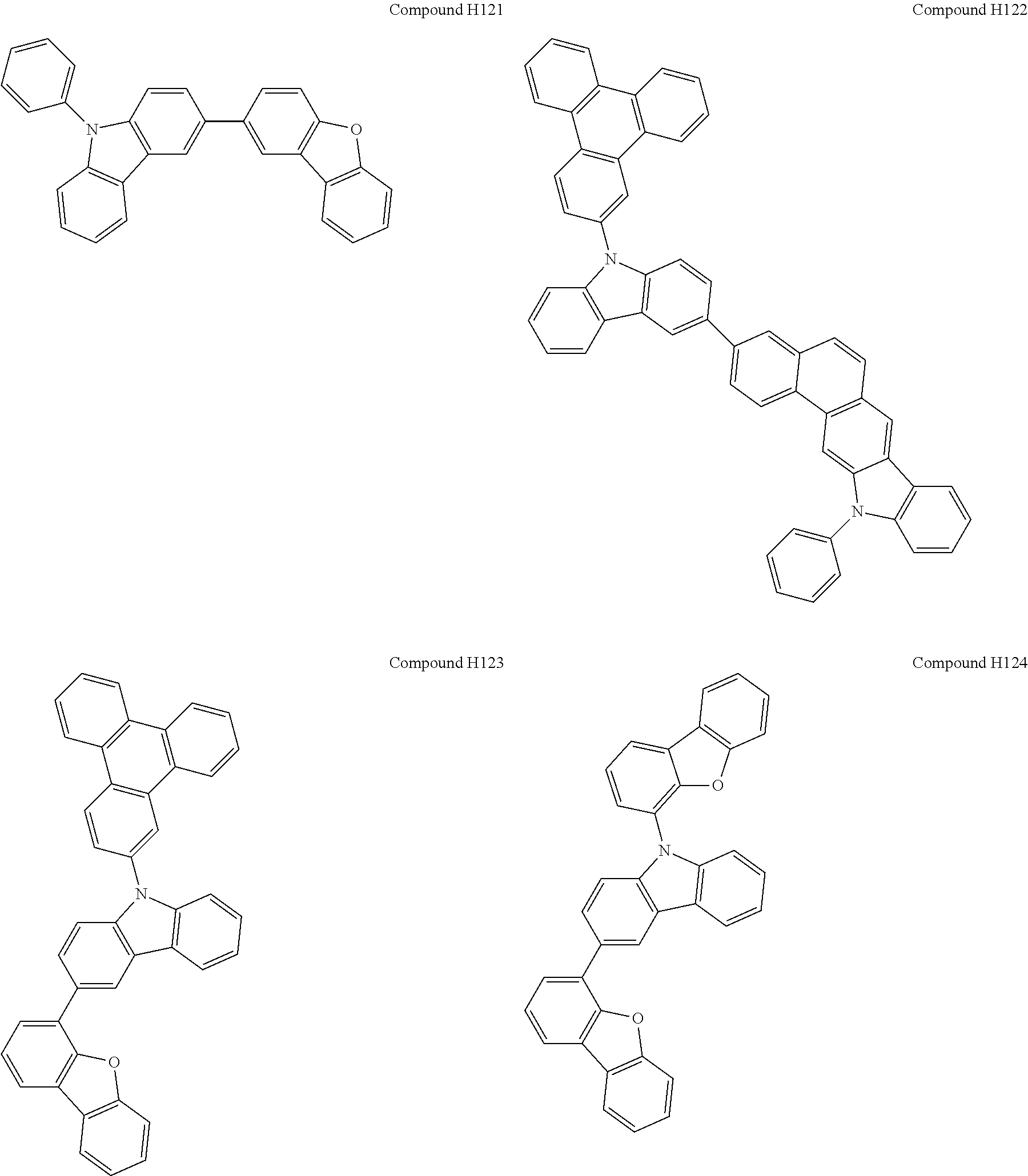


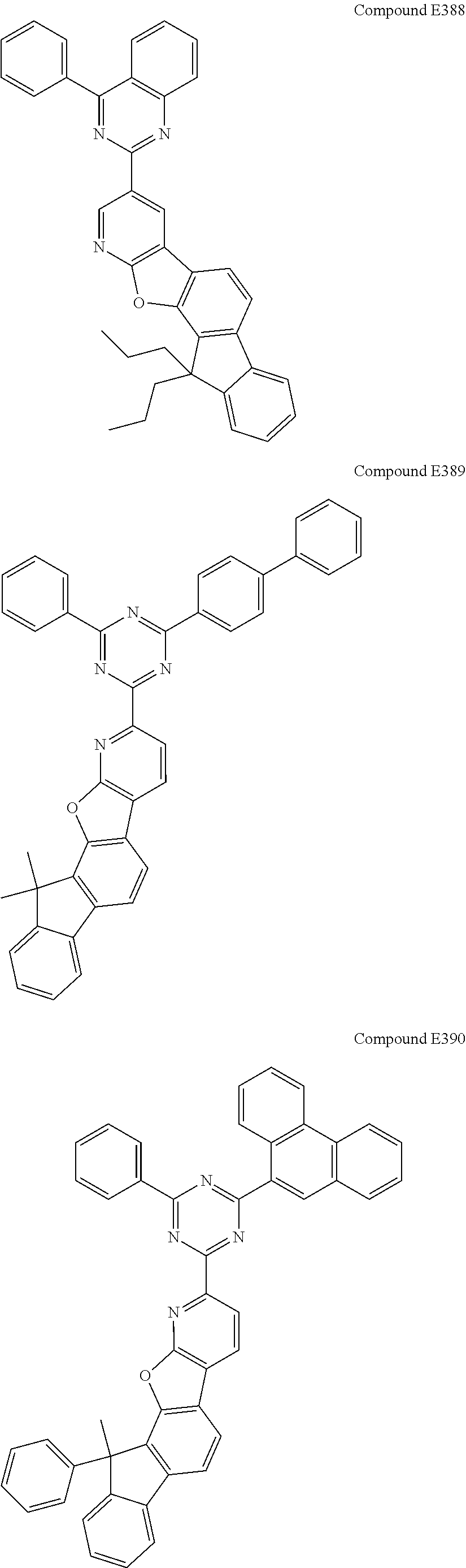


HAr3—(L)n—HAr4 (2)


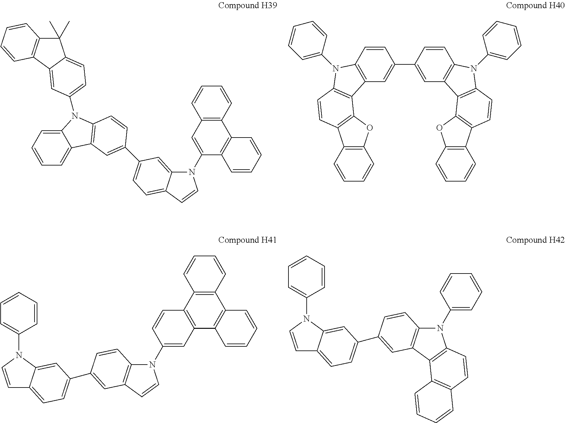


HAr1—(L)n—HAr2 (1)


HAr1—(L)n—HAr2 (1)


Applications Claiming Priority (4)
| Application Number | Priority Date | Filing Date | Title |
|---|---|---|---|
| KR20160006142 | 2016-01-18 | ||
| KR10-2016-0006142 | 2016-01-18 | ||
| KR1020160133381A KR20170086397A (en) | 2016-01-18 | 2016-10-14 | Organic light-emitting compounds and Organic light-emitting device comprising the same |
| KR10-2016-0133381 | 2016-10-14 |
Publications (2)
| Publication Number | Publication Date |
|---|---|
| US20170207397A1 US20170207397A1 (en) | 2017-07-20 |
| US11075343B2 true US11075343B2 (en) | 2021-07-27 |
Family
ID=59315156
Family Applications (1)
| Application Number | Title | Priority Date | Filing Date |
|---|---|---|---|
| US15/405,766 Active US11075343B2 (en) | 2016-01-18 | 2017-01-13 | Organic light emitting compounds and organic light emitting devices including the same |
Country Status (3)
| Country | Link |
|---|---|
| US (1) | US11075343B2 (en) |
| KR (1) | KR102582043B1 (en) |
| CN (1) | CN106977497B (en) |
Families Citing this family (23)
| Publication number | Priority date | Publication date | Assignee | Title |
|---|---|---|---|---|
| KR101928934B1 (en) * | 2016-02-23 | 2018-12-13 | 주식회사 엘지화학 | Hetero-cyclic compound and organic light emitting device comprising the same |
| US10957865B2 (en) * | 2016-07-27 | 2021-03-23 | Sfc Co., Ltd. | Organic light emitting compound and organic light emitting diode including the same |
| KR102506419B1 (en) * | 2017-07-13 | 2023-03-07 | 솔루스첨단소재 주식회사 | Organic compound and organic electroluminescent device comprising the same |
| KR102393153B1 (en) * | 2017-07-27 | 2022-05-02 | 에스에프씨주식회사 | organic light-emitting diode with high efficiency, low voltage and long lifetime |
| CN107501302A (en) * | 2017-08-11 | 2017-12-22 | 长春海谱润斯科技有限公司 | A kind of 1,3,5 pyrrolotriazine derivatives and its application |
| KR102418440B1 (en) * | 2017-09-29 | 2022-07-07 | 덕산네오룩스 주식회사 | Compound for organic electronic element, organic electronic element using the same, and an electronic device thereof |
| CN109928962A (en) * | 2017-12-18 | 2019-06-25 | 江苏三月光电科技有限公司 | It is a kind of using carbazole as the compound of core, preparation method and its application on organic electroluminescence device |
| KR102163072B1 (en) * | 2017-12-27 | 2020-10-07 | 주식회사 엘지화학 | Organic light emitting device |
| TWI811290B (en) * | 2018-01-25 | 2023-08-11 | 德商麥克專利有限公司 | Materials for organic electroluminescent devices |
| KR20200011873A (en) * | 2018-07-25 | 2020-02-04 | 롬엔드하스전자재료코리아유한회사 | Organic electroluminescent compound and organic electroluminescent device comprising the same |
| KR102341241B1 (en) * | 2018-11-23 | 2021-12-20 | 주식회사 엘지화학 | Novel compound and organic light emitting device comprising the same |
| US11296282B2 (en) * | 2018-12-17 | 2022-04-05 | Luminescence Technology Corp. | Organic compound and organic electroluminescence device using the same |
| US11108001B2 (en) * | 2019-01-17 | 2021-08-31 | Luminescence Technology Corp. | Organic compound and organic electroluminescence device using the same |
| CN110845483B (en) * | 2019-11-29 | 2021-11-16 | 武汉天马微电子有限公司 | Compound and application thereof |
| CN114456155B (en) * | 2020-11-09 | 2024-04-12 | 江苏三月科技股份有限公司 | Compound with azabenzene as core and application thereof |
| CN113651826B (en) * | 2020-12-11 | 2023-07-25 | 陕西莱特光电材料股份有限公司 | Nitrogen-containing compound, and electronic element and electronic device using same |
| JP2022108268A (en) * | 2021-01-12 | 2022-07-25 | 保土谷化学工業株式会社 | Organic thin film used for photoelectric conversion element, and photoelectric conversion element thereof |
| KR20220166622A (en) * | 2021-06-10 | 2022-12-19 | 주식회사 엘지화학 | Novel compound and organic light emitting device comprising the same |
| WO2023277446A1 (en) * | 2021-07-02 | 2023-01-05 | 엘티소재주식회사 | Heterocyclic compound, organic light-emitting device comprising same, and composition for organic layer |
| PT4426434T (en) | 2021-11-02 | 2025-11-24 | Flare Therapeutics Inc | Pparg inverse agonists and uses thereof |
| CN116209291A (en) * | 2023-01-13 | 2023-06-02 | 长春海谱润斯科技股份有限公司 | Application of carbazole derivative in organic electroluminescent device cover layer |
| CN119060021B (en) * | 2024-11-06 | 2025-02-18 | 安徽秀朗新材料科技有限公司 | A method for preparing asymmetric triazine compounds for OLED |
| CN120097973B (en) * | 2025-05-07 | 2025-07-15 | 江苏隆创光电材料有限公司 | Organic electroluminescent compound, electroluminescent material and electroluminescent device thereof |
Citations (11)
| Publication number | Priority date | Publication date | Assignee | Title |
|---|---|---|---|---|
| CN102056899A (en) | 2008-06-05 | 2011-05-11 | 出光兴产株式会社 | Polycyclic compound and organic electroluminescent device using same |
| KR20140025271A (en) | 2012-08-21 | 2014-03-04 | 제일모직주식회사 | Compound for organic optoelectronic device, organic light emitting diode including the same and display including the organic light emitting diode |
| WO2015090504A2 (en) | 2013-12-19 | 2015-06-25 | Merck Patent Gmbh | Heterocyclic spiro compounds |
| CN104795503A (en) | 2014-01-16 | 2015-07-22 | 三星显示有限公司 | Organic light-emitting device |
| KR20150111271A (en) | 2014-03-24 | 2015-10-05 | 주식회사 엠비케이 | New organic electroluminescent compounds and organic electroluminescent device comprising the same |
| KR20150141045A (en) | 2014-06-09 | 2015-12-17 | 주식회사 두산 | Organic electro luminescence device |
| US20160141522A1 (en) * | 2014-11-10 | 2016-05-19 | Universal Display Corporation | Organic Electroluminescent Materials and Devices |
| WO2017006181A1 (en) * | 2015-07-06 | 2017-01-12 | HO, Yin Yee Clara | Methods and system in user service enhancement for roaming in wireless mesh networks |
| US20170117486A1 (en) * | 2015-10-27 | 2017-04-27 | Samsung Display Co., Ltd. | Organic light-emitting device |
| KR20170056431A (en) | 2015-11-13 | 2017-05-23 | 에스에프씨 주식회사 | Novel heterocyclic compound and organic light-emitting diode including the same |
| US20180287073A1 (en) * | 2015-10-07 | 2018-10-04 | Lg Chem, Ltd. | Double spiro-type compound and organic light emitting diode comprising same |
Family Cites Families (2)
| Publication number | Priority date | Publication date | Assignee | Title |
|---|---|---|---|---|
| KR101486561B1 (en) * | 2010-12-31 | 2015-01-26 | 제일모직 주식회사 | Compound for organic photoelectric device and organic photoelectric device including the same |
| KR102630643B1 (en) * | 2015-05-27 | 2024-01-31 | 삼성디스플레이 주식회사 | Organic light-emitting device |
-
2017
- 2017-01-13 US US15/405,766 patent/US11075343B2/en active Active
- 2017-01-17 CN CN201710031627.7A patent/CN106977497B/en active Active
-
2022
- 2022-01-28 KR KR1020220012842A patent/KR102582043B1/en active Active
Patent Citations (13)
| Publication number | Priority date | Publication date | Assignee | Title |
|---|---|---|---|---|
| CN102056899A (en) | 2008-06-05 | 2011-05-11 | 出光兴产株式会社 | Polycyclic compound and organic electroluminescent device using same |
| KR20140025271A (en) | 2012-08-21 | 2014-03-04 | 제일모직주식회사 | Compound for organic optoelectronic device, organic light emitting diode including the same and display including the organic light emitting diode |
| CN104583202A (en) | 2012-08-21 | 2015-04-29 | 第一毛织株式会社 | Compound for organic photoelectronic device, organic light-emitting diode including same, and display device including organic light-emitting diode |
| US20150144938A1 (en) * | 2012-08-21 | 2015-05-28 | Samsung Sdi Co., Ltd. | Compound for organic optoelectronic device, organic light emitting diode including the same and display including the organic light emitting diode |
| WO2015090504A2 (en) | 2013-12-19 | 2015-06-25 | Merck Patent Gmbh | Heterocyclic spiro compounds |
| CN104795503A (en) | 2014-01-16 | 2015-07-22 | 三星显示有限公司 | Organic light-emitting device |
| KR20150111271A (en) | 2014-03-24 | 2015-10-05 | 주식회사 엠비케이 | New organic electroluminescent compounds and organic electroluminescent device comprising the same |
| KR20150141045A (en) | 2014-06-09 | 2015-12-17 | 주식회사 두산 | Organic electro luminescence device |
| US20160141522A1 (en) * | 2014-11-10 | 2016-05-19 | Universal Display Corporation | Organic Electroluminescent Materials and Devices |
| WO2017006181A1 (en) * | 2015-07-06 | 2017-01-12 | HO, Yin Yee Clara | Methods and system in user service enhancement for roaming in wireless mesh networks |
| US20180287073A1 (en) * | 2015-10-07 | 2018-10-04 | Lg Chem, Ltd. | Double spiro-type compound and organic light emitting diode comprising same |
| US20170117486A1 (en) * | 2015-10-27 | 2017-04-27 | Samsung Display Co., Ltd. | Organic light-emitting device |
| KR20170056431A (en) | 2015-11-13 | 2017-05-23 | 에스에프씨 주식회사 | Novel heterocyclic compound and organic light-emitting diode including the same |
Non-Patent Citations (2)
| Title |
|---|
| Chinese Office Action dated Mar. 19, 2019 in counterpart Chinese Patent Application No. 201710031627.7 (13 pages in English and 11 pages in Chinese). |
| Korean Office Action dated Mar. 11, 2021 in counterpart Korean Patent Application No. 10-2016-0133381 (13 pages in Korean). |
Also Published As
| Publication number | Publication date |
|---|---|
| US20170207397A1 (en) | 2017-07-20 |
| CN106977497B (en) | 2020-07-24 |
| CN106977497A (en) | 2017-07-25 |
| KR102582043B1 (en) | 2023-09-22 |
| KR20220020855A (en) | 2022-02-21 |
Similar Documents
| Publication | Publication Date | Title |
|---|---|---|
| US11075343B2 (en) | Organic light emitting compounds and organic light emitting devices including the same | |
| US11476426B2 (en) | Organic light emitting compounds and organic light emitting devices including the same | |
| US11545629B2 (en) | Organic light-emitting diode with high efficiency and low voltage | |
| US10947449B2 (en) | Organic light-emitting diode with high efficiency and long lifetime | |
| US10790450B2 (en) | Organic light-emitting diode with high efficiency and long lifetime | |
| US10741768B2 (en) | Organic light-emitting diode with high efficiency | |
| US11672172B2 (en) | Heterocyclic compound comprising aromatic amine group and organic light-emitting diode including the same | |
| US10468603B2 (en) | Organic light-emitting diode having low driving voltage and long lifespan | |
| US10014479B2 (en) | Organic light-emitting diode with high efficiency and long lifetime | |
| US11251378B2 (en) | Organic light-emitting diode having alleviated luminance reduction in low dynamic range | |
| US11404647B2 (en) | Organic compound for organic light emitting diode and organic light emitting diode including same | |
| US10957865B2 (en) | Organic light emitting compound and organic light emitting diode including the same | |
| US20190140177A1 (en) | Amine-substituted naphthalene derivatives and organic light emitting diodes including the same | |
| US12284917B2 (en) | Compound for organic light-emitting diode and organic light-emitting diode comprising same | |
| US12565509B2 (en) | Polycyclic aromatic derivative compound and organic light-emitting device using same | |
| US10529461B2 (en) | Heterocyclic compounds and organic light-emitting diode including the same | |
| US11532792B2 (en) | Organic light emitting diode having high efficiency | |
| US11279693B2 (en) | Organic heterocyclic compound and light-emitting diode comprising same | |
| US20220271225A1 (en) | Organic electroluminescent compounds and organic electroluminescent device | |
| US20200176695A1 (en) | Organic light-emitting diode with High efficiency and low voltage | |
| US20220006013A1 (en) | Organoelectroluminescent device using polycyclic aromatic compounds | |
| US20210305514A1 (en) | Polycyclic aromatic compound and organoelectroluminescent device using the same | |
| US12428429B2 (en) | Amine compound and organic light-emitting diode including same | |
| US20230276706A1 (en) | Novel heterocyclic compound and light-emitting diode including same | |
| US12410199B2 (en) | Organic light emitting compound and organic light emitting device |
Legal Events
| Date | Code | Title | Description |
|---|---|---|---|
| AS | Assignment |
Owner name: SFC CO., LTD., KOREA, REPUBLIC OF Free format text: ASSIGNMENT OF ASSIGNORS INTEREST;ASSIGNORS:LEE, SE-JIN;YU, TAEJUNG;PARK, SEOK-BAE;AND OTHERS;REEL/FRAME:040973/0213 Effective date: 20170113 |
|
| STPP | Information on status: patent application and granting procedure in general |
Free format text: DOCKETED NEW CASE - READY FOR EXAMINATION |
|
| STPP | Information on status: patent application and granting procedure in general |
Free format text: NON FINAL ACTION MAILED |
|
| STPP | Information on status: patent application and granting procedure in general |
Free format text: RESPONSE TO NON-FINAL OFFICE ACTION ENTERED AND FORWARDED TO EXAMINER |
|
| STPP | Information on status: patent application and granting procedure in general |
Free format text: FINAL REJECTION MAILED |
|
| STPP | Information on status: patent application and granting procedure in general |
Free format text: RESPONSE AFTER FINAL ACTION FORWARDED TO EXAMINER |
|
| STPP | Information on status: patent application and granting procedure in general |
Free format text: DOCKETED NEW CASE - READY FOR EXAMINATION |
|
| STPP | Information on status: patent application and granting procedure in general |
Free format text: NON FINAL ACTION MAILED |
|
| STPP | Information on status: patent application and granting procedure in general |
Free format text: RESPONSE TO NON-FINAL OFFICE ACTION ENTERED AND FORWARDED TO EXAMINER |
|
| STPP | Information on status: patent application and granting procedure in general |
Free format text: FINAL REJECTION MAILED |
|
| STPP | Information on status: patent application and granting procedure in general |
Free format text: DOCKETED NEW CASE - READY FOR EXAMINATION |
|
| STPP | Information on status: patent application and granting procedure in general |
Free format text: DOCKETED NEW CASE - READY FOR EXAMINATION |
|
| STPP | Information on status: patent application and granting procedure in general |
Free format text: NOTICE OF ALLOWANCE MAILED -- APPLICATION RECEIVED IN OFFICE OF PUBLICATIONS |
|
| STPP | Information on status: patent application and granting procedure in general |
Free format text: AWAITING TC RESP., ISSUE FEE NOT PAID |
|
| STPP | Information on status: patent application and granting procedure in general |
Free format text: NOTICE OF ALLOWANCE MAILED -- APPLICATION RECEIVED IN OFFICE OF PUBLICATIONS |
|
| STPP | Information on status: patent application and granting procedure in general |
Free format text: PUBLICATIONS -- ISSUE FEE PAYMENT RECEIVED |
|
| STPP | Information on status: patent application and granting procedure in general |
Free format text: PUBLICATIONS -- ISSUE FEE PAYMENT VERIFIED |
|
| STCF | Information on status: patent grant |
Free format text: PATENTED CASE |
|
| MAFP | Maintenance fee payment |
Free format text: PAYMENT OF MAINTENANCE FEE, 4TH YR, SMALL ENTITY (ORIGINAL EVENT CODE: M2551); ENTITY STATUS OF PATENT OWNER: SMALL ENTITY Year of fee payment: 4 |