US11074889B2 - Adaptive compression by light level - Google Patents
Adaptive compression by light level Download PDFInfo
- Publication number
- US11074889B2 US11074889B2 US16/614,784 US201816614784A US11074889B2 US 11074889 B2 US11074889 B2 US 11074889B2 US 201816614784 A US201816614784 A US 201816614784A US 11074889 B2 US11074889 B2 US 11074889B2
- Authority
- US
- United States
- Prior art keywords
- display data
- display
- brightness
- light
- reducing
- Prior art date
- Legal status (The legal status is an assumption and is not a legal conclusion. Google has not performed a legal analysis and makes no representation as to the accuracy of the status listed.)
- Active
Links
Images


Classifications
-
- H—ELECTRICITY
- H04—ELECTRIC COMMUNICATION TECHNIQUE
- H04N—PICTORIAL COMMUNICATION, e.g. TELEVISION
- H04N9/00—Details of colour television systems
- H04N9/77—Circuits for processing the brightness signal and the chrominance signal relative to each other, e.g. adjusting the phase of the brightness signal relative to the colour signal, correcting differential gain or differential phase
-
- H—ELECTRICITY
- H04—ELECTRIC COMMUNICATION TECHNIQUE
- H04N—PICTORIAL COMMUNICATION, e.g. TELEVISION
- H04N5/00—Details of television systems
- H04N5/44—Receiver circuitry for the reception of television signals according to analogue transmission standards
- H04N5/57—Control of contrast or brightness
- H04N5/58—Control of contrast or brightness in dependence upon ambient light
-
- G—PHYSICS
- G09—EDUCATION; CRYPTOGRAPHY; DISPLAY; ADVERTISING; SEALS
- G09G—ARRANGEMENTS OR CIRCUITS FOR CONTROL OF INDICATING DEVICES USING STATIC MEANS TO PRESENT VARIABLE INFORMATION
- G09G5/00—Control arrangements or circuits for visual indicators common to cathode-ray tube indicators and other visual indicators
- G09G5/10—Intensity circuits
-
- G—PHYSICS
- G02—OPTICS
- G02B—OPTICAL ELEMENTS, SYSTEMS OR APPARATUS
- G02B27/00—Optical systems or apparatus not provided for by any of the groups G02B1/00 - G02B26/00, G02B30/00
- G02B27/01—Head-up displays
- G02B27/017—Head mounted
-
- G—PHYSICS
- G06—COMPUTING OR CALCULATING; COUNTING
- G06F—ELECTRIC DIGITAL DATA PROCESSING
- G06F3/00—Input arrangements for transferring data to be processed into a form capable of being handled by the computer; Output arrangements for transferring data from processing unit to output unit, e.g. interface arrangements
- G06F3/01—Input arrangements or combined input and output arrangements for interaction between user and computer
- G06F3/011—Arrangements for interaction with the human body, e.g. for user immersion in virtual reality
- G06F3/013—Eye tracking input arrangements
-
- G—PHYSICS
- G09—EDUCATION; CRYPTOGRAPHY; DISPLAY; ADVERTISING; SEALS
- G09G—ARRANGEMENTS OR CIRCUITS FOR CONTROL OF INDICATING DEVICES USING STATIC MEANS TO PRESENT VARIABLE INFORMATION
- G09G3/00—Control arrangements or circuits, of interest only in connection with visual indicators other than cathode-ray tubes
- G09G3/20—Control arrangements or circuits, of interest only in connection with visual indicators other than cathode-ray tubes for presentation of an assembly of a number of characters, e.g. a page, by composing the assembly by combination of individual elements arranged in a matrix no fixed position being assigned to or needed to be assigned to the individual characters or partial characters
- G09G3/2003—Display of colours
-
- G—PHYSICS
- G09—EDUCATION; CRYPTOGRAPHY; DISPLAY; ADVERTISING; SEALS
- G09G—ARRANGEMENTS OR CIRCUITS FOR CONTROL OF INDICATING DEVICES USING STATIC MEANS TO PRESENT VARIABLE INFORMATION
- G09G5/00—Control arrangements or circuits for visual indicators common to cathode-ray tube indicators and other visual indicators
- G09G5/02—Control arrangements or circuits for visual indicators common to cathode-ray tube indicators and other visual indicators characterised by the way in which colour is displayed
-
- H—ELECTRICITY
- H04—ELECTRIC COMMUNICATION TECHNIQUE
- H04N—PICTORIAL COMMUNICATION, e.g. TELEVISION
- H04N9/00—Details of colour television systems
- H04N9/64—Circuits for processing colour signals
-
- G—PHYSICS
- G09—EDUCATION; CRYPTOGRAPHY; DISPLAY; ADVERTISING; SEALS
- G09G—ARRANGEMENTS OR CIRCUITS FOR CONTROL OF INDICATING DEVICES USING STATIC MEANS TO PRESENT VARIABLE INFORMATION
- G09G2320/00—Control of display operating conditions
- G09G2320/06—Adjustment of display parameters
- G09G2320/0626—Adjustment of display parameters for control of overall brightness
-
- G—PHYSICS
- G09—EDUCATION; CRYPTOGRAPHY; DISPLAY; ADVERTISING; SEALS
- G09G—ARRANGEMENTS OR CIRCUITS FOR CONTROL OF INDICATING DEVICES USING STATIC MEANS TO PRESENT VARIABLE INFORMATION
- G09G2320/00—Control of display operating conditions
- G09G2320/06—Adjustment of display parameters
- G09G2320/0666—Adjustment of display parameters for control of colour parameters, e.g. colour temperature
-
- G—PHYSICS
- G09—EDUCATION; CRYPTOGRAPHY; DISPLAY; ADVERTISING; SEALS
- G09G—ARRANGEMENTS OR CIRCUITS FOR CONTROL OF INDICATING DEVICES USING STATIC MEANS TO PRESENT VARIABLE INFORMATION
- G09G2330/00—Aspects of power supply; Aspects of display protection and defect management
- G09G2330/02—Details of power systems and of start or stop of display operation
- G09G2330/021—Power management, e.g. power saving
-
- G—PHYSICS
- G09—EDUCATION; CRYPTOGRAPHY; DISPLAY; ADVERTISING; SEALS
- G09G—ARRANGEMENTS OR CIRCUITS FOR CONTROL OF INDICATING DEVICES USING STATIC MEANS TO PRESENT VARIABLE INFORMATION
- G09G2340/00—Aspects of display data processing
- G09G2340/02—Handling of images in compressed format, e.g. JPEG, MPEG
-
- G—PHYSICS
- G09—EDUCATION; CRYPTOGRAPHY; DISPLAY; ADVERTISING; SEALS
- G09G—ARRANGEMENTS OR CIRCUITS FOR CONTROL OF INDICATING DEVICES USING STATIC MEANS TO PRESENT VARIABLE INFORMATION
- G09G2340/00—Aspects of display data processing
- G09G2340/04—Changes in size, position or resolution of an image
- G09G2340/0407—Resolution change, inclusive of the use of different resolutions for different screen areas
- G09G2340/0428—Gradation resolution change
-
- G—PHYSICS
- G09—EDUCATION; CRYPTOGRAPHY; DISPLAY; ADVERTISING; SEALS
- G09G—ARRANGEMENTS OR CIRCUITS FOR CONTROL OF INDICATING DEVICES USING STATIC MEANS TO PRESENT VARIABLE INFORMATION
- G09G2340/00—Aspects of display data processing
- G09G2340/04—Changes in size, position or resolution of an image
- G09G2340/0407—Resolution change, inclusive of the use of different resolutions for different screen areas
- G09G2340/0435—Change or adaptation of the frame rate of the video stream
-
- G—PHYSICS
- G09—EDUCATION; CRYPTOGRAPHY; DISPLAY; ADVERTISING; SEALS
- G09G—ARRANGEMENTS OR CIRCUITS FOR CONTROL OF INDICATING DEVICES USING STATIC MEANS TO PRESENT VARIABLE INFORMATION
- G09G2350/00—Solving problems of bandwidth in display systems
-
- G—PHYSICS
- G09—EDUCATION; CRYPTOGRAPHY; DISPLAY; ADVERTISING; SEALS
- G09G—ARRANGEMENTS OR CIRCUITS FOR CONTROL OF INDICATING DEVICES USING STATIC MEANS TO PRESENT VARIABLE INFORMATION
- G09G2360/00—Aspects of the architecture of display systems
- G09G2360/14—Detecting light within display terminals, e.g. using a single or a plurality of photosensors
- G09G2360/141—Detecting light within display terminals, e.g. using a single or a plurality of photosensors the light conveying information used for selecting or modulating the light emitting or modulating element
-
- G—PHYSICS
- G09—EDUCATION; CRYPTOGRAPHY; DISPLAY; ADVERTISING; SEALS
- G09G—ARRANGEMENTS OR CIRCUITS FOR CONTROL OF INDICATING DEVICES USING STATIC MEANS TO PRESENT VARIABLE INFORMATION
- G09G2360/00—Aspects of the architecture of display systems
- G09G2360/14—Detecting light within display terminals, e.g. using a single or a plurality of photosensors
- G09G2360/144—Detecting light within display terminals, e.g. using a single or a plurality of photosensors the light being ambient light
-
- G—PHYSICS
- G09—EDUCATION; CRYPTOGRAPHY; DISPLAY; ADVERTISING; SEALS
- G09G—ARRANGEMENTS OR CIRCUITS FOR CONTROL OF INDICATING DEVICES USING STATIC MEANS TO PRESENT VARIABLE INFORMATION
- G09G2360/00—Aspects of the architecture of display systems
- G09G2360/14—Detecting light within display terminals, e.g. using a single or a plurality of photosensors
- G09G2360/145—Detecting light within display terminals, e.g. using a single or a plurality of photosensors the light originating from the display screen
-
- G—PHYSICS
- G09—EDUCATION; CRYPTOGRAPHY; DISPLAY; ADVERTISING; SEALS
- G09G—ARRANGEMENTS OR CIRCUITS FOR CONTROL OF INDICATING DEVICES USING STATIC MEANS TO PRESENT VARIABLE INFORMATION
- G09G2360/00—Aspects of the architecture of display systems
- G09G2360/16—Calculation or use of calculated indices related to luminance levels in display data
Definitions
- the present invention tries to reduce the amount of display data that needs to be sent for display to try to mitigate the above problems.
- the invention provides a method for adapting display data forming an image for display on a display screen to a viewer, the method comprising:
- the method further comprises compressing the adjusted display data prior to sending the adjusted display data for display on the display screen.
- adjusting the at least one display value excludes adjusting a luminance value of the display data.
- the one or more predetermined parameters are preferably based on a predetermined model of reactions of a human eye to light or changes in light.
- Monitoring the light may comprise monitoring light emitted or to be emitted by the display screen when the image is displayed thereon, for example by determining a luminance of the display data being displayed or to be displayed on the display screen, and/or monitoring the light may comprise monitoring ambient light in the vicinity of the viewer.
- analysing the information based on one or more predetermined parameters comprises comparing a level of brightness of the monitored light to one or more brightness thresholds.
- the one or more thresholds preferably includes a first brightness threshold, and adjusting the at least one display value preferably comprises, when the monitored level of brightness is below the first brightness threshold, performing one or more of:
- the one or more thresholds includes a second brightness threshold
- adjusting the at least one display value comprises, when the monitored level of brightness of the light is above the second brightness threshold, performing one or more of:
- the one or more thresholds includes a third brightness threshold
- adjusting the at least one display value comprises, when the monitored level of brightness remains below the third brightness threshold for a first predetermined period of time, performing one or more of:
- Adjusting the at least one display value may optionally comprise reducing values of blue and/or green colour components of the display data when the monitored level of brightness remains below the third brightness threshold for a second predetermined period of time, and/or may comprise removing all colour data of the display data when the monitored level of brightness remains below the third brightness threshold for a third predetermined period of time.
- Reducing a luminance depth of at least a portion of the display data may optionally comprise relatively reducing a luminance depth of a portion of the display data forming part of the image compared to a luminance depth of a portion of the display data forming a different part of the image.
- the method may further comprise receiving feedback from an eye tracking sensor as to which part of the image is being focussed on by the viewer, and relatively reducing the luminance depth of the part of the image being focussed on by the viewer and relatively increasing the luminance depth of a different part of the image which is being viewed using peripheral vision of the viewer.
- the one or more thresholds includes a fourth brightness threshold
- the method further comprises comparing the monitored level of brightness with recent previous levels of brightness and adjusting the at least one display value comprises, when the monitored level of brightness has increased by at least a predetermined amount from the recent previous levels of brightness to a brightness level above the fourth brightness threshold, performing one or more of:
- adjusting the at least one display value may optionally comprise performing one or more of:
- the one or more predetermined parameters may include one or more colour thresholds and monitoring the light may comprise monitoring relative levels of different colour components in the monitored light. Monitoring the light may further comprise determining a level of red colour component in the monitored light relative to other colour components in the monitored light, and wherein adjusting the at least one display value comprises, when the determined level of red colour component in the monitored light relative to other colour components in the light is above a first red colour threshold, performing one or more of:
- Increasing a luminance depth of at least a portion of the display data preferably optionally comprises relatively increasing a luminance depth of a portion of the display data forming part of the image compared to a luminance depth of a portion of the display data forming a different part of the image.
- the method my further optionally include receiving feedback from an eye tracking sensor as to which part of the image is being focussed on by the viewer, and relatively decreasing the luminance range of the part of the image being focussed on by the viewer and relatively increasing a different part of the image which is being viewed using peripheral vision of the viewer
- Monitoring the light may comprise monitoring the light with a photo detector or with a camera.
- the display screen may be at an augmented reality device or virtual reality headset.
- the invention provides an apparatus configured to perform method described above.
- the invention provides a system comprising an apparatus as described above and an augmented reality device or virtual reality headset comprising the display screen.
- the invention provides a method of taking light adaptation of the photoreceptors in a user's eyes into account when generating and transmitting display data, comprising:
- Amending the generated display data may involve removing elements such as colour depth, fast movement, and details requiring high acuity, reducing the volume of data being transmitted across a limited-bandwidth connection.
- the light level may be determined from knowledge of the display data being transmitted or having been transmitted, or it may be determined from a light measurement device in the vicinity of the viewer which detects the overall luminance of the displayed display data plus ambient light level and colour balance.
- control of the ambient light level prior to the beginning of transmission of display data may be used in order to acclimatise the user's eyes to a lower light level of the intended display images.
- the ambient light could be changed from a more conventional white light to a red light in order to allow the user's eyes to transition to a level of Scotopic vision without removing ambient light entirely. Total darkness could subsequently be used for a shorter period to ensure total dark adaptation. Red light could also be used to enable illumination suitable for Photopic vision while also maintaining some level of Scotopic vision.
- the continual adjustment to the display data to match the actual visibility of the images presented to the viewer can be used to reduce the overall data volume transmitted. This in turn reduces the bandwidth demands on the communication path and also save power
- FIG. 1 shows the changing sensitivity of different retinal receptors during dark adaptation
- FIG. 2 shows the changing sensitivity of different retinal receptors during light adaptation
- FIG. 3 shows one embodiment of a system according to the invention
- FIG. 4 shows an embodiment of the system with an external light measurement device
- FIG. 5 shows an embodiment of the system which is contained in a single device
- FIG. 6 shows an embodiment of the system with an internal light measurement device
- FIG. 7 shows an embodiment of the system which is contained in a large space
- FIG. 8 shows a flow chart of a method according to an embodiment of the invention.
- FIG. 9 shows a more detailed example system, with a model eye
- FIG. 10 shows a more detailed example decision-making process
- FIG. 11 shows a second detailed example system using a multi-purpose programmable processor
- FIG. 12 shows several further detailed example decision-making processes
- FIG. 13 shows an example system with a single threshold
- FIG. 14 shows the decision-making process associated with the embodiment in FIG. 11 ;
- FIG. 15 shows a frame with areas of contrasting luminance.
- the cones are mostly active in normal lighting, such as daylight or ambient indoor lighting. This provides what is known as Photopic vision, which includes full colour range, responsiveness to small, fast movements, and greatest sensitivity in the foveal area of the eye as this is where the cones are most concentrated.
- the rods are more active and Photopic vision gives way to Scotopic vision. This is characterised by monochrome vision, low responsiveness to small, fast movements, and greatest sensitivity in the area outside the fovea.
- both types of vision can be used, allowing high acuity from the cones while preserving the sensitivity of the rods. This also allows illumination to be provided while preserving the chemical changes that occur in the photoreceptors during the transition between Photopic and Scotopic vision.
- the so-called Pukinje effect or “blue shift” may occur.
- the peak luminance sensitivity of the human eye shifts towards the blue-green end of the spectrum.
- This effect introduces a variation in contrast under different levels of illumination. It occurs because the cones are sensitive to red, green and blue light but require higher levels of illumination to stimulate them than the rods.
- the rods cannot discriminate colour but are more sensitive at low light levels than cones and have the greatest response to light in the blue-green end of the spectrum. As the light intensity reduces the cones are stimulated less, washing out most of the perceived colour.
- the objects emitting or reflecting blue-green wavelengths appear relatively brighter than objects emitting or reflecting light at the red end of the spectrum due to the sensitivity of the rods at the shorter (blue/green) wavelengths.
- FIG. 1 is a graph showing the decrease in the intensity of light required to activate the two primary photoreceptors in the human retina.
- the vertical axis shows the threshold intensity from a high threshold to a low threshold. This indicates the intensity of light required before the light is detected. The lower the threshold, the more sensitive the photoreceptor is.
- the horizontal axis shows the time spent in the dark in minutes, divided into units of ten minutes, which are indicated with vertical lines which intersect the curves showing the sensitivity of the photoreceptors.
- the solid line shows the sensitivity of the cones, which are used for colour vision.
- These photoreceptors are more sensitive in bright conditions, but they do not have a large range of sensitivity and so are less active in low light conditions.
- the sensitivity curve levels out after about ten minutes in darkness and there is negligible further improvement in sensitivity.
- the dotted line shows the sensitivity of the rods, which are used for monochrome and low-light vision. Naturally, they are capable of a much higher level of sensitivity, as is shown on the graph in FIG. 1 by the fact that this curve reaches a much lower threshold intensity—representing a lower level of brightness, or luminance, required for activating the rods and therefore higher sensitivity—than the curve showing the sensitivity of the cones.
- the rods are less sensitive than the cones after up to ten minutes in darkness, the level of luminance required to activate them continues to fall after the sensitivity of the cones has reached its maximum.
- the sensitivity of the rods does not level to a maximum until after approximately 30-40 minutes in darkness, as shown by the low level of the threshold luminance for the rods at this point.
- FIG. 2 shows the sensitivity of photoreceptors which have adapted to low light intensity as described in FIG. 1 . Specifically, it shows the increasing intensity of light required to activate the rods and cones: as described in FIG. 1 , the higher the threshold intensity as shown on the vertical axis, the greater the intensity of light required for activation of the appropriate photoreceptor.
- the solid line shows the sensitivity of the cones and the dashed line shows the sensitivity of the rods.
- An increase in luminance reverses the chemical changes generated as part of dark adaptation and will cause a change from Scotopic to Photopic vision in less than 5 minutes, regardless of the size of the increase, provided it is sufficient to activate the cones.
- the level of the luminance is shown on the horizontal axis. If the light is very bright, the user will be “dazzled” as his or her photoreceptors are overstimulated; as such, during the light adaptation period the photoreceptors will be less sensitive. This is shown by the sharp upwards curves shown in the Figure.
- Red light is an exception to this pattern; red light at higher than threshold luminance will have a reduced impact on dark adaptation of the rods but will stimulate the cones sufficiently for Photopic vision to return. This means that an eye which has been exposed to red light can be assumed to be dark adapted as if it has been exposed to an extremely low light level, so exposure to red light will significantly shorten the time required for full dark adaptation.
- FIG. 1 and FIG. 2 show chemical changes which are predictable and can therefore be modelled.
- the present invention is preferably based on such a model of the reactions of the eye to light within the system.
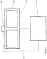
- FIG. 3 shows a virtual reality headset [ 31 ] connected to a host device [ 32 ], which may be a computing device, gaming station, etc.
- the virtual reality headset [ 31 ] incorporates two display panels [ 33 ], which may be embodied as a single panel split by optical elements. In use, one display is presented to each of a viewer's eyes.
- the host device [ 32 ] generates image data for display on these panels [ 33 ] and transmits the image data to the virtual reality headset [ 31 ].
- the host device [ 32 ] may determine, as it generates image data for transmission to the virtual reality headset [ 31 ], how bright the images will be. In general, if the images are below a certain threshold of luminance, the host device [ 32 ] then begins timing how long the luminance of the images being transmitted remains below that threshold (similarly, if the initial image data is below the threshold of luminance, the host device [ 32 ] would begin timing when the stream of image data is initialised). It might also immediately reduce colour depth and resolution to a minimum as the user will not be able to detect image detail.
- the host [ 32 ] could adjust the image data being sent to reduce the number of shades of colour compared to the number in the image data as generated; drop red and yellow components of the light transmitted to leave only the blue components in order to account for blue shift; and/or potentially finally drop the colour density entirely to monochrome after a further, longer period of time, e.g. forty minutes. Furthermore, the host [ 32 ] could also reduce the resolution of the image to a minimum after this time. If the colour depth and resolution were reduced to a minimum upon the luminance falling below the threshold, they might be restored to low levels after ten minutes in order to account for dark adaptation. The process would then continue as described.
- the host [ 32 ] can continue to send display data with very little colour information, or indeed detail in general, for a period of time commensurate to the period for which the luminance of the frames has been low. This is possible without affecting the quality of the images perceived by a user because after a long period of exposure to low-luminance images the user's photoreceptors will be at their most sensitive, as indicated by the adaption model of the eye, and they will therefore be overstimulated by a sudden increase in luminance, reducing his or her acuity and sensitivity to colour.
- the frame rate and colour quantisation may be gradually increased, again based on assumptions regarding light adaption as shown in FIG. 1 . This is necessary because a user will lose dark adaptation and his or her photoreceptors will no longer be overstimulated.
- the user could also be “pre-conditioned” by spending a known amount of time in a darkened or red-lit environment prior to putting on the virtual reality headset [ 31 ] and the display data transmitted for display could then be amended from the beginning rather than waiting for time to pass.
- the use of such a method could be indicated to the host [ 32 ] via an override signal, which will pre-configure an adaption model.
- FIG. 4 shows a second possible system.
- a host device [ 32 ] connected to a headset [ 41 ], but in this example the headset [ 41 ] is a set of augmented reality glasses.
- the headset [ 41 ] is a set of augmented reality glasses.
- an external light measurement device [ 42 ] attached to the glasses and connected to the host device [ 32 ] in order to measure such luminance.
- the host device [ 32 ] may be a static computing device such as a computer, gaming console, etc., or may be a mobile computing device such as a smartphone or smartwatch. As previously described, it generates image data and transmits it to the augmented reality glasses [ 41 ] for display.
- the light measurement device [ 42 ] is connected to the host device [ 32 ]. It acts as a sensor to detect the ambient light level, and transmits [ 44 ] this to the host device [ 32 ], which may then send data with a reduced colour gamut or resolution generally, as previously described.
- the data received [ 44 ] from the light measurement device [ 42 ] would be used in the same way as data collected on the luminance of the frames being transmitted to the display panels [ 33 ] in the virtual reality headset [ 31 ] described in FIG. 3 , possibly in combination with knowledge of the luminance of the generated frames as previously described.
- a camera pointed at the display panels [ 43 ] could act as a light measurement device, as this would provide actual knowledge of the light being presented to a user's eyes.
- a camera could be mounted on, for example, an arm of the glasses, or on the user's face near or even inside his or her eyes, for example as part of a contact lens.
- FIG. 5 shows a system which is similar in operation to the embodiment shown in FIG. 4 .
- the entire system is contained in a single casing [ 51 ], for example in a smartphone or other such mobile computing device.
- the device contains a processor [ 53 ], which generates display data for display on the integral display panel [ 52 ].
- the device [ 51 ] also has an external light measurement device [ 54 ], similar to that described in FIG. 4 . Since the device [ 51 ] will not be enclosed, ambient light will affect the dark adaptation of any user's eyes, and as in the system described in FIG. 4 , the external light measurement device [ 54 ] monitors the ambient luminance.
- a camera pointed at the display panel [ 52 ] could act as a light measurement device, as previously described with reference to FIG. 4 . In either case, the camera or light measurement device [ 54 ] transmits [ 55 ] this data to the processor [ 53 ], where it is used to adjust the image data transmitted to the display panel [ 52 ] as previously described.
- connection between the processor [ 53 ] and the display panel [ 52 ] is less likely to have a limited bandwidth compared to the connection between the host device [ 32 ] and either the virtual reality headset [ 31 ] described in FIG. 3 or the augmented reality glasses [ 41 ] described in FIG. 4 .
- FIG. 6 shows a further example of a system in which a virtual reality headset [ 61 ] is connected to a host device [ 32 ].
- the virtual reality headset [ 61 ] incorporates two display panels [ 62 ], one of which is presented to each of the user's eyes, and is itself likely to be sealed against ambient light when in use.
- the virtual reality headset [ 61 ] incorporates an internal light measurement device [ 63 ]. As previously described, this is connected to the host device [ 32 ], but unlike the light measurement device [ 42 ] described in FIG. 4 , it transmits data on the luminance within the virtual reality headset [ 61 ]. This will detect the combination of ambient light level actually present within the virtual reality headset [ 61 ] and the display such that, for example, if there are warning lights not controlled by the host [ 32 ], their use will still be detected. The light measurement device [ 63 ] then transmits [ 64 ] this information to the host [ 32 ], which can apply appropriate adjustments to the display data being transmitted to the display.
- a camera pointed at the display panels [ 62 ] could act as a light measurement device, as previously described with reference to FIG. 4 .
- this system also means that if it is not convenient to determine the luminance of frames as they are transmitted from the host [ 32 ], for example due to limited processing power in the transmitter or if the data is strongly encrypted, the described methods can still be used to amend the data as previously described during generation.
- FIG. 7 shows a system which is similar in operation to the system shown in FIG. 6 in that there is an enclosed area [ 61 / 71 ] containing a display device [ 62 / 72 ] and a light measurement device [ 63 / 73 ], and the user(s) [ 76 ] is/are viewing the display device [ 62 / 72 ] from within the enclosed area [ 61 / 71 ].
- the system is in a theatre setting, or similar environment such as a motion-simulator fairground ride.
- the display device [ 72 ] is a screen at the front of the environment [ 71 ]. It is being viewed by multiple users in an audience [ 76 ].
- the actual light level in the enclosed space [ 71 ] is detected by a light measurement device [ 73 ] and transmitted [ 75 ] to the host [ 74 ], and therefore if there is a change in the light level not controlled by the host [ 74 ] which is providing the display data for the display, such as a member of the audience [ 76 ] opening an exit door into a lit vestibule, the resulting changes in the audience's [ 76 ] dark adaptation can be accounted for. Since the chemical changes to the photoreceptors of the human eye are largely uniform across the population, it is likely that the eyes of all members of the audience [ 76 ] will adjust to lower light levels at the same rate.
- this embodiment could be used for a method in which the light level is controlled in order to manipulate the user's or users' [ 76 ] dark adaptation prior to showing display data.
- the enclosed area [ 71 ] is sealed against ambient light for a long period (up to forty minutes) prior to the beginning of transmission of display data by the host [ 74 ].
- the display data could then from the beginning be amended as previously described.
- the enclosed area [ 71 ] could be red-lit during this time in order to allow the users [ 76 ] to see enough to move around. This is possible due to the effects of red light on the photoreceptors described above, meaning that a user can move from red light to darkness and be assumed to be essentially dark adapted.
- the nature of the content to be transmitted as display data is known—for example, it is a pre-generated video clip, or a feed from a camera that only produces a particular type of display data—the time between the enclosed area [ 71 ] being sealed against ambient light and the beginning of transmission of display data could be adjusted accordingly. For example, if the audience [ 76 ] is to view a brightly-lit scene from a film on the display device [ 72 ], very little time elapses before display begins, but if the audience [ 76 ] is to view a projection of the night sky, which will be dim and monochrome, the full forty minutes may be allowed to elapse.
- FIG. 8 shows a flowchart of a generic version of the process followed, which will be described with reference to the embodiment shown in FIG. 3 , with deviations for the other embodiments described as appropriate.
- Step S 81 the next frame of display data is generated in the host [ 32 ] according to the operation of applications running on the host [ 32 ].
- the current or most recent light level is determined.
- the luminance may be determined using the luminance as detected by the light measurement devices [ 42 , 54 , 63 , 73 ], likely combined with the recent light level in a similar way to the luminance of a transmitted frame, and the output from the light measurement devices [ 42 , 54 , 63 , 73 ] may be used in conjunction with the luminance of frames.
- Step S 83 the amendment of the display data, may be subsequent to the generation of the display data in that data may be generated and then amended, perhaps improving the compression applied prior to transmission.
- the first two steps may be reversed so that the information generated at Step S 82 on light level may be fed directly into the processes generating the display data such that only appropriate display data is generated at all, in which case Steps 81 and 83 are combined.
- Step S 83 only the data which can be assumed to be most beneficial to any user viewing the images is prepared for transmission. This removes redundant data prior to the compression/transmission, improving efficiency.
- the display data can be presented at full colour depth and frame rate.
- a threshold say, less than five minutes
- foveal compression could also be used to reduce the quality of peripheral areas of the display without affecting user experience (naturally, if many people are viewing the same image, as in the embodiment in FIG. 7 , foveal compression would not be possible; it uses eye-tracking in order to determine the point of focus of a user). This is because any user will still be using Photopic vision and therefore will have high acuity and responsiveness to fast movement and will be able to see a full range of colour, and due to the distribution of photoreceptors the user's fovea will be the most sensitive area of the retina.
- a particular frame has a luminance below a threshold it can be amended to have a lower resolution and therefore less detail. This is possible because a user's eyes will not be sensitive enough in low light to see such detail; only the rods in the eye are being stimulated, and these have lower density in the retina, so cannot perceive the normal full light level resolution.
- Such amendment may be carried out in the compression process through application of lossy compression methods, or by a reduction in the detail by, for example, downscaling in rendered images, especially in computer-generated images. For example, small text need not be rendered clearly.
- T is approximately twenty minutes, the number of frames transmitted to the display could be reduced, along with their colour quantisation; at this point all colour information could be removed and the frames could be displayed as monochrome images.
- the host may then send lower-quality frames for, say, a second even if the luminosity then returns to its previous level. This is possible because if the user is exposed to sudden very bright light he or she will be “dazzled” and will lose detailed vision for a short period.
- Such methods may lower the volume of data by applying efficient coding, even if compression is not used, as permitted by the changes in perception of detail and colour described with reference to FIG. 1 .
- compression may also be applied at this stage to further reduce the volume of the data to be transmitted across a limited-bandwidth connection to the display.
- Step S 84 This transmission is then carried out at Step S 84 . If the data was compressed and/or encrypted prior to transmission, it may be received by a display control device connected to the display device receiving the data [ 33 ], which may perform decompression and decryption as appropriate. The amended display data is displayed at Step S 85 .
- FIG. 9 shows a more detailed block diagram of a system, showing a possible embodiment including a model of reactions of an eye to changes in light. This model is based on assumptions regarding the eye of a user, as described in FIGS. 1 and 2 , but operates independently of the actual presence or absence of a user.
- This display device [ 93 ] may be part of a virtual-reality headset such as those shown in FIGS. 3 [ 33 ] and 6 [ 62 ], a set of augmented-reality glasses such as that shown in FIG. 4 [ 43 ], a hand-held device such as that shown in FIG. 5 [ 52 ], or a theatre such as that shown in FIG. 7 [ 72 ], or any other display system as appropriate.
- the display control device may be part of such a headset [ 31 , 61 ], pair of glasses [ 41 ], or device [ 51 ], or simply connected to a display device.
- the host [ 91 ] includes a GPU [ 94 ], which generates display data for display on the display device [ 93 ].
- This display data is most likely to be in the form of frames or parts of frames, which are passed to an analysis module [ 95 ] when complete. Alternatively, it may be passed to the analysis module [ 95 ] and also directly to the compression engine [ 97 ], in which case the analysis module [ 95 ] will not pass the frame to the compression engine [ 97 ] once analysis is complete.
- the analysis module [ 95 ] analyses the frame in order to extract the luminance and dominant or average colour of the frame. This allows the system to monitor the level and colour of light that will be emitted by the display device [ 93 ].
- the analysis module then transmits the frame on to a compression engine [ 97 ] and the luminance and colour information to a processor [ 96 ] which contains the model of reactions of an eye to changes in light.
- the model includes a set of thresholds in a comparison engine [ 99 ] to which the luminance of the frame produced in the GPU [ 94 ] is compared.
- the thresholds [ 99 ] consist of at least a main threshold, which indicates the luminance at which the “eye” should begin dark adaptation, and a “dazzle” threshold, which indicates a luminance so high that it would overstimulate any user's photoreceptors.
- the exposure of a user to light can be controlled before he or she begins viewing display data
- information regarding such prior exposure could be used to initialise the timers [ 910 , 911 ] at values other than zero. For example, if a user is required to remain in a dark area for twenty minutes prior to the display of images on the display device [ 93 ], the Scotopic timer [ 911 ] could be initialised at twenty minutes and the system would behave accordingly.
- the values of the timers [ 910 , 911 ] are used to calculate the level of dark adaptation and are used along with the results of comparison to the thresholds [ 99 ] as inputs for the three specific adaptation elements [ 912 , 913 , 914 ].
- the first [ 912 ] indicates the acuity of the “eye”. This indicates the level of detail that will be perceptible, as well as the eye's ability to see small, fast movements.
- the second element [ 913 ] indicates the colour perception of the “eye”
- the third [ 914 ] indicates the focus area: specifically, whether there should be a foveal focus area, in which the point of focus on an image is high-quality while the periphery can be neglected.
- the thresholds [ 99 ], clocks [ 910 , 911 ], and adaptation elements [ 912 , 913 , 914 ] provide a selection of parameters based on which the monitored light may be analysed.
- such a model may be embellished and extended to add further adaptation elements [ 912 , 913 , 914 ] or to change those listed.
- Each element [ 912 , 913 , 914 ] outputs an instruction regarding its particular part of the display data: resolution and frame speed, colour rendering, and focus area respectively.
- the compression engine [ 97 ] compresses the display data received from the GPU [ 94 ], via the analysis engine [ 95 ], using the instructions received from the processor [ 96 ]. For example, it might apply foveal compression to lower the resolution of the periphery while keeping the point of focus on the image high-resolution or, similarly, reduce the luminance depth of the area around the point of focus while relatively increasing the luminance depth of the remainder of the frame; reduce the number of shades of colour preserved; and/or reduce the overall resolution of the image according to instructions from the Focus Area [ 914 ], Colour [ 913 ], and Acuity [ 912 ] elements respectively.
- This amendment of the display data may be applied alongside other compression methods.
- the compressed data is transmitted to the display control device [ 92 ] and decompressed in a decompression engine [ 98 ] if other compression methods have been applied.
- the amendments to the display data will survive.
- the amended display data is then sent to the display device [ 93 ] for display.
- a light measurement device [ 916 ] which detects ambient luminance, as described in FIGS. 4 [ 42 ], 5 [ 54 ], 6 [ 63 ], and 7 [ 73 ]. It is connected to the analysis module [ 95 ] and allows ambient light to be taken into account in determining the behaviour of the “eye”. This is a further method of monitoring light that may affect the eye of a user. Since it is optional it is outlined in dashed lines, but in some embodiments it may replace the frame as input to the analysis module [ 95 ].
- FIG. 10 shows a more detailed example process for Step S 82 , which will be described with reference to FIG. 9 .
- Step S 101 a frame is generated in the GPU [ 94 ], consisting of a number of pixels represented, in this embodiment, as Red, Green, and Blue values which will ultimately be displayed from the display device [ 93 ] as light.
- This frame is passed to the analysis module [ 95 ], where it is analysed at Step S 102 . Because there will be two types of analysis performed, this step is shown in FIG. 10 as two steps which occur simultaneously: Step S 102 A and Step S 102 B.
- the analysis module [ 95 ] determines the luminance of the frame by, in this example, which uses RGB colour components, determining the magnitude of each colour component in each pixel and therefore how bright each pixel will be, then averaging this value across the frame. The result will be a single figure for the luminance of the frame generated at Step S 101 .
- the analysis module [ 95 ] determines the average colour of the frame, using the RGB values across the whole frame. This will also result in a single colour value for the colour component of the light, and may in fact be a simple binary value for whether the light is red or not, since this is the determination that may be required later in this example process. However, it may range from the differences between white light produced by florescent lighting and white light produced by sunlight to the differences between two coloured lights, such as a red light and a green light.
- a light measurement device [ 916 ] its input may be fed into the analysis module [ 95 ] and analysed in the same way, though it is likely to be analysed through spectral analysis rather than analysis of RGB values.
- spectral analysis may also be used on a frame. If both a frame and a light measurement device are used, their values may be combined.
- Step S 103 the luminance determined at Step S 102 A is compared to the main threshold value in the comparison engine [ 99 ]. This will allow the processor [ 96 ] to determine whether it would be appropriate to amend the display data being transmitted to the display [ 93 ] and the degree of amendment.
- All references to a threshold value herein may be to one of a number of threshold values. This is necessary to simulate the continua of increasing and decreasing sensitivity of the photoreceptors in a real eye. However, only the “main” and “dazzle” thresholds previously mentioned will be used herein. Other thresholds will operate in a similar manner.
- the luminance of the frame is determined to be above the main threshold, so the process follows the branch to the left, beginning at “Yes”, to FIG. 10 b.
- the comparison engine [ 99 ] determines whether the luminance determined at Step S 102 A is not only above the main threshold but also above the “dazzle” threshold.
- the “dazzle” threshold may change depending on previous luminance, such that if previously the luminance has been very low over, for example, the previous ten minutes, the dazzle threshold may also be relatively low as any user's photoreceptors would be at their most sensitive and therefore easy to overstimulate.
- the dazzle threshold may also be very high.
- the previously-mentioned example of the light being considered to be dazzling if the luminance rises by 20% between two frames is an example of such a flexible dazzle threshold.
- the luminance does exceed the dazzle threshold and therefore the process follows the left-hand branch beginning at “Yes” to Step S 10 b 2 .
- the results of the comparisons indicate that the “eye's” photoreceptors are overstimulated, and the comparison engine [ 99 ] sends a signal to this effect to the three adaptation elements [ 912 , 913 , 914 ], which determine that the compression engine [ 97 ] should reduce the resolution, frame rate, and/or colour quantisation of the data and may also or instead increase compression without regard to the quality of the resulting frame.
- the adaptation elements [ 912 , 913 , 914 ] send signals to this effect to the instruction module [ 915 ], which passes the instruction on to the compression engine [ 97 ], which carries them out at Step S 10 b 2 .
- Step S 10 b 4 the processor [ 96 ] increments the Photopic timer [ 910 ] to indicate that the luminance is above the main threshold and the “eye” should begin to lose any dark adaptation.
- the comparison engine [ 99 ] determines that the luminance does not exceed the dazzle threshold and the process follows the right-hand branch beginning at “No” to Step S 10 b 3 .
- the model [ 96 ] uses the Photopic timer [ 910 ] to determine how long the luminance has been above the main threshold. If the value of the Photopic timer [ 910 ] is not above a time threshold, the model [ 96 ] increments the timer [ 910 ] at Step S 10 b 5 . No other action should be taken as it is unlikely that a user's eyes would have returned to Photopic vision.
- the “eye” has lost dark adaptation and the adaptation elements [ 912 , 913 , 914 ] send appropriate signals to the instruction element [ 915 ], forming instructions that the compression engine [ 97 ] should adapt the display data to have a high frame rate, colour quantisation, and/or resolution at Step S 10 b 6 .
- These values may be the full frame rate, colour quantisation, and resolution of which the host [ 91 ] and display device [ 93 ] are capable, or they may be reduced from the highest possible level but to a lesser extent than if the luminance had been determined at Step S 103 to be below the main threshold.
- the Photopic timer [ 910 ] has a value of 3 minutes and 5 seconds
- the time threshold [ 99 ] used for comparison is 3 minutes
- frames were being transmitted at 20 frames per second, and the total frame rate of which the system is capable is 64 frames per second
- the frame rate may be raised to 30 frames per second.
- the comparison engine [ 99 ] may also begin using a higher threshold for comparison such that if, later, the Photopic timer [ 910 ] has a value of 5 minutes and 2 seconds and the new threshold is 5 minutes, the frame rate may be raised again to the full 64 frames per second.
- Similar methods may be used for colour depth and resolution as appropriate. This is necessary because a real eye is likely to have adjusted to the higher luminance. It will therefore have high acuity and be able to perceive colour differences.
- Step S 10 b 7 the colour data produced at Step S 102 B is used to determine whether the received or produced light is red. This may be according to a threshold of average “redness” or may require a particular area or location in a frame to be red. In either case, if the light is red—it has previously been determined to be brighter than the threshold—the processor [ 96 ] will increment both the Scotopic [ 911 ] and the Photopic [ 910 ] timers at Step S 10 b 8 . This is so that the model [ 96 ] can take into account the fact that red light enables a real eye to dark adapt to a degree or maintain previous dark adaptation.
- the applications running on the host [ 91 ] which generate display data could generate frames in shades of red as opposed to the full RGB, meaning that the frames will be analysed as red light. This will allow dark adaptation while still showing the frames at full luminance, as previously mentioned.
- this Scotopic timer [ 911 ] will be reset at Step S 10 b 9 ; the exposure to brighter light will have reversed any dark adaptation by the model [ 96 ] and such adaptation must now begin again.
- the comparison engine [ 99 ] determines that the luminance is not above the main threshold. The process then moves through the branch beginning “No” to FIG. 10 c .
- the processor [ 96 ] increments the Scotopic timer [ 911 ] to record the length of time for which the luminance of the frames displayed (together with any ambient luminance, if there is a light measurement device [ 916 ]) has been below the main threshold.
- the newly-incremented timer [ 911 ] is checked to determine how long the luminance has been below the main threshold.
- the threshold is 20 minutes and the Scotopic timer [ 911 ] indicates that the luminance has been below the main threshold for 25 minutes.
- the comparison engine [ 99 ] sends a signal to the adaptation elements [ 912 , 913 , 914 ] indicating that the “eye” has adapted to darkness to the degree indicated by the threshold used, and the process will move to the branch beginning at “Yes”.
- the adaptation elements [ 912 , 913 , 914 ] transmit appropriate signals to the instruction element, such that the Acuity element [ 912 ] indicates that acuity is low, the Colour element [ 913 ] indicates that colour perception is low, and the Focus Area element [ 914 ] indicates that the fovea is not more sensitive than the periphery.
- the instruction element [ 915 ] instructs the compression engine [ 97 ] to adjust the display data transmitted to the display device [ 93 ] to reduce the frame rate, resolution, and/or colour depth, for example by representing colour values using four-bit numbers rather than the maximum eight-bit numbers, which will reduce the number of shades of the colour displayed.
- the instructions may also include an instruction to stop using foveal compression if this is in use, so the quality of the display data will be uniform across the frame.
- the cones will have reached peak sensitivity and the user is using Scotopic vision, which is characterised by monochrome vision, low responsiveness to small, fast movements, and greatest sensitivity in the area outside the fovea, as represented in the model eye [ 96 ].
- the model [ 96 ] will not send any instructions to the compression engine [ 97 ] to amend the display data or amend it further.
- FIG. 11 shows a second block diagram of a system which does not have adaptation elements [ 912 , 913 , 914 ] as shown in FIG. 9 , but is still capable of monitoring light, analysing the resulting information, and adjusting the values of the display data in frames, using a set of thresholds and timers.
- an application [ 114 ] which produces frames of display data. This runs on a processor and the rendering of the display data may be carried out on a GPU. In any case, the application [ 114 ] passes frames to an analysis engine [ 115 ] such as that described in FIG. 9 , and to a compression engine [ 117 ].
- the analysis engine [ 115 ] is in turn connected to a multi-purpose processor [ 116 ] which is programmed to store four timers [ 119 ] and five thresholds [ 118 ], as well has having an integrated memory [ 1110 ] which can store the history of various analysis values, such as previous luminances over a predetermined period of time.
- the thresholds [ 118 ] are values stored in memory.
- the two thresholds in any pair may have the same value or different values. Naturally, this is an example only and in other embodiments the number and arrangement of thresholds may be different.
- the timers [ 119 ] are used to record the length of time for which the luminance has been above or below particular thresholds.
- Timers A, B, and C are associated with Threshold 3 to determine the period for which the luminance has been low.
- Timer D is associated with Threshold 4 and used to determine the period for which the luminance has been high.
- the timers [ 119 ] have internal thresholds which are not shown for simplicity but are used to determine whether the values of the timers [ 119 ] are sufficiently high to change the behaviour of the system.
- the number and arrangement of the timers [ 119 ] is an example only.
- the thresholds and timers allow analysis of the light that will be emitted from the display panel according to parameters which are embodied by these thresholds and timers.
- the processor [ 116 ] is also connected to the compression engine [ 117 ], which adjusts the display data and compresses it, prior to sending it to the display control device [ 112 ].
- the display control device [ 112 ] contains a decompression engine [ 1111 ], which decompresses the display data but does not reverse the adjustments to the display data prior to sending it to the display panel [ 113 ] for display.
- FIGS. 12 a - d show further example processes, which will be described with reference to FIG. 11 . Any of these methods may be used in any combination. In particular, since the values of FIG. 11 's Threshold 1 and Threshold 3 (for example) may be the same, the associated processes may be used together, and likewise for any other group of two or more thresholds.
- FIG. 12 a shows a process which will cause the system to react to low luminance regardless of the length of time for which the luminance is low.
- Step S 12 a 1 a frame is generated by the application [ 114 ] as previously described. When the frame is displayed, light corresponding to the display values in the frame will be emitted from the display panel [ 113 ] and may affect the eye of a viewer of the image in the frame.
- the frame is then passed to the compression engine [ 117 ], and also to the analysis module [ 115 ], where it is analysed at Step S 12 a 2 to determine its luminance: i.e. the amount of light that will be emitted by the display panel [ 113 ].
- the luminance i.e. the amount of light that will be emitted by the display panel [ 113 ].
- other information regarding the frame may be analysed at this stage, but it is not relevant to this process.
- Step S 12 a 3 the determined luminance is passed to the processor [ 116 ] and compared to the value of Threshold 1 [ 118 ], which is stored in the processor [ 116 ], and the processor [ 116 ] determines whether the determined luminance threshold is higher or lower than Threshold 1 [ 118 ]. If it is higher, the process follows the branch to the left and no action is taken; the frame is not amended unless some other process based on another threshold [ 118 ] or other considerations is also being used as elsewhere described.
- the process follows the branch to the right and the display data is adjusted.
- this is carried out in the compression engine [ 117 ] and, accordingly, the processor [ 116 ] transmits a signal to the compression engine [ 117 ] indicating that the light level was lower than Threshold 1 [ 118 ].
- This causes the compression engine [ 117 ] to adjust the display data in one or more ways:
- FIG. 12 b shows a process which will cause the system to react to a period of high luminance.
- a frame is generated by the application [ 114 ] and transmitted to the analysis engine [ 115 ], which determines its luminance at Step S 12 b 2 . It then passes the luminance value to the processor [ 116 ], which compares it to the thresholds [ 118 ].
- Threshold 2 For the purposes of this process only one threshold will be considered: Threshold 2 . This may have the same value as Threshold 1 and, indeed, in some embodiments they may be the same threshold, but for this purpose they will be described separately.
- the processor [ 116 ] determines whether the luminance of the frame is above Threshold 2 . If not, the processor [ 116 ] takes no action based on this threshold. If the luminance of the frame is above Threshold 2 , the processor [ 116 ] sends a signal indicating this fact to the compression engine [ 117 ]. The compression engine [ 117 ] then adjusts the display data in one or more ways:
- Threshold 2 in this example is analogous to the “dazzle” threshold described in FIG. 10 , and therefore the magnitude of these changes should be reduced once time has passed. Accordingly, at Step S 12 b 5 a timer in the compression engine [ 117 ] sends an override signal to the compression engine [ 117 ]. This will cause the adjusted display values to return to their normal levels at Step S 12 b 6 . Naturally, this function may also be performed by a timer in the processor [ 116 ].
- FIG. 12 c shows a process which will cause the system to react to a period of low luminance as determined by Timers A, B, and C, as previously mentioned.
- Step S 1 c 1 a frame is generated as previously described, and at S 12 c 2 the analysis engine [ 115 ] determines its luminance and passes this value to the processor [ 116 ].
- Step S 12 c 3 the processor [ 116 ] compares the luminance value to Threshold 3 [ 118 ], as well as the other thresholds [ 118 ], which will not be further discussed in this Figure. If the luminance is above Threshold 3 [ 118 ], the processor [ 116 ] takes no further action with respect to that threshold. Otherwise, the value of Timer A [ 119 ] is compared to its associated threshold to determine whether the luminance value has been below Threshold 3 [ 118 ] for a predetermined period of time which has been chosen as being long enough that the system should react.
- timer [ 119 ] is incremented according to its functionality, but no other action is taken.
- Step S 12 c 4 the compression engine [ 117 ] adjusts display values in the display data of the frame sent to it by the application [ 114 ]. These adjustments may include one or more of:
- the process may end there, or a second timer [ 119 ], Timer B, may be used to allow for further adjustments after more time has passed.
- a second timer [ 119 ] is compared to its associated threshold to determine if enough time has passed to perform additional adjustments to the display data; this will indicate that the luminance has been below Threshold 3 [ 118 ] for a second predetermined period of time.
- Timer B [ 119 ] If the value of Timer B [ 119 ] is not high enough, it is incremented but no other action is taken. Otherwise, the processor [ 116 ] sends a signal to the compression engine [ 117 ] to this effect and, as a result, the compression engine [ 117 ] reduces the level of blue in the frame at Step S 12 c 6 .
- Step S 12 c 7 the value of Timer C [ 119 ] is compared to its respective threshold and if the appropriate timer has passed the processor sends a further signal to the compression engine [ 117 ], causing it to reduce the colour depth generally still further at Step S 12 c 8 . This may result in changing the colour profile of the frame to monochrome.
- Timer C [ 119 ] is incremented and the processor takes no further action.
- the timers [ 119 ] may increment independently such that as soon as the first frame is below Threshold 3 [ 118 ] they all begin timing, or they may operate sequentially such that as soon as one timer [ 119 ] passes its respective threshold the next begins timing. They may all be reset to zero as soon as the luminance of a frame is above Threshold 3 [ 118 ], or more than one frame may be required.
- FIG. 12 d shows a process which will cause the system to react to a large increase in luminance and a longer period of high luminance as determined by Timer D.
- Step S 12 d 1 a frame is generated by the application [ 114 ], as previously described. It is passed to the analysis engine [ 115 ], where its luminance is determined at Step S 12 d 2 , also as previously described. The resulting value is then passed to the processor [ 116 ] and compared to Threshold 4 [ 118 ] at Step S 12 d 3 .
- the processor [ 116 ] takes no further action and any adjustment or lack of adjustment to the display data being made in the compression engine [ 117 ] is unaffected. If the luminance is above Threshold 4 [ 118 ], the process follows the branch to the left, to Step S 12 d 4 .
- Step S 12 d 4 the processor [ 116 ] checks a luminance value of a previous frame stored in the memory [ 1110 ] to determine the size of any increase in luminance. If there has been no increase or the increase is by less than a predetermined amount, the process follows the branch to the left and no further action is taken as a result of comparison to Threshold 4 [ 118 ]. However, if the luminance has increased by at least the predetermined amount from a previous luminance to reach a level above Threshold 4 [ 118 ], the process follows the branch to the right, to Step S 12 d 5 .
- the processor [ 116 ] sends a signal to the compression engine, [ 117 ] such as those already described, in this case indicating that the luminance has increased by at least a predetermined amount to a level above Threshold 4 [ 118 ].
- This causes the compression engine [ 117 ] to adjust display values of the display data comprising the frame. For example:
- the process may stop there, or it may be expanded by the inclusion of a timer [ 119 ]: in this embodiment, Timer D is used. This indicates how long the luminance has been above Threshold 4 [ 118 ] and Timer D [ 119 ] may therefore start timing at 0 when the first frame with a higher luminance than Threshold 4 [ 118 ] is analysed.
- This expansion is useful because Threshold 4 [ 118 ] is also analogous to the Dazzle threshold previously described, and therefore it is beneficial to return the display data to its original state after time has passed.
- the determination at Step 12 d 4 may still involve checking a value stored in the internal memory [ 1110 ] of the processor [ 116 ], but in this case the value may be an indication of whether when the luminance first passed Threshold 4 [ 118 ] it had increased by a predetermined amount.
- the process still follows the branch to the right, but since presumably Step S 12 d 5 will have been carried out when the luminance first passed Threshold 4 [ 118 ], as previously described, this step could be omitted and the process could instead follow the dashed line directly to Step S 12 d 6 .
- Step S 12 d 6 the processor [ 116 ] checks the value of Timer D [ 119 ] to determine how long the luminance has been above Threshold 4 [ 118 ]. If the value of the timer [ 119 ] is below the threshold, not enough time has passed and the process follows the branch to the right: no further action is taken and the compression engine [ 117 ] continues to make the adjustments indicated at Step S 12 d 5 .
- Step S 12 d 7 the processor [ 116 ] sends a signal to the compression engine [ 117 ] indicating that it should amend its behaviour to:
- a similar effect may be achieved by the processor [ 116 ] simply sending a signal to the compression engine [ 117 ] to stop making the adjustments indicated at Step S 12 d 5 after a predetermined period of time, or the compression engine [ 117 ] having an internal timer that sends an override signal after a predetermined period of time in a similar way to that described in FIG. 12 b.
- FIG. 12 e shows a final process by which the behaviour of the system is adjusted when the frame is predominantly red in colour and will therefore cause the display panel to emit red light.
- the level of red in the frame and therefore the light that will be emitted is determined in the analysis engine [ 115 ]. This may be an absolute value or one relative to other colours present in the frame. This value is then transmitted to the processor [ 116 ], where it is compared to ThresholdR [ 118 ] at Step S 12 e 2 . If the level of red in the frame is not above ThresholdR [ 118 ], no action is taken as a result of the colour of the light, though luminance may cause the processor [ 116 ] to signal the compression engine [ 117 ] as previously described.
- Step S 12 e 3 the processor [ 116 ] sends a signal to the compression engine [ 117 ] indicating that it should adjust the display values in the display data of the frame by, for example:
- FIG. 13 shows a system comprising a host [ 131 ], a display control device [ 132 ], and a display device [ 133 ] similar to those described in FIGS. 9 and 11 , but using a very simple threshold comparison engine [ 137 ] which includes only one threshold [ 138 ]. This threshold is still a parameter which is used in the analysis of the light which will be emitted by the display device [ 133 ].
- the application [ 134 ] which produces frames is connected to an analysis engine [ 135 ], which analyses frames to determine their luminance as previously described.
- the analysis engine [ 135 ] is in turn connected to the comparison engine [ 137 ].
- the application [ 134 ] also sends frames to a compression engine [ 136 ] for compression prior to transmission to the display control device [ 132 ].
- the comparison engine [ 137 ] is also connected to the compression engine [ 136 ] to enable it to transmit instructions which will control the compression carried out by the compression engine [ 136 ].
- the compressed data is transmitted to the display control device [ 132 ], where it is decompressed prior to display on the display device [ 133 ].
- FIG. 14 shows the process followed in this simpler embodiment of the system.
- the application [ 134 ] produces a frame of display data, as previously described. It is transmitted to the compression engine [ 136 ] for compression, and also to the analysis engine [ 135 ].
- the frame is analysed in the analysis engine [ 135 ] to determine its luminance. This is carried out in the same way as the analysis described in FIG. 10 , but in this embodiment the colour of the frame is not determined as it will not be required by the comparison engine [ 137 ]. It then forwards the results of the analysis to the model [ 137 ].
- Step S 143 the luminance determined at Step S 142 is compared to the threshold value [ 138 ] stored in the comparison engine [ 137 ].
- this is a single luminance value, and if the determined luminance of the frame is higher than the threshold [ 138 ] the process follows the branch to the left, beginning at “Yes”, otherwise it follows the branch to the right, beginning at “No”.
- Step S 14 Y 1 the frame has been determined to be brighter than the threshold [ 138 ] stored in the comparison engine [ 137 ].
- the model [ 137 ] therefore instructs the compression engine [ 136 ] that it should retain the colour balance and resolution of the original display data.
- Step S 14 N 1 the frame has been determined to be dimmer than the threshold [ 138 ].
- the comparison engine [ 137 ] transmits an instruction to the compression engine [ 136 ] that it should lower the colour depth transmitted to the display control device [ 132 ]. Because this means that frames are represented by less information, the volume of data transmitted to the display control device [ 132 ] will be lower. The lost data will not be restored upon decompression, resulting in fewer shades of colour being displayed in the final image.
- a similar crude model could be used to control the behaviour of the host [ 131 ] with respect to any of the other properties of the display data, such as resolution, frame rate, etc., and it may also be used in reverse to detect a light level that is determined to be over-intense, such that the user's eyes will not adjust sufficiently to see details even with time.
- a model or similar mechanism may be of a level of complexity between the levels shown here. For example, there may be a single threshold with one or two fixed timers, or there may be multiple thresholds without timers.
- FIG. 15 shows a frame [ 151 ] which mostly consists of an area of low luminance [ 152 ] featuring some detailed objects [ 153 ]. There is also an area of high luminance [ 154 ] which likewise features some detailed objects [ 155 ]. Overall, this frame [ 151 ] might have a low average luminance. However, in this case it would be appropriate to apply the methods of the invention to the two parts [ 152 , 154 ] separately, treating the high-luminance area [ 154 ] as requiring high colour depth, good resolution, fast movement, etc. while the low-luminance area [ 152 ] can be encoded with low colour depth, resolution, and movement.
- the details [ 155 ] in the high-luminance area [ 154 ] would therefore be prioritised over the details [ 153 ] in the low-luminance area [ 153 ].
- the two areas be differently encoded, but an analysis engine such as those described above could carry out analysis on the high-luminance area only, as long as there is a significant difference between the two areas [ 152 , 154 ]—for example, the luminance of the low-luminance area [ 152 ] is less than 50% of the luminance of the high-luminance area [ 154 ].
Landscapes
- Engineering & Computer Science (AREA)
- Physics & Mathematics (AREA)
- Theoretical Computer Science (AREA)
- General Physics & Mathematics (AREA)
- Computer Hardware Design (AREA)
- Signal Processing (AREA)
- Multimedia (AREA)
- General Engineering & Computer Science (AREA)
- Human Computer Interaction (AREA)
- Optics & Photonics (AREA)
- Controls And Circuits For Display Device (AREA)
- Control Of Indicators Other Than Cathode Ray Tubes (AREA)
- Eye Examination Apparatus (AREA)
- User Interface Of Digital Computer (AREA)
Abstract
Description
-
- monitoring, over time, light that may affect an eye of the viewer of the image;
- analysing information regarding the monitored light based on one or more predetermined parameters;
- adjusting at least one display value of at least some of the display data based on the analysis of the monitored light; and
- sending it for display on the display screen.
-
- reducing colour depth of the display data;
- reducing a frame rate of the display data;
- reducing a luminance depth of the display data by a first amount; and decreasing a resolution of at least a portion of the display data.
-
- reducing colour depth of the display data;
- reducing a frame rate of the display data;
- reducing a luminance depth of the display data by a first amount; and
- decreasing a resolution of at least a portion of the display data;
- for a predetermined period of time after it is determined that the monitored level of brightness has increased to a brightness level above the second brightness threshold.
-
- reducing values of red and/or yellow colour components of the display data;
- reducing a frame rate of the display data;
- reducing a luminance depth of the display data by a second amount, being higher than the first amount;
- decreasing a luminance range of at least a portion of the display data.
-
- reducing values of red and/or yellow colour of the display data to a reduced amount;
- reducing a frame rate of the display data to a reduced frame rate;
- reducing a luminance depth of the display data to a reduced luminance depth;
- reducing a resolution of at least a portion of the display data to a reduced resolution;
- reducing colour depth of the display data;
- for a third predetermined period of time.
-
- increasing values of red and/or yellow colour components of the display data from the reduced amount;
- increasing the frame rate of the display data from the reduced frame rate;
- increasing a luminance depth of the display data from the reduced luminance depth;
- increasing a resolution of at least a portion of the display data from the reduced resolution;
- increasing colour depth of the display data;
- when the monitored level of brightness remains above the fourth brightness threshold for a fourth period of time.
-
- reducing values of non-red colour component data of the display data relative to values of red colour component data in the display data;
- increasing a frame rate of the display data;
- increasing a luminance depth of at least a portion of the display data;
- decreasing colour depth of the display data.
-
- 1. Determining recent light level
- 2. Amending generated display data to produce only the parts of the final display data which are assumed to be visible depending on the determined light level
- 3. Transmitting the amended display data for display
- 4. Displaying the amended display data
-
- Threshold1 and Threshold3: Determining whether the luminance has dropped to a low level
- Threshold2 and Threshold4: Determining whether the luminance has risen to a high level
-
- Reducing colour depth by reducing the number of bits allocated to the storage and/or transmission of each primary colour;
- Reducing the frame rate by sending a feedback signal to the application [114] instructing it to produce fewer frames or dropping some frames until it receives a contradictory signal;
- Reducing the luminance depth in either the whole of the frame or part of it, indicated by, for example, feedback from an eye-tracking mechanism, by reducing the number of bits allocated to the storage and/or transmission of the luminance value; and/or
- Reducing the resolution of the frame by allowing greater corruption of detail during compression
-
- Reducing colour depth as previously described
- Reducing the frame rate as previously described
- Reducing the luminance depth as previously described; and/or
- Reducing the resolution of the frame as previously described
-
- Reducing the levels of red and/or yellow in the frame;
- Reducing the frame rate as previously described;
- Reducing the luminance depth as previously described;
- Reducing the luminance range by limiting the maximum luminance: i.e reducing the difference between the brightest and darkest luminance values in the display data; and/or
- Reducing the resolution of the display data as previously described
-
- Reducing the level of the red and yellow components of the display data;
- Reducing the frame rate as previously described;
- Reducing the luminance depth as previously described;
- Reducing the resolution as previously described; and/or
- Reducing the colour depth as previously described
-
- Increase the levels of the red and yellow components of the display data;
- Increase the frame rate;
- Increase the luminance depth;
- Increase the resolution; and/or
- Increase the colour depth
-
- Reducing the levels of non-red colour components in the frame;
- Reducing the frame rate as previously described;
- Reducing the luminance depth as previously described; and/or
- Reducing the luminance range as previously described.
Claims (17)
Applications Claiming Priority (4)
| Application Number | Priority Date | Filing Date | Title |
|---|---|---|---|
| GB1708060.7 | 2017-05-19 | ||
| GB1708060 | 2017-05-19 | ||
| GB1708060.7A GB2562536B (en) | 2017-05-19 | 2017-05-19 | Adaptive compression by light level |
| PCT/GB2018/051348 WO2018211287A1 (en) | 2017-05-19 | 2018-05-18 | Adaptive compression by light level |
Publications (2)
| Publication Number | Publication Date |
|---|---|
| US20200082791A1 US20200082791A1 (en) | 2020-03-12 |
| US11074889B2 true US11074889B2 (en) | 2021-07-27 |
Family
ID=59220677
Family Applications (1)
| Application Number | Title | Priority Date | Filing Date |
|---|---|---|---|
| US16/614,784 Active US11074889B2 (en) | 2017-05-19 | 2018-05-18 | Adaptive compression by light level |
Country Status (3)
| Country | Link |
|---|---|
| US (1) | US11074889B2 (en) |
| GB (2) | GB2603878B (en) |
| WO (1) | WO2018211287A1 (en) |
Cited By (1)
| Publication number | Priority date | Publication date | Assignee | Title |
|---|---|---|---|---|
| US11908370B2 (en) * | 2022-03-25 | 2024-02-20 | Samsung Display Co., Ltd. | Method of driving display panel and display apparatus for performing the same |
Families Citing this family (27)
| Publication number | Priority date | Publication date | Assignee | Title |
|---|---|---|---|---|
| US10657674B2 (en) | 2016-06-17 | 2020-05-19 | Immersive Robotics Pty Ltd. | Image compression method and apparatus |
| US10867445B1 (en) * | 2016-11-16 | 2020-12-15 | Amazon Technologies, Inc. | Content segmentation and navigation |
| US11429337B2 (en) | 2017-02-08 | 2022-08-30 | Immersive Robotics Pty Ltd | Displaying content to users in a multiplayer venue |
| CN110999287A (en) | 2017-06-05 | 2020-04-10 | 因默希弗机器人私人有限公司 | Digital Content Streaming Compression |
| AU2018372561B2 (en) | 2017-11-21 | 2023-01-05 | Immersive Robotics Pty Ltd | Image compression for digital reality |
| EP3714598A4 (en) | 2017-11-21 | 2021-03-31 | Immersive Robotics Pty Ltd | Frequency component selection for image compression |
| GB2578769B (en) | 2018-11-07 | 2022-07-20 | Advanced Risc Mach Ltd | Data processing systems |
| CN109688465B (en) * | 2018-11-27 | 2020-12-29 | Oppo广东移动通信有限公司 | Video enhancement control method, device and electronic device |
| US10909403B2 (en) | 2018-12-05 | 2021-02-02 | Microsoft Technology Licensing, Llc | Video frame brightness filter |
| GB2583061B (en) * | 2019-02-12 | 2023-03-15 | Advanced Risc Mach Ltd | Data processing systems |
| KR102249690B1 (en) * | 2019-03-14 | 2021-05-10 | 삼성전자 주식회사 | Electronic apparatus and controlling method thereof |
| WO2021066837A1 (en) * | 2019-10-04 | 2021-04-08 | Google Llc | Seamless transition for multiple display refresh rates |
| US12355984B2 (en) | 2019-10-18 | 2025-07-08 | Immersive Robotics Pty Ltd | Content compression for network transmission |
| CN115917632A (en) | 2020-07-07 | 2023-04-04 | 谷歌有限责任公司 | Predictive gamma algorithm for multiple monitor refresh rates |
| KR102843216B1 (en) * | 2020-07-09 | 2025-08-06 | 주식회사 엘엑스세미콘 | Output buffer circuit for display driving apparatus |
| GB2597671B (en) * | 2020-07-29 | 2024-06-19 | Sony Interactive Entertainment Inc | Video processing |
| EP4217831B1 (en) * | 2020-09-22 | 2026-02-11 | Apple Inc. | Attention-driven rendering for computer-generated objects |
| JP7752688B2 (en) | 2021-01-25 | 2025-10-10 | グーグル エルエルシー | Calibrating input display data for seamless transitions between multiple display refresh rates - Patents.com |
| DE112021007491T5 (en) | 2021-04-12 | 2024-02-01 | Google Llc | Recalibrate gamma curves for seamless transitions at different display refresh rates |
| EP4374363A1 (en) | 2021-07-30 | 2024-05-29 | Google Llc | Smart algorithm for seamless transition with under display fingerprint sensors |
| CN113380178B (en) * | 2021-08-16 | 2022-01-04 | 惠科股份有限公司 | Driving circuit and driving device of display panel |
| TW202316179A (en) * | 2021-10-08 | 2023-04-16 | 日商半導體能源研究所股份有限公司 | Electronic apparatus |
| US12380828B2 (en) | 2021-12-22 | 2025-08-05 | Google Llc | Modified demura algorithm for display panels |
| US12334024B2 (en) * | 2022-03-31 | 2025-06-17 | Apple Inc. | Displays with mesopic vision compensation |
| CN115578984B (en) * | 2022-08-23 | 2025-06-06 | 北京京东方技术开发有限公司 | Display control method, device and display equipment |
| TWI842311B (en) * | 2022-12-30 | 2024-05-11 | 瑞昱半導體股份有限公司 | Image luminance adjusting method and device thereof |
| US12455616B1 (en) | 2024-04-29 | 2025-10-28 | Google Llc | Devices and methods for preserving scotopic vision for a display device user |
Citations (20)
| Publication number | Priority date | Publication date | Assignee | Title |
|---|---|---|---|---|
| US6075523A (en) * | 1996-12-18 | 2000-06-13 | Intel Corporation | Reducing power consumption and bus bandwidth requirements in cellular phones and PDAS by using a compressed display cache |
| US20020113782A1 (en) * | 2001-02-21 | 2002-08-22 | Verberne Henricus Renatus Martinus | Display system for processing a video signal |
| US6900778B1 (en) * | 1999-02-12 | 2005-05-31 | Canon Kabushiki Kaisha | Display apparatus and method with detecting elements allocated on side facing face of user and on lower side of display windows |
| US7050492B1 (en) * | 1999-07-12 | 2006-05-23 | Pixelon.Com, Inc. | Matching of a reduced spectrum lighting source with video encoding program variables for increased data compression ratios |
| US20080303918A1 (en) * | 2007-06-11 | 2008-12-11 | Micron Technology, Inc. | Color correcting for ambient light |
| US20100066750A1 (en) | 2008-09-16 | 2010-03-18 | Motorola, Inc. | Mobile virtual and augmented reality system |
| US20100123651A1 (en) * | 2008-11-14 | 2010-05-20 | Miller Michael E | Method for dimming electroluminescent display |
| US20100128054A1 (en) * | 2008-11-21 | 2010-05-27 | Canon Kabushiki Kaisha | Display control apparatus and display control method |
| WO2011159617A1 (en) | 2010-06-15 | 2011-12-22 | Dolby Laboratories Licensing Corporation | Encoding, distributing and displaying video data containing customized video content versions |
| US20120062622A1 (en) * | 2009-05-22 | 2012-03-15 | Daisuke Koyama | Luminance control device, display apparatus using the same, luminance control method and luminance control program |
| US20130187958A1 (en) * | 2010-06-14 | 2013-07-25 | Barco N.V. | Luminance boost method and system |
| US20130194259A1 (en) | 2012-01-27 | 2013-08-01 | Darren Bennett | Virtual environment generating system |
| US20130241950A1 (en) * | 2010-11-30 | 2013-09-19 | Fujitsu Limited | Image display apparatus, display control apparatus, and display control method |
| US20160148583A1 (en) | 2014-11-26 | 2016-05-26 | Japan Display Inc. | Display device, electronic apparatus, and color conversion method |
| GB2535482A (en) | 2015-02-17 | 2016-08-24 | Jaguar Land Rover Ltd | Display apparatus and method |
| US20170039919A1 (en) * | 2015-08-06 | 2017-02-09 | Mediatek Inc. | Electronic device capable of displaying and performing color compensation and color compensation method |
| US20180033378A1 (en) * | 2016-07-29 | 2018-02-01 | Beijing Xiaomi Mobile Software Co., Ltd. | Method and device for adjusting refresh rate |
| US20180146121A1 (en) * | 2016-11-22 | 2018-05-24 | Pixvana, Inc. | Variable image data reduction system and method |
| US20180336849A1 (en) * | 2017-05-19 | 2018-11-22 | Canon Kabushiki Kaisha | Display apparatus and display method |
| US20180352255A1 (en) * | 2016-01-29 | 2018-12-06 | Cable Television Laboratories, Inc. | Visual coding for sensitivities to light, color and spatial resolution in human visual system |
-
2017
- 2017-05-19 GB GB2206893.6A patent/GB2603878B/en active Active
- 2017-05-19 GB GB1708060.7A patent/GB2562536B/en active Active
-
2018
- 2018-05-18 US US16/614,784 patent/US11074889B2/en active Active
- 2018-05-18 WO PCT/GB2018/051348 patent/WO2018211287A1/en not_active Ceased
Patent Citations (20)
| Publication number | Priority date | Publication date | Assignee | Title |
|---|---|---|---|---|
| US6075523A (en) * | 1996-12-18 | 2000-06-13 | Intel Corporation | Reducing power consumption and bus bandwidth requirements in cellular phones and PDAS by using a compressed display cache |
| US6900778B1 (en) * | 1999-02-12 | 2005-05-31 | Canon Kabushiki Kaisha | Display apparatus and method with detecting elements allocated on side facing face of user and on lower side of display windows |
| US7050492B1 (en) * | 1999-07-12 | 2006-05-23 | Pixelon.Com, Inc. | Matching of a reduced spectrum lighting source with video encoding program variables for increased data compression ratios |
| US20020113782A1 (en) * | 2001-02-21 | 2002-08-22 | Verberne Henricus Renatus Martinus | Display system for processing a video signal |
| US20080303918A1 (en) * | 2007-06-11 | 2008-12-11 | Micron Technology, Inc. | Color correcting for ambient light |
| US20100066750A1 (en) | 2008-09-16 | 2010-03-18 | Motorola, Inc. | Mobile virtual and augmented reality system |
| US20100123651A1 (en) * | 2008-11-14 | 2010-05-20 | Miller Michael E | Method for dimming electroluminescent display |
| US20100128054A1 (en) * | 2008-11-21 | 2010-05-27 | Canon Kabushiki Kaisha | Display control apparatus and display control method |
| US20120062622A1 (en) * | 2009-05-22 | 2012-03-15 | Daisuke Koyama | Luminance control device, display apparatus using the same, luminance control method and luminance control program |
| US20130187958A1 (en) * | 2010-06-14 | 2013-07-25 | Barco N.V. | Luminance boost method and system |
| WO2011159617A1 (en) | 2010-06-15 | 2011-12-22 | Dolby Laboratories Licensing Corporation | Encoding, distributing and displaying video data containing customized video content versions |
| US20130241950A1 (en) * | 2010-11-30 | 2013-09-19 | Fujitsu Limited | Image display apparatus, display control apparatus, and display control method |
| US20130194259A1 (en) | 2012-01-27 | 2013-08-01 | Darren Bennett | Virtual environment generating system |
| US20160148583A1 (en) | 2014-11-26 | 2016-05-26 | Japan Display Inc. | Display device, electronic apparatus, and color conversion method |
| GB2535482A (en) | 2015-02-17 | 2016-08-24 | Jaguar Land Rover Ltd | Display apparatus and method |
| US20170039919A1 (en) * | 2015-08-06 | 2017-02-09 | Mediatek Inc. | Electronic device capable of displaying and performing color compensation and color compensation method |
| US20180352255A1 (en) * | 2016-01-29 | 2018-12-06 | Cable Television Laboratories, Inc. | Visual coding for sensitivities to light, color and spatial resolution in human visual system |
| US20180033378A1 (en) * | 2016-07-29 | 2018-02-01 | Beijing Xiaomi Mobile Software Co., Ltd. | Method and device for adjusting refresh rate |
| US20180146121A1 (en) * | 2016-11-22 | 2018-05-24 | Pixvana, Inc. | Variable image data reduction system and method |
| US20180336849A1 (en) * | 2017-05-19 | 2018-11-22 | Canon Kabushiki Kaisha | Display apparatus and display method |
Cited By (1)
| Publication number | Priority date | Publication date | Assignee | Title |
|---|---|---|---|---|
| US11908370B2 (en) * | 2022-03-25 | 2024-02-20 | Samsung Display Co., Ltd. | Method of driving display panel and display apparatus for performing the same |
Also Published As
| Publication number | Publication date |
|---|---|
| GB2562536A (en) | 2018-11-21 |
| GB2562536B (en) | 2022-07-27 |
| GB2603878B (en) | 2022-10-26 |
| US20200082791A1 (en) | 2020-03-12 |
| WO2018211287A1 (en) | 2018-11-22 |
| GB2603878A (en) | 2022-08-17 |
| GB201708060D0 (en) | 2017-07-05 |
Similar Documents
| Publication | Publication Date | Title |
|---|---|---|
| US11074889B2 (en) | Adaptive compression by light level | |
| US11211030B2 (en) | Electronic device with adaptive display | |
| RU2642811C2 (en) | Imaging device, imaging control method and programme | |
| JP6081360B2 (en) | Apparatus, method and image data storage medium for improved image encoding and / or decoding | |
| CN103843322B (en) | Head mounted display and display control method | |
| CN108693967B (en) | Transition between virtual reality and real world | |
| CN105632447B (en) | Method and device for adjusting display brightness of a liquid crystal display | |
| CN106663400B (en) | Management for wearable displays | |
| EP2851894A1 (en) | Environmental adjustments to perceive true content | |
| US11145240B2 (en) | Dynamic scaling of content luminance and backlight | |
| US9773473B2 (en) | Physiologically based adaptive image generation | |
| CN107134272A (en) | A kind of control method of screen display, system and computer-processing equipment | |
| JP2009134237A (en) | Display device | |
| CN112470484A (en) | Partial shadow and HDR | |
| CN106297675A (en) | A kind of method for controlling backlight thereof and device | |
| CN101021625A (en) | Method for automatic regulating LCD brightness | |
| US20220206299A1 (en) | Method and system for adjusting luminance profiles in head-mounted displays | |
| KR102235903B1 (en) | Image optimization method of head mounted display apparatus using two illuminance sensors | |
| JP7698998B2 (en) | IMAGE DISPLAY SYSTEM AND IMAGE DISPLAY METHOD | |
| CN121254509B (en) | Display optimization method, control unit, and head-mounted display device based on the HK effect | |
| CN115166975B (en) | Dynamic brightness adjustment method, dynamic brightness adjustment device, terminal and storage medium | |
| KR102515265B1 (en) | Electronic apparatus, method for controlling electronic apparatus, and computer-readable medium | |
| EP3671715A1 (en) | Method and system for adjusting luminance profiles in head-mounted displays | |
| WO2018092466A1 (en) | Image processing device, display device, and image processing method | |
| WO2018092467A1 (en) | Display device, display method, and image processing device |
Legal Events
| Date | Code | Title | Description |
|---|---|---|---|
| FEPP | Fee payment procedure |
Free format text: ENTITY STATUS SET TO UNDISCOUNTED (ORIGINAL EVENT CODE: BIG.); ENTITY STATUS OF PATENT OWNER: LARGE ENTITY |
|
| STPP | Information on status: patent application and granting procedure in general |
Free format text: NON FINAL ACTION MAILED |
|
| AS | Assignment |
Owner name: DISPLAYLINK (UK) LIMITED, UNITED KINGDOM Free format text: ASSIGNMENT OF ASSIGNORS INTEREST;ASSIGNOR:PETRIE, RICHARD JONATHAN;REEL/FRAME:053233/0320 Effective date: 20200714 |
|
| STPP | Information on status: patent application and granting procedure in general |
Free format text: DOCKETED NEW CASE - READY FOR EXAMINATION |
|
| STPP | Information on status: patent application and granting procedure in general |
Free format text: NOTICE OF ALLOWANCE MAILED -- APPLICATION RECEIVED IN OFFICE OF PUBLICATIONS |
|
| STPP | Information on status: patent application and granting procedure in general |
Free format text: PUBLICATIONS -- ISSUE FEE PAYMENT RECEIVED |
|
| STPP | Information on status: patent application and granting procedure in general |
Free format text: PUBLICATIONS -- ISSUE FEE PAYMENT VERIFIED |
|
| STCF | Information on status: patent grant |
Free format text: PATENTED CASE |
|
| MAFP | Maintenance fee payment |
Free format text: PAYMENT OF MAINTENANCE FEE, 4TH YEAR, LARGE ENTITY (ORIGINAL EVENT CODE: M1551); ENTITY STATUS OF PATENT OWNER: LARGE ENTITY Year of fee payment: 4 |