US11073152B2 - Compressor capable of preventing a reducer from being damaged - Google Patents
Compressor capable of preventing a reducer from being damaged Download PDFInfo
- Publication number
- US11073152B2 US11073152B2 US16/356,093 US201916356093A US11073152B2 US 11073152 B2 US11073152 B2 US 11073152B2 US 201916356093 A US201916356093 A US 201916356093A US 11073152 B2 US11073152 B2 US 11073152B2
- Authority
- US
- United States
- Prior art keywords
- reducer
- oil recovery
- rib
- recovery passage
- oil
- Prior art date
- Legal status (The legal status is an assumption and is not a legal conclusion. Google has not performed a legal analysis and makes no representation as to the accuracy of the status listed.)
- Active, expires
Links
Images


Classifications
-
- F—MECHANICAL ENGINEERING; LIGHTING; HEATING; WEAPONS; BLASTING
- F04—POSITIVE - DISPLACEMENT MACHINES FOR LIQUIDS; PUMPS FOR LIQUIDS OR ELASTIC FLUIDS
- F04C—ROTARY-PISTON, OR OSCILLATING-PISTON, POSITIVE-DISPLACEMENT MACHINES FOR LIQUIDS; ROTARY-PISTON, OR OSCILLATING-PISTON, POSITIVE-DISPLACEMENT PUMPS
- F04C18/00—Rotary-piston pumps specially adapted for elastic fluids
- F04C18/02—Rotary-piston pumps specially adapted for elastic fluids of arcuate-engagement type, i.e. with circular translatory movement of co-operating members, each member having the same number of teeth or tooth-equivalents
- F04C18/0207—Rotary-piston pumps specially adapted for elastic fluids of arcuate-engagement type, i.e. with circular translatory movement of co-operating members, each member having the same number of teeth or tooth-equivalents both members having co-operating elements in spiral form
- F04C18/0215—Rotary-piston pumps specially adapted for elastic fluids of arcuate-engagement type, i.e. with circular translatory movement of co-operating members, each member having the same number of teeth or tooth-equivalents both members having co-operating elements in spiral form where only one member is moving
-
- F—MECHANICAL ENGINEERING; LIGHTING; HEATING; WEAPONS; BLASTING
- F04—POSITIVE - DISPLACEMENT MACHINES FOR LIQUIDS; PUMPS FOR LIQUIDS OR ELASTIC FLUIDS
- F04C—ROTARY-PISTON, OR OSCILLATING-PISTON, POSITIVE-DISPLACEMENT MACHINES FOR LIQUIDS; ROTARY-PISTON, OR OSCILLATING-PISTON, POSITIVE-DISPLACEMENT PUMPS
- F04C29/00—Component parts, details or accessories of pumps or pumping installations, not provided for in groups F04C18/00 - F04C28/00
- F04C29/02—Lubrication; Lubricant separation
- F04C29/026—Lubricant separation
-
- B—PERFORMING OPERATIONS; TRANSPORTING
- B60—VEHICLES IN GENERAL
- B60H—ARRANGEMENTS OF HEATING, COOLING, VENTILATING OR OTHER AIR-TREATING DEVICES SPECIALLY ADAPTED FOR PASSENGER OR GOODS SPACES OF VEHICLES
- B60H1/00—Heating, cooling or ventilating [HVAC] devices
- B60H1/32—Cooling devices
- B60H1/3204—Cooling devices using compression
- B60H1/3223—Cooling devices using compression characterised by the arrangement or type of the compressor
-
- F—MECHANICAL ENGINEERING; LIGHTING; HEATING; WEAPONS; BLASTING
- F04—POSITIVE - DISPLACEMENT MACHINES FOR LIQUIDS; PUMPS FOR LIQUIDS OR ELASTIC FLUIDS
- F04C—ROTARY-PISTON, OR OSCILLATING-PISTON, POSITIVE-DISPLACEMENT MACHINES FOR LIQUIDS; ROTARY-PISTON, OR OSCILLATING-PISTON, POSITIVE-DISPLACEMENT PUMPS
- F04C23/00—Combinations of two or more pumps, each being of rotary-piston or oscillating-piston type, specially adapted for elastic fluids; Pumping installations specially adapted for elastic fluids; Multi-stage pumps specially adapted for elastic fluids
- F04C23/008—Hermetic pumps
-
- F—MECHANICAL ENGINEERING; LIGHTING; HEATING; WEAPONS; BLASTING
- F04—POSITIVE - DISPLACEMENT MACHINES FOR LIQUIDS; PUMPS FOR LIQUIDS OR ELASTIC FLUIDS
- F04C—ROTARY-PISTON, OR OSCILLATING-PISTON, POSITIVE-DISPLACEMENT MACHINES FOR LIQUIDS; ROTARY-PISTON, OR OSCILLATING-PISTON, POSITIVE-DISPLACEMENT PUMPS
- F04C29/00—Component parts, details or accessories of pumps or pumping installations, not provided for in groups F04C18/00 - F04C28/00
- F04C29/02—Lubrication; Lubricant separation
- F04C29/028—Means for improving or restricting lubricant flow
-
- F—MECHANICAL ENGINEERING; LIGHTING; HEATING; WEAPONS; BLASTING
- F04—POSITIVE - DISPLACEMENT MACHINES FOR LIQUIDS; PUMPS FOR LIQUIDS OR ELASTIC FLUIDS
- F04C—ROTARY-PISTON, OR OSCILLATING-PISTON, POSITIVE-DISPLACEMENT MACHINES FOR LIQUIDS; ROTARY-PISTON, OR OSCILLATING-PISTON, POSITIVE-DISPLACEMENT PUMPS
- F04C2210/00—Fluid
- F04C2210/26—Refrigerants with particular properties, e.g. HFC-134a
-
- F—MECHANICAL ENGINEERING; LIGHTING; HEATING; WEAPONS; BLASTING
- F04—POSITIVE - DISPLACEMENT MACHINES FOR LIQUIDS; PUMPS FOR LIQUIDS OR ELASTIC FLUIDS
- F04C—ROTARY-PISTON, OR OSCILLATING-PISTON, POSITIVE-DISPLACEMENT MACHINES FOR LIQUIDS; ROTARY-PISTON, OR OSCILLATING-PISTON, POSITIVE-DISPLACEMENT PUMPS
- F04C2230/00—Manufacture
- F04C2230/90—Improving properties of machine parts
- F04C2230/91—Coating
-
- F—MECHANICAL ENGINEERING; LIGHTING; HEATING; WEAPONS; BLASTING
- F04—POSITIVE - DISPLACEMENT MACHINES FOR LIQUIDS; PUMPS FOR LIQUIDS OR ELASTIC FLUIDS
- F04C—ROTARY-PISTON, OR OSCILLATING-PISTON, POSITIVE-DISPLACEMENT MACHINES FOR LIQUIDS; ROTARY-PISTON, OR OSCILLATING-PISTON, POSITIVE-DISPLACEMENT PUMPS
- F04C2240/00—Components
- F04C2240/30—Casings or housings
-
- F—MECHANICAL ENGINEERING; LIGHTING; HEATING; WEAPONS; BLASTING
- F05—INDEXING SCHEMES RELATING TO ENGINES OR PUMPS IN VARIOUS SUBCLASSES OF CLASSES F01-F04
- F05B—INDEXING SCHEME RELATING TO WIND, SPRING, WEIGHT, INERTIA OR LIKE MOTORS, TO MACHINES OR ENGINES FOR LIQUIDS COVERED BY SUBCLASSES F03B, F03D AND F03G
- F05B2210/00—Working fluid
- F05B2210/10—Kind or type
- F05B2210/14—Refrigerants with particular properties, e.g. HFC-134a
-
- F—MECHANICAL ENGINEERING; LIGHTING; HEATING; WEAPONS; BLASTING
- F05—INDEXING SCHEMES RELATING TO ENGINES OR PUMPS IN VARIOUS SUBCLASSES OF CLASSES F01-F04
- F05B—INDEXING SCHEME RELATING TO WIND, SPRING, WEIGHT, INERTIA OR LIKE MOTORS, TO MACHINES OR ENGINES FOR LIQUIDS COVERED BY SUBCLASSES F03B, F03D AND F03G
- F05B2260/00—Function
- F05B2260/98—Lubrication
-
- F—MECHANICAL ENGINEERING; LIGHTING; HEATING; WEAPONS; BLASTING
- F05—INDEXING SCHEMES RELATING TO ENGINES OR PUMPS IN VARIOUS SUBCLASSES OF CLASSES F01-F04
- F05B—INDEXING SCHEME RELATING TO WIND, SPRING, WEIGHT, INERTIA OR LIKE MOTORS, TO MACHINES OR ENGINES FOR LIQUIDS COVERED BY SUBCLASSES F03B, F03D AND F03G
- F05B2280/00—Materials; Properties thereof
- F05B2280/60—Properties or characteristics given to material by treatment or manufacturing
- F05B2280/6011—Coating
Definitions
- Exemplary embodiments of the present disclosure relate to a compressor, and more particularly, to a compressor configured such that oil separated from compressed refrigerant may be reduced in pressure and recovered to refrigerant to be compressed.
- NC air conditioning
- Such an air conditioning apparatus includes, as a configuration for a cooling system, a compressor, which compresses low-temperature and low-pressure gaseous refrigerant drawn from an evaporator into a high-temperature and high-pressure gaseous state, and transmits it to a condenser.
- a compressor for vehicles is formed of a mechanical compressor which is driven using driving force transmitted from an engine.
- a compressor for electric vehicles may be formed of an electric compressor which is driven using driving force transmitted from a motor.
- Such compressors are classified into a reciprocating compressor which compresses refrigerant using reciprocating motion of a piston, and a rotary compressor which performs rotational motion to compress refrigerant.
- reciprocating compressors are classified into a crank type in which driving force is transmitted by a plurality of pistons using a crank, a swash plate type in which driving force is transmitted by a rotating shaft provided with a swash plate, and so forth.
- Rotary compressors are classified into a vane rotary type which employs a rotary shaft and a vane, and a scroll type which employs a turning scroll and a fixed scroll.
- Scroll compressors which smoothly perform intake, compression, and discharge strokes on refrigerant to reliably obtain a satisfactory torque, while obtaining a high compression ratio, compared to other types of compressors, have been widely used for compressing refrigerant in air-conditioning apparatuses, or the like.
- Compressors may include an oil recovery passage and a reducer which are configured to reduce the pressure of oil separated from compressed refrigerant and recover the oil to refrigerant to be compressed.
- the conventional compressor includes: a casing; a compression unit which sucks refrigerant from a suction space of the casing, compresses the sucked refrigerant, discharges the compressed refrigerant to a discharge space of the casing; and an oil recovery passage 2 which recovers oil separated from the refrigerant in the discharge space to the suction space.
- the compression unit includes a fixed scroll which is fixed in the casing, and a turning scroll which forms a compression chamber along with the fixed scroll.
- the oil recovery passage 2 is formed by communicating a plurality of separated passage holes with each other.
- the oil recovery passage 2 includes a first passage hole which passes through the fixed scroll and communicates with the discharge space, and a second passage hole which passes through the casing and communicates the suction space with the first passage hole.
- the pressure in the discharge space is a discharge pressure (high pressure) and the pressure in the suction space is a suction pressure (low pressure), oil is required to be reduced in pressure when passing through the oil recovery passage 2 .
- a reducer is provided in the oil recovery passage 2 to reduce the pressure of oil passing through the oil recovery passage 2 .
- the reducer is formed of a so-called nozzle-type orifice in which a pressure to be reduced is changed depending on a difference in pressure between an upstream side and a downstream side of the reducer.
- the reducer includes a shaft part which extends from an upstream side of the oil recovery passage to a downstream side thereof, and a spiral part which is formed on an outer circumferential surface of the shaft part.
- the spiral part is forcibly fitted into the oil recovery passage, and an oil transfer groove is formed by the outer circumferential surface of the shaft part, a side surface of the spiral part, and an inner circumferential surface of the oil recovery passage.
- the turning scroll rotates using driving force transmitted thereto and sucks, along with the fixed scroll, refrigerant from the suction space, compresses the refrigerant, and then discharges it to the discharge space.
- Refrigerant discharged to the discharge space is separated from oil contained in the refrigerant by an oil separator, and then discharged out of the compressor via a discharge pipe.
- Oil separated form the refrigerant in the discharge space is recovered to the suction space through the oil recovery passage 2 , and reduced in pressure by the reducer during the recovery process.
- oil that passes through the oil recovery passage 2 is spirally transferred along the oil transfer groove of the reducer, so that the pressure of oil reduces due to an increase in the distance that the oil moves.
- Oil recovered to the suction space is supplied, along with refrigerant to be compressed, to corresponding drive parts.
- the production cost of a component (e.g., the fixed scroll) in which the oil recovery passage is formed may be increased.
- a plating layer is formed on the surface of the fixed scroll so as to enhance abrasion resistance and lubrication, taking into account friction between the fixed scroll and the turning scroll.
- the plating layer is formed on the oil recovery passage (first passage hole) formed in the fixed scroll, it is difficult to manage the dimensions of the oil recovery passage.
- the fixed scroll having the oil recovery passage is manufactured through a complex manufacturing process (in which an operation of processing the fixed scroll, an operation of masking the oil recovery passage, a plating operation, an operation of removing the mask from the oil recovery passage, and an operation of forcibly fitting the reducer are performed in succession) for preventing the plating layer from being formed on the oil recovery passage of the fixed scroll. Therefore, the production cost of the fixed scroll is increased.
- An object of the present disclosure is to provide a compressor capable of preventing a reducer from being damaged when the reducer is inserted into an oil recovery passage.
- Another object of the present disclosure is to provide a compressor capable of reducing the costs required to prevent the reducer from being damaged, check the conditions of the reducer, and repair the reducer.
- a compressor including: a casing; a compression unit configured to suck refrigerant from a suction space of the casing, compress the sucked refrigerant, and discharge the compressed refrigerant to a discharge space of the casing; an oil recovery passage configured to recover oil separated from refrigerant in the discharge space to the suction space; and
- the reducer may include a deformation preventing unit configured to prevent the reducer from being damaged when the reducer is inserted into the oil recovery passage.
- the reducer may include: a shaft part extending from an upstream side of the oil recovery passage to a downstream side thereof; a spiral part formed on an outer circumferential surface of a medial portion of the shaft part; and a rib part provided on an outer circumferential surface of at least one of a first end and a second end of the shaft part, wherein the deformation preventing unit may be formed of the rib part.
- the rib part may include: a first rib part provided on an outer circumferential surface of the first end of the shaft part; and a second rib part provided on an outer circumferential surface of the second end of the shaft part.
- the rib part may include a plurality of rib parts, and the plurality of rib parts may be disposed at regular intervals along a circumferential direction of the shaft part.
- One of the plurality of rib parts may be formed to overlap a leading end of the spiral part in an axial direction of the shaft part.
- Each of the rib parts may extend along an axial direction of the shaft part.
- An outer diameter of the rib part may be greater than or equal to an inner diameter of the oil recovery passage.
- the outer diameter of the spiral part may be greater than or equal to the outer diameter of the rib part.
- the compression unit may include: a fixed scroll stationarily installed in the casing; and a turning scroll provided to form a compression chamber along with the fixed scroll.
- a first passage hole that is a part of the oil recovery passage may be formed in the fixed scroll.
- a plating layer may be formed on an inner circumferential surface of the first passage hole. The reducer may be inserted into the first passage hole provided with the plating layer.
- the shaft part, the spiral part, and the rib part may be integrally formed with each other.
- the shaft part and the spiral part may be integrally formed with each other.
- the rib part may be removably provided on the shaft part and the spiral part.
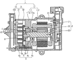
- FIG. 1 is a sectional view illustrating a compressor in accordance with an embodiment of the present disclosure
- FIG. 2 is an enlarged view of portion A of FIG. 1 ;
- FIG. 3 is a front perspective view illustrating a reducer of FIG. 2 ;
- FIG. 4 is a rear perspective view of the reducer of FIG. 2 ;
- FIG. 5 is a sectional view illustrating a reducer of a compressor in accordance with another embodiment of the present disclosure
- FIG. 6 is a sectional view illustrating a reducer of a compressor in accordance with yet another embodiment of the present disclosure.
- FIG. 7 is an exploded perspective view illustrating the reducer of FIG. 6 .
- FIG. 1 is a sectional view illustrating a compressor in accordance with an embodiment of the present disclosure.
- FIG. 2 is an enlarged view of portion A of FIG. 1 .
- FIG. 3 is a front perspective view illustrating a reducer of FIG. 2 .
- FIG. 4 is a rear perspective view of the reducer of FIG. 2 .
- the compressor in accordance with the embodiment of the present disclosure includes a casing 1 , a drive unit 2 , a compression unit 2 , an oil recovery passage 4 , and a reducer 5 .
- the drive unit 2 may generate driving force.
- the compression unit 3 may receive driving force from the drive unit 2 , suck refrigerant from a suction space V 1 of the casing 1 , compress the sucked refrigerant, and discharge the compressed refrigerant to a discharge space V 2 of the casing 1 .
- the oil recovery passage 4 may recover oil separated from refrigerant in the discharge space V 2 to the suction space V 1 .
- the reducer 5 is inserted into the oil recovery passage 4 and configured to reduce the pressure of oil passing through the oil recovery passage 4 .
- the casing 1 may include a first housing 11 having the suction space V 1 , and a second housing 12 which is coupled to the first housing 11 and has the discharge space V 2 .
- the first housing 11 may include a center housing 111 in which a main frame 111 b is formed, and a front housing 112 which is coupled to the center housing 111 and forms the suction space V 1 .
- the center housing 111 may include an outer center-housing sidewall 111 a having an annular shape, and the main frame 111 b covering one end of the outer center-housing sidewall 111 a.
- the other end of the outer center-housing sidewall 111 a may be covered with the front housing 112 .
- the suction space V 1 may be formed by the outer center-housing sidewall 111 a , the main frame 111 b , and the front housing 112 .
- the outer center-housing sidewall 111 a may communicate with a refrigerant intake pipe (not show) configured to guide refrigerant from the outside of the compressor into the suction space V 1 .
- the main frame 111 b may have a suction hole (not shown) formed to guide refrigerant from the suction space V 1 to the compression unit 3 .
- the main frame 111 b may have a back pressure chamber B formed to pressurize a turning scroll 32 , which will be described later, to a fixed scroll 31 , which will be also described later.
- the second housing 12 may include the fixed scroll 31 and a rear housing 122 .
- the fixed scroll 31 may be disposed on a side opposite to the front housing 112 based on the center housing 111 , and may be coupled to the center housing 111 .
- the rear housing 122 may be disposed on a side opposite to the center housing 111 based on the fixed scroll 31 , and may be coupled to the fixed scroll 31 to form the discharge space V 2 .
- the fixed scroll 31 forms not only the compression unit 3 but also the second housing 12 .
- the present disclosure is not limited to this.
- the rear housing 122 may be coupled to the center housing 111 to form the second housing 12
- the fixed scroll 31 may be housed in the second housing 12 to form the compression unit 3 .
- the second housing 12 (in more detail, the rear housing 122 ) may communicate with a refrigerant discharge pipe (not shown) configured to guide refrigerant from the discharge space V 2 to the outside of the compressor.
- the discharge space V 2 of the second housing 12 may communicate with the oil recovery passage 4 .
- the drive unit 2 may be formed of a stator 21 , a rotor 22 disposed inside the stator 21 and configured to rotate by interaction with the stator 21 , and a motor having a rotating shaft 23 coupled to the rotor 22 .
- the stator 21 and the rotor 22 may be housed in the suction space V 1 .
- the rotating shaft 23 may pass through the main frame 111 b and extend from the suction space V 1 toward the discharge space V 2 .
- the compression unit 3 may include the fixed scroll 31 , and the turning scroll 32 which forms a pair of compression chambers C along with the fixed scroll 31 .
- the turning scroll 32 may be interposed between the main frame 111 b and the fixed scroll 31 , and supported by the main frame 111 b .
- the turning scroll 32 may be configured to be rotatable using rotating force transmitted from the drive unit 2 through the rotating shaft 23 .
- the oil recovery passage 4 may be formed by communicating a plurality of separated passage holes with each other.
- the oil recovery passage 4 may include a first passage hole 4 a which is formed in the fixed scroll 31 and communicates with the discharge space V 2 , and a second passage hole 4 b which is formed in the center housing 111 and communicates the first passage hole 4 a with the suction space V 1 .
- the oil recovery passage 4 may further include a third passage hole 4 c which communicates an inlet end of the second passage hole 4 b with the back pressure chamber B.
- the reducer 5 may include a first reducing member 5 a and a second reducing member 5 b .
- the first reducing member 5 a may be disposed in the first passage hole 4 a so as to reduce the pressure of oil drawn from the discharge space V 2 from a discharge pressure into an intermediate pressure.
- the second reducing member 5 b may be disposed in the second passage hole 4 b so as to reduce the pressure of oil drawn from the first passage hole 4 a from the intermediate pressure into a suction pressure.
- the reducer 5 may be formed of a so-called nozzle-type orifice in which a pressure to be reduced is changed depending on a difference in pressure between an upstream side and a downstream side of the reducer.
- the reducer 5 may include a shaft part 52 which extends from an upstream side of the oil recovery passage 4 to a downstream side thereof, and a treaded part 54 which is formed on an outer circumferential surface of a medial portion of the shaft part 52 .
- the shaft part 52 may have the form of a cylinder, an outer diameter of which is less than an inner diameter D 4 of the oil recovery passage 4 .
- the spiral part 54 may be formed of a tread protruding from the outer circumferential surface of the shaft part 52 .
- the spiral part 54 may be formed such that the outer diameter D 54 of the spiral part 54 (that is two times a distance between a center axis of the shaft part 52 and a spiral line of the spiral part 54 ) is greater than or equal to the inner diameter D 4 of the oil recovery passage 4 so that the reducer 5 can be forcibly fitted into the oil recovery passage 4 .
- the spiral part 54 is formed such that the outer diameter D 54 of the spiral part 54 is greater than or equal to the inner diameter D 4 of the oil recovery passage 4 before the reducer 5 is inserted into the oil recovery passage 54 .
- the outer diameter D 54 of the spiral part 54 is changed to a value equal to the inner diameter D 4 of the oil recovery passage 4 so that the reducer 5 can be forcibly fitted to the inner circumferential surface of the oil recovery passage 4 .
- the shaft part 52 and the spiral part 54 that have the above-mentioned configurations may form, along with the oil recovery passage 4 , an oil transfer groove G which increases the distance that oil moves in the oil recovery passage 4 to reduce the pressure of oil.
- the outer circumferential surface of the shaft part 52 , the side surface of the spiral part 54 , and the inner circumferential surface of the oil recovery passage 4 may form the oil transfer groove G.
- the oil transfer groove G spirally moves oil the distance that the oil moves may be increased.
- the spiral part 54 may be damaged.
- a trailing end of the spiral part 54 that is clamped to perform the operation of inserting the reducer 5 into the oil recovery passage 4 may be crushed by force applied to the trailing end of the spiral part 54 .
- the reducer 5 in accordance with the present embodiment may further include a rib part 56 provided to prevent the spiral part 54 from being damaged when the reducer 5 is inserted into the oil recovery passage 4 .
- the rib part 56 may include a first rib part 56 a formed on an outer circumferential surface of a first end of the shaft part 52 , and a second rib part 56 b formed on an outer circumferential surface of the shaft part 52 .
- the first end of the shaft part 52 is a portion of the reducer 5 that is first inserted into the oil recovery passage 4 during the process of inserting the reducer 5 into the oil recovery passage 4
- the second end of the shaft part 52 is a portion of the reducer 5 that is lastly inserted into the oil recovery passage 4 during the process of inserting the reducer 5 into the oil recovery passage 4 .
- the first rib part 56 a may comprise a plurality of first rib parts 56 a for guiding the position of the reducer 5 such that the axial direction of the shaft part 52 is parallel to the axial direction of the oil recovery passage 4 when the reducer 5 is inserted into the oil recovery passage 4 .
- the plurality of first rib parts 56 a may be disposed at regular intervals along a circumferential direction of the shaft part 52 .
- Each first rib part 56 a may extend along the axial direction of the shaft part 52 .
- the plurality of first rib parts 56 a are formed such that the distances between the center axis of the shaft part 52 and the respective outer circumferential surfaces of the first rib parts 56 a are equivalent to each other so that the plurality of first rib parts 56 a are forcibly fitted into the oil recovery passage 4 so as to more reliably guide the position of the reducer 5 .
- an outer diameter D 56 a of the plurality of first rib parts 56 a (that is two times the distance between the center axis of the shaft part 52 and the outer circumferential surface of each first rib part 56 a ) may be greater than or equal to the inner diameter D 4 of the oil recovery passage 4 .
- the plurality of first rib parts 56 a are formed such that the outer diameter D 56 a of the first rib parts 56 a is greater than or equal to the inner diameter D 4 of the oil recovery passage 4 before the reducer 5 is inserted into the oil recovery passage 1 .
- the outer diameter D 56 a of the first rib parts 56 a is changed to a value equal to the inner diameter D 4 of the oil recovery passage 4 so that the reducer 5 can be forcibly fitted to the inner circumferential surface of the oil recovery passage 4 .
- the plurality of first rib parts 56 a are disposed at the upstream side of the spiral part 54 and block an inlet side of the oil transfer groove G to reduce the flow cross-section area of the inlet side of the oil transfer groove G.
- one of the plurality of first rib parts 56 a may be formed to overlap the leading end of the spiral part 54 in the axial direction of the shaft part 52 .
- each first rib part 56 a expands in the circumferential direction and thus reduce the flow cross-sectional area of the inlet side of the oil transfer groove G.
- the outer diameter 56 a of the plurality of first rib parts 56 a may be less than or equal to the outer diameter D 54 of the spiral part 54 .
- the second rib part 56 b may have the same shape as that of the first rib part 56 a , taking into account the case where the reducer 5 is inserted into the oil recovery passage 4 in the reverse direction, e.g., due to a mistake of a worker.
- the second rib part 56 b may comprise a plurality of second rib parts 56 b .
- the plurality of second rib parts 56 b may be disposed at regular intervals along the circumferential direction of the shaft part 52 .
- Each second rib part 56 b may extend along the axial direction of the shaft part 52 .
- the plurality of second rib parts 56 b are formed such that the distances between the center axis of the shaft part 52 and the respective outer circumferential surfaces of the second rib parts 56 b are equivalent to each other.
- an outer diameter D 56 b of the plurality of second rib parts 56 b (that is two times the distance between the center axis of the shaft part 52 and the outer circumferential surface of each second rib part 56 b ) may be greater than or equal to the inner diameter D 4 of the oil recovery passage 4 .
- the plurality of second rib parts 56 b are formed such that the outer diameter D 56 b of the second rib parts 56 b is greater than or equal to the inner diameter D 4 of the oil recovery passage 4 before the reducer 5 is inserted into the oil recovery passage 2 .
- the outer diameter D 56 b of the second rib parts 56 b is changed to a value equal to the inner diameter D 4 of the oil recovery passage 4 so that the reducer 5 can be forcibly fitted to the inner circumferential surface of the oil recovery passage 4 .
- one of the plurality of second rib parts 56 b may be formed to overlap the trailing end of the spiral part 54 in the axial direction of the shaft part 52 .
- outer diameter D 56 b of the plurality of second rib parts 56 b may be less than or equal to the outer diameter D 54 of the spiral part 54 .
- the rotating shaft 23 along with the rotor 22 may rotate to transmit rotating force to the turning scroll 32 .
- the turning scroll 32 is rotated by the rotating shaft 23 , whereby the volume of the compression chamber C is reduced toward the central portion of the compressor.
- refrigerant may be sucked into the compression chamber C through the refrigerant suction pipe (not shown), the suction space V 1 , and the suction hole (not shown).
- the refrigerant that has been sucked into the compression chamber C may be transferred toward the central portion along a transfer path of the compression chamber C and thus compressed, before being discharged to the discharge space V 2 .
- the refrigerant that has been discharged to the discharge space V 2 may be discharged out of the compressor through the refrigerant discharge pipe (not shown) after oil that has been contained in the refrigerant is separated from the refrigerant by the oil separator.
- the oil that has been separated from the refrigerant by the oil separator may be collected in a lower portion of the discharge space V 2 , and recovered to the suction space V 1 through the oil recovery passage 4 .
- the oil recovered to the suction space V 1 may be supplied, along with refrigerant to be compressed, to the corresponding drive parts.
- the oil collected in the discharge space V 2 may be drawn into the first passage hole 4 a.
- the oil that has been drawn into the first passage hole 4 a may be reduced in pressure from the discharge pressure to an intermediate pressure lower than the discharge pressure while passing through the first reducing member 5 a.
- the oil that has passed through the first reducing member 5 a may diverge so that some of the oil may be drawn into the second passage hole 4 b and the other oil may be drawn into the third passage hole 4 c.
- the oil that has been drawn into the second passage hole 4 b may be reduced in pressure from the intermediate pressure to the suction pressure lower than the intermediate pressure while passing through the second reducing member 5 b.
- the oil that has passed through the second reducing member 5 b may be recovered into the suction space V 1 .
- the oil that has been drawn into the third passage hole 4 c may be supplied into the back pressure chamber B.
- the oil that has been drawn into the back pressure chamber B may pressurize the turning scroll 32 toward the fixed scroll 31 , lubricate a bearing that supports the rotating shaft 23 , a junction between the main frame 111 b and the turning scroll 32 , and so forth, and then be drawn into the compression chamber C or the suction space V 1 .
- the spiral part 54 may be prevented from being damaged when the reducer 5 is inserted into the oil recovery passage 4 .
- the reducer 5 may be inserted into the oil recovery passage 4 in a state in which the axis of the shaft part 52 is parallel to the axial direction of the oil recovery passage 4 . Thereby, the leading end of the spiral part 54 may be prevented from being crushed and damaged by the oil recovery passage 4 .
- the reducer 5 includes the second rib parts 56 b , the second rib parts 56 b in lieu of the trailing end of the spiral part 54 may be clamped.
- the second rib parts 56 b may substitute for the part to be clamped to perform the operation of inserting the reducer 5 into the oil recovery passage 4 .
- the trailing end of the spiral part 54 may be prevented from being crushed and damaged by force applied to the trailing end of the spiral part 54 when the trailing end of the spiral part 54 is clamped.
- the configuration using the rib part 56 capable of preventing damage to the spiral part 54 may not only solve the problem that oil may not be reduced in pressure or the oil recovery passage 4 may be clogged, but may also reduce the costs required to prevent the reducer 5 from being damaged, check the conditions of the reducer 5 , and repair reducer 5 .
- the rib part 56 may prevent the spiral part 54 from being damaged. Hence, the costs needed to manage the dimensions of the oil recovery passage 4 may be reduced.
- the production cost of a part in which the oil recovery passage 4 is formed may be reduced.
- the plating layer is formed on the surface of the fixed scroll 31 so as to enhance abrasion resistance and lubrication, taking into account friction between the fixed scroll 31 and the turning scroll 32 .
- the fixed scroll 31 is manufactured through the complex manufacturing process (including the fixed scroll processing operation, the oil recovery passage masking operation, the plating operation, the operation of removing the mask from the oil recovery passage, and the reducer force-fitting operation) for preventing the plating layer from being formed on the first passage hole 4 a .
- the dimensions of the oil recovery passage 4 may be loosely managed. Thereby, even when the plating layer is formed on the first passage hole 4 a , the spiral part 54 may be prevented from being damaged.
- the fixed scroll 31 may be manufactured through a comparatively simple manufacturing process (including a fixed scroll processing operation, a plating operation, and a reducer force-fitting operation) from which the masking operation and the operation of removing the mask from the oil recovery passage 4 are omitted.
- the reducer 5 may be inserted into the first passage hole 4 a on which the plating layer has been formed. As such, as the manufacturing process is simplified, the production cost of the fixed scroll 31 may be reduced.
- the rib part 56 includes the first rib part 56 a and the second rib part 56 b .
- the rib part 56 may include only any one of the first rib part 56 a and the second rib part 56 b .
- the costs required to form the reducer 5 may be reduced, and the leading end or the trailing end of the spiral part 54 may be prevented from being damaged.
- the rib part 56 includes the first rib part 56 a
- the costs needed to form the second rib part 56 b is not required, and the leading end of the spiral part 54 may be prevented from being damaged.
- the rib part 56 includes the second rib part 56 b
- the costs needed to form the first rib part 56 a is not required, and the trailing end of the spiral part 54 may be prevented from being damaged.
- the rib part 56 include both the first rib part 56 a and the second rib part 56 b.
- the shaft part 52 , the spiral part 54 , and the rib part 56 are integrally formed with each other.
- the shaft part 52 and the spiral part 54 are integrally formed with each other, and the rib part 56 may be removably provided on the shaft part 52 and the spiral part 54 .
- the rib part 56 may be coupled to the shaft part 52 and the spiral part 54 before being inserted into the oil recovery passage 4 .
- the rib part 56 may be inserted into the oil recovery passage 4 before being coupled to the shaft part 52 and the spiral part 54 .
- the reducer 5 may include at least one of the first rib part 56 a and the second rib part 56 b , as needed.
- the shaft part 52 , the spiral part 54 , and the rib part 56 are defective, only the defective parts may be replaced with new ones. Therefore, replacement costs may be reduced.
Abstract
Description
Claims (10)
Applications Claiming Priority (2)
| Application Number | Priority Date | Filing Date | Title |
|---|---|---|---|
| KR10-2018-0032421 | 2018-03-21 | ||
| KR1020180032421A KR102418813B1 (en) | 2018-03-21 | 2018-03-21 | Compressor |
Publications (2)
| Publication Number | Publication Date |
|---|---|
| US20190293072A1 US20190293072A1 (en) | 2019-09-26 |
| US11073152B2 true US11073152B2 (en) | 2021-07-27 |
Family
ID=67848053
Family Applications (1)
| Application Number | Title | Priority Date | Filing Date |
|---|---|---|---|
| US16/356,093 Active 2039-11-08 US11073152B2 (en) | 2018-03-21 | 2019-03-18 | Compressor capable of preventing a reducer from being damaged |
Country Status (5)
| Country | Link |
|---|---|
| US (1) | US11073152B2 (en) |
| JP (1) | JP6952733B2 (en) |
| KR (1) | KR102418813B1 (en) |
| CN (1) | CN110296078B (en) |
| DE (1) | DE102019106966A1 (en) |
Citations (9)
| Publication number | Priority date | Publication date | Assignee | Title |
|---|---|---|---|---|
| JP2001353431A (en) | 2000-06-12 | 2001-12-25 | Noritake Co Ltd | Static mixer element, device and method using the same and heat exchanging device and method |
| US20050129536A1 (en) * | 2003-12-10 | 2005-06-16 | Shinichi Ohtake | Compressor |
| US20090142202A1 (en) * | 2007-11-29 | 2009-06-04 | Yoshinori Inoue | Structure for mounting a filter in a compressor |
| US20130028730A1 (en) * | 2010-03-31 | 2013-01-31 | Mitsubishi Heavy Industries, Ltd. | Compressor |
| JP2014009831A (en) | 2012-06-28 | 2014-01-20 | Calsonic Kansei Corp | Double pipe and manufacturing method thereof |
| KR20150099901A (en) | 2014-02-24 | 2015-09-02 | 한온시스템 주식회사 | A device for transporting oil in a compressor |
| US20160136555A1 (en) * | 2013-08-28 | 2016-05-19 | Mitsubishi Heavy Industries Automotive Thermal Systems Co., Ltd. | Oil separator, and compressor provided with same |
| JP2017527738A (en) | 2015-05-26 | 2017-09-21 | ハンオン システムズ | Compressor having oil recovery means |
| WO2017164539A1 (en) | 2016-03-23 | 2017-09-28 | 한온시스템 주식회사 | Compressor |
Family Cites Families (10)
| Publication number | Priority date | Publication date | Assignee | Title |
|---|---|---|---|---|
| JP2002168183A (en) * | 2000-12-04 | 2002-06-14 | Matsushita Electric Ind Co Ltd | Scroll compressor |
| JP4470636B2 (en) * | 2004-08-04 | 2010-06-02 | ダイキン工業株式会社 | Scroll type fluid machine |
| JP4698417B2 (en) * | 2005-12-28 | 2011-06-08 | 株式会社デンソー | Manufacturing method of double pipe |
| JP4894357B2 (en) * | 2006-06-02 | 2012-03-14 | 株式会社豊田自動織機 | Compressor |
| JP2009209820A (en) * | 2008-03-05 | 2009-09-17 | Daikin Ind Ltd | Scroll compressor |
| CN201339582Y (en) * | 2008-12-30 | 2009-11-04 | 上海三电贝洱汽车空调有限公司 | Oil separation filter of air conditioning compressor |
| CN201615058U (en) * | 2009-11-26 | 2010-10-27 | 朱文龙 | Vacuum pump with lubricant beforehand spiral flow centrifugal filter |
| CN104251196B (en) * | 2013-06-28 | 2016-10-05 | Lg电子株式会社 | Linearkompressor |
| JP2018035911A (en) * | 2016-09-02 | 2018-03-08 | カルソニックカンセイ株式会社 | Double tube |
| KR101876513B1 (en) | 2016-09-22 | 2018-07-09 | 청호나이스 주식회사 | Capsule Assembly Containing Raw Material for Beverage |
-
2018
- 2018-03-21 KR KR1020180032421A patent/KR102418813B1/en active IP Right Grant
-
2019
- 2019-03-06 JP JP2019040630A patent/JP6952733B2/en active Active
- 2019-03-07 CN CN201910171851.5A patent/CN110296078B/en active Active
- 2019-03-18 US US16/356,093 patent/US11073152B2/en active Active
- 2019-03-19 DE DE102019106966.1A patent/DE102019106966A1/en active Pending
Patent Citations (10)
| Publication number | Priority date | Publication date | Assignee | Title |
|---|---|---|---|---|
| JP2001353431A (en) | 2000-06-12 | 2001-12-25 | Noritake Co Ltd | Static mixer element, device and method using the same and heat exchanging device and method |
| US20050129536A1 (en) * | 2003-12-10 | 2005-06-16 | Shinichi Ohtake | Compressor |
| US20090142202A1 (en) * | 2007-11-29 | 2009-06-04 | Yoshinori Inoue | Structure for mounting a filter in a compressor |
| US20130028730A1 (en) * | 2010-03-31 | 2013-01-31 | Mitsubishi Heavy Industries, Ltd. | Compressor |
| JP2014009831A (en) | 2012-06-28 | 2014-01-20 | Calsonic Kansei Corp | Double pipe and manufacturing method thereof |
| US20160136555A1 (en) * | 2013-08-28 | 2016-05-19 | Mitsubishi Heavy Industries Automotive Thermal Systems Co., Ltd. | Oil separator, and compressor provided with same |
| KR20150099901A (en) | 2014-02-24 | 2015-09-02 | 한온시스템 주식회사 | A device for transporting oil in a compressor |
| JP2017527738A (en) | 2015-05-26 | 2017-09-21 | ハンオン システムズ | Compressor having oil recovery means |
| WO2017164539A1 (en) | 2016-03-23 | 2017-09-28 | 한온시스템 주식회사 | Compressor |
| US20180195505A1 (en) * | 2016-03-23 | 2018-07-12 | Hanon Systems | Compressor |
Also Published As
| Publication number | Publication date |
|---|---|
| US20190293072A1 (en) | 2019-09-26 |
| CN110296078A (en) | 2019-10-01 |
| DE102019106966A1 (en) | 2019-09-26 |
| JP6952733B2 (en) | 2021-10-20 |
| KR102418813B1 (en) | 2022-07-11 |
| KR20190110681A (en) | 2019-10-01 |
| JP2019167953A (en) | 2019-10-03 |
| CN110296078B (en) | 2021-05-07 |
Similar Documents
| Publication | Publication Date | Title |
|---|---|---|
| US10527041B2 (en) | Compressor having oil recovery means | |
| US8202071B2 (en) | Motor-driven scroll type compressor | |
| CN101988504B (en) | Rotary compressor | |
| JP5527349B2 (en) | Vane type compressor | |
| US11073152B2 (en) | Compressor capable of preventing a reducer from being damaged | |
| KR102452563B1 (en) | Compressor | |
| KR20090093816A (en) | Gas compressor | |
| US11286936B2 (en) | Scroll compressor | |
| CN107061275B (en) | Slip sheet of rotary compressor, rotary compressor with slip sheet and vehicle | |
| KR102138564B1 (en) | Compressor | |
| JP3616056B2 (en) | Rotary compressor | |
| KR102087135B1 (en) | Scroll compressor with oil recovery means | |
| KR102649532B1 (en) | Scroll compressor | |
| KR102500647B1 (en) | Compressor | |
| KR101742101B1 (en) | Swash plate type compressor | |
| KR100963987B1 (en) | Swash pate type compressor | |
| KR20010076889A (en) | Low pressure type rotary compressor | |
| KR20170071048A (en) | Swash plate compressor with oil separator | |
| JP2009235910A (en) | Gas compressor | |
| KR102141873B1 (en) | A device for separating oil in a compressor | |
| KR20150082767A (en) | Compressor having check valve | |
| JP2007085298A (en) | Compressor | |
| KR20120063284A (en) | Compressor | |
| KR100311466B1 (en) | low pressure type rotary compressor | |
| KR20120027793A (en) | Compressor |
Legal Events
| Date | Code | Title | Description |
|---|---|---|---|
| FEPP | Fee payment procedure |
Free format text: ENTITY STATUS SET TO UNDISCOUNTED (ORIGINAL EVENT CODE: BIG.); ENTITY STATUS OF PATENT OWNER: LARGE ENTITY |
|
| AS | Assignment |
Owner name: HANON SYSTEMS, KOREA, REPUBLIC OF Free format text: ASSIGNMENT OF ASSIGNORS INTEREST;ASSIGNORS:KIM, HONG MIN;JEONG, SOO CHEOL;LIM, KWEON SOO;AND OTHERS;REEL/FRAME:048937/0896 Effective date: 20190325 |
|
| STPP | Information on status: patent application and granting procedure in general |
Free format text: NON FINAL ACTION MAILED |
|
| STPP | Information on status: patent application and granting procedure in general |
Free format text: RESPONSE TO NON-FINAL OFFICE ACTION ENTERED AND FORWARDED TO EXAMINER |
|
| STPP | Information on status: patent application and granting procedure in general |
Free format text: NOTICE OF ALLOWANCE MAILED -- APPLICATION RECEIVED IN OFFICE OF PUBLICATIONS |
|
| STPP | Information on status: patent application and granting procedure in general |
Free format text: AWAITING TC RESP., ISSUE FEE NOT PAID |
|
| STPP | Information on status: patent application and granting procedure in general |
Free format text: NOTICE OF ALLOWANCE MAILED -- APPLICATION RECEIVED IN OFFICE OF PUBLICATIONS |
|
| STPP | Information on status: patent application and granting procedure in general |
Free format text: PUBLICATIONS -- ISSUE FEE PAYMENT RECEIVED |
|
| STPP | Information on status: patent application and granting procedure in general |
Free format text: PUBLICATIONS -- ISSUE FEE PAYMENT VERIFIED |
|
| STCF | Information on status: patent grant |
Free format text: PATENTED CASE |