US11071675B2 - Lower limb exoskeleton system having jump-down cushioning function and method of using the same - Google Patents
Lower limb exoskeleton system having jump-down cushioning function and method of using the same Download PDFInfo
- Publication number
- US11071675B2 US11071675B2 US16/605,698 US201916605698A US11071675B2 US 11071675 B2 US11071675 B2 US 11071675B2 US 201916605698 A US201916605698 A US 201916605698A US 11071675 B2 US11071675 B2 US 11071675B2
- Authority
- US
- United States
- Prior art keywords
- bars
- thigh
- frames
- bottom ends
- joint movement
- Prior art date
- Legal status (The legal status is an assumption and is not a legal conclusion. Google has not performed a legal analysis and makes no representation as to the accuracy of the status listed.)
- Active, expires
Links
Images


Classifications
-
- B—PERFORMING OPERATIONS; TRANSPORTING
- B25—HAND TOOLS; PORTABLE POWER-DRIVEN TOOLS; MANIPULATORS
- B25J—MANIPULATORS; CHAMBERS PROVIDED WITH MANIPULATION DEVICES
- B25J9/00—Program-controlled manipulators
- B25J9/0006—Exoskeletons, i.e. resembling a human figure
-
- A—HUMAN NECESSITIES
- A61—MEDICAL OR VETERINARY SCIENCE; HYGIENE
- A61H—PHYSICAL THERAPY APPARATUS, e.g. DEVICES FOR LOCATING OR STIMULATING REFLEX POINTS IN THE BODY; ARTIFICIAL RESPIRATION; MASSAGE; BATHING DEVICES FOR SPECIAL THERAPEUTIC OR HYGIENIC PURPOSES OR SPECIFIC PARTS OF THE BODY
- A61H1/00—Apparatus for passive exercising; Vibrating apparatus; Chiropractic devices, e.g. body impacting devices, external devices for briefly extending or aligning unbroken bones
- A61H1/02—Stretching or bending or torsioning apparatus for exercising
- A61H1/0237—Stretching or bending or torsioning apparatus for exercising for the lower limbs
- A61H1/024—Knee
-
- A—HUMAN NECESSITIES
- A61—MEDICAL OR VETERINARY SCIENCE; HYGIENE
- A61H—PHYSICAL THERAPY APPARATUS, e.g. DEVICES FOR LOCATING OR STIMULATING REFLEX POINTS IN THE BODY; ARTIFICIAL RESPIRATION; MASSAGE; BATHING DEVICES FOR SPECIAL THERAPEUTIC OR HYGIENIC PURPOSES OR SPECIFIC PARTS OF THE BODY
- A61H1/00—Apparatus for passive exercising; Vibrating apparatus; Chiropractic devices, e.g. body impacting devices, external devices for briefly extending or aligning unbroken bones
- A61H1/02—Stretching or bending or torsioning apparatus for exercising
- A61H1/0237—Stretching or bending or torsioning apparatus for exercising for the lower limbs
- A61H1/0244—Hip
-
- A—HUMAN NECESSITIES
- A61—MEDICAL OR VETERINARY SCIENCE; HYGIENE
- A61H—PHYSICAL THERAPY APPARATUS, e.g. DEVICES FOR LOCATING OR STIMULATING REFLEX POINTS IN THE BODY; ARTIFICIAL RESPIRATION; MASSAGE; BATHING DEVICES FOR SPECIAL THERAPEUTIC OR HYGIENIC PURPOSES OR SPECIFIC PARTS OF THE BODY
- A61H3/00—Appliances for aiding patients or disabled persons to walk about
- A61H2003/007—Appliances for aiding patients or disabled persons to walk about secured to the patient, e.g. with belts
-
- A—HUMAN NECESSITIES
- A61—MEDICAL OR VETERINARY SCIENCE; HYGIENE
- A61H—PHYSICAL THERAPY APPARATUS, e.g. DEVICES FOR LOCATING OR STIMULATING REFLEX POINTS IN THE BODY; ARTIFICIAL RESPIRATION; MASSAGE; BATHING DEVICES FOR SPECIAL THERAPEUTIC OR HYGIENIC PURPOSES OR SPECIFIC PARTS OF THE BODY
- A61H2201/00—Characteristics of apparatus not provided for in the preceding codes
- A61H2201/01—Constructive details
- A61H2201/0165—Damping, vibration related features
-
- A—HUMAN NECESSITIES
- A61—MEDICAL OR VETERINARY SCIENCE; HYGIENE
- A61H—PHYSICAL THERAPY APPARATUS, e.g. DEVICES FOR LOCATING OR STIMULATING REFLEX POINTS IN THE BODY; ARTIFICIAL RESPIRATION; MASSAGE; BATHING DEVICES FOR SPECIAL THERAPEUTIC OR HYGIENIC PURPOSES OR SPECIFIC PARTS OF THE BODY
- A61H2201/00—Characteristics of apparatus not provided for in the preceding codes
- A61H2201/01—Constructive details
- A61H2201/0173—Means for preventing injuries
-
- A—HUMAN NECESSITIES
- A61—MEDICAL OR VETERINARY SCIENCE; HYGIENE
- A61H—PHYSICAL THERAPY APPARATUS, e.g. DEVICES FOR LOCATING OR STIMULATING REFLEX POINTS IN THE BODY; ARTIFICIAL RESPIRATION; MASSAGE; BATHING DEVICES FOR SPECIAL THERAPEUTIC OR HYGIENIC PURPOSES OR SPECIFIC PARTS OF THE BODY
- A61H2201/00—Characteristics of apparatus not provided for in the preceding codes
- A61H2201/01—Constructive details
- A61H2201/0192—Specific means for adjusting dimensions
-
- A—HUMAN NECESSITIES
- A61—MEDICAL OR VETERINARY SCIENCE; HYGIENE
- A61H—PHYSICAL THERAPY APPARATUS, e.g. DEVICES FOR LOCATING OR STIMULATING REFLEX POINTS IN THE BODY; ARTIFICIAL RESPIRATION; MASSAGE; BATHING DEVICES FOR SPECIAL THERAPEUTIC OR HYGIENIC PURPOSES OR SPECIFIC PARTS OF THE BODY
- A61H2201/00—Characteristics of apparatus not provided for in the preceding codes
- A61H2201/12—Driving means
- A61H2201/1207—Driving means with electric or magnetic drive
- A61H2201/1215—Rotary drive
-
- A—HUMAN NECESSITIES
- A61—MEDICAL OR VETERINARY SCIENCE; HYGIENE
- A61H—PHYSICAL THERAPY APPARATUS, e.g. DEVICES FOR LOCATING OR STIMULATING REFLEX POINTS IN THE BODY; ARTIFICIAL RESPIRATION; MASSAGE; BATHING DEVICES FOR SPECIAL THERAPEUTIC OR HYGIENIC PURPOSES OR SPECIFIC PARTS OF THE BODY
- A61H2201/00—Characteristics of apparatus not provided for in the preceding codes
- A61H2201/16—Physical interface with patient
- A61H2201/1602—Physical interface with patient kind of interface, e.g. head rest, knee support or lumbar support
- A61H2201/1628—Pelvis
- A61H2201/163—Pelvis holding means therefor
-
- A—HUMAN NECESSITIES
- A61—MEDICAL OR VETERINARY SCIENCE; HYGIENE
- A61H—PHYSICAL THERAPY APPARATUS, e.g. DEVICES FOR LOCATING OR STIMULATING REFLEX POINTS IN THE BODY; ARTIFICIAL RESPIRATION; MASSAGE; BATHING DEVICES FOR SPECIAL THERAPEUTIC OR HYGIENIC PURPOSES OR SPECIFIC PARTS OF THE BODY
- A61H2201/00—Characteristics of apparatus not provided for in the preceding codes
- A61H2201/16—Physical interface with patient
- A61H2201/1602—Physical interface with patient kind of interface, e.g. head rest, knee support or lumbar support
- A61H2201/164—Feet or leg, e.g. pedal
- A61H2201/1642—Holding means therefor
-
- A—HUMAN NECESSITIES
- A61—MEDICAL OR VETERINARY SCIENCE; HYGIENE
- A61H—PHYSICAL THERAPY APPARATUS, e.g. DEVICES FOR LOCATING OR STIMULATING REFLEX POINTS IN THE BODY; ARTIFICIAL RESPIRATION; MASSAGE; BATHING DEVICES FOR SPECIAL THERAPEUTIC OR HYGIENIC PURPOSES OR SPECIFIC PARTS OF THE BODY
- A61H2201/00—Characteristics of apparatus not provided for in the preceding codes
- A61H2201/16—Physical interface with patient
- A61H2201/1602—Physical interface with patient kind of interface, e.g. head rest, knee support or lumbar support
- A61H2201/165—Wearable interfaces
-
- A—HUMAN NECESSITIES
- A61—MEDICAL OR VETERINARY SCIENCE; HYGIENE
- A61H—PHYSICAL THERAPY APPARATUS, e.g. DEVICES FOR LOCATING OR STIMULATING REFLEX POINTS IN THE BODY; ARTIFICIAL RESPIRATION; MASSAGE; BATHING DEVICES FOR SPECIAL THERAPEUTIC OR HYGIENIC PURPOSES OR SPECIFIC PARTS OF THE BODY
- A61H2201/00—Characteristics of apparatus not provided for in the preceding codes
- A61H2201/50—Control means thereof
- A61H2201/5007—Control means thereof computer controlled
-
- A—HUMAN NECESSITIES
- A61—MEDICAL OR VETERINARY SCIENCE; HYGIENE
- A61H—PHYSICAL THERAPY APPARATUS, e.g. DEVICES FOR LOCATING OR STIMULATING REFLEX POINTS IN THE BODY; ARTIFICIAL RESPIRATION; MASSAGE; BATHING DEVICES FOR SPECIAL THERAPEUTIC OR HYGIENIC PURPOSES OR SPECIFIC PARTS OF THE BODY
- A61H2201/00—Characteristics of apparatus not provided for in the preceding codes
- A61H2201/50—Control means thereof
- A61H2201/5058—Sensors or detectors
- A61H2201/5069—Angle sensors
-
- A—HUMAN NECESSITIES
- A61—MEDICAL OR VETERINARY SCIENCE; HYGIENE
- A61H—PHYSICAL THERAPY APPARATUS, e.g. DEVICES FOR LOCATING OR STIMULATING REFLEX POINTS IN THE BODY; ARTIFICIAL RESPIRATION; MASSAGE; BATHING DEVICES FOR SPECIAL THERAPEUTIC OR HYGIENIC PURPOSES OR SPECIFIC PARTS OF THE BODY
- A61H2201/00—Characteristics of apparatus not provided for in the preceding codes
- A61H2201/50—Control means thereof
- A61H2201/5097—Control means thereof wireless
-
- A—HUMAN NECESSITIES
- A61—MEDICAL OR VETERINARY SCIENCE; HYGIENE
- A61H—PHYSICAL THERAPY APPARATUS, e.g. DEVICES FOR LOCATING OR STIMULATING REFLEX POINTS IN THE BODY; ARTIFICIAL RESPIRATION; MASSAGE; BATHING DEVICES FOR SPECIAL THERAPEUTIC OR HYGIENIC PURPOSES OR SPECIFIC PARTS OF THE BODY
- A61H2205/00—Devices for specific parts of the body
- A61H2205/10—Leg
Definitions
- the present invention belongs to the technical field of mechatronic engineering and biomedical engineering, and more particularly, to provide a lower limb exoskeleton system having jump-down cushioning function and a method of using the same.
- Lower limb exoskeleton is a wearable machine made of a metal frame, and can enhance the lower limb function of human bodies.
- the lower limb exoskeleton can drive mechanical joints to perform actions according to physical acts of human, and help a wearer to run faster and be high in loading capacity.
- the lower limb exoskeleton can assist in recovering the leg walking ability of the elderly and the disabled people wearing the lower limb exoskeleton, and even help paralyzed people to stand and walk again.
- the lower limb exoskeleton system provides the cushioning function for resisting ground reaction force based on an instruction given by the wearer when the wearer jumps down, so that the lower limb exoskeleton system can protect the lower limbs from being damaged when the wearer jumps down.
- the lower limb exoskeleton system has foot jump-down cushioning mechanisms at the points of the lower limb exoskeleton system with ground, which meet the cushioning requirements of 1.5 m jump-down height.
- a primary objective of the present invention is to provide a lower limb exoskeleton system having jump-down cushioning function and a method of using the same.
- the present invention provides a lower limb exoskeleton system having jump-down cushioning function.
- the lower limb exoskeleton system having jump-down cushioning function comprises a back frame, two hip joint movement mechanisms, two telescopic thigh bars, two knee joint movement mechanisms, two shank bars, two foot jump-down cushioning mechanisms, a waist binding frame, two upper leg binding frames and two lower leg binding frames.
- Two protruding ends of the back frame are connected with top ends of the hip joint movement mechanisms respectively, bottom ends of the hip joint movement mechanisms are connected with top ends of the telescopic thigh bars respectively, bottom ends of the telescopic thigh bars are connected with top ends of the knee joint movement mechanisms respectively, bottom ends of the knee joint movement mechanisms are connected with top ends of the shank bars respectively, and bottom ends of the shank bars are connected with the foot jump-down cushioning mechanisms respectively.
- the waist binding frame is arranged on an inner side of a horizontal part of the back frame, the upper leg binding frames are arranged on the telescopic thigh bars respectively, and the lower leg binding frames are arranged on the shank bars respectively.
- Each of the hip joint movement mechanisms consists of an abduction and adduction moving piece, a flexion and extension moving piece and an upper thigh bar connecting frame. Top ends of the abduction and adduction moving pieces are connected with the protruding ends of the back frame through bolts respectively, and bottom ends of the abduction and adduction moving pieces are connected with top ends of the flexion and extension moving pieces via two first pins respectively.
- Bottom ends of the flexion and extension moving pieces are connected with top ends of the upper thigh bar connecting frames via two second pins respectively.
- Each of the first pins and each of the second pins are perpendicular to each other.
- Each of the telescopic thigh bars consists of an upper thigh bar and a lower thigh bar, wherein three threaded through holes are formed on an upper end of each of the lower thigh bar in one row, and the upper ends of the lower thigh bars are connected with bottom ends of the upper thigh bars via the threaded through holes and bolts respectively.
- Top ends of the upper thigh bars are threadedly connected with upper thigh bar connecting frames of the hip joint movement mechanisms respectively, and the upper leg binding frames are connected to outer side surfaces of the upper thigh bars through bolts respectively.
- Two through holes are formed on an ear plate at a bottom end of each of the lower thigh bars in one row.
- Each of the knee joint movement mechanisms consists of a first lower thigh bar connecting frame, a second lower thigh bar connecting frame, a knee joint rotating piece, a harmonic reducer and a motor.
- the first lower thigh bar connecting frames are connected with bottom ends of lower thigh bars of the telescopic thigh bars through bolts respectively, the second lower thigh bar connecting frames are connected with bottom ends of lower thigh bars of the telescopic thigh bars through bolts respectively, and the first lower thigh bar connecting frames are connected with flexible gears of the harmonic reducers and the motors respectively.
- the harmonic reducers are located on inner sides of the first lower thigh bar connecting frames respectively, the motors are located on outer sides of the first lower thigh bar connecting frames respectively, harmonic generators of the harmonic reducers are connected with output shafts of the motors respectively, and steel output gears of the harmonic reducers are connected with the knee joint rotating pieces respectively.
- Fixed-angle notch bosses are arranged on connecting sides of the first and second lower thigh bar connecting frames, and the connecting sides of the first and second lower thigh bar connecting frames are connected with the knee joint rotating pieces.
- Each of the foot jump-down cushioning mechanisms consists of an electromagnet, an electromagnet fixing frame, two traction ropes, two clamps, a rubber mat, a shell, a moving sleeve, a cushioning spring, two reset springs and a control module.
- Top ends of the shells are connected with bottom ends of the shank bars through bolts respectively, the moving sleeves are arranged in inner sides of the shells respectively, the cushioning springs are arranged in the moving sleeves respectively, top ends of the cushioning springs are abutted to inner limiting plates in the shells respectively, the clamps are arranged on outer side surfaces of lower middle parts of the shells respectively, middle parts of the clamps are hinged with the shells respectively, two bosses are arranged on an outer side surface of an upper part of each of the shells, and the reset springs are arranged between side surfaces at top ends of the clamps and the bosses of the shell.
- top ends of the clamps are connected with bottom ends of the traction ropes respectively, and top ends of the traction ropes are connected with the electromagnets respectively.
- the electromagnets are arranged on the electromagnet fixing frames through bolts respectively, and the electromagnet fixing frames are fixed to the shank bars through bolts respectively.
- Bottom ends of the clamps are connected with bottom ends of the moving sleeves respectively, the bottom ends of the moving sleeves are connected with the rubber mats through bolts respectively, Bonding surfaces between the rubber mats and the moving sleeves are bound through rubber-metal adhesive glue, and grooves are formed on the rubber mats.
- the control modules are connected with the electromagnets respectively.
- Each of the control modules comprises an upper computer, a wireless communication module, a control panel and a relay, wherein the upper computers are connected with the control panels through the wireless communication modules respectively, the control panels are electrically connected with the relays respectively, and the relays are electrically connected with the electromagnets respectively.
- the present invention provides a method of using the lower limb exoskeleton system having jump-down cushioning function.
- the method of using the lower limb exoskeleton system having jump-down cushioning function comprises the following steps:
- fixing the lower limb exoskeleton system to a wearer comprises attaching the back frame of the lower limb exoskeleton system to a waist of the wearer through binding tapes and the waist binding frame, attaching the telescopic thigh bars to thighs of the wearer through the upper leg binding frames and binding tapes, and attaching the shank bars to shanks of the wearer through the lower leg binding frames and binding tapes;
- the upper computers sending instructions to the control panels via the wireless communication modules, output pins of the control panels controlling the relays to be connected, electrifying the electromagnets to be connected to drag the traction ropes and open the clamps, and the cushioning springs compressed into the shells pushing the moving sleeves to a limit position under an action of spring force;
- the upper computers sending instructions to control the control panels, and the output pins of the control panels controlling the relays to be disconnected so as to disconnect the electromagnets and loosen the traction ropes;
- the application proposes a lower limb exoskeleton system having jump-down cushioning function, i.e. the lower limb exoskeleton system provides the cushioning function for resisting ground reaction force based on an instruction given by the wearer while jumping down, so that the lower limb exoskeleton system can protect the lower limbs from being damaged when the wearer jumps down.
- the lower limb exoskeleton system has foot jump-down cushioning mechanisms at the points of contact with ground.
- the change in gravitational potential energy equals to the energy absorbed by the human body and the lower limb exoskeleton system through cushioning. Because energy absorbed by the human body through cushioning is limited, protection to the human body should be increased, i.e. energy to be absorbed by the human body in the cushioning process needs to be reduced.
- FIG. 1 is a front overall structural diagram of a lower limb exoskeleton system of the present invention
- FIG. 2 is a front structural diagram of a hip joint movement mechanism of the lower limb exoskeleton system of the present invention
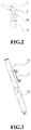
- FIG. 3 is a front structural diagram of a telescopic thigh bar of the lower limb exoskeleton system of the present invention
- FIG. 4 is a structural diagram of a knee joint movement mechanism of the lower limb exoskeleton system of the present invention.
- FIG. 5 is a structural diagram of a foot jump-down cushioning mechanism of the lower limb exoskeleton system of the present invention.
- FIG. 6 is a diagram of a control module and an electromagnet of the present invention.
- FIG. 7 is a diagram for virtual wearing of the lower limb exoskeleton system of the present invention.
- a lower limb exoskeleton system having jump-down cushioning function comprises a back frame 1 , two hip joint movement mechanisms 2 , two telescopic thigh bars 7 , two knee joint movement mechanisms 4 , two shank bars 8 , two foot jump-down cushioning mechanisms 5 , a waist binding frame 6 , two upper leg binding frames 3 and two lower leg binding frames 17 .
- the waist binding frame 6 is arranged on an inner side of a horizontal part of the back frame 1 , the upper leg binding frames 3 are arranged on the telescopic thigh bars 7 respectively, and the lower leg binding frames 17 are arranged on the shank bars 8 respectively.
- Each of the hip joint movement mechanisms 2 consists of an abduction and adduction moving piece 9 , a flexion and extension moving piece 10 and an upper thigh bar connecting frame 11 .
- Top ends of the abduction and adduction moving pieces 9 are connected with the protruding ends of the back frame 1 through bolts respectively, and bottom ends of the abduction and adduction moving pieces 9 are connected with top ends of the flexion and extension moving pieces 10 via two first pins respectively to realize the abduction and adduction movements of the lower limb exoskeleton system.
- the bottom ends of the flexion and extension moving pieces 10 are connected with top ends of the upper thigh bar connecting frames 11 via two second pins respectively to form a rotating pair to realize flexion and extension movements of the hip joint movement mechanism 2 .
- Each of the first pins and each of the second pins are perpendicular to each other.
- the hip joint movement mechanism 2 of the present invention has two degrees of freedom.
- Each of the telescopic thigh bars 7 consists of an upper thigh bar 12 and a lower thigh bar 13 .
- the upper thigh bar 12 and the lower thigh bar 13 are both made of aluminum tubes, three threaded through holes are formed on an upper end of each of the lower thigh bars 13 in one row, and the upper ends of the lower thigh bars 13 are connected with bottom ends of the upper thigh bars 12 via the threaded through holes and bolts respectively to realize the stepped length adjustment of the telescopic thigh bar 7 .
- Top ends of the upper thigh bars 12 are threadedly connected with the upper thigh bar connecting frames 11 respectively, and the upper leg binding frames 3 are connected to middle parts of outer side surfaces of the upper thigh bars 12 through bolts respectively.
- Two through holes are formed on an ear plate at a bottom end of each of the lower thigh bars 13 in one row.
- Each of the knee joint movement mechanisms 4 consists of a first lower thigh bar connecting frame 14 and a second lower thigh bar connecting frame 14 A, a knee joint rotating piece 15 , a harmonic reducer 16 and a motor 18 .
- the first lower thigh bar connecting frames 14 are connected with the bottom ends of the lower thigh bar 13 through bolts respectively
- the second lower thigh bar connecting frames 14 A are connected with the bottom ends of lower thigh bars 13 through bolts respectively
- the first lower thigh bar connecting frames 14 are connected with flexible gears of the harmonic reducers 16 and the motors 18 respectively.
- the harmonic reducers 16 are located on inner sides of the first lower thigh bar connecting frames 14 respectively, the motors 18 are located on outer sides of the first lower thigh bar connecting frames 14 respectively, harmonic generators of the harmonic reducers 16 are connected with output shafts of the motors 18 respectively, and steel output gears of the harmonic reducers 16 are connected with the knee joint rotating pieces 15 respectively. Bottom ends of the knee joint rotating pieces 15 are connected with top ends of the shank bars 8 through bolts respectively.
- Fixed-angle notch bosses 141 are arranged on connecting sides of the first and second lower thigh bar connecting frames 14 , 14 A, and the connecting sides of the first and second lower thigh bar connecting frames 14 , 14 A are connected with the knee joint rotating pieces 15 .
- the knee joint rotating pieces 15 When the knee joint rotating pieces 15 rotate to front and rear limit positions, the knee joint rotating pieces 15 abut against the fixed-angle notch bosses 141 on the first and second lower thigh bar connecting frames 14 , 14 A to limit a moving range of the knee joint movement mechanisms 4 .
- Two angle sensors are mounted on the motors 18 respectively to prevent the flexion and extension movements of the knee joint movement mechanisms 4 from out of normal range.
- the motors 18 output certain torque to drive the lower limb exoskeleton system to assist in the movement of human knee joints according to the movement principles and characteristics of human lower limbs in normal walking.
- Each of the foot jump-down cushioning mechanisms 5 consists of an electromagnet 19 , an electromagnet fixing frame 20 , two traction ropes 21 , two clamps 22 , a rubber mat 23 , a shell 24 , a moving sleeve 25 , a cushioning spring 26 , two reset springs 27 and a control module 29 .
- Top ends of the shells 24 are connected with bottom ends of the shank bars 8 through bolts respectively, the moving sleeves 25 are arranged in inner sides of the shells 24 respectively.
- Each of the shells 24 consists of two semicircular shells, protruding flanges are arranged on end surfaces of the semicircular shells, and the two semicircular shells are fixedly mounted through the protruding flanges and the bolts to form the each of shells 24 .
- the cushioning springs 26 are arranged in the moving sleeves 25 respectively, an inner stop block is arranged at a bottom end of an inner wall of each of the shells 24 , an outer stop block is arranged at a top end of an outer wall of each of the moving sleeves 25 , the inner stop block of each of the shells 24 and the outer stop block of each of the moving sleeve 25 are in buckling to prevent each of the moving sleeves 25 from moving out of each of the shells 24 , and top ends of the cushioning springs 26 are abutted against inner limiting plates in the shells 24 respectively.
- the clamps 22 are arranged on outer side surfaces of lower middle parts of the shells 24 respectively, middle parts of the clamps 22 are hinged with the shells 24 respectively, two bosses are arranged on an outer side surface of an upper part of each of the shells, and the reset springs 27 are arranged between side surfaces at top ends of the clamps 22 and the bosses of the shells 24 respectively.
- the reset springs 27 are biased to a compressed state, and the clamps 22 are pushed by the spring force of the reset springs 27 during jumping down so that bottom ends of the clamps 22 tightly press against lower end surfaces of the moving sleeves 25 .
- the top ends of the clamps 22 are connected with bottom ends of the traction ropes 21 respectively, and top ends of the traction ropes 21 are connected with the electromagnets 19 respectively.
- the electromagnets 19 are push-pull frame DC electromagnets and are arranged on the electromagnet fixing frames 20 through bolts respectively, and the electromagnet fixing frames 20 are fixed on the shank bars 8 through bolts respectively.
- Bending parts at the bottom ends of the clamps 22 are connected with bottom ends of the moving sleeves 25 respectively to limit the position of the moving sleeves 25 , and the bending parts at the bottom ends of the clamps 22 form a 90-degree angle with main body parts of the clamps 22 .
- the bottom ends of the moving sleeves 25 are connected with the rubber mats 23 through bolts respectively, and bonding surfaces between the rubber mats 23 and the moving sleeves 25 are bound through rubber-metal adhesive glue.
- Grooves 28 are formed on the rubber mats 23 so that the clamps 22 have enough movement space in expansion.
- the control modules 28 are connected with the electromagnets 19 respectively.
- Each of the control modules 29 comprises an upper computer 291 , a wireless communication module 292 , a control panel 293 and a relay 294 .
- the upper computers 291 are connected with the control panels 293 through the wireless communication modules 292 respectively, the control panels 293 are electrically connected with the relays 294 respectively, and the relays 294 are electrically connected with the electromagnets 19 respectively.
- the control panels 293 are mainly used for controlling the power-on and power-off of the push-pull frame DC electromagnets 19 respectively to further control the opening and closing of the clamps 22 .
- Each of the upper computers 291 is an ordinary notebook computer
- each of the wireless communication modules 292 is ZigBee wireless communication module
- each of the control panels 293 is arduino mega2560 control panel
- each of the relay 294 is telesky24V relay.
- a method of using the lower limb exoskeleton system having jump-down cushioning function comprises the following steps:
- fixing the lower limb exoskeleton system to a wearer comprises attaching the back frame 1 of the lower limb exoskeleton system to a waist of the wearer through binding tapes and the waist binding frame 6 , attaching the telescopic thigh bars 7 to thighs of the wearer through the upper leg binding frames 3 and binding tapes, and attaching the shank bars 8 to shanks of the wearer through the lower leg binding frames 17 and binding tapes;
- the motors 18 in the knee joint movement mechanisms 4 outputting torque to control the walking action, and the harmonic reducers 16 converting rotation of the outer shafts of the motors 18 into flexion and extension movements of the knee joint movement mechanisms 4 , so that the hip joint movement mechanisms 2 are driven to passively follow the wearer to move;
- the upper computers 291 sending instructions to the control panels 293 via the wireless communication modules 292 , output pins of the control panels 293 controlling the relays 294 to be connected, electrifying the push-pull frame DC electromagnets 19 to be connected to drag the traction ropes 21 and open the clamps 22 , and the cushioning springs 26 compressed in the shells 24 pushing the moving sleeves 25 to a limit position under the action of spring force;
- the upper computers 291 sending instructions to control the control panels 293 , and the output pins of the control panels 293 controlling the relays 294 to be disconnected so as to disconnect the push-pull frame DC electromagnets 19 and loosen the traction ropes 21 ;
- the energy absorbed by the skeletal muscle and joint system in the cushioning process is limited and set as W 1 max .
- W 1 W 1 max needs to be satisfied so as to ensure the safety of human body in jumping down, that is W 1 needs to be reduced.
- W 1 can be reduced by increasing the cushioning ability of the lower limb exoskeleton system, i.e. W 2 .
- an elastic energy absorbing element in the foot jump-down cushioning mechanisms are springs.
- the stiffness factor of the springs is set as K
- the compression displacement of the springs in one-time jumping down process is ⁇ x
- W spring 2 ⁇ x 2
- the cushioning ability of the lower limb exoskeleton system can be adjusted by adjusting the stiffness of the springs in the foot jump-down cushioning mechanisms to meet different use requirements, so that the human body can be cushioned and protected when the wearer jumps down.
Landscapes
- Health & Medical Sciences (AREA)
- Life Sciences & Earth Sciences (AREA)
- Veterinary Medicine (AREA)
- Public Health (AREA)
- General Health & Medical Sciences (AREA)
- Animal Behavior & Ethology (AREA)
- Pain & Pain Management (AREA)
- Rehabilitation Therapy (AREA)
- Physical Education & Sports Medicine (AREA)
- Epidemiology (AREA)
- Engineering & Computer Science (AREA)
- Mechanical Engineering (AREA)
- Robotics (AREA)
- Rehabilitation Tools (AREA)
- Transplantation (AREA)
- Oral & Maxillofacial Surgery (AREA)
- Cardiology (AREA)
- Biomedical Technology (AREA)
- Heart & Thoracic Surgery (AREA)
- Vascular Medicine (AREA)
- Orthopedic Medicine & Surgery (AREA)
Abstract
Description
W g =W 1 +W 2
W 1 =W g −W 2
W 2=2W spring =KΔx 2
W 1 =W g −KΔx 2
Claims (6)
Applications Claiming Priority (3)
| Application Number | Priority Date | Filing Date | Title |
|---|---|---|---|
| CN201910032241.7 | 2019-01-14 | ||
| CN201910032241.7A CN109454632B (en) | 2019-01-14 | 2019-01-14 | A lower extremity exoskeleton system with jump buffer function |
| PCT/CN2019/072588 WO2020147138A1 (en) | 2019-01-14 | 2019-01-22 | Lower limb exoskeleton system with jump-down buffering function |
Publications (2)
| Publication Number | Publication Date |
|---|---|
| US20200281745A1 US20200281745A1 (en) | 2020-09-10 |
| US11071675B2 true US11071675B2 (en) | 2021-07-27 |
Family
ID=65616416
Family Applications (1)
| Application Number | Title | Priority Date | Filing Date |
|---|---|---|---|
| US16/605,698 Active 2039-04-30 US11071675B2 (en) | 2019-01-14 | 2019-01-22 | Lower limb exoskeleton system having jump-down cushioning function and method of using the same |
Country Status (3)
| Country | Link |
|---|---|
| US (1) | US11071675B2 (en) |
| CN (1) | CN109454632B (en) |
| WO (1) | WO2020147138A1 (en) |
Families Citing this family (32)
| Publication number | Priority date | Publication date | Assignee | Title |
|---|---|---|---|---|
| CN110170985A (en) * | 2019-05-14 | 2019-08-27 | 北京铁甲钢拳科技有限公司 | A kind of exoskeleton system |
| CN110296635A (en) * | 2019-07-29 | 2019-10-01 | 广州钛敌科装备科技发展有限责任公司 | Shield device and shield backrest |
| CN113002656B (en) * | 2019-12-20 | 2022-08-02 | 北京大艾机器人科技有限公司 | Length-adjustable lower limb structure and robot lower limb using same |
| CN111941395B (en) * | 2020-08-11 | 2022-07-19 | 北京机械设备研究所 | Buffering ectoskeleton based on tertiary buffer gear |
| CN112060060B (en) * | 2020-09-22 | 2024-02-13 | 南京理工大学 | Active and passive hybrid driven lower limb power-assisted exoskeleton robot and control method |
| CN112168611A (en) * | 2020-09-30 | 2021-01-05 | 天津大学 | An active exoskeleton for lower extremity training in surface weightlessness |
| CN112603612B (en) * | 2020-12-25 | 2025-04-25 | 电子科技大学中山学院 | Bionic lower limbs |
| CN112621729B (en) * | 2020-12-28 | 2024-09-20 | 华南理工大学 | A knee joint assist device based on energy recovery |
| CN112999020B (en) * | 2021-02-19 | 2023-09-15 | 陕西捷赛达医疗设备有限公司 | Exoskeleton robot |
| CN112914955A (en) * | 2021-03-03 | 2021-06-08 | 上海冉擎机械设备有限公司 | Medical exoskeleton robot |
| CN112975914A (en) * | 2021-03-16 | 2021-06-18 | 北京工业大学 | Sole control type lower limb energy storage boosting mechanism |
| CN115139282B (en) * | 2021-03-30 | 2025-04-25 | 广州视源电子科技股份有限公司 | Bionic knee joint exoskeleton structure and exoskeleton robot |
| CN113133898B (en) * | 2021-04-26 | 2023-01-13 | 北京工业大学 | Lower limb rehabilitation exoskeleton mechanism with flexible joints |
| CN113370177B (en) * | 2021-05-17 | 2024-06-18 | 武汉理工大学 | A wearable human-machine collaborative assembly gripper for automobile front-end module assembly |
| CN113520786B (en) * | 2021-06-10 | 2022-09-13 | 唐山海容机器人应用技术研究院 | Wearable lower limb exoskeleton auxiliary walking robot |
| CN113246179A (en) * | 2021-06-15 | 2021-08-13 | 军事科学院系统工程研究院军需工程技术研究所 | Passive gravity compensation hip joint for heavy-load lower limb assistance exoskeleton and robot |
| CN113814962B (en) * | 2021-09-27 | 2022-12-13 | 国网江苏省电力有限公司扬州供电分公司 | Intelligent climbing exoskeleton system |
| JP7472893B2 (en) * | 2021-11-12 | 2024-04-23 | トヨタ自動車株式会社 | Component fastening structure and mounting fixture |
| CN113910205B (en) * | 2021-12-14 | 2022-03-11 | 深圳市迈步机器人科技有限公司 | Lower limb exoskeleton power assisting system |
| CN114310943B (en) * | 2021-12-23 | 2023-08-01 | 杭州太希智能科技有限公司 | Joint module, leg lifting state free bending's helping hand low limbs ectoskeleton and whole body ectoskeleton |
| CN114534172B (en) * | 2022-02-17 | 2022-09-27 | 华中科技大学 | Passive load supporting device with automatic power-assisted phase switching function |
| CN114698974A (en) * | 2022-03-07 | 2022-07-05 | 覃俊欢 | Infant walking auxiliary device |
| CN114800441B (en) * | 2022-03-19 | 2023-07-07 | 中国人民解放军空军军医大学 | Heterogeneous knee joint of lower extremity exoskeleton based on parallel elastomers |
| CN114712171B (en) * | 2022-04-06 | 2023-12-26 | 吉林农业大学 | A wearable bionic leg and foot mechanism used to assist the disabled in walking |
| US20230380763A1 (en) * | 2022-05-05 | 2023-11-30 | Tau Orthopedics, Inc. | Physical therapy monitoring system |
| USD1010141S1 (en) * | 2022-06-08 | 2024-01-02 | Wandercraft | Exoskeleton walking aid |
| CN115245446B (en) * | 2022-07-20 | 2024-09-20 | 合肥工业大学 | Knee joint exoskeleton with rigidity adjusting and energy recovering functions and training method thereof |
| CN115488861A (en) * | 2022-10-14 | 2022-12-20 | 塞伯睿机器人技术(南京)有限公司 | Passive lower limb exoskeleton |
| CN115582825B (en) * | 2022-12-12 | 2024-03-15 | 杭州智元研究院有限公司 | Passive lower limb exoskeleton |
| WO2025085465A1 (en) * | 2023-10-17 | 2025-04-24 | The Government Of The United States, As Represented By The Secretary Of The Army | Exoskeleton device |
| CN119871342B (en) * | 2025-01-14 | 2025-08-19 | 无锡商业职业技术学院 | Intelligent exoskeleton robot |
| CN119745659B (en) * | 2025-03-07 | 2025-05-13 | 杭州智元研究院有限公司 | Clutch type muscle-like booster device with knee joint variable stiffness is adjustable |
Citations (18)
| Publication number | Priority date | Publication date | Assignee | Title |
|---|---|---|---|---|
| EP0229537A1 (en) * | 1985-10-30 | 1987-07-22 | Jean-Louis Chareire | Mechanical aid for leg-powered motion |
| US20020094919A1 (en) * | 2000-07-26 | 2002-07-18 | Rennex Brain G. | Energy-efficient running aid |
| US20020177906A1 (en) * | 1998-04-10 | 2002-11-28 | Phillips Van L. | Active shock module prosthesis |
| DE102004016294B3 (en) * | 2004-04-02 | 2005-08-25 | Hurnik, Dieter, Dipl.-Ing. (FH) | Jumping device for sports exercises includes energy converter with gas cushion in cylinder and with support faces of foot rests about forty centimetres below upper lid of cylinder |
| US20060052731A1 (en) * | 2004-09-07 | 2006-03-09 | Honda Motor Co., Ltd. | Walking assistance device having a pelvis support member that is easy to wear |
| US20090143869A1 (en) | 2007-11-29 | 2009-06-04 | Chia-Pao Cheng | Anti-shock artificial knee joint structure |
| US20110040216A1 (en) * | 2005-03-31 | 2011-02-17 | Massachusetts Institute Of Technology | Exoskeletons for running and walking |
| JP3185908U (en) * | 2013-03-26 | 2013-09-12 | 泰治 志渡澤 | Cane to assist walking |
| CN105438306A (en) | 2015-11-25 | 2016-03-30 | 北京航空航天大学 | Bionic locust jumping robot with buffer performance |
| CN105479438A (en) | 2015-12-29 | 2016-04-13 | 哈尔滨工业大学 | Exoskeleton with function of assisting in jumping through energy storage of springs |
| CN105904439A (en) | 2016-05-19 | 2016-08-31 | 成都奥特为科技有限公司 | Gait-sensing flexible foot device with rigidity self-adjusting function |
| CN105965483A (en) | 2016-06-30 | 2016-09-28 | 西南交通大学 | Lower Limb Assisted Exoskeleton Robot |
| CN106005079A (en) | 2016-05-24 | 2016-10-12 | 浙江大学 | Single-leg robot jumping mechanism with active ankle joint and bionic foot |
| CN106726363A (en) | 2017-03-13 | 2017-05-31 | 东北大学 | A kind of wearable bionical hydraulic pressure lower limb rehabilitation walk help mechanical device |
| CN107049713A (en) | 2017-03-13 | 2017-08-18 | 东北大学 | Wearable lower limb rehabilitation walk help mechanical device |
| CN108272598A (en) * | 2017-12-17 | 2018-07-13 | 青岛万祥如光机械技术研究有限公司 | A kind of standing support device |
| CN109070340A (en) * | 2016-04-15 | 2018-12-21 | 麦可尼股份有限公司 | walking aids |
| US20200206065A1 (en) * | 2018-12-27 | 2020-07-02 | Chin-Sung Yang | Assistant apparatus for degenerative joint |
Family Cites Families (4)
| Publication number | Priority date | Publication date | Assignee | Title |
|---|---|---|---|---|
| US9004201B2 (en) * | 2012-04-18 | 2015-04-14 | Board Of Trustees Of Michigan State University | Jumping robot |
| CN103932870B (en) * | 2014-05-04 | 2016-04-13 | 浙江大学 | Bionic Design lower limb rehabilitation training ectoskeleton |
| CN107696023A (en) * | 2017-10-12 | 2018-02-16 | 长沙展朔轩兴信息科技有限公司 | Expansion muscle driven double-flexibility cuts with scissors the hopping robot in joint |
| CN107811819A (en) * | 2017-11-23 | 2018-03-20 | 航天科工智能机器人有限责任公司 | A kind of wearable lower limb rehabilitation robot |
-
2019
- 2019-01-14 CN CN201910032241.7A patent/CN109454632B/en not_active Expired - Fee Related
- 2019-01-22 US US16/605,698 patent/US11071675B2/en active Active
- 2019-01-22 WO PCT/CN2019/072588 patent/WO2020147138A1/en not_active Ceased
Patent Citations (18)
| Publication number | Priority date | Publication date | Assignee | Title |
|---|---|---|---|---|
| EP0229537A1 (en) * | 1985-10-30 | 1987-07-22 | Jean-Louis Chareire | Mechanical aid for leg-powered motion |
| US20020177906A1 (en) * | 1998-04-10 | 2002-11-28 | Phillips Van L. | Active shock module prosthesis |
| US20020094919A1 (en) * | 2000-07-26 | 2002-07-18 | Rennex Brain G. | Energy-efficient running aid |
| DE102004016294B3 (en) * | 2004-04-02 | 2005-08-25 | Hurnik, Dieter, Dipl.-Ing. (FH) | Jumping device for sports exercises includes energy converter with gas cushion in cylinder and with support faces of foot rests about forty centimetres below upper lid of cylinder |
| US20060052731A1 (en) * | 2004-09-07 | 2006-03-09 | Honda Motor Co., Ltd. | Walking assistance device having a pelvis support member that is easy to wear |
| US20110040216A1 (en) * | 2005-03-31 | 2011-02-17 | Massachusetts Institute Of Technology | Exoskeletons for running and walking |
| US20090143869A1 (en) | 2007-11-29 | 2009-06-04 | Chia-Pao Cheng | Anti-shock artificial knee joint structure |
| JP3185908U (en) * | 2013-03-26 | 2013-09-12 | 泰治 志渡澤 | Cane to assist walking |
| CN105438306A (en) | 2015-11-25 | 2016-03-30 | 北京航空航天大学 | Bionic locust jumping robot with buffer performance |
| CN105479438A (en) | 2015-12-29 | 2016-04-13 | 哈尔滨工业大学 | Exoskeleton with function of assisting in jumping through energy storage of springs |
| CN109070340A (en) * | 2016-04-15 | 2018-12-21 | 麦可尼股份有限公司 | walking aids |
| CN105904439A (en) | 2016-05-19 | 2016-08-31 | 成都奥特为科技有限公司 | Gait-sensing flexible foot device with rigidity self-adjusting function |
| CN106005079A (en) | 2016-05-24 | 2016-10-12 | 浙江大学 | Single-leg robot jumping mechanism with active ankle joint and bionic foot |
| CN105965483A (en) | 2016-06-30 | 2016-09-28 | 西南交通大学 | Lower Limb Assisted Exoskeleton Robot |
| CN106726363A (en) | 2017-03-13 | 2017-05-31 | 东北大学 | A kind of wearable bionical hydraulic pressure lower limb rehabilitation walk help mechanical device |
| CN107049713A (en) | 2017-03-13 | 2017-08-18 | 东北大学 | Wearable lower limb rehabilitation walk help mechanical device |
| CN108272598A (en) * | 2017-12-17 | 2018-07-13 | 青岛万祥如光机械技术研究有限公司 | A kind of standing support device |
| US20200206065A1 (en) * | 2018-12-27 | 2020-07-02 | Chin-Sung Yang | Assistant apparatus for degenerative joint |
Also Published As
| Publication number | Publication date |
|---|---|
| US20200281745A1 (en) | 2020-09-10 |
| WO2020147138A1 (en) | 2020-07-23 |
| CN109454632A (en) | 2019-03-12 |
| CN109454632B (en) | 2020-07-21 |
Similar Documents
| Publication | Publication Date | Title |
|---|---|---|
| US11071675B2 (en) | Lower limb exoskeleton system having jump-down cushioning function and method of using the same | |
| US20240424664A1 (en) | Exoskeleton device with improved actuation system | |
| Walsh et al. | Development of a lightweight, underactuated exoskeleton for load-carrying augmentation | |
| CN110202542B (en) | Exoskeleton | |
| CN112008701B (en) | Hip joint assistance exoskeleton system capable of supporting load in auxiliary mode | |
| US20180042803A1 (en) | Exoskeleton and Method of Transferring a Weight of a Load from the Exoskeleton to a Support Surface | |
| KR101735214B1 (en) | Lower-Body Assistance Robot | |
| CN111110519A (en) | A multi-sensing intelligent wearable lower limb exoskeleton robot | |
| CN103610568A (en) | Human-simulated external skeleton robot assisting lower limbs | |
| CN104758099B (en) | Lower limb assistance exoskeleton based on gravitational equilibrium | |
| CN212287630U (en) | A hip joint-assisted exoskeleton system that can assist weight-bearing | |
| CN111823217A (en) | A variable stiffness lower limb exoskeleton robot based on shape memory alloy | |
| CN113478466B (en) | A passive lower extremity exoskeleton with load conduction and walking energy saving | |
| CN111281744A (en) | Modular joint and wearable modular joint exoskeleton | |
| CN107174488A (en) | A kind of vola in-wheel driving self-balancing power exoskeleton for Patients of Spinal | |
| CN116673937A (en) | Integral type power-assisted exoskeleton device and power-assisted method | |
| CN113146579A (en) | Trans-joint load supporting device based on passive variable stiffness damper | |
| Kim et al. | Development of the heavy load transferring task oriented exoskeleton adapted by lower extremity using qausi-active joints | |
| CN120326576B (en) | Novel modularized whole body carrying system | |
| CN118181259B (en) | A powered knee joint exoskeleton walking aid device | |
| CN105943318A (en) | An assisting type ankle exoskeleton device | |
| Shrestha et al. | An affordable hip exoskeleton for assistance and rehabilitation: design, analysis, and fabrication | |
| Jin et al. | Design and preliminary evaluation of a lightweight, cable-driven hip exoskeleton for walking assistance | |
| CN108189011A (en) | A kind of human body walking walk helper | |
| CN219902167U (en) | Wearable human skeleton supporting device |
Legal Events
| Date | Code | Title | Description |
|---|---|---|---|
| AS | Assignment |
Owner name: NORTHEASTERN UNIVERSITY, CHINA Free format text: ASSIGNMENT OF ASSIGNORS INTEREST;ASSIGNORS:WANG, HONG;TANG, HAO;XI, HAILONG;AND OTHERS;REEL/FRAME:050741/0782 Effective date: 20190920 |
|
| FEPP | Fee payment procedure |
Free format text: ENTITY STATUS SET TO UNDISCOUNTED (ORIGINAL EVENT CODE: BIG.); ENTITY STATUS OF PATENT OWNER: SMALL ENTITY |
|
| FEPP | Fee payment procedure |
Free format text: ENTITY STATUS SET TO SMALL (ORIGINAL EVENT CODE: SMAL); ENTITY STATUS OF PATENT OWNER: SMALL ENTITY |
|
| STPP | Information on status: patent application and granting procedure in general |
Free format text: DOCKETED NEW CASE - READY FOR EXAMINATION |
|
| STPP | Information on status: patent application and granting procedure in general |
Free format text: NON FINAL ACTION MAILED |
|
| STPP | Information on status: patent application and granting procedure in general |
Free format text: RESPONSE TO NON-FINAL OFFICE ACTION ENTERED AND FORWARDED TO EXAMINER |
|
| STPP | Information on status: patent application and granting procedure in general |
Free format text: NOTICE OF ALLOWANCE MAILED -- APPLICATION RECEIVED IN OFFICE OF PUBLICATIONS |
|
| STPP | Information on status: patent application and granting procedure in general |
Free format text: PUBLICATIONS -- ISSUE FEE PAYMENT VERIFIED |
|
| STCF | Information on status: patent grant |
Free format text: PATENTED CASE |
|
| MAFP | Maintenance fee payment |
Free format text: PAYMENT OF MAINTENANCE FEE, 4TH YR, SMALL ENTITY (ORIGINAL EVENT CODE: M2551); ENTITY STATUS OF PATENT OWNER: SMALL ENTITY Year of fee payment: 4 |