US11056786B2 - Antenna system and mobile terminal - Google Patents
Antenna system and mobile terminal Download PDFInfo
- Publication number
- US11056786B2 US11056786B2 US16/524,084 US201916524084A US11056786B2 US 11056786 B2 US11056786 B2 US 11056786B2 US 201916524084 A US201916524084 A US 201916524084A US 11056786 B2 US11056786 B2 US 11056786B2
- Authority
- US
- United States
- Prior art keywords
- antenna
- antenna unit
- edge portion
- provided correspondingly
- ghz
- Prior art date
- Legal status (The legal status is an assumption and is not a legal conclusion. Google has not performed a legal analysis and makes no representation as to the accuracy of the status listed.)
- Expired - Fee Related
Links
Images


Classifications
-
- H—ELECTRICITY
- H01—ELECTRIC ELEMENTS
- H01Q—ANTENNAS, i.e. RADIO AERIALS
- H01Q5/00—Arrangements for simultaneous operation of antennas on two or more different wavebands, e.g. dual-band or multi-band arrangements
- H01Q5/30—Arrangements for providing operation on different wavebands
-
- H—ELECTRICITY
- H01—ELECTRIC ELEMENTS
- H01Q—ANTENNAS, i.e. RADIO AERIALS
- H01Q21/00—Antenna arrays or systems
- H01Q21/06—Arrays of individually energised antenna units similarly polarised and spaced apart
- H01Q21/061—Two dimensional planar arrays
-
- H—ELECTRICITY
- H01—ELECTRIC ELEMENTS
- H01Q—ANTENNAS, i.e. RADIO AERIALS
- H01Q1/00—Details of, or arrangements associated with, antennas
- H01Q1/12—Supports; Mounting means
- H01Q1/22—Supports; Mounting means by structural association with other equipment or articles
-
- H—ELECTRICITY
- H01—ELECTRIC ELEMENTS
- H01Q—ANTENNAS, i.e. RADIO AERIALS
- H01Q1/00—Details of, or arrangements associated with, antennas
- H01Q1/12—Supports; Mounting means
- H01Q1/22—Supports; Mounting means by structural association with other equipment or articles
- H01Q1/24—Supports; Mounting means by structural association with other equipment or articles with receiving set
- H01Q1/241—Supports; Mounting means by structural association with other equipment or articles with receiving set used in mobile communications, e.g. GSM
- H01Q1/242—Supports; Mounting means by structural association with other equipment or articles with receiving set used in mobile communications, e.g. GSM specially adapted for hand-held use
- H01Q1/243—Supports; Mounting means by structural association with other equipment or articles with receiving set used in mobile communications, e.g. GSM specially adapted for hand-held use with built-in antennas
-
- H—ELECTRICITY
- H01—ELECTRIC ELEMENTS
- H01Q—ANTENNAS, i.e. RADIO AERIALS
- H01Q21/00—Antenna arrays or systems
- H01Q21/28—Combinations of substantially independent non-interacting antenna units or systems
-
- H—ELECTRICITY
- H01—ELECTRIC ELEMENTS
- H01Q—ANTENNAS, i.e. RADIO AERIALS
- H01Q21/00—Antenna arrays or systems
- H01Q21/30—Combinations of separate antenna units operating in different wavebands and connected to a common feeder system
Definitions
- the present disclosure relates to the field of antenna technologies, and in particular, to an antenna system and a mobile terminal.
- wireless communication devices there is always a device that radiates electromagnetic energy into space and receives electromagnetic energy from space, and this device is an antenna.
- the role of the antenna is to transmit a digital or analog signal modulated onto a radio frequency (RF) frequency to a spatial wireless channel, or to receive a digital or analog signal modulated onto a RF frequency from a spatial wireless channel.
- RF radio frequency
- the existing wireless communication devices have more and more requirements on antenna operating bands, such that an increasingly complex internal antenna design is required.
- the existing wireless communication devices such as mobile phones, are becoming thinner, making the available space for the antenna smaller and smaller, which is difficult for the antenna to cover sufficient bands.
- FIG. 1 is a structural schematic diagram of an antenna system of the present disclosure when viewed in a first perspective
- FIG. 2 is a structural schematic diagram of an antenna system of the present disclosure when viewed in a second perspective.
- FIG. 3A is a return loss graph of a first antenna unit of an antenna system of the present disclosure
- FIG. 3B is an antenna efficiency graph of a first antenna unit of an antenna system of the present disclosure
- FIG. 4A is a return loss graph of a second antenna unit of an antenna system of the present disclosure.
- FIG. 4B is an antenna efficiency graph of a second antenna unit of an antenna system of the present disclosure.
- FIG. 5A is a return loss graph of a third antenna unit of an antenna system of the present disclosure.
- FIG. 5B is an antenna efficiency graph of a third antenna unit of an antenna system of the present disclosure.
- FIG. 6A is a return loss graph of a fourth antenna unit of an antenna system of the present disclosure.
- FIG. 6B is an antenna efficiency graph of a fourth antenna unit of an antenna system of the present disclosure.
- FIG. 7A is a return loss graph of a fifth antenna unit of an antenna system of the present disclosure.
- FIG. 7B is an antenna efficiency graph of a fifth antenna unit of an antenna system of the present disclosure.
- FIG. 8A is a return loss graph of a sixth antenna unit of an antenna system of the present disclosure.
- FIG. 8B is an antenna efficiency graph of a sixth antenna unit of an antenna system of the present disclosure.
- FIG. 9A is a return loss graph of a seventh antenna unit of an antenna system of the present disclosure.
- FIG. 9B is an antenna efficiency graph of a seventh antenna unit of an antenna system of the present disclosure.
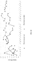
- FIG. 10 is an antenna efficiency graph of a diversity antenna and a main antenna that are formed by a first antenna unit and a third antenna unit of an antenna system of the present disclosure
- FIG. 11 is an antenna efficiency graph of a 3.3-3.6 GHz-4 ⁇ 4 MIMO formed by a first antenna unit, a fourth antenna unit, a fifth antenna unit, and a seventh antenna unit of the antenna system of the present disclosure.
- FIG. 12 is an antenna efficiency graph of a WIFI-2 ⁇ 2 MIMO formed by a second antenna unit and a sixth antenna unit of an antenna system of the present disclosure.
- an embodiment of the present disclosure provides an antenna system 100 , which can be applied to a mobile communication terminal such as a mobile phone.
- the antenna system 100 includes a non-metallic housing 1 .
- the non-metallic housing 1 includes a top edge portion 10 , a bottom edge portion 11 provided correspondingly to the top edge portion 10 , and a first long side edge portion 12 and a second long side edge portion 13 that connect the top edge portion 10 with the bottom edge portion 11 .
- the non-metallic housing 1 is a plastic housing and does not have a shielding effect on radio waves.
- the antenna system 100 further includes a top clearance region 14 provided correspondingly to the top edge portion 10 and a bottom clearance region 15 provided correspondingly to the bottom edge portion 11 .
- the top clearance region 14 has a width of 6.2 mm
- the bottom clearance region 15 has a width of 3.8 mm.
- the antenna system 100 further includes a circuit board 16 provided in the non-metallic housing 1 .
- the circuit board 16 is provided with a system ground 160 .
- a width of the clearance region 14 refers to a distance from the system ground 160 on the circuit board 16 to the bottom edge portion 11 or the top edge portion 10 of the non-metallic housing 1 along a length direction of the non-metallic housing 1 .
- the antenna system 100 further includes a first antenna unit 2 , a second antenna unit 3 , a third antenna unit 4 , a fourth antenna unit 5 , a fifth antenna unit 6 , a sixth antenna unit 7 and a seventh antenna unit 8 , which are arranged to correspond to the periphery of the non-metallic housing 1 and are spaced apart from each other.
- the antenna system 100 can cover multiple bands.
- the structure of each antenna unit can be designed to be simpler so as to reduce design cost.
- the first antenna unit 2 is provided correspondingly to the top edge portion 10 .
- the first antenna unit 2 is a 3.3-3.6 GHz-4 ⁇ 4 MIMO antenna and has coverage bands of 790-960 MHz, 1710-2690 MHz and 3.3-3.6 GHz.
- the return loss and antenna efficiency in the coverage bands of the first antenna unit 2 are illustrated in FIGS. 3A and B.
- the second antenna unit 3 is provided correspondingly to the top position and spaced apart from the first antenna unit.
- the second antenna unit 3 is a WIFI-2 ⁇ 2 MIMO antenna, and has coverage bands of 1550-1620 MHz, 2400-2500 MHz and 5.15-5.85 GHz.
- the return loss and antenna efficiency in the coverage bands of the second antenna unit 3 are illustrated in FIGS. 4A and B.
- the third antenna unit 4 is provided correspondingly to the bottom position. Specifically, the third antenna unit 4 is a main antenna, and has coverage bands of 790-960 MHz and 1710-2690 MHz. The return loss and antenna efficiency in the coverage bands of the third antenna unit 4 are illustrated in FIGS. 5A and B.
- the fourth antenna unit 5 is provided correspondingly to the first long side edge portion and close to the second antenna unit. Specifically, the fourth antenna unit 5 is a 3.3-3.6 GHz-4 ⁇ 4 MIMO antenna, and has a coverage band of 3.3-3.6 GHz. The return loss and antenna efficiency in the coverage band of fourth antenna unit 5 are illustrated in FIGS. 6A and B.
- the fifth antenna unit 6 is provided correspondingly to the first long side edge portion and close to the third antenna unit. Specifically, the fifth antenna unit 6 is a 3.3-3.6 GHz-4 ⁇ 4 MIMO antenna, and has a coverage band of 3.3-3.6 GHz. The return loss and antenna efficiency in the coverage band of fifth antenna unit 6 are illustrated in FIGS. 7A and B.
- the sixth antenna unit 7 is provided correspondingly to the second long side edge portion and close to the first antenna unit.
- the sixth antenna unit 7 is a WIFI-2 ⁇ 2 MIMO antenna, and has coverage bands of 2400-2500 MHz and 5.15-5.85 GHz.
- the return loss and antenna efficiency in the coverage bands of sixth antenna unit 7 are illustrated in FIGS. 8A and B.
- the seventh antenna unit 8 is provided correspondingly to the second long side edge portion and close to the third antenna unit. Specifically, the seventh antenna unit 8 is a 3.3-3.6 GHz-4 ⁇ 4 MIMO antenna, and has a coverage band of 3.3-3.6 GHz. The return loss and antenna efficiency in the coverage band of seventh antenna unit 8 are illustrated in FIGS. 9A and B.
- the first antenna unit 2 , the fourth antenna unit 5 , the fifth antenna unit 6 , and the seventh antenna unit 8 that are included in the antenna system 10 provided by the present disclosure are all 3.3-3.6 GHz-4 ⁇ 4 MIMO antennas, and each of them covers a band of 3.5 G (3.3-3.6 GHz).
- the average antenna efficiency of each antenna unit is shown in Table 1 below. Reference can be made to FIG. 11 for details.
- the second antenna unit 3 and the sixth antenna unit 7 that are included in the antenna system 10 provided by the present disclosure are both WIFI-2 ⁇ 2 MIMO antennas, and each of them covers bands of WIFI 2.4 G (2.4-2.5 GHz) and WIFI 5 G (5.15-5.85 GHz). Moreover, the second antenna unit 3 includes a GPS band, and the average antenna efficiency of each antenna unit is shown in Table 2 below. Reference can be made to FIG. 12 for details.
- Second antenna unit Sixth antenna unit 1550-1620 39% 2400-2500 31% 19% 5150-5850 23% 32%
- the first antenna unit 2 and the third antenna unit 4 that are included in the antenna system 10 provided by the present disclosure both cover bands of (790-960 MHz, 1710-2690 MHz).
- the first antenna unit 2 is a diversity antenna.
- the third antenna unit 4 is a main antenna. 2G, 3G and 4G mobile communications can be achieved by providing the second antenna unit 2 and the third antenna unit 4 .
- the average antenna efficiency of each antenna unit is shown in Table 3 below. Reference can be made to FIG. 10 for details.
- the antenna system 100 provided by the present disclosure, by separately providing 7 antenna units, achieves that each antenna unit covers fewer bands, thereby reducing the design difficulty and cost of each antenna unit.
- each antenna unit covers fewer bands, thereby reducing the design difficulty and cost of each antenna unit.
- the antenna system covers multiple bands simply by designing operating bands and the number of the multiple antenna units as needed.
- the present disclosure also provides a mobile terminal (not shown), and the mobile terminal includes the antenna system 100 described above.
- the antenna system provided by the present disclosure by providing seven antenna units on the periphery of the non-metallic housing, achieves 3.3-3.6 GHz-4 ⁇ 4 MIMO, WIFI-2 ⁇ 2 MIMO, GPS, and 2G, 3G and 4G mobile communications.
Landscapes
- Engineering & Computer Science (AREA)
- Computer Networks & Wireless Communication (AREA)
- Support Of Aerials (AREA)
- Variable-Direction Aerials And Aerial Arrays (AREA)
- Telephone Set Structure (AREA)
Abstract
Description
| TABLE 1 | ||
| Frequency (MHz) | 3300-3600 | |
| Seventh antenna unit | 32% | |
| |
30% | |
| Fourth antenna unit | 23% | |
| First antenna unit | 34% | |
| TABLE 2 | ||
| Frequency (MHz) | Second antenna unit | Sixth antenna unit |
| 1550-1620 | 39% | |
| 2400-2500 | 31% | 19% |
| 5150-5850 | 23% | 32% |
| TABLE 3 | ||
| Frequency (MHz) | Third antenna unit | First antenna unit |
| 790-960 | 26% | 14% |
| 1710-2170 | 34% | 27% |
| 2300-2690 | 38% | 25% |
| 3300-3600 | 34% | |
Claims (6)
Applications Claiming Priority (2)
| Application Number | Priority Date | Filing Date | Title |
|---|---|---|---|
| CN201810880128.XA CN109149067B (en) | 2018-08-03 | 2018-08-03 | Antenna system and mobile terminal |
| CN201810880128.X | 2018-08-03 |
Publications (2)
| Publication Number | Publication Date |
|---|---|
| US20200044339A1 US20200044339A1 (en) | 2020-02-06 |
| US11056786B2 true US11056786B2 (en) | 2021-07-06 |
Family
ID=64791436
Family Applications (1)
| Application Number | Title | Priority Date | Filing Date |
|---|---|---|---|
| US16/524,084 Expired - Fee Related US11056786B2 (en) | 2018-08-03 | 2019-07-28 | Antenna system and mobile terminal |
Country Status (3)
| Country | Link |
|---|---|
| US (1) | US11056786B2 (en) |
| CN (1) | CN109149067B (en) |
| WO (1) | WO2020024656A1 (en) |
Families Citing this family (8)
| Publication number | Priority date | Publication date | Assignee | Title |
|---|---|---|---|---|
| CN208589528U (en) * | 2018-08-03 | 2019-03-08 | 瑞声科技(南京)有限公司 | Millimeter wave array antenna framework |
| CN109149067B (en) * | 2018-08-03 | 2021-07-06 | 瑞声精密制造科技(常州)有限公司 | Antenna system and mobile terminal |
| WO2021000081A1 (en) * | 2019-06-29 | 2021-01-07 | 瑞声声学科技(深圳)有限公司 | Antenna module and mobile terminal |
| WO2021000079A1 (en) * | 2019-06-29 | 2021-01-07 | 瑞声声学科技(深圳)有限公司 | Antenna module and mobile terminal |
| WO2021000183A1 (en) * | 2019-06-30 | 2021-01-07 | 瑞声声学科技(深圳)有限公司 | Antenna module and mobile terminal |
| CN111029743A (en) * | 2019-12-10 | 2020-04-17 | 瑞声精密电子沭阳有限公司 | Antenna module and mobile terminal |
| CN110994156B (en) * | 2019-12-20 | 2021-06-15 | 惠州Tcl移动通信有限公司 | Antenna assembly and mobile terminal |
| CN119211403A (en) * | 2023-06-25 | 2024-12-27 | 华为技术有限公司 | Shell assembly and terminal device |
Citations (10)
| Publication number | Priority date | Publication date | Assignee | Title |
|---|---|---|---|---|
| US20100127949A1 (en) * | 2008-11-26 | 2010-05-27 | Hitachi Cable, Ltd. | Mobile Communication base station antenna |
| US20100227646A1 (en) * | 2009-03-03 | 2010-09-09 | Hitachi Cable, Ltd. | Mobile communication base station antenna |
| US20180316088A1 (en) * | 2015-12-29 | 2018-11-01 | Huawei Technologies Co., Ltd. | Antenna and communications device |
| US20180366812A1 (en) * | 2017-06-20 | 2018-12-20 | Samsung Electronics Co., Ltd. | Electronic device comprising antenna |
| US20190214722A1 (en) * | 2018-01-05 | 2019-07-11 | Wispry, Inc. | Hybrid high gain antenna systems, devices, and methods |
| US20190229413A1 (en) * | 2018-01-24 | 2019-07-25 | Samsung Electronics Co., Ltd. | Antenna structure and electronic device comprising antenna structure |
| US20200021015A1 (en) * | 2018-07-13 | 2020-01-16 | Samsung Electronics Co., Ltd. | Antenna structure and electronic device comprising antenna |
| US20200044339A1 (en) * | 2018-08-03 | 2020-02-06 | AAC Technologies Pte. Ltd. | Antenna system and mobile terminal |
| US20200076055A1 (en) * | 2017-05-30 | 2020-03-05 | Samsung Electronics Co., Ltd. | Antenna array and electronic device including antenna arrray |
| US20200153115A1 (en) * | 2018-11-09 | 2020-05-14 | Samsung Electronics Co., Ltd. | Antenna having radiation structure of given direction and electronic device including same |
Family Cites Families (12)
| Publication number | Priority date | Publication date | Assignee | Title |
|---|---|---|---|---|
| JP2005109895A (en) * | 2003-09-30 | 2005-04-21 | Taiyo Yuden Co Ltd | Radio communication apparatus |
| KR101484749B1 (en) * | 2008-08-19 | 2015-01-21 | 삼성전자주식회사 | An antenna apparatus |
| EP2323217B1 (en) * | 2009-11-13 | 2014-04-30 | BlackBerry Limited | Antenna for multi mode mimo communication in handheld devices |
| CN204577586U (en) * | 2015-03-09 | 2015-08-19 | 上海德门电子科技有限公司 | Multi-antenna structure on a kind of plastic casing |
| CN105049560B (en) * | 2015-07-13 | 2018-06-19 | 中国计量学院 | Mobile phone diversity system and mobile phone based on directional aerial |
| CN204886955U (en) * | 2015-09-14 | 2015-12-16 | 广东欧珀移动通信有限公司 | Antenna device and mobile terminal |
| CN105552540B (en) * | 2015-12-22 | 2019-03-12 | 南京信息工程大学 | A compact and high isolation tri-band eight-unit MIMO mobile phone antenna |
| CN205211920U (en) * | 2015-12-25 | 2016-05-04 | 惠州硕贝德无线科技股份有限公司 | Cell -phone LTE antenna and MIMO antenna thereof |
| CN105680175B (en) * | 2016-01-11 | 2019-04-02 | 复旦大学 | A kind of compact multi-frequency band MIMO antenna for mobile phone |
| CN107623176A (en) * | 2017-08-18 | 2018-01-23 | 上海安费诺永亿通讯电子有限公司 | terminal MIMO antenna system |
| CN107819193B (en) * | 2017-11-21 | 2024-04-30 | 深圳市欢太科技有限公司 | Terminal |
| CN107919521B (en) * | 2017-12-28 | 2020-07-17 | Oppo广东移动通信有限公司 | Antenna units and terminal equipment |
-
2018
- 2018-08-03 CN CN201810880128.XA patent/CN109149067B/en active Active
-
2019
- 2019-05-17 WO PCT/CN2019/087452 patent/WO2020024656A1/en not_active Ceased
- 2019-07-28 US US16/524,084 patent/US11056786B2/en not_active Expired - Fee Related
Patent Citations (10)
| Publication number | Priority date | Publication date | Assignee | Title |
|---|---|---|---|---|
| US20100127949A1 (en) * | 2008-11-26 | 2010-05-27 | Hitachi Cable, Ltd. | Mobile Communication base station antenna |
| US20100227646A1 (en) * | 2009-03-03 | 2010-09-09 | Hitachi Cable, Ltd. | Mobile communication base station antenna |
| US20180316088A1 (en) * | 2015-12-29 | 2018-11-01 | Huawei Technologies Co., Ltd. | Antenna and communications device |
| US20200076055A1 (en) * | 2017-05-30 | 2020-03-05 | Samsung Electronics Co., Ltd. | Antenna array and electronic device including antenna arrray |
| US20180366812A1 (en) * | 2017-06-20 | 2018-12-20 | Samsung Electronics Co., Ltd. | Electronic device comprising antenna |
| US20190214722A1 (en) * | 2018-01-05 | 2019-07-11 | Wispry, Inc. | Hybrid high gain antenna systems, devices, and methods |
| US20190229413A1 (en) * | 2018-01-24 | 2019-07-25 | Samsung Electronics Co., Ltd. | Antenna structure and electronic device comprising antenna structure |
| US20200021015A1 (en) * | 2018-07-13 | 2020-01-16 | Samsung Electronics Co., Ltd. | Antenna structure and electronic device comprising antenna |
| US20200044339A1 (en) * | 2018-08-03 | 2020-02-06 | AAC Technologies Pte. Ltd. | Antenna system and mobile terminal |
| US20200153115A1 (en) * | 2018-11-09 | 2020-05-14 | Samsung Electronics Co., Ltd. | Antenna having radiation structure of given direction and electronic device including same |
Also Published As
| Publication number | Publication date |
|---|---|
| WO2020024656A1 (en) | 2020-02-06 |
| CN109149067B (en) | 2021-07-06 |
| CN109149067A (en) | 2019-01-04 |
| US20200044339A1 (en) | 2020-02-06 |
Similar Documents
| Publication | Publication Date | Title |
|---|---|---|
| US11056786B2 (en) | Antenna system and mobile terminal | |
| US9711841B2 (en) | Apparatus for tuning multi-band frame antenna | |
| US9531087B2 (en) | MM wave antenna array integrated with cellular antenna | |
| US9142879B2 (en) | Wireless electronic devices with a metal perimeter including a plurality of antennas | |
| US8907853B2 (en) | Wireless electronic devices with multiple curved antennas along an end portion, and related antenna systems | |
| CN110350294B (en) | Wearable electronic equipment | |
| US10374287B2 (en) | Antenna system with full metal back cover | |
| US9203140B2 (en) | Multi-band frame antenna | |
| CN103117452B (en) | A kind of novel LTE terminal antenna | |
| US10468757B2 (en) | Wearable device and antenna thereof | |
| US9197270B2 (en) | Double ring antenna with integrated non-cellular antennas | |
| US20100052997A1 (en) | Antenna modules and portable electronic devices using the same | |
| US20100134358A1 (en) | Multi-Band Antenna | |
| US20120139806A1 (en) | IFS BEAMFORMING ANTENNA FOR IEEE 802.11n MIMO APPLICATIONS | |
| US9455497B2 (en) | Multi-band antenna | |
| US20150002350A1 (en) | Wireless electronic devices including a variable tuning component | |
| US20120119970A1 (en) | Multiband antenna | |
| EP2387100B1 (en) | A metal cover for a radio communication device | |
| US20120162035A1 (en) | All-in-one multi-band antenna for wireless communication system | |
| US20100184493A1 (en) | Mobile phone | |
| US20170187093A1 (en) | Antenna for wireless communication device chassis having reduced cutback | |
| US20080094303A1 (en) | Planer inverted-F antenna device | |
| US9502772B2 (en) | Antenna structure and wireless communication device using the same | |
| EP2493010A1 (en) | An antenna arrangement and a portable radio communication device comprising such an antenna arrangement | |
| CN113690589A (en) | Antenna device and wireless communication equipment |
Legal Events
| Date | Code | Title | Description |
|---|---|---|---|
| FEPP | Fee payment procedure |
Free format text: ENTITY STATUS SET TO UNDISCOUNTED (ORIGINAL EVENT CODE: BIG.); ENTITY STATUS OF PATENT OWNER: LARGE ENTITY |
|
| AS | Assignment |
Owner name: AAC TECHNOLOGIES PTE. LTD., SINGAPORE Free format text: ASSIGNMENT OF ASSIGNORS INTEREST;ASSIGNORS:ZHU, YUFEI;PENG, YONGSHENG;REEL/FRAME:049981/0844 Effective date: 20190726 |
|
| STPP | Information on status: patent application and granting procedure in general |
Free format text: APPLICATION DISPATCHED FROM PREEXAM, NOT YET DOCKETED |
|
| STPP | Information on status: patent application and granting procedure in general |
Free format text: NON FINAL ACTION MAILED |
|
| STPP | Information on status: patent application and granting procedure in general |
Free format text: RESPONSE TO NON-FINAL OFFICE ACTION ENTERED AND FORWARDED TO EXAMINER |
|
| STPP | Information on status: patent application and granting procedure in general |
Free format text: NOTICE OF ALLOWANCE MAILED -- APPLICATION RECEIVED IN OFFICE OF PUBLICATIONS |
|
| STPP | Information on status: patent application and granting procedure in general |
Free format text: PUBLICATIONS -- ISSUE FEE PAYMENT RECEIVED |
|
| STPP | Information on status: patent application and granting procedure in general |
Free format text: PUBLICATIONS -- ISSUE FEE PAYMENT VERIFIED |
|
| STCF | Information on status: patent grant |
Free format text: PATENTED CASE |
|
| FEPP | Fee payment procedure |
Free format text: MAINTENANCE FEE REMINDER MAILED (ORIGINAL EVENT CODE: REM.); ENTITY STATUS OF PATENT OWNER: LARGE ENTITY |
|
| LAPS | Lapse for failure to pay maintenance fees |
Free format text: PATENT EXPIRED FOR FAILURE TO PAY MAINTENANCE FEES (ORIGINAL EVENT CODE: EXP.); ENTITY STATUS OF PATENT OWNER: LARGE ENTITY |
|
| STCH | Information on status: patent discontinuation |
Free format text: PATENT EXPIRED DUE TO NONPAYMENT OF MAINTENANCE FEES UNDER 37 CFR 1.362 |
|
| FP | Lapsed due to failure to pay maintenance fee |
Effective date: 20250706 |