US11056752B2 - Copper collector plate for high power battery modules - Google Patents
Copper collector plate for high power battery modules Download PDFInfo
- Publication number
- US11056752B2 US11056752B2 US16/177,746 US201816177746A US11056752B2 US 11056752 B2 US11056752 B2 US 11056752B2 US 201816177746 A US201816177746 A US 201816177746A US 11056752 B2 US11056752 B2 US 11056752B2
- Authority
- US
- United States
- Prior art keywords
- collector
- battery
- collector plate
- battery cells
- current
- Prior art date
- Legal status (The legal status is an assumption and is not a legal conclusion. Google has not performed a legal analysis and makes no representation as to the accuracy of the status listed.)
- Active, expires
Links
- 238000003466 welding Methods 0.000 description 62
- RYGMFSIKBFXOCR-UHFFFAOYSA-N Copper Chemical compound [Cu] RYGMFSIKBFXOCR-UHFFFAOYSA-N 0.000 description 22
- 229910052802 copper Inorganic materials 0.000 description 21
- 239000010949 copper Substances 0.000 description 21
- 238000000034 method Methods 0.000 description 15
- 238000004519 manufacturing process Methods 0.000 description 13
- 239000000463 material Substances 0.000 description 13
- PXHVJJICTQNCMI-UHFFFAOYSA-N Nickel Chemical compound [Ni] PXHVJJICTQNCMI-UHFFFAOYSA-N 0.000 description 10
- 238000010276 construction Methods 0.000 description 7
- 229910000831 Steel Inorganic materials 0.000 description 6
- 230000008901 benefit Effects 0.000 description 6
- 239000010959 steel Substances 0.000 description 6
- 239000004020 conductor Substances 0.000 description 5
- 229910052759 nickel Inorganic materials 0.000 description 5
- 230000008569 process Effects 0.000 description 5
- 238000010586 diagram Methods 0.000 description 3
- 230000014759 maintenance of location Effects 0.000 description 3
- 230000009286 beneficial effect Effects 0.000 description 2
- 238000009826 distribution Methods 0.000 description 2
- 244000287680 Garcinia dulcis Species 0.000 description 1
- 230000003213 activating effect Effects 0.000 description 1
- 239000013590 bulk material Substances 0.000 description 1
- 230000015556 catabolic process Effects 0.000 description 1
- 239000011248 coating agent Substances 0.000 description 1
- 238000000576 coating method Methods 0.000 description 1
- 239000012141 concentrate Substances 0.000 description 1
- 230000007797 corrosion Effects 0.000 description 1
- 238000005260 corrosion Methods 0.000 description 1
- 230000007547 defect Effects 0.000 description 1
- 238000006731 degradation reaction Methods 0.000 description 1
- 230000002939 deleterious effect Effects 0.000 description 1
- 230000000694 effects Effects 0.000 description 1
- 238000005516 engineering process Methods 0.000 description 1
- 230000017525 heat dissipation Effects 0.000 description 1
- 238000003754 machining Methods 0.000 description 1
- 230000007246 mechanism Effects 0.000 description 1
- 238000012986 modification Methods 0.000 description 1
- 230000004048 modification Effects 0.000 description 1
- 238000007747 plating Methods 0.000 description 1
- 238000003908 quality control method Methods 0.000 description 1
- 230000035899 viability Effects 0.000 description 1
Images


Classifications
-
- H—ELECTRICITY
- H01—ELECTRIC ELEMENTS
- H01M—PROCESSES OR MEANS, e.g. BATTERIES, FOR THE DIRECT CONVERSION OF CHEMICAL ENERGY INTO ELECTRICAL ENERGY
- H01M50/00—Constructional details or processes of manufacture of the non-active parts of electrochemical cells other than fuel cells, e.g. hybrid cells
- H01M50/50—Current conducting connections for cells or batteries
- H01M50/502—Interconnectors for connecting terminals of adjacent batteries; Interconnectors for connecting cells outside a battery casing
-
- H—ELECTRICITY
- H01—ELECTRIC ELEMENTS
- H01M—PROCESSES OR MEANS, e.g. BATTERIES, FOR THE DIRECT CONVERSION OF CHEMICAL ENERGY INTO ELECTRICAL ENERGY
- H01M50/00—Constructional details or processes of manufacture of the non-active parts of electrochemical cells other than fuel cells, e.g. hybrid cells
- H01M50/50—Current conducting connections for cells or batteries
- H01M50/528—Fixed electrical connections, i.e. not intended for disconnection
-
- H—ELECTRICITY
- H01—ELECTRIC ELEMENTS
- H01M—PROCESSES OR MEANS, e.g. BATTERIES, FOR THE DIRECT CONVERSION OF CHEMICAL ENERGY INTO ELECTRICAL ENERGY
- H01M50/00—Constructional details or processes of manufacture of the non-active parts of electrochemical cells other than fuel cells, e.g. hybrid cells
- H01M50/20—Mountings; Secondary casings or frames; Racks, modules or packs; Suspension devices; Shock absorbers; Transport or carrying devices; Holders
- H01M50/204—Racks, modules or packs for multiple batteries or multiple cells
- H01M50/207—Racks, modules or packs for multiple batteries or multiple cells characterised by their shape
- H01M50/213—Racks, modules or packs for multiple batteries or multiple cells characterised by their shape adapted for cells having curved cross-section, e.g. round or elliptic
-
- H—ELECTRICITY
- H01—ELECTRIC ELEMENTS
- H01M—PROCESSES OR MEANS, e.g. BATTERIES, FOR THE DIRECT CONVERSION OF CHEMICAL ENERGY INTO ELECTRICAL ENERGY
- H01M50/00—Constructional details or processes of manufacture of the non-active parts of electrochemical cells other than fuel cells, e.g. hybrid cells
- H01M50/50—Current conducting connections for cells or batteries
- H01M50/502—Interconnectors for connecting terminals of adjacent batteries; Interconnectors for connecting cells outside a battery casing
- H01M50/505—Interconnectors for connecting terminals of adjacent batteries; Interconnectors for connecting cells outside a battery casing comprising a single busbar
-
- H—ELECTRICITY
- H01—ELECTRIC ELEMENTS
- H01M—PROCESSES OR MEANS, e.g. BATTERIES, FOR THE DIRECT CONVERSION OF CHEMICAL ENERGY INTO ELECTRICAL ENERGY
- H01M50/00—Constructional details or processes of manufacture of the non-active parts of electrochemical cells other than fuel cells, e.g. hybrid cells
- H01M50/50—Current conducting connections for cells or batteries
- H01M50/502—Interconnectors for connecting terminals of adjacent batteries; Interconnectors for connecting cells outside a battery casing
- H01M50/514—Methods for interconnecting adjacent batteries or cells
- H01M50/516—Methods for interconnecting adjacent batteries or cells by welding, soldering or brazing
-
- H—ELECTRICITY
- H01—ELECTRIC ELEMENTS
- H01M—PROCESSES OR MEANS, e.g. BATTERIES, FOR THE DIRECT CONVERSION OF CHEMICAL ENERGY INTO ELECTRICAL ENERGY
- H01M50/00—Constructional details or processes of manufacture of the non-active parts of electrochemical cells other than fuel cells, e.g. hybrid cells
- H01M50/50—Current conducting connections for cells or batteries
- H01M50/502—Interconnectors for connecting terminals of adjacent batteries; Interconnectors for connecting cells outside a battery casing
- H01M50/521—Interconnectors for connecting terminals of adjacent batteries; Interconnectors for connecting cells outside a battery casing characterised by the material
- H01M50/522—Inorganic material
-
- H—ELECTRICITY
- H01—ELECTRIC ELEMENTS
- H01M—PROCESSES OR MEANS, e.g. BATTERIES, FOR THE DIRECT CONVERSION OF CHEMICAL ENERGY INTO ELECTRICAL ENERGY
- H01M2220/00—Batteries for particular applications
- H01M2220/20—Batteries in motive systems, e.g. vehicle, ship, plane
-
- Y—GENERAL TAGGING OF NEW TECHNOLOGICAL DEVELOPMENTS; GENERAL TAGGING OF CROSS-SECTIONAL TECHNOLOGIES SPANNING OVER SEVERAL SECTIONS OF THE IPC; TECHNICAL SUBJECTS COVERED BY FORMER USPC CROSS-REFERENCE ART COLLECTIONS [XRACs] AND DIGESTS
- Y02—TECHNOLOGIES OR APPLICATIONS FOR MITIGATION OR ADAPTATION AGAINST CLIMATE CHANGE
- Y02E—REDUCTION OF GREENHOUSE GAS [GHG] EMISSIONS, RELATED TO ENERGY GENERATION, TRANSMISSION OR DISTRIBUTION
- Y02E60/00—Enabling technologies; Technologies with a potential or indirect contribution to GHG emissions mitigation
- Y02E60/10—Energy storage using batteries
Definitions
- the present disclosure relates in general to large format battery packs, and in particular to battery modules utilizing collector plates for high-power applications.
- battery packs may generate high power output levels.
- Dozens or hundreds of cells may be combined to deliver significantly higher levels of voltage and current output.
- the small-format cells may be produced in very high volume and very cost-effectively, with the failure or capacity degradation of any individual cell having very limited impact on the performance of the pack as a whole. For these and other reasons, such large cell count battery packs have become a predominant approach for high-power applications such as electric cars.
- the battery collector structure may be exposed to very high amounts of current generated by the aggregate output of potentially hundreds of individual battery cells.
- the battery collector structure design may be subject to stringent cost and manufacturability constraints.
- the collector structure should preferably be lightweight, yet mechanically and electrically reliable, even while exposed in some applications to significant physical vibration, impact and ambient temperature variation.
- the present disclosure describes various constructions for battery modules and components thereof, as well as methods for manufacturing and using such modules.
- a battery module may be formed from a plurality of battery cells installed within a retaining frame.
- the cells may be standard cylindrical cells with electrodes at each end, oriented with their longitudinal axes parallel to one another and ends aligned.
- the battery module may include a plurality of collector plates, preferably formed primarily from copper, such as tin-plated copper.
- the collector plates may include apertures overlying each cell, with a collector arm extending into each aperture for interconnection with an underlying cell electrode.
- the collector arms may each include a current concentrator, such as a dimple or depression extending from a plane in which the bulk of the collector plate lies.
- the current concentrators may be formed in the collector plates at the time of plate manufacture.
- the current concentrators may be formed in the collector plates at the time of module manufacture, such as via deformation by a resistance welding electrode. The current concentrators may act to localize resistance welding current when welding the collector plate to underlying cells.
- a first welding electrode may be applied to a collector plate collector arm proximate a current concentrator; a second welding electrode may be applied directly to the electrode of a cell underlying said current concentrator; whereby application of resistance welding current causes fusing of the collector arm with the cell electrode proximate the current concentrator location.
- At least some of the collector arms may include fusible links.
- the fusible links may be formed from the collector plate as a narrowing of a collector arm, providing a locally minimized current carrying capacity.
- the fusible link may be formed as an extended collector arm wrapping around at least a portion of a perimeter of a cell aperture.
- One or more collector plates may also act as a bridge collector plate and include a cell group fusible link, formed therein at a location with locally minimized current carrying capacity spanning two groups of cells.
- parts of said battery modules may be provided, as well as methods for manufacturing battery modules involving resistance welding of copper collector plates to a plurality of battery cells.
- FIG. 1 is a schematic block diagram of a battery pack.
- FIG. 2 is a top plan view of a battery module, with collector plates removed.
- FIG. 3 is a top plan view of a battery module, with collector plates in place.
- FIG. 4 is a bottom plan view of a battery module, with collector plates in place.
- FIG. 5 is a top perspective view of a battery module, with collector plates.
- FIG. 6 is a partial cutaway top plan view of a collector arm over a battery cell.
- FIG. 7 is cross-section A-A of the collector arm and battery cell of FIG. 6 .
- FIG. 8 is a top plan view of a collector plate.
- FIG. 9 is a partial cutaway view of a first collector arm structure with cell-level fusible link and current concentrator.
- FIG. 10 is a partial cutaway view of another collector arm structure with current concentrator.
- FIG. 11 is a cross-sectional view B-B of the collector arm structure of FIG. 10 .
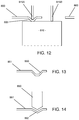
- FIG. 12 is a cross-section of a collector arm with current concentrator, as utilized in a resistance welding operation.
- FIG. 13 is a cross-sectional view of another current concentrator embodiment.
- FIG. 14 is a cross-sectional view of a current concentrator embodiment in which a current concentrator can be formed during the welding operation.
- FIG. 15 is a top plan view of a bridge collector plate having a module-level fusible link.
- FIG. 1 provides a schematic block diagram of such a battery pack.
- Battery pack 10 is formed from three battery modules 20 , namely, modules 20 A, 20 B and 20 C.
- Each module 20 includes a large quantity of battery cells 30 .
- Combining multiple modules into a battery pack can provided high levels of configurability, reusing common parts to meet a wide variety of pack specifications. Combining multiple modules may also provide for form factor flexibility. As described further herein, module-based battery pack constructions may also provide higher levels of safety and fault tolerance.
- FIG. 2 illustrates an exemplary battery module structure that may be utilized to implement high-power, easy-to-manufacture, space-efficient battery packs.
- battery module 100 includes battery retention frame 110 .
- Battery retention frame 110 serves to, amongst other things, physically orient and retain a number of battery cells 120 relative to the battery module as a whole.
- battery cells 120 are cylindrical in shape, and oriented with their longitudinal axes parallel to one another and the cell ends occupying common planes.
- FIG. 2 is a top plan view in which cells 120 are exposed through removal of various collectors and other structures, with cylindrical battery cells 120 oriented vertically and parallel to one another. Cells 120 may be arranged in repeating groups having alternating orientations i.e. polarity.
- module 100 features cells 120 arranged in left grouping 130 and right grouping 132 .
- Left subgroups 130 A, 130 C, 130 E and 130 G feature fourteen cells arranged in two rows of seven, with upward-facing cathodes.
- Left subgroups 130 B, 130 D, and 130 F also feature fourteen cells arranged in two rows of seven, but are oriented with opposite polarity, i.e. with anodes facing upward towards a top side of the module.
- right grouping 132 features subgroupings 132 A, 132 C, 132 E and 132 G with upward-facing anodes, while subgroups 132 B, 132 D and 132 F are oriented with opposite polarity, i.e. upward-facing cathodes. It is contemplated and understood that in other embodiments, differing configurations (including differing cell group sizes and polarities) may be employed.
- FIG. 3 illustrates the battery module of FIG. 2 , with collector plates applied thereto.
- Collector plates may be utilized to interconnect the anodes of one battery subgroup, with the cathodes of a neighboring battery subgroup.
- collector plate 140 A interconnects the cathodes of battery subgroup 130 A, while also forming a battery module output terminal 300 .
- the anodes of battery subgroup 130 A are electrically connected with the cathodes of battery subgroup 1308 via a collector plate on the bottom side of module 100 (not shown).
- collector plate 140 B The anodes of battery subgroup 130 B are electrically connected with the cathodes of battery subgroup 130 C by collector plate 140 B.
- collector plates 140 C, 140 D, 140 E, 140 F and 140 G serve to electrically connect the anodes of one battery cell subgroup with the cathodes of a neighboring battery cell subgroup.
- collector plates 140 A and 140 H connect with module-level negative and positive output terminals 300 and 302 , respectively.
- the bottom side of module 100 is illustrated the bottom plan view of FIG. 4 .
- the bottom side is generally analogous to the top side, with each cell's opposite polarity terminal exposed thereon and connected with a collector plate.
- the bottom side further includes a bridge collector plate 1401 , spanning left-side cell group 130 (specifically, subgroup 130 G) and right-side cell group 132 (specifically, subgroup 132 A).
- the bridge collector plate 1401 provides, amongst other things, module-level safety features, as described further below.
- FIG. 5 provides a perspective view of module 100 .
- Collector plates 140 may be arranged in various combinations to achieve desired levels of voltage and current capacity for each module size, as described in Applicant's U.S. Patent Application No. 62/675,495, filed on May 23, 2018, the contents of which are hereby incorporated by reference.
- use of collector plate construction may provide a highly compact battery module form factor.
- the plates are relatively thin, thereby adding very little thickness.
- the overall height of module 100 may be little more than the height of each cell 120 .
- collector plate constructions such as that of FIGS. 3-4 may present numerous advantages, one challenge in a collector plate battery module construction is material selection, balancing module performance and manufacturability.
- the collector plate In a high-power battery module application, preferably the collector plate will be constructed from an ultra-low resistance material having a relatively low cost.
- the collector plates must also form a reliable electrical interconnect with each cell, and preferably also avoid adding excess weight to the module.
- Resistance welding involves localized placement of ultra-low resistance electrodes to apply high levels of electric current through a junction to be welded. The applied energy operates to fuse the target components.
- One advantage of resistance welding for connecting battery cells with a collector plate is that the process is closed loop. Because the welding current flows directly through the components being welded, the amount of energy applied to the weld can be measured directly, so long as the path of welding current is controlled. In the event of a mis-weld, the welding apparatus can observe unexpected variation in weld energy towards identifying defects immediately during manufacture. Thus, resistance welding can offer an economical, highly reliable technique for battery module collector connections.
- FIGS. 6 and 7 illustrate an exemplary physical arrangement for welding a collector plate to a battery cell.
- FIG. 6 is a partial cutaway top plan view of a collector plate 510 overlying a battery cell electrode 500 .
- Collector plate 510 features a cell aperture 515 under which cell 500 is positioned.
- a Y-shaped collector fork 505 extends from collector plate 510 , over cell electrode 500 , and is electrically connected to cell electrode 500 .
- FIG. 7 provides a cross sectional slice view along cross-section A-A in FIG. 6 .
- welding electrodes 530 A and 530 B are placed in contact with opposite prongs of collector fork 505 , e.g. at positions 532 A and 532 B, respectively.
- Current typically passes between the electrodes, through the collector plate and cell, along a path of least resistance.
- Common cells include anodes and cathodes formed from steel.
- collector plate 510 and Y fork 505 are formed from a material such as nickel.
- a well-defined path of least resistance for the welding current may extend generally along path 525 ; i.e., current flows from welding electrode 530 A, into Y fork 505 at location 532 A, directly across the steel cell electrode 500 , into Y fork 505 at location 532 B, and into welding electrode 530 B. As the welding current passes between Y-fork 505 and cell electrode 500 , the two components are fused together.
- nickel collector plate may be satisfactory in some applications, in other applications it presents disadvantages.
- electric vehicle applications often seek to optimize for low cost, small battery module size and weight, high power output capabilities and high efficiency.
- the battery module Due to the large number of cells, preferably capable of high discharge rates, the battery module may generate a very high amount of current at peak draw.
- nickel's resistivity may limit a battery module's peak output and efficiency. Compensating for nickel's resistivity may require greater collector material volume, therefore increasing battery module size and weight.
- a battery module collector structure formed from a material having very low resistivity, given other design constraints. While the ultra-low resistivity of copper may be desirable for a collector structure material, traditional resistance welding techniques perform poorly when applied to copper collector structures. Current applied to a copper component by a copper electrode may be poorly controlled, resulting in greater incidence of failed welds. For example, in an embodiment of FIGS. 6 and 7 having a copper collector plate, welding current may pass between the welding electrodes by traveling around the length of Y-fork 505 (e.g. along path 520 ), rather than taking a physically-shorter path through the comparatively highly resistive steel cell electrode 500 .
- some welding current may pass into cell electrode 500 but at an undesirable or inconsistent location, rather than passing directly through Y-fork 505 .
- use of resistance welding to fuse a copper collector plate with a steel cell electrode may provide unreliable results.
- FIG. 8 is a top plan view of a collector plate 700 having current concentrator structures integrated therein.
- Collector plate 700 is formed primarily from copper to achieve low resistance, preferably with a coating for corrosion resistance such as tin-plating.
- collector plate 700 utilizes two different collector structures, for reasons described further herein below.
- a first collector structure 710 is used proximate cell anodes, and second collector structure 720 is used proximate cell cathodes.
- Anode collector structure 710 is illustrated in partial cutaway view in FIG. 9 ; analogous current concentrator structures may also be used in the cathode structure 720 .
- Collector structure 710 combines a current concentrator structure to promote effective resistance welding, with an integrated per-cell fusible link.
- Collector structure 710 includes a central aperture 711 under which a cell is positioned, with the cell length extending perpendicularly from the collector plate.
- Collector arm 712 extends around the periphery of aperture 711 to a central attachment point, which contacts with a battery cell electrode underlying the collector plate.
- Collector arm 712 acts as a fusible link.
- the arm length and cross-sectional area of collector arm 712 may be specified to provide a desired maximum energy carrying capacity. In the embodiment of FIG.
- collector arm 712 wraps around a periphery of aperture 711 in order to form a desired conductive path length before energy is dissipated into the bulk material of collector plate 700 .
- collector arm 712 includes a fuse portion 713 that is narrowed relative to the remainder of conductor arm 712 to define a locally minimized current carrying capacity, thereby provided a controlled location for fusing of the conductive path in the event that an underlying battery cell discharges at too high of a rate, such as a cell short.
- a current concentrator structure 714 is formed in the collector arm.
- FIG. 10 is a partial cutaway view of another collector structure embodiment, utilized for cell cathodes in the collector plate of FIG. 8 .
- Collector structure 720 includes a broader collector arm 722 extending into aperture 721 , and having current concentrator 724 .
- anode conductor arm 713 provides per-cell fuse protection integrated directly into the collector plate structures, while cathode structure 720 provides greater amounts of copper material connecting conductor plate 700 with underlying cells, thereby improving, e.g., heat dissipation from the cells.
- FIG. 11 is a cross-sectional view of the collector structure 720 with current concentrator structure 724 , along section line B-B.
- current concentrator 724 is formed from a rounded dimple, extending downwards from a flat plane in which the bulk of collector plate 700 primarily lies, towards an electrode surface of an underlying battery cell.
- the dimple may have an inner radius of approximately 0.75 mm, extending (with material thickness) to a point approximately 0.8 mm below a plane formed by collector plate 700 .
- Current concentrator 714 may be constructed similarly.
- FIG. 12 is a schematic illustration of a resistance welding operation, fusing a collector plate 800 having current concentrator structure 805 , to battery cell electrode 810 .
- a first welding electrode 815 A contacts a top surface of collector plate 800 proximate current concentrator 805 .
- a second welding electrode 815 B contacts battery cell electrode 810 directly.
- the welding current passes from first welding electrode 815 A, through current concentrator 805 into cell electrode 810 , then out through second welding electrode 815 B.
- This arrangement provides numerous advantages that operate in concert to facilitate consistent and reliable welding of the collector plate to the cell, even given the low resistivity of a copper collector plate and the resistance imbalance between the collector plate and battery electrode. For example, placing one welding electrode 815 A on the collector plate and the other welding electrode 8158 directly on battery electrode 810 (i.e. asymmetric welding electrode placement) forces the welding current to pass between collector plate 800 and battery electrode 810 , despite the low resistivity of collector plate 800 relative to battery electrode 810 . Meanwhile, current concentrator structure 805 promotes consistency in the location at which current passes between collector plate 800 and battery electrode 810 , concentrating that current into a defined location for a reliable and precisely-located weld, and preventing stray currents from running through the very low resistivity copper collector plate.
- conductor arm shapes such as that of FIG. 9 may be particularly beneficial to the above-described asymmetric welding process.
- wrapping collector arm 713 generally around the circumference or periphery of aperture 711 may provide multiple simultaneous benefits.
- One such benefit is providing sufficient collector arm length to form a structure that is reliably fusible, and doesn't merely act to pump heat into the cell and collector plate.
- the fusible link structure of FIG. 9 also provides a placement of current concentrator 714 (and therefore the collector plate welding point) within a relatively central portion of an underlying battery electrode.
- the illustrated fusible link structure tends to maximize the open space provided by aperture 711 over each cell, while minimizing the total amount of copper removed from the collector plate. Minimizing total copper removal promotes maximum total conductivity for the collector plate. Meanwhile, a generous size of aperture 711 provides generous clearance for a welding electrode to pass through aperture 711 and contact an underlying battery cell electrode during manufacture. A large aperture 711 also helps optimize the performance of heat sinks that may be applied on an end of each cell. For example, thermal paste may be applied directly to a cell through aperture 711 , enabling an overlying heat sink to conduct heat directly from the cell.
- FIGS. 8-12 illustrate current concentrator structures formed as rounded inward depressions or dimples in an otherwise flat collector plate
- FIG. 13 illustrates (in side cross-sectional view) an angular current concentrator 850 extending inward, towards the battery cell ends proximate thereto, from a plane in which the bulk of the associated collector plate 851 lies.
- FIG. 14 illustrates (in a schematic diagram cross-section at a point of contact between the welding electrode and collector plate) an embodiment in which current concentrator structures are formed in a collector plate integrally with the weld operation.
- a welding electrode 860 includes a pointed tip (shown, in the embodiment of FIG. 14 , being chisel-point or conical in cross-section, although other geometries could be utilized).
- a pointed tip of welding electrode 860 is applied to a top surface of collector plate 861 with sufficient force to deform collector plate 861 downwards at the point of contact with welding electrode 860 , forming current concentrator 862 .
- Such a welding process and mechanism may be utilized to form current concentrator structures during the welding operation, even with flat, inexpensively-manufactured collector plates.
- the fusible links to each cell may enhance battery pack safety, and minimize the impact of cell failure on the battery pack as a whole.
- high-power battery packs are also commonly implemented with pack-level fuses, to stop current flow in the event that a battery pack as a whole fails or otherwise exceeds maximum thermal or energy specifications.
- module-level fusing it may be desirable to implement module-level fusing. For example, in a battery pack featuring three modules connected in parallel, if one module were to enter thermal runaway or initiate an uncontrolled discharge, activating a fuse to disconnect the failed module may preserve the remaining modules, e.g.
- the pack as a whole may continue to function, potentially enabling its host machine to continue operation.
- One technique for fusing a battery module may involve attaching a fuse structure to a module output terminal.
- output terminals are typically exposed to mechanical stress and require connectors, potentially introducing added points of failure.
- Integrated module-level fusing may be effectively implemented via design of a bridge collector plate.
- a module-level fusible link may be particularly effective when formed in a bridge collector plate spanning two sides of the module.
- Such a bridge collector plate 1401 is shown in the embodiment of FIG. 4 .
- Bridge collector plate 1401 is shown in an enlarged partial cutaway view in FIG. 15 .
- Bridge collector plate 1401 includes a narrowed fusible link portion 1500 .
- module-level fusible link portion 1500 is formed in a portion of bridge collector plate 1401 that spans the left and right sides of the module, the entire module's current flows through it.
- Fusible link portion 1500 is sized to have a desired maximum current carrying capacity, determined by, e.g., the collector plate material specifications, and the geometry of portion 1500 .
- module-level fusible link 1500 will be sized to have a current carrying capacity that is less than the aggregate capacity of all of the module cell fusible links, but more than a pro rata allocation of the pack's fuse capacity.
Landscapes
- Chemical & Material Sciences (AREA)
- Chemical Kinetics & Catalysis (AREA)
- Electrochemistry (AREA)
- General Chemical & Material Sciences (AREA)
- Inorganic Chemistry (AREA)
- Connection Of Batteries Or Terminals (AREA)
Abstract
Description
Claims (2)
Priority Applications (1)
| Application Number | Priority Date | Filing Date | Title |
|---|---|---|---|
| US16/177,746 US11056752B2 (en) | 2017-11-01 | 2018-11-01 | Copper collector plate for high power battery modules |
Applications Claiming Priority (2)
| Application Number | Priority Date | Filing Date | Title |
|---|---|---|---|
| US201762580298P | 2017-11-01 | 2017-11-01 | |
| US16/177,746 US11056752B2 (en) | 2017-11-01 | 2018-11-01 | Copper collector plate for high power battery modules |
Publications (2)
| Publication Number | Publication Date |
|---|---|
| US20190131608A1 US20190131608A1 (en) | 2019-05-02 |
| US11056752B2 true US11056752B2 (en) | 2021-07-06 |
Family
ID=66244304
Family Applications (1)
| Application Number | Title | Priority Date | Filing Date |
|---|---|---|---|
| US16/177,746 Active 2038-12-26 US11056752B2 (en) | 2017-11-01 | 2018-11-01 | Copper collector plate for high power battery modules |
Country Status (1)
| Country | Link |
|---|---|
| US (1) | US11056752B2 (en) |
Families Citing this family (4)
| Publication number | Priority date | Publication date | Assignee | Title |
|---|---|---|---|---|
| US10573859B2 (en) * | 2018-07-03 | 2020-02-25 | Daniel Francis Roddy | Portable modular energy storage |
| CN110854322A (en) * | 2019-09-20 | 2020-02-28 | 杭州乾代科技有限公司 | Modularized lithium battery module |
| GB2623908B (en) * | 2022-03-18 | 2025-07-30 | The Structural Battery Company Ltd | A Structured Battery |
| GB2616842B (en) * | 2022-03-18 | 2024-05-08 | The Structural Battery Company Ltd | Battery and monocoque vehicle |
Citations (10)
| Publication number | Priority date | Publication date | Assignee | Title |
|---|---|---|---|---|
| US20100255355A1 (en) | 2006-09-25 | 2010-10-07 | Lg Chem, Ltd. | Connection-member for electrical connection of battery cells |
| US20150364744A1 (en) | 2013-01-29 | 2015-12-17 | Sanyo Electric Co., Ltd. | Electrode member and battery block |
| US20160073506A1 (en) * | 2014-09-10 | 2016-03-10 | Cellink Corporation | Interconnect for battery packs |
| US20160133908A1 (en) | 2014-11-10 | 2016-05-12 | Tyco Electronics Corporation | Bus bar for a battery connector system |
| US20160322623A1 (en) | 2015-04-29 | 2016-11-03 | Samsung Sdi Co., Ltd. | Battery module |
| US20160336575A1 (en) * | 2015-05-11 | 2016-11-17 | Gogoro Inc. | Electrical connector for portable multi-cell electrical energy storage device |
| US20160380319A1 (en) | 2015-06-25 | 2016-12-29 | Tyco Electronics Corporation | Battery module with a temperature monitoring assembly |
| US20170005378A1 (en) | 2015-06-30 | 2017-01-05 | Faraday&Future Inc. | Battery pack for vehicle energy-storage systems |
| US20170005371A1 (en) | 2015-06-30 | 2017-01-05 | Faraday&Future Inc. | Vehicle energy-storage systems |
| US20170062880A1 (en) | 2015-09-01 | 2017-03-02 | Duracell U.S. Operations, Inc. | Battery including an on-cell indicator |
-
2018
- 2018-11-01 US US16/177,746 patent/US11056752B2/en active Active
Patent Citations (10)
| Publication number | Priority date | Publication date | Assignee | Title |
|---|---|---|---|---|
| US20100255355A1 (en) | 2006-09-25 | 2010-10-07 | Lg Chem, Ltd. | Connection-member for electrical connection of battery cells |
| US20150364744A1 (en) | 2013-01-29 | 2015-12-17 | Sanyo Electric Co., Ltd. | Electrode member and battery block |
| US20160073506A1 (en) * | 2014-09-10 | 2016-03-10 | Cellink Corporation | Interconnect for battery packs |
| US20160133908A1 (en) | 2014-11-10 | 2016-05-12 | Tyco Electronics Corporation | Bus bar for a battery connector system |
| US20160322623A1 (en) | 2015-04-29 | 2016-11-03 | Samsung Sdi Co., Ltd. | Battery module |
| US20160336575A1 (en) * | 2015-05-11 | 2016-11-17 | Gogoro Inc. | Electrical connector for portable multi-cell electrical energy storage device |
| US20160380319A1 (en) | 2015-06-25 | 2016-12-29 | Tyco Electronics Corporation | Battery module with a temperature monitoring assembly |
| US20170005378A1 (en) | 2015-06-30 | 2017-01-05 | Faraday&Future Inc. | Battery pack for vehicle energy-storage systems |
| US20170005371A1 (en) | 2015-06-30 | 2017-01-05 | Faraday&Future Inc. | Vehicle energy-storage systems |
| US20170062880A1 (en) | 2015-09-01 | 2017-03-02 | Duracell U.S. Operations, Inc. | Battery including an on-cell indicator |
Also Published As
| Publication number | Publication date |
|---|---|
| US20190131608A1 (en) | 2019-05-02 |
Similar Documents
| Publication | Publication Date | Title |
|---|---|---|
| US11056752B2 (en) | Copper collector plate for high power battery modules | |
| KR102378374B1 (en) | Battery Module Having Bus-bar and Battery Pack | |
| US9887410B2 (en) | Flexible fusible link, systems, and methods | |
| US9184431B2 (en) | Modular battery system and components | |
| CN113764832B (en) | Busbar assembly and battery module with same | |
| CN113314803A (en) | Laminated bus bar for energy storage device | |
| JP2010092841A (en) | Power cell apparatus with three dimensional interconnect | |
| US10319494B2 (en) | Multi-functional busbar with interstitial passages | |
| US11302997B2 (en) | Automotive battery conductor plates with fusible links | |
| KR100542238B1 (en) | Battery module | |
| CN102244225B (en) | Battery pack and form the method for this battery pack | |
| CN114421095B (en) | Battery pole parallel electric connection structure, parallel battery row, battery pack and manufacturing method thereof | |
| US9023218B2 (en) | Method of making fusible links | |
| WO2013080136A1 (en) | A battery module | |
| US9899658B2 (en) | High current battery pack fusing system | |
| US9997763B2 (en) | High current battery pack fusing system | |
| WO2013131551A1 (en) | Electrically symmetrical battery cell connector | |
| KR20220151555A (en) | Laminated busbar for energy storage device | |
| WO2021123712A1 (en) | Battery module and battery pack | |
| EP3471168B1 (en) | Battery module | |
| US12381291B2 (en) | Collector-plate and wire-bond interconnections for battery module | |
| JP7297037B2 (en) | Secondary battery module | |
| KR102130827B1 (en) | Battery Pack | |
| KR20250126711A (en) | Simple and modular assembly of battery cells using printed circuit boards |
Legal Events
| Date | Code | Title | Description |
|---|---|---|---|
| AS | Assignment |
Owner name: LITHOS ENERGY, INC., CALIFORNIA Free format text: ASSIGNMENT OF ASSIGNORS INTEREST;ASSIGNORS:STAFL, ERIK;MEREDITH, JAMES;FERGUSON, KATELYN;REEL/FRAME:047383/0833 Effective date: 20181031 |
|
| FEPP | Fee payment procedure |
Free format text: ENTITY STATUS SET TO UNDISCOUNTED (ORIGINAL EVENT CODE: BIG.); ENTITY STATUS OF PATENT OWNER: SMALL ENTITY |
|
| FEPP | Fee payment procedure |
Free format text: ENTITY STATUS SET TO SMALL (ORIGINAL EVENT CODE: SMAL); ENTITY STATUS OF PATENT OWNER: SMALL ENTITY |
|
| STPP | Information on status: patent application and granting procedure in general |
Free format text: DOCKETED NEW CASE - READY FOR EXAMINATION |
|
| STPP | Information on status: patent application and granting procedure in general |
Free format text: NON FINAL ACTION MAILED |
|
| STPP | Information on status: patent application and granting procedure in general |
Free format text: NON FINAL ACTION MAILED |
|
| STPP | Information on status: patent application and granting procedure in general |
Free format text: RESPONSE TO NON-FINAL OFFICE ACTION ENTERED AND FORWARDED TO EXAMINER |
|
| STPP | Information on status: patent application and granting procedure in general |
Free format text: NOTICE OF ALLOWANCE MAILED -- APPLICATION RECEIVED IN OFFICE OF PUBLICATIONS |
|
| STPP | Information on status: patent application and granting procedure in general |
Free format text: PUBLICATIONS -- ISSUE FEE PAYMENT RECEIVED |
|
| STPP | Information on status: patent application and granting procedure in general |
Free format text: PUBLICATIONS -- ISSUE FEE PAYMENT VERIFIED |
|
| STCF | Information on status: patent grant |
Free format text: PATENTED CASE |
|
| MAFP | Maintenance fee payment |
Free format text: PAYMENT OF MAINTENANCE FEE, 4TH YR, SMALL ENTITY (ORIGINAL EVENT CODE: M2551); ENTITY STATUS OF PATENT OWNER: SMALL ENTITY Year of fee payment: 4 |