US11055977B2 - Expanding security tag - Google Patents
Expanding security tag Download PDFInfo
- Publication number
- US11055977B2 US11055977B2 US16/806,739 US202016806739A US11055977B2 US 11055977 B2 US11055977 B2 US 11055977B2 US 202016806739 A US202016806739 A US 202016806739A US 11055977 B2 US11055977 B2 US 11055977B2
- Authority
- US
- United States
- Prior art keywords
- tag
- security device
- dimension
- retracted
- response
- Prior art date
- Legal status (The legal status is an assumption and is not a legal conclusion. Google has not performed a legal analysis and makes no representation as to the accuracy of the status listed.)
- Active
Links
Images


Classifications
-
- G—PHYSICS
- G08—SIGNALLING
- G08B—SIGNALLING SYSTEMS, e.g. PERSONAL CALLING SYSTEMS; ORDER TELEGRAPHS; ALARM SYSTEMS
- G08B13/00—Burglar, theft or intruder alarms
- G08B13/22—Electrical actuation
- G08B13/24—Electrical actuation by interference with electromagnetic field distribution
- G08B13/2402—Electronic Article Surveillance [EAS], i.e. systems using tags for detecting removal of a tagged item from a secure area, e.g. tags for detecting shoplifting
- G08B13/2405—Electronic Article Surveillance [EAS], i.e. systems using tags for detecting removal of a tagged item from a secure area, e.g. tags for detecting shoplifting characterised by the tag technology used
- G08B13/2414—Electronic Article Surveillance [EAS], i.e. systems using tags for detecting removal of a tagged item from a secure area, e.g. tags for detecting shoplifting characterised by the tag technology used using inductive tags
- G08B13/2417—Electronic Article Surveillance [EAS], i.e. systems using tags for detecting removal of a tagged item from a secure area, e.g. tags for detecting shoplifting characterised by the tag technology used using inductive tags having a radio frequency identification chip
-
- E—FIXED CONSTRUCTIONS
- E05—LOCKS; KEYS; WINDOW OR DOOR FITTINGS; SAFES
- E05B—LOCKS; ACCESSORIES THEREFOR; HANDCUFFS
- E05B73/00—Devices for locking portable objects against unauthorised removal; Miscellaneous locking devices
- E05B73/0017—Anti-theft devices, e.g. tags or monitors, fixed to articles, e.g. clothes, and to be removed at the check-out of shops
-
- G—PHYSICS
- G06—COMPUTING OR CALCULATING; COUNTING
- G06K—GRAPHICAL DATA READING; PRESENTATION OF DATA; RECORD CARRIERS; HANDLING RECORD CARRIERS
- G06K19/00—Record carriers for use with machines and with at least a part designed to carry digital markings
- G06K19/06—Record carriers for use with machines and with at least a part designed to carry digital markings characterised by the kind of the digital marking, e.g. shape, nature, code
- G06K19/067—Record carriers with conductive marks, printed circuits or semiconductor circuit elements, e.g. credit or identity cards also with resonating or responding marks without active components
- G06K19/07—Record carriers with conductive marks, printed circuits or semiconductor circuit elements, e.g. credit or identity cards also with resonating or responding marks without active components with integrated circuit chips
- G06K19/077—Constructional details, e.g. mounting of circuits in the carrier
- G06K19/07749—Constructional details, e.g. mounting of circuits in the carrier the record carrier being capable of non-contact communication, e.g. constructional details of the antenna of a non-contact smart card
-
- G—PHYSICS
- G08—SIGNALLING
- G08B—SIGNALLING SYSTEMS, e.g. PERSONAL CALLING SYSTEMS; ORDER TELEGRAPHS; ALARM SYSTEMS
- G08B13/00—Burglar, theft or intruder alarms
- G08B13/22—Electrical actuation
- G08B13/24—Electrical actuation by interference with electromagnetic field distribution
- G08B13/2402—Electronic Article Surveillance [EAS], i.e. systems using tags for detecting removal of a tagged item from a secure area, e.g. tags for detecting shoplifting
- G08B13/2428—Tag details
- G08B13/2434—Tag housing and attachment details
-
- E—FIXED CONSTRUCTIONS
- E05—LOCKS; KEYS; WINDOW OR DOOR FITTINGS; SAFES
- E05B—LOCKS; ACCESSORIES THEREFOR; HANDCUFFS
- E05B73/00—Devices for locking portable objects against unauthorised removal; Miscellaneous locking devices
- E05B73/0017—Anti-theft devices, e.g. tags or monitors, fixed to articles, e.g. clothes, and to be removed at the check-out of shops
- E05B73/0047—Unlocking tools; Decouplers
Definitions
- the present disclosure relates generally to a security device configured to be secured to an article; more particularly to a security device that is configured to expand if tampered with.
- An Electronic Article Surveillance (EAS) system is designed to prevent unauthorized removal of an item from a controlled area.
- a typical EAS system may comprise a monitoring system and one or more security tags.
- the monitoring system may create a surveillance zone at an access point for the controlled area.
- a security tag may be fastened to the monitored item, such as an article of clothing. If the monitored item enters the surveillance zone, an alarm may be triggered indicating unauthorized removal.
- the security tag may be fastened to a number of different items. It may be desirable for a system to allow authorized release of the security tag, while making unauthorized release relatively difficult. Consequently, there may be a need for improved techniques in security tags in general.
- a security device configured to be secured to an article.
- the security device includes a tag, which may hereinafter interchangeably be referred to as a first expanding security device, having an expandable portion with a retracted dimension and an expanded dimension, wherein applying a first removal force to the tag in an attempt to remove the security device from the article releases the expandable portion causing a dimension of the tag to increase from the retracted dimension to the expanded dimension.
- a security device configured to be secured to an article
- the security device includes a first tag having an expandable portion with a retracted dimension and an expanded dimension.
- the security device further includes a second tag, which may hereinafter be interchangeably referred to as a second expandable security device or second security device, that is removably connectable to the first tag, wherein applying a first removal force to the first tag in an attempt to separate the first tag from the second tag releases the expandable portion causing a dimension of the first tag to increase from the retracted dimension to the expanded dimension.
- a security device configured to be secured to an article
- the security device includes a first tag having an expandable portion with a retracted dimension and an expanded dimension and a second tag that is removably connectable to the first tag. Applying a first removal force to the first tag or second tag in an attempt to separate the first tag from the second tag releases a biasing force causing configured to bias the expandable portion and causing a dimension of the first tag to increase from the retracted dimension to the expanded dimension.
- FIG. 1A is an example EAS tag that is useful for understanding the current disclosure
- FIG. 1B is a cross-sectional view of the EAS tag in FIG. 1 , taken along line A-A;
- FIG. 2 is a perspective view of an example of a first security device and second security device separated in accordance with one aspect of the disclosure
- FIG. 3 is a perspective view of an example of the first security device and second security device of FIG. 2 in a connected state in accordance with one aspect of the disclosure;
- FIG. 4 is a perspective view of an example of the first security device and second security device of FIGS. 2-3 in a connected state in and with the first security device in an expanded state in accordance with one aspect of the disclosure;
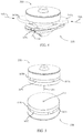
- FIG. 5 is a perspective view of an example of the first security device and second security in a separated state in accordance with one aspect of the disclosure
- FIG. 6 is a perspective view of an example of the first security device and second security device of FIG. 5 in a separated state with each security device in an expanded state in accordance with one aspect of the disclosure;
- FIG. 7 is a cut-away view of the example security device in FIGS. 2-6 in accordance with one aspect of the disclosure.
- FIG. 8 is a top exploded view of the example security device in FIGS. 2-7 in accordance with one aspect of the disclosure.
- FIG. 9 is a bottom exploded view of the example first security device in FIGS. 2-8 in accordance with one aspect of the disclosure.
- FIG. 10 is a top perspective partially assembled view of the example security device in FIGS. 2-9 in accordance with one aspect of the disclosure.
- FIG. 11 is a top perspective partially assembled view of the example security device in FIGS. 2-10 in accordance with one aspect of the disclosure.
- the instant disclosure relates to a method and apparatus related to the connection of Electronic article surveillance systems (EAS) tags to articles that are to be secured.
- EAS systems are used for inventory control and to prevent theft and similar unauthorized removal of articles from a controlled area.
- a system transmitter and a system receiver are used to establish a surveillance zone which must be traversed by any articles being removed from a controlled area.
- An EAS security tag may be affixed to each article (such as, but not limited to, clothing) and may include an active or passive device configured to interact with a signal being transmitted by the system transmitter into the surveillance zone. This interaction causes a further signal to be established in the surveillance zone and the signal may be received by the system receiver. Accordingly, upon movement of a tagged article through the surveillance zone, a signal will be received by the system receiver, identifying the unauthorized presence of the tagged article in the zone.
- Certain types of EAS security tags have been designed to be reusable and, thus, include releasable attachment devices for affixing the tags to the articles. Such attachment devices are further designed to be releasable by authorized personnel only so that unauthorized removal of a tag from a corresponding article is avoided. To this end, many attachment devices are made releasable only through the use of an associated special tool or detaching mechanism.
- Attachment devices for EAS security tags include a wide variety of different latching mechanisms designed to prevent unauthorized personnel from removing the pin from the tag.
- the stimulus needed to unlatch an EAS security tag depends upon the particular latching mechanism in use. Accordingly, a variety of different detaching units utilize various means to separate reusable, removable EAS security tags from articles of merchandise.
- Systems for unlatching EAS security tags include devices which may involve the application of a force to certain latching components of the EAS security tag. The force can be applied directly to latching components via a mechanical element (e.g. a probe or hook inserted into the tag) unlatching the tag and/or indirectly via magnet, for example. Regardless of how the force is applied, the result is a disengagement of a latching element that was previously engaged with an attachment pin in the tag, thereby allowing the tag to be removed from the article.
- a mechanical element e.g. a probe or hook inserted into the tag
- FIGS. 1A and 1B include one example of an EAS security tag 1 .
- the present aspects are not limited to use with an EAS security tag 1 as shown, but a brief description of such an exemplary tag is useful for understanding the inventive arrangements.
- the tag 1 includes an upper housing 2 and a lower housing 3 which are joined along corresponding side walls to form a closed tag body 1 A.
- the tag 1 further includes a tack assembly 4 having an enlarged tack head 4 A, an elongated tack body 4 B, and a pointed forward end 4 D (see, FIGS. 1, and 2 ).
- the tack assembly 4 is used to attach the tag body 1 A to an article 51 which is to be protected by the EAS tag 1 .
- an EAS sensor 5 which generates detectable signals.
- the EAS sensor 5 can be an acoustically resonant magnetic sensor.
- a wide variety of EAS sensors are known in the art and therefore such sensors will not be described here in detail.
- any suitable EAS sensor can be provided in the EAS security tag 1 .
- the article 51 is joined to the tag body 1 A by the tack assembly 4 by inserting the tack body 4 B into an opening in the wall of the upper housing 2 .
- the pointed end of the tack is received in an upstanding cavity or collar extending from an inner surface of the lower housing.
- the tack head 4 A seats in a recessed area in the upper housing.
- the article 51 is thus held between the tack head 4 A and the housing.
- a locking element 6 is provided within the tag body for releasably preventing the tack body 4 B from being withdrawn from the tag body.
- the tack assembly 4 and the article 51 thus become releasably locked to the EAS tag 1 .
- a hook 8 may be needed to reach and release the locking mechanism inside the security tag and, thus, detach the tack assembly 4 and the article from the tag body 1 A.
- the tag body 1 A is configured so that access to the internal locking mechanism is through an arcuate channel accessible through a curved slot 9 defined by one or more inner walls of the tag body 1 A.
- the hook 8 is introduced into the curved slot 9 of the tag body 1 A via rotation of the hook about its rearward end 8 B. The rotation is indicated by arrow 11 in FIG. 1A . This action causes the hook to be inserted within the tag until the forward end 8 A of the hook reaches and passes into the inner end of the channel to effect the unlocking operation.
- a magnet or electromagnet within a detacher device may impart a magnetic force on a ferromagnetic element within a tag body causing the tag to release the tack from the tag body.
- EAS tags that are usable with the current disclosure include but are not limited to: SuperTag Ink®, SuperTag®, SuperTag II®, and/or SuperTag III®, all manufactured by Sensormatic of Baca Raton Fla.
- an increased surface area may be desirable to provide an increased surface area to the security device connected to the article.
- increasing the size and/or surface area of the EAS security tag 1 and/or tack assembly 4 in FIGS. 1A and 1B may prevent unauthorized removal of the device and additionally may prevent an article from being usable and/or repairable if an attempt is made to cut or otherwise forcefully remove the security device from the article.
- an increase in size and/or surface area of the security device has the disadvantage of potentially causing a distraction to a potential customers or may be in the way when a customer tries an article on, to name a few example disadvantages.
- articles with security devices that give a visual indication that the security device has been tampered with store employees may be able to observe patterns such as specific articles and/or styles or types of articles that may be subject to theft, for example.
- a security device which may for example include an expandable security device, which may hereafter be interchangeably referred to as a first security device, in accordance with one aspect of the disclosure will be described with reference to FIGS. 2-4 .
- the example security device may include an expandable security device 200 and a second security device (e.g., an EAS tag 1 as described with reference to FIGS. 1A and 1B ).
- a second security device e.g., an EAS tag 1 as described with reference to FIGS. 1A and 1B
- an expandable security device 200 may replace tack assembly 4 in FIGS. 1A and 1B , for example.
- the expandable security device 200 may for example include a tack body 201 that is configured to be received by a receiving portion 110 of the second security device 100 .
- the expandable security device 200 may be detachably connectable to the second security device 100 in a similar fashion as described with reference to FIGS. 1A and 1B above.
- the expandable security device 200 connects to the second security device and is not removable unless separation of the expanding security device 200 and second security device 100 is effected by a specific detacher device (e.g., a detacher device with a hook 8 as described with relation to FIG. 1A above).
- a specific detacher device e.g., a detacher device with a hook 8 as described with relation to FIG. 1A above.
- the expandable security device 200 may include a plurality of expanding portions 207 A, 207 B, 207 C, and 207 D ( 207 D is hidden from view in FIGS. 2-4 ).
- the expanding portions 207 A-D may be configured to expand (e.g., as shown in FIG. 4 ) if a force is applied in either of directions 52 ( FIG. 3 ), for example, in an attempt to remove the expanding security device 200 and the second security device 100 from an article, expanding portions 207 A-D are configured to expand as shown in FIG. 4 , thus making unauthorized removal of the expandable security device 200 and/or first security device from an article more difficult.
- the expanding portions may for example be formed of a material having a bright or contrasting color (e.g., red, yellow, or orange) to further provide such a visual indication.
- the plurality of expanding portions may include any number, and is not limited to the example of 4 expanding portions described herein.
- the expanding portions 207 A-D of the security device may remain open or biased in an open direction until a resetting device is placed in contact or near the expanding security device 200 , and at least one of and/or all of the expanding portions 207 A-D are pressed inward (e.g., in directions 54 A-C) in order to “reset” the expanding security device 200 so that that the expanding portions 207 A-D remain in the retracted or non-expanded position (e.g., as shown in FIGS. 2 and 3 ).
- the expanding portions 207 A-D may remain open or biased in an expanded position until the expanding security 200 is removed from the second security device 100 via a specific detacher device (e.g., a detacher device with a hook 8 as described with relation to FIG. 1A above), at which point any one of and/or all of the expanding portions 207 A-D may be pressed inward (e.g., in directions 54 A-C) in order to “reset” the expanding security device 200 so that that the expanding portions 207 A-D remain in the retracted or non-expanded position (e.g., as shown in FIGS. 2 and 3 ).
- a specific detacher device e.g., a detacher device with a hook 8 as described with relation to FIG. 1A above
- any one of and/or all of the expanding portions 207 A-D may be pressed inward (e.g., in directions 54 A-C) in order to “reset” the expanding security device 200 so that that the expanding portions
- FIGS. 5 and 6 include another example implementation of the current disclosure.
- the security device may include the aforementioned expanding security device 200 , which may hereinafter be interchangeably referred to as a first expanding security device, and a second expanding security device 101 .
- the second expanding security device 101 may include a receiving portion 111 for receiving the tack body 201 of the first expanding security device 200 .
- Either one of or both of the first expanding security device 200 or the second expanding security device may further include therein an EAS sensor similar to EAS sensor 5 described with relation to FIG. 1B .
- the second expanding security device 101 may include a locking element (e.g., similar to locking element 6 in FIG. 1B ) and may lock and release in a similar fashion as described above with relation to FIGS. 1A and 1B .
- the second expanding security device may include second expanding portions 107 A, 107 B, 107 C, and 107 D that are configured to expand if an attempt is made to separate the second expanding security device 101 from the first expanding security device 200 .
- the second expanding portions 107 A-D of the second expanding security device 101 may function in a similar fashion as expanding portions 207 A-D described above. Once the expanding portions 107 A-D of the second expanding portion and/or the expanding portions 207 A-D are in the expanded position, the expanding portions 107 A-D and/or 207 A-D may remain open or biased in an open direction until a resetting device is placed in contact or near the second expanding security device 101 or the expanding security device 200 .
- At least one of and/or all of the expanding portions 107 A-D and/or 207 A-D may be pressed inward (e.g., in directions 54 A-C) in order to “reset” the expanding security device 200 so that that the expanding portions 207 A-D remain in the retracted or non-expanded position (e.g., as shown in FIG. 5 ).
- the expanding portions 207 A-D and/or second expanding portions 107 A-D may remain open or biased in an expanded position until the expanding security device 200 is removed from the second expanding security device 101 via a specific detacher device (e.g., a detacher device with a hook 8 as described with relation to FIG. 1A above).
- a specific detacher device e.g., a detacher device with a hook 8 as described with relation to FIG. 1A above.
- any one of and/or all of the expanding portions 207 A-D and/or second expanding portions 107 A-D may be pressed inward (e.g., in directions 54 A-C) in order to “reset” the devices so that that the expanding portions 207 A-D and/or second expanding portions 107 A-D remain in the retracted or non-expanded position (e.g., as shown in FIGS. 2 and 3 ).
- FIG. 7 includes an example cross-sectional view and FIGS. 8 and 9 include example top and bottom exploded views of one example of an expandable security device 200 .
- the expandable security device may include a cap 203 with a biasing member receiving portion 204 .
- the biasing member receiving portion 204 may be configured to receive a biasing member 208 , which may for example be a coil spring or elastic equivalent.
- the biasing member 208 e.g., coil spring
- the locking member 255 may include a cylindrical extension 256 ( FIG. 8 ) configured to receive the biasing member 208 thereon.
- the locking member 255 may be formed of a ferrous material that is capable of receiving a magnetic attractive force from a magnet or electromagnet, for example.
- the expandable security device 200 may further include a first rotating housing 214 .
- the rotatable housing 214 may include a locking member receiving portion or recessed portion 215 configured to selectively receive locking member 255 .
- the first rotating housing 214 may include a series of pivot posts 271 A-D for receiving and having rotatably connected thereto respective pivot post receiving portions 217 A-D of expanding portions 207 A-D.
- Each of the expanding portions 207 A-D may further include respective track followers 218 A-D.
- the track followers 218 A-D are configured to be slideably contained with respective tracks 278 A-D in a track housing 270 .
- expanding portions 207 A-D pivot about respective pivot posts 271 A-D of the rotatable housing 214 .
- respective track follower 218 A-D is guided within each of respective tracks 278 A-C of the track housing 270 .
- FIGS. 10 and 11 include examples of the expandable security device 200 with portions of the device removed in order to provide a clearer overview of one example of the expansion and retraction functionality of the expandable security device 200 .
- the rotatable housing 214 may be rotatably connected to the track housing 270 .
- the rotatable housing may be rotatable about axis 41 with respect to the track housing 270 .
- the rotatable housing may include an opening 220 ( FIGS. 9 and 10 ) and a recessed portion 215 surrounding the opening 220 .
- the track housing 270 may be configured to rotatably connect to the interface portion 211 ( FIGS. 7 and 8 ) of the track housing 270 via opening 220 ( FIGS.
- the upward movement in direction 3 T of the rotatable housing 314 relative to the track housing 270 causes the expanding portions 207 A-D to move from a retracted positon to an expanded position.
- One example of the aforementioned rotatable connection between the rotatable housing 214 and the track housing 270 includes snap fit portions 303 A and 303 B of interface portion 211 ( FIGS.
- the rotatable housing may include a series of stop tracks 305 A and 305 B configured to receive stop protrusions 210 A and 210 B, of the interface portion 211 ( FIGS. 7 and 9 ) of the track housing 270 .
- the interaction between the stop tracks 205 A and 205 B and the stop protrusions 210 A and 210 B may limit a relative rotation of the rotatable housing 214 and the track housing 270 .
- rotation of the rotatable housing 214 in direction 1 E causes the expanding portions 207 A-D to expand in directions 2 E due to the guiding of each respective track follower 218 A-D ( FIG. 9 ) within each of respective tracks 278 A-C ( FIG. 8 ) of the track housing 270 as described in further detail above.
- rotation of the rotatable housing 214 in direction 1 R causes the expanding portions 207 A-D to retract in directions 2 R.
- FIG. 11 includes one example of the expandable security device 200 with the cap 203 removed.
- the expandable security device may include a torsion spring 205 that is configured to provide a biasing force to the expanding portions 207 A-D by causing rotation of rotatable housing 214 with relation to the track housing 270 .
- rotation of the rotatable housing 214 with relation to the track housing causes the expansion or retraction of expanding portions 207 A-D via the interaction of each respective track follower 218 A-D ( FIG. 9 ) within each of respective tracks 278 A-C ( FIG.
- the torsion spring 205 may include a first end 220 received through a torsion spring receiving portion 221 of the rotatable housing 214 .
- a second end 219 of the torsion spring 205 may be received and held stationary by a second end receiving portion 218 (shown in FIGS. 7 and 9 ) of cap 203 .
- the aforementioned structure causes the torsion spring 205 to bias the expanding portions 207 A-D in direction 2 E.
- the locking member may include a series of retracted position receiving slots 320 A-B and a series of expanded position receiving slots 310 A-B. Both the retracted position receiving slots 320 A-B and the expanded position receiving slots 310 A-B are configured to captively receive respective stop protrusions 210 A-B of the track housing 270 .
- the aforementioned recessed portion 215 of the rotatable housing 214 may further include a set of posts 301 A and 301 B ( FIG. 10 —Hidden from view in FIG. 11 ) configured to be received by post receiving portions 302 A and 302 B (hidden from view in FIG. 11 ) of the locking member 155 .
- the expanding portions 207 A-D are locked in the expanded position (e.g., as in FIG. 11 ).
- the stop protrusions 210 A-B are engaged with the retracted position receiving slots 320 A-B, the expanding portions 207 A-D are locked in the retracted position (e.g., as shown in FIGS. 2, 3, and 5 ).
- the locking member 255 may be biased in a downward direction (e.g., direction 4 B) into the recessed portion 215 ( FIG. 10 ) of the rotatable housing 214 by biasing member 208 .
- the interaction between the post receiving portions 302 A-B of the locking member 155 and respective posts 301 A-B of the rotatable housing 214 allow the locking member 255 to move in an upward direction (e.g., direction 3 T), if a force that is greater than the biasing force of the biasing member 208 is imparted on the locking member 255 while preventing the locking member 255 from rotating with relation to the rotatable housing 214 .
- the locking member 255 may be formed of a ferrous material and an attractive magnetic force may be applied to the locking member 255 by a magnetic resetting and/or detaching device to cause the locking member 255 to move in an upward direction (e.g., direction 3 T).
- the attractive force applied by the magnet of the resetting and/or detaching device may be great enough to overcome the biasing force of biasing member 208 and thus cause the locking device to move in upward direction causing the locking member 255 to separate from the recessed portion 215 ( FIG.
- an upward movement in direction 3 T of the rotatable housing 314 relative to the track housing 270 that overcomes the downward biasing force provided by biasing member 108 on locking member 255 would also cause a disengagement between the stop protrusions 210 A-B and the retracted position receiving slots 320 A-B of the locking member 155 .
- the aforementioned structure causes the expandable security device 200 to expand if an attempt is made to remove the security device 200 from an article and allows the expandable security device to be “reset” via use of a detachment device.
- the expanding portions 207 A-D are in the retracted position (e.g., as in FIGS. 2, 3, 5, 7, and 9 )
- the locking member 255 is biased downward in direction 4 B.
- the engagement between the stop protrusions 210 A-B and the retracted position receiving slots 320 A-B prevents the rotatable housing from rotating with respect to the track housing 270 due to the force imparted by the torsion spring 205 .
- the force overcomes the biasing force provided by biasing member 108 causing a momentary separation and disengagement between the stop protrusions 210 A-D and the retracted position receiving slots 320 A-B causing the torsion spring 205 to effect a relative rotation between the rotatable housing 214 and the track housing 270 .
- the rotation of the rotatable housing due to the force applied by the torsion spring causes the expanding portions 207 A-D to move in directions 2 E to the expanded position as in FIG. 11 .
- the aforementioned rotation causes the stop protrusions 210 A-D to engage with the expanded position receiving slots 310 A-B as in FIG. 11 , thus locking the expanding portions 207 A-D in the expanded position.
- the expandable security device 200 device may be “reset” or allow for the expanding portions 207 A-D to be returned to the retracted position and locked in place.
- a magnetic detachment device is placed upon or in the vacuity of cap 203 ( FIGS. 7-9 ).
- the magnetic detachment device supplies a sufficient magnetic force in direction 3 T ( FIG. 11 ) to the ferrous locking member 255 to overcome the biasing force provided by biasing member 208 causing a separation and disengagement between the stop protrusions 210 A-D and the expanded position receiving slots 310 A-B.
- a user and/or the detachment device may apply an inward force (e.g., inward directions 54 A-D in FIG.
- the device may be “reset” with the expandable portions 207 A-D in the retracted position.
- any one of or a combination of the aforementioned features may be usable within an EAS tag or security device.
- the aforementioned examples are not intended to be limiting.
- a magnetic removal device and ferrous locking member 255 are given as examples, a mechanical device may directly contact the locking member 255 perform the same functions, to name one example.
- a method of disconnecting examples of the first security device or first expandable security device from the second security device or second expandable security device using a hook 8 is given, the first security device or first expandable security device may be disconnected from the second security device or second expandable security device via the application of a magnetic force, to name another example.
Landscapes
- Physics & Mathematics (AREA)
- Engineering & Computer Science (AREA)
- General Physics & Mathematics (AREA)
- Automation & Control Theory (AREA)
- Computer Security & Cryptography (AREA)
- Electromagnetism (AREA)
- Computer Hardware Design (AREA)
- Microelectronics & Electronic Packaging (AREA)
- Theoretical Computer Science (AREA)
- Burglar Alarm Systems (AREA)
Abstract
Description
Claims (20)
Priority Applications (1)
| Application Number | Priority Date | Filing Date | Title |
|---|---|---|---|
| US16/806,739 US11055977B2 (en) | 2019-09-20 | 2020-03-02 | Expanding security tag |
Applications Claiming Priority (2)
| Application Number | Priority Date | Filing Date | Title |
|---|---|---|---|
| US201962903498P | 2019-09-20 | 2019-09-20 | |
| US16/806,739 US11055977B2 (en) | 2019-09-20 | 2020-03-02 | Expanding security tag |
Publications (2)
| Publication Number | Publication Date |
|---|---|
| US20210090414A1 US20210090414A1 (en) | 2021-03-25 |
| US11055977B2 true US11055977B2 (en) | 2021-07-06 |
Family
ID=74882005
Family Applications (1)
| Application Number | Title | Priority Date | Filing Date |
|---|---|---|---|
| US16/806,739 Active US11055977B2 (en) | 2019-09-20 | 2020-03-02 | Expanding security tag |
Country Status (1)
| Country | Link |
|---|---|
| US (1) | US11055977B2 (en) |
Cited By (1)
| Publication number | Priority date | Publication date | Assignee | Title |
|---|---|---|---|---|
| USD988164S1 (en) | 2018-03-02 | 2023-06-06 | Sensormatic Electronics, LLC | Security tag |
Families Citing this family (1)
| Publication number | Priority date | Publication date | Assignee | Title |
|---|---|---|---|---|
| US20220178177A1 (en) * | 2019-04-17 | 2022-06-09 | Linda FAIRWEATHER | Clothing Tag |
Citations (1)
| Publication number | Priority date | Publication date | Assignee | Title |
|---|---|---|---|---|
| US20140077954A1 (en) * | 2012-09-20 | 2014-03-20 | Tyco Fire & Security Gmbh | Security tag for application to footwear |
-
2020
- 2020-03-02 US US16/806,739 patent/US11055977B2/en active Active
Patent Citations (1)
| Publication number | Priority date | Publication date | Assignee | Title |
|---|---|---|---|---|
| US20140077954A1 (en) * | 2012-09-20 | 2014-03-20 | Tyco Fire & Security Gmbh | Security tag for application to footwear |
Cited By (5)
| Publication number | Priority date | Publication date | Assignee | Title |
|---|---|---|---|---|
| USD988164S1 (en) | 2018-03-02 | 2023-06-06 | Sensormatic Electronics, LLC | Security tag |
| USD988894S1 (en) * | 2018-03-02 | 2023-06-13 | Sensormatic Electronics, LLC | Security tag with retractable pin |
| USD988895S1 (en) * | 2018-03-02 | 2023-06-13 | Sensormatic Electronics, LLC | Security tag with retractable pin |
| USD997758S1 (en) * | 2018-03-02 | 2023-09-05 | Sensormatic Electronics, LLC | Security tag |
| USD1104813S1 (en) | 2018-03-02 | 2025-12-09 | Sensormatic Electronics, LLC | Security tag |
Also Published As
| Publication number | Publication date |
|---|---|
| US20210090414A1 (en) | 2021-03-25 |
Similar Documents
| Publication | Publication Date | Title |
|---|---|---|
| US8341985B2 (en) | Security device for ring products | |
| EP2404016B1 (en) | Security hard tag with attachment clip | |
| CA2839878C (en) | Security system tag magnetic clutch and method | |
| US6449991B1 (en) | One part theft deterrent device | |
| US8547228B2 (en) | Multi-attach reusable tag | |
| US8547229B2 (en) | Multi-attach disposable tag | |
| US20050091809A1 (en) | Electronic article surveillance (EAS) tag compatible with mechanical and magnetic unlocking detachers | |
| US20120043228A1 (en) | Security device for products on display packaging | |
| EP2919212B1 (en) | Integrated lock and pin security tag | |
| US20110018716A1 (en) | Two-stage universal security hard tag and method for attaching and detaching | |
| US11055977B2 (en) | Expanding security tag | |
| US11984004B2 (en) | Security tag for loss prevention | |
| US20120055944A1 (en) | Security system hard tag clamp and clamping method | |
| GB2305212A (en) | Security tag device | |
| US20250341120A1 (en) | Retail security assembly | |
| HK1198264B (en) | Security system tag magnetic clutch and method | |
| HK1181177A (en) | Magnetically releasable security tag |
Legal Events
| Date | Code | Title | Description |
|---|---|---|---|
| AS | Assignment |
Owner name: SENSORMATIC ELECTRONICS, LLC, DELAWARE Free format text: ASSIGNMENT OF ASSIGNORS INTEREST;ASSIGNOR:PEREZ, SERGIO M.;REEL/FRAME:051983/0430 Effective date: 20190920 |
|
| FEPP | Fee payment procedure |
Free format text: ENTITY STATUS SET TO UNDISCOUNTED (ORIGINAL EVENT CODE: BIG.); ENTITY STATUS OF PATENT OWNER: LARGE ENTITY |
|
| AS | Assignment |
Owner name: SENSORMATIC ELECTRONICS, LLC, FLORIDA Free format text: CORRECTIVE ASSIGNMENT TO CORRECT THE CORRECT STATE OF ASSIGNEE PREVIOUSLY RECORDED AT REEL: 051983 FRAME: 0430. ASSIGNOR(S) HEREBY CONFIRMS THE ASSIGNMENT;ASSIGNOR:PEREZ, SERGIO M.;REEL/FRAME:052676/0832 Effective date: 20190920 |
|
| STPP | Information on status: patent application and granting procedure in general |
Free format text: NOTICE OF ALLOWANCE MAILED -- APPLICATION RECEIVED IN OFFICE OF PUBLICATIONS |
|
| STPP | Information on status: patent application and granting procedure in general |
Free format text: PUBLICATIONS -- ISSUE FEE PAYMENT RECEIVED |
|
| STPP | Information on status: patent application and granting procedure in general |
Free format text: PUBLICATIONS -- ISSUE FEE PAYMENT VERIFIED |
|
| STCF | Information on status: patent grant |
Free format text: PATENTED CASE |
|
| MAFP | Maintenance fee payment |
Free format text: PAYMENT OF MAINTENANCE FEE, 4TH YEAR, LARGE ENTITY (ORIGINAL EVENT CODE: M1551); ENTITY STATUS OF PATENT OWNER: LARGE ENTITY Year of fee payment: 4 |