US11055260B2 - System and method for compression of geospatial location data - Google Patents
System and method for compression of geospatial location data Download PDFInfo
- Publication number
- US11055260B2 US11055260B2 US16/717,731 US201916717731A US11055260B2 US 11055260 B2 US11055260 B2 US 11055260B2 US 201916717731 A US201916717731 A US 201916717731A US 11055260 B2 US11055260 B2 US 11055260B2
- Authority
- US
- United States
- Prior art keywords
- geospatial location
- projection
- geospatial
- compressed
- location
- Prior art date
- Legal status (The legal status is an assumption and is not a legal conclusion. Google has not performed a legal analysis and makes no representation as to the accuracy of the status listed.)
- Expired - Fee Related, expires
Links
Images


Classifications
-
- G—PHYSICS
- G06—COMPUTING OR CALCULATING; COUNTING
- G06F—ELECTRIC DIGITAL DATA PROCESSING
- G06F16/00—Information retrieval; Database structures therefor; File system structures therefor
- G06F16/10—File systems; File servers
- G06F16/17—Details of further file system functions
- G06F16/1727—Details of free space management performed by the file system
-
- G—PHYSICS
- G06—COMPUTING OR CALCULATING; COUNTING
- G06F—ELECTRIC DIGITAL DATA PROCESSING
- G06F16/00—Information retrieval; Database structures therefor; File system structures therefor
- G06F16/20—Information retrieval; Database structures therefor; File system structures therefor of structured data, e.g. relational data
- G06F16/29—Geographical information databases
-
- G—PHYSICS
- G06—COMPUTING OR CALCULATING; COUNTING
- G06F—ELECTRIC DIGITAL DATA PROCESSING
- G06F16/00—Information retrieval; Database structures therefor; File system structures therefor
- G06F16/30—Information retrieval; Database structures therefor; File system structures therefor of unstructured textual data
- G06F16/38—Retrieval characterised by using metadata, e.g. metadata not derived from the content or metadata generated manually
- G06F16/387—Retrieval characterised by using metadata, e.g. metadata not derived from the content or metadata generated manually using geographical or spatial information, e.g. location
-
- G—PHYSICS
- G06—COMPUTING OR CALCULATING; COUNTING
- G06F—ELECTRIC DIGITAL DATA PROCESSING
- G06F16/00—Information retrieval; Database structures therefor; File system structures therefor
- G06F16/90—Details of database functions independent of the retrieved data types
- G06F16/907—Retrieval characterised by using metadata, e.g. metadata not derived from the content or metadata generated manually
- G06F16/909—Retrieval characterised by using metadata, e.g. metadata not derived from the content or metadata generated manually using geographical or spatial information, e.g. location
-
- G—PHYSICS
- G06—COMPUTING OR CALCULATING; COUNTING
- G06T—IMAGE DATA PROCESSING OR GENERATION, IN GENERAL
- G06T17/00—Three dimensional [3D] modelling, e.g. data description of 3D objects
- G06T17/05—Geographic models
-
- H—ELECTRICITY
- H03—ELECTRONIC CIRCUITRY
- H03M—CODING; DECODING; CODE CONVERSION IN GENERAL
- H03M7/00—Conversion of a code where information is represented by a given sequence or number of digits to a code where the same, similar or subset of information is represented by a different sequence or number of digits
- H03M7/30—Compression; Expansion; Suppression of unnecessary data, e.g. redundancy reduction
- H03M7/3068—Precoding preceding compression, e.g. Burrows-Wheeler transformation
- H03M7/3071—Prediction
- H03M7/3075—Space
-
- H—ELECTRICITY
- H03—ELECTRONIC CIRCUITRY
- H03M—CODING; DECODING; CODE CONVERSION IN GENERAL
- H03M7/00—Conversion of a code where information is represented by a given sequence or number of digits to a code where the same, similar or subset of information is represented by a different sequence or number of digits
- H03M7/30—Compression; Expansion; Suppression of unnecessary data, e.g. redundancy reduction
- H03M7/40—Conversion to or from variable length codes, e.g. Shannon-Fano code, Huffman code, Morse code
- H03M7/4031—Fixed length to variable length coding
-
- H—ELECTRICITY
- H03—ELECTRONIC CIRCUITRY
- H03M—CODING; DECODING; CODE CONVERSION IN GENERAL
- H03M7/00—Conversion of a code where information is represented by a given sequence or number of digits to a code where the same, similar or subset of information is represented by a different sequence or number of digits
- H03M7/30—Compression; Expansion; Suppression of unnecessary data, e.g. redundancy reduction
- H03M7/70—Type of the data to be coded, other than image and sound
-
- H—ELECTRICITY
- H04—ELECTRIC COMMUNICATION TECHNIQUE
- H04L—TRANSMISSION OF DIGITAL INFORMATION, e.g. TELEGRAPHIC COMMUNICATION
- H04L67/00—Network arrangements or protocols for supporting network services or applications
- H04L67/50—Network services
- H04L67/56—Provisioning of proxy services
- H04L67/565—Conversion or adaptation of application format or content
- H04L67/5651—Reducing the amount or size of exchanged application data
Definitions
- This disclosure relates generally to the compression of data.
- this disclosure relates to the compression of geospatial location data.
- embodiments disclosed herein relate to the compression of geospatial location data in geospatial information systems, including embodiments that reduce storage or bandwidth requirements of such systems.
- Geospatial information systems are utilized for capturing, storing, analyzing or otherwise managing geographic data and associated attributes which are spatially referenced to the earth.
- This geospatial information can be gathered from multiple, disparate sources, and used to build a unified, coherent data store which is managed by a geospatial information provider.
- the geospatial information gathered in the data store can then be provided to various other entities that require geospatial information for their operation over a computer network.
- geospatial information may be utilized by delivery companies, online map services that provide map information and routing information to end users, among many others.
- geospatial information system may thus receive and process a large amount of geospatial event data, including geospatial location data.
- geospatial information systems may provide this geospatial event data (including this geospatial location data) over the computer network in response to a high volume of requests. Accordingly, when managing this geospatial location data (e.g., storing or transmitting such data) providers and users of geospatial information systems are often forced to make a difficult choice between utilizing more storage and network bandwidth, or of running a simplification process which would represent geospatial data less accurately.
- What is desired is the ability to represent geospatial locations in a manner that reduces the data and computing resources used to store or transmit such geospatial locations, or allows more geospatial locations to stored or transmitted under a given set of storage and bandwidth limitations.
- a prediction for that geospatial location may be determined.
- a prediction of a geospatial location may be any reference point that may be determined in order to compress or decompress the geospatial location.
- Such a prediction may therefore be a known reference location (e.g., including a static location), may be a prediction created by an algorithmic determination of a location (for example, based on a bounded geographical area or a previous geospatial location in a set of geospatial locations) or may be otherwise created.
- a geometrical projection of the Earth can then be created.
- a projection is a systematic transformation of the latitudes and longitudes of locations from the surface of a sphere or an ellipsoid into locations on a geometric shape.
- a cubic projection of the Earth may be utilized.
- the faces of the cubic projection can also be subdivided using a number of subdivisions per face to subdivide each face of the cubic projection to create a set of vertices on each face of the cubic projection.
- the number of subdivisions may be selected based on a desired precision or desired amount of compression (or balance therebetween) for the geospatial location, with a higher number of axes resulting in relatively greater accuracy (with relatively less compression) and a fewer number of axes resulting in relatively greater compression (with relatively less accuracy).
- the vertices created by the subdivisions can then be assigned identifiers.
- the number assigned to the nearest vertex to the geospatial location to be compressed can then be determined.
- the geospatial location to be compressed can be projected onto the cubic projection (e.g., on a corresponding face of the cubic projection).
- the vertex e.g., as defined by the subdivisions on the corresponding face of the cube
- the associated number of this nearest vertex can then be determined It is this vertex number that is the compressed geospatial location.
- substantially the reverse set of operations may be performed. Specifically, when a compressed geospatial location is received (e.g., as an integer value in a variable integer length format), a prediction of that geospatial location may be created.
- the method used in predicting the geospatial location when decompressing the received geospatial location may be equivalent to (the same as or substantially similar to) the method used to predict the geospatial location during compression. In this manner, the resulting prediction during decompression may be substantially equivalent to (or the same as or substantially similar to) the prediction obtained when the geospatial location was compressed.
- a geometrical projection of the Earth can then be created.
- the geometrical projection may be equivalent to (or the same as or substantially similar to) the geometrical projection used during compression of the geospatial location.
- a prediction and cubic projection with subdivisions and vertices with numerical assignments equivalent to those created during compression may have been created.
- the number of the vertex of the subdivided cubic projection equivalent to the integer value of the compressed geospatial location may then be determined and this vertex projected back to its corresponding location on Earth to determine the decompressed latitude and longitude value (e.g., the determined corresponding location on Earth).
- a geospatial location may thus be compressed (e.g., into a single integer) and stored or transmitted using, for example, a variable length integer format, a number of advantages and technical improvements may be realized.
- a location represented by a single numerical value as opposed to say, separate latitude and longitudes or a difference for each of latitude and longitude
- there is only overhead for one value e.g., one variable length integer
- the number of bits needed to store a geospatial location is correlated with the distance from that prediction.
- embodiments as disclosed herein may provide substantial technical advantages and improvements in computing systems, including the use of less storage space for storing these geospatial locations (e.g., fewer bytes) while maintaining high precision of such geospatial locations. Moreover, less bandwidth may be required to transmit one or more geospatial locations, reducing transmission times for such geospatial locations.
- FIG. 1A is a diagrammatic representation of an architecture including a geospatial information system including an embodiment of a location compressor.
- FIG. 1B is a depiction of an interface that may be utilized with embodiments of a geospatial information system.
- FIG. 2 is a flow diagram depicting one embodiment of a method for compressing a geospatial location.
- FIGS. 3A and 3B are diagrammatic representations of examples of cubic projections.
- FIG. 3C is a diagrammatic representation of an example of a cubic projection with subdivided faces.
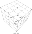
- FIG. 3D is a diagrammatic representation of an example of a cubic projection with subdivided faces and identifiers assigned to vertices.
- FIG. 3E is a diagrammatic representation of an example of a cubic projection with subdivided faces and an identifier assigned to a nearest vertex.
- FIG. 4 is a flow diagram depicting one embodiment of a method for decompressing a geospatial location.
- geospatial information system provider may compile geospatial information and maintain a geospatial information system.
- the geospatial information can be gathered from multiple, disparate sources, and used to build a unified, coherent data store which is managed by the geospatial information provider.
- the geospatial information gathered in the data store can then be provided to various other entities that require geospatial information for their operation over a computer network.
- geospatial information may be utilized by delivery companies, online map services that provide map information and routing information to end users, among many others.
- IoT Internet of Things
- traffic devices e.g., air traffic, road traffic, marine traffic, etc.
- seismographic data computing device, video cameras, devices monitoring building status, or a whole host of other devices or systems.
- a geospatial information system may receive hundreds of millions of geospatial data events (or more) from various information sources each day, where this geospatial event data may include geospatial location data. Moreover, that geospatial information system may provide this geospatial event data, including this geospatial location data in response to hundreds of thousands or millions of requests each day. As a result, millions or billions (or more) sets of geospatial location data may be stored and regularly updated at a geospatial information system, or provided over a computer network from the geospatial information system to entities that require such geospatial data.
- such geospatial location data is stored as tuples of latitude and longitude pairs in IEEE 754 double-precision binary floating point format.
- 128 bits may be required.
- the storage or transfer of geospatial location data according to this format in the environments described may result in significant burden on the storage and network bandwidth requirements.
- the greatest precision in representing locations in that coordinate system lies near the poles of the Earth.
- the vast majority of most geospatial location data obtained and provided by geospatial location systems is not located near the poles.
- the latitude and longitude coordinate system thus has a non-uniform distribution of precision, with the least precision being available in locations where the most precision is desired and, conversely, the most precision available where less precision may be needed.
- geospatial location system of latitude/longitude are utilized in the description of certain embodiments as disclosed, embodiments as used herein may be usefully applied to compress and decompress geospatial location represented in another manner.
- such a geospatial location to be compressed could be represented in Mercator projection, or another Geographic Coordinate System like 3D Cartesian coordinates, and such locations could be compressed and decompressed using embodiments as disclosed.
- providers and users of geospatial information systems are often forced to make a difficult choice between utilizing more storage and network bandwidth, or of running a simplification process which would represent geospatial data less accurately with fewer points.
- geospatial locations such that these geospatial locations can be represented (e.g., in a binary format) using less data (e.g., fewer bytes) and the computing resources to store or transmit such geospatial locations may be reduced, or more geospatial locations may be stored or transmitted under a given set of storage and bandwidth limitations.
- a prediction for that geospatial location may be determined.
- a prediction of a geospatial location may be any reference point that may be determined in order to compress or decompress the geospatial location.
- Such a prediction may therefore be a known reference location (e.g., including a static location), may be a prediction created by an algorithmic determination of a location (for example, based on a bounded geographical area or a previous geospatial location in a set of geospatial locations) or may be otherwise created.
- a geometrical projection of the Earth can then be created.
- a projection is a systematic transformation of the latitudes and longitudes of locations from the surface of a sphere or an ellipsoid into locations on a geometric shape.
- a cubic projection of the Earth may be utilized.
- One example of a cubic projection that may be utilized is a quadrilateralized spherical cube (QSC).
- QSC quadrilateralized spherical cube
- Such a projection is an equal-area projection that introduces only limited angular distortions and treats all cube sides equally (i.e., it does not use different projections for polar areas and equatorial areas).
- the cubic projection may thus be created such that the prediction is in one of the corners of the cubic projection.
- the faces of the cubic projection can also be subdivided using a number of subdivisions per face to subdivide each face of the cubic projection to create a set of vertices on each face of the cubic projection. These subdivisions may occur, for example along horizontal and vertical axes of the faces of the cubic projections.
- the number of subdivisions e.g., the number of horizontal or vertical axes selected for use
- the vertices created by the subdivisions can then be assigned identifiers.
- the vertex of the cubic projection corresponding to the prediction may be assigned a lowest numerical identifier (e.g., zero) and the other vertices may be assigned numerical identifiers in increasing order starting with the vertex or vertices closest to the vertex corresponding to the prediction (e.g., vertex zero).
- the vertices may be assigned increasing numerical identifiers according to a “ring order” defined by a spiral pattern beginning with the prediction vertex (e.g., vertex zero) and increasing in a clockwise or counter-clockwise pattern around the prediction vertex.
- the number assigned to the nearest vertex to the geospatial location to be compressed can then be determined.
- the geospatial location to be compressed can be projected onto the cubic projection (e.g., on a corresponding face of the cubic projection).
- the vertex (e.g., as defined by the subdivisions on the corresponding face of the cube) nearest to the projected geospatial location on the cube face, and the associated number of this nearest vertex can then be determined (e.g., using a Euclidean distance measure or the like). It is this vertex number that is the compressed geospatial location.
- This number may be stored or transmitted using, for example, a variable length integer format such as PrefixVarint, LEB128 or the like.
- substantially the reverse set of operations may be performed. Specifically, when a compressed geospatial location is received (e.g., as an integer value in a variable integer length format), a prediction of that geospatial location may be created.
- the method used in predicting the geospatial location when decompressing the received geospatial location may be equivalent to (or the same as) the method used to predict the geospatial location during compression. In this manner, the resulting prediction during decompression may be substantially equivalent to (or the same as or substantially similar to) the prediction obtained when the geospatial location was compressed.
- a geometrical projection of the Earth can then be created.
- the geometrical projection may be equivalent to (or the same as or substantially similar to) the geometrical projection used during compression of the geospatial location. Therefore, in one embodiment, a QSC projection may be created during decompression, where the prediction created during decompression is in one of the corners of the cubic projection.
- the faces of this cubic projection can also be subdivided and ordered using a number of subdivisions per face and an ordering scheme equivalent to (or the same as or substantially similar to) the number of subdivisions created during the compression of the geospatial location.
- a prediction and cubic projection with subdivisions and vertices with numerical assignments equivalent to (or the same as or substantially similar to) those created during compression may have been created.
- the number of the vertex of the subdivided cubic projection equivalent to the integer value of the compressed geospatial location may then be determined and this vertex projected back to its corresponding location on Earth to determine the decompressed latitude and longitude value (e.g., the determined corresponding location on Earth).
- a geospatial location may thus be compressed into a single integer and stored or transmitted using, for example, a variable length integer format, a number of advantages and technical improvements may be realized.
- a location represented by a single numerical value as opposed to say, separate latitude and longitudes or a difference for each of latitude and longitude
- there is only overhead for one value e.g., one variable length integer
- the number of bits needed to store a geospatial location is correlated with the distance from that prediction.
- embodiments as disclosed herein may provide substantial technical advantages and improvements in computing systems, including the use of less storage space for storing these geospatial locations (e.g., fewer bytes) while maintaining high precision of such geospatial locations. Moreover, less bandwidth may be required to transmit one or more geospatial locations, reducing transmission times for such geospatial locations.
- geospatial information system 120 may compile geospatial information including geospatial locations from multiple, disparate sources 110 over network 102 which may be the Internet, an intranet, a cellular network, another type of wireless or wired network or some combination of these types of networks.
- these information sources 110 may include data sources associated with weather monitors, traffic devices (e.g., air traffic, road traffic, marine traffic, etc.), devices for delivery fleets, devices related to lighting, parking, water flow for bodies of water or city utilities, seismographic data, computing devices, video cameras, devices monitoring building status, or a whole host of other entities, devices or systems.
- the geospatial information obtained from the geospatial data information sources 110 can be stored in data store 122 maintained by the geospatial information system 120 .
- the geospatial information in the data store 122 or associated data can then be provided to various other entities that require geospatial information for their operation over network 102 through, for example, a services or other type of interface 132 .
- a client application 152 that may be a thin client application, a thick client application, a web-based application or another type of application, may request or receive certain geospatial location data through the interface 132 of geospatial information system 120 .
- the geospatial information system 120 may obtain the requested geospatial location data and return it to the requesting client application 152 through the interface 132 , where the client application 152 may use the geospatial locations or other geospatial data to, for example, present an interface to a user.
- This interface 101 depicts a geographical area with a set of icons representing various entities, where each of these entities is associated with a geospatial location.
- a client application 152 may request geospatial data on a set of specified entities in a specified geographical area and geospatial information system 120 can return geospatial data on these entities to the requesting client application 152 (or such geospatial data may be sent from geospatial information system at a regular time interval, etc.), including the geospatial location associated with each of the specified entities.
- the client application 152 can then render the interface 101 to present to the user at the user's device.
- the interface 101 may depict the geographical area and an icon for each of the specified entities where the icon for the presented entity may be displayed relative to the depicted geographical area at the corresponding geospatial location.
- the various entities may also be depicted in other manners (e.g., other than individual icons), such as a heat or distribution map, etc.
- the specified set of entities may include parking lots, lightning strikes, busses, ships and traffic flows.
- the geospatial data on these specified entities determined by the geospatial information system 120 (and provided to the client application 152 ) may be different per each entity type (or even individual entities) and may include, for example, data on an icon used to represent the entity in the interface, a geospatial location (e.g., position) of the entity, a heading (e.g., a direction of movement), a timestamp (e.g., at which the data was determined or received about the entity) or other attributes for an entity.
- the geospatial data returned for an entity (or set of entities) may be different, or include more or less geospatial data, based on the manner in which the entity (or set of entities) is to be displayed through the interface (e.g., which may be specified by the client interface 152 in a request for geospatial data on the specified entities).
- the type or amount of geospatial data provide by geospatial information system 120 for each entity may be different (even with respect to the same entity) at different points based on a number of criteria.
- the geospatial information system 120 may include geospatial data on an icon that may be variable per event or specific to the entity (e.g., based on how full the parking lot is), the position (e.g., the geospatial location) that may be variable per entity, and a timestamp that can be variable per the event.
- the geospatial information system 120 may include geospatial data on an icon that may be variable per event or specific to the entity, the position (e.g., the geospatial location where the lighting strike occurred) may be variable per entity, and a timestamp that can be variable per the event.
- the geospatial information system 120 may include geospatial data on an icon that may be fixed, the position (e.g., the geospatial location where the lighting strike occurred) that may be variable per entity, and a timestamp that can be variable per the event.
- the geospatial information system 120 may include geospatial data on an icon that may be variable per event, the position (e.g., the geospatial location) that may be variable per entity, a heading that may be variable, and a timestamp that can be variable per the entity.
- the geospatial information system 120 may include geospatial data on the map of roads (e.g., where roads segments are, attributes associated with a road such as the road name, or other information) and geospatial data on the speeds of traffic on the roads.
- the client interface 152 may render the interface 101 .
- This interface 101 may include icons 103 for parking lot entities where those icons 103 are depicted at their corresponding geospatial location with respect to the depicted geographic area.
- the interface may include icons 105 for busses and icons 107 for ships, each icon 105 , 107 depicted at their corresponding geospatial location with respect to the depicted geographic area.
- the interface 101 may also include roads 111 depicted at their geospatial location, where the roads 111 may be depicted with some indication of the speed of traffic on those roads 111 (e.g., by depicting the roads 111 in a color indicative of the speed of traffic).
- a “heat map” of lightning strikes is depicted based on the geospatial locations of the entire set of lightning strikes occurring in the geographical area (e.g., within a previous time period).
- This heat map 113 may be a graphical representation of the lightning strike events, where the individual lighting strike events or a concentration of the lightning strike events are represented as colors.
- Such a heat map may be, for example, a visualization of a density function applied to the lightning strike events.
- geospatial location data may be both stored by the geospatial information system 120 and transmitted over network 102 to a large number of client applications 152 it may be advantageous to compress these geospatial locations to reduce the storage and bandwidth requirements in these contexts and improve transmission times of geospatial locations.
- the geospatial information system 120 may include a location compressor/decompressor 124 (referred to without loss of generality as a compressor herein) while client application may include location compressor/decompressor 154 (again referred to without loss of generality as a compressor herein).
- location compressor 124 and location compressor 154 may be substantially similar or the same.
- Location compressor 124 may comprise predictor 126 , projector 128 and vertex processor 130 that may include, for example. instructions embodied on a non-transitory computer readable medium.
- the predictor 126 may be adapted to predict a geospatial location for a geospatial location to be compressed.
- Projector 128 may be adapted to create a geometrical projection of the Earth such as a quadrilateralized spherical cube, where the prediction is in one of the corners of the cubic projection. Projector 128 can also subdivide the created cubic projection to create a set of vertices on each face of the cubic projection and assign identifiers to the vertices.
- Vertex processor 130 is adapted to determine the number assigned to the vertex of the subdivided cubic projection nearest to the geospatial location to be compressed. This number may be stored (e.g., in the data store 122 ) or transmitted to the client application 152 using, for example, a variable length integer format. Accordingly, location compressor 124 may compress geospatial locations as they are received from data source 110 before they are stored in data store 122 or when they are retrieved from data store 122 and before they are transmitted to a client application 152 . It will be noted here, that this step is given by way of illustration only, and that such an ordering may be implicit and identifiers of the vertices need not be explicitly assigned or stored.
- the identifier associated with a particular vertex may be determined at the time a nearest vertex to a prediction is determined as discussed herein, and only the identifier associated with a particular vertex or set of vertices may need to be determined.
- location compressor 154 at client application 152 may include predictor 156 , projector 158 and vertex processor 160 that may include, for example, instructions embodied on a non-transitory computer readable medium.
- the predictor 156 may be adapted to predict a geospatial location for a geospatial location to be decompressed.
- the method used in predicting the geospatial location when decompressing the received geospatial location may be equivalent to the method used to predict the geospatial location during compression by compressor 124 .
- Projector 158 may be adapted to create a geometrical projection of the Earth such as a quadrilateralized spherical cube, where the prediction is in one of the corners of the cubic projection.
- Projector 158 can also subdivide the created cubic projection to create a set of vertices on each face of the cubic projection and assign identifiers to the vertices.
- the cubic projection and associated subdivisions and vertices with numerical assignments may be created in an equivalent manner to those created during compression by projector 128 .
- Vertex processor 160 is adapted to determine the vertex of the subdivided cubic projection equivalent to the integer value of the compressed geospatial location and project this vertex back to its corresponding location on Earth to determine the decompressed latitude and longitude value (e.g., the determined corresponding location on Earth).
- location compressor 154 may decompress compressed geospatial locations as they are received over network from geospatial information system 120 at client application 152 and provide these decompressed geospatial locations to client application 152 for use.
- FIG. 2 a flow diagram for one embodiment of a method for the compression of a geospatial location is depicted. Such a method may be employed, for example, by the location compressor 124 of the geospatial information system 120 depicted in FIG. 1A .
- a geospatial location is to be compressed.
- This geospatial location may be a single geospatial location or one of a set of geospatial locations that are to be compressed.
- These geospatial locations may be, for example, geospatial locations to be stored in a data store, or geospatial locations that are being retrieved from a data store and being compressed for transmission.
- a geospatial location may be a geospatial location associated with a single entity (e.g., a bus, a parking structure, a ship, etc.), a set of geospatial location associated with an entity, or a set of geospatial locations associated with multiple entities, etc.
- entity e.g., a bus, a parking structure, a ship, etc.
- set of geospatial location associated with an entity e.g., a set of geospatial location associated with an entity, or a set of geospatial locations associated with multiple entities, etc.
- a prediction of the geospatial location to be compressed may be determined.
- a prediction of a geospatial location may be any reference point (e.g., a geospatial location) that may be determined in order to compress or decompress the geospatial location to be compressed/decompressed.
- a known reference location e.g., a location within a particular geographical area
- looking at statistical averages using the previous point in a series (e.g., a series of geospatial locations such as those that might be sent to represent an entity or set of entities) as the prediction (e.g., when the geospatial location to be compressed is one of a set of geospatial locations to be compressed), or in the case of time-series data (e.g., when the geospatial location to be compressed is one of a set of geospatial locations associated with a moving object) extrapolating based on a moving object's speed, heading, and last location.
- the method utilized to create a prediction may be selected based on the application domain such that the prediction may be tailored to the domain or field associated with the geospatial data being compressed.
- a geometrical projection of the Earth can then be defined at step 230 and subdivided at step 240 .
- a projection is a systematic transformation of the latitudes and longitudes of locations from the surface of a sphere or an ellipsoid into locations on a geometric shape.
- a cubic projection of the Earth may be utilized.
- a cubic projection that may be utilized is a quadrilateralized spherical cube (QSC).
- QSC quadrilateralized spherical cube
- Such a projection is an equal-area projection that introduces only limited angular distortions and treats all cube sides equally (i.e., it does not use different projections for polar areas and equatorial areas).
- the cubic projection may thus be created such that the prediction is in one of the corners of the cubic projection (e.g., is located at the corner of the cubic projection, such that the geospatial location of the prediction is in, or close to, a corner of the cubic projection).
- the faces of the cubic projection can be subdivided using a number of subdivisions per face to subdivide each face of the cubic projection to create a set of vertices on each face of the cubic projection. These subdivisions may occur, for example along horizontal and vertical axes of the faces of the cubic projections.
- the number of subdivisions e.g., the number of horizontal or vertical axes selected for use
- the number of subdivisions may be selected based on a desired precision or desired amount of compression (or balance therebetween) for the geospatial location, with a higher number of subdivisions resulting in relatively greater accuracy (with relatively less compression), and a fewer number of axes resulting in relatively greater compression (with relatively less accuracy).
- the vertex of the corner corresponding to the predicted geospatial location (or the nearest corner vertex to the predicted geospatial location) may be referred to as the prediction vertex.
- FIGS. 3A-3C in FIGS. 3A and 3B example diagrams of cubic projections of the Earth are depicted, while in FIG. 3C a diagram of an example subdivided cubic projection 300 is depicted.
- corner 320 is aligned with the prediction (e.g., the predicted geospatial location created in step 230 ).
- faces 302 of cubic projection are subdivided by axes (e.g., axes 304 ) to create vertices (e.g., vertices 306 ) on each face 302 of cubic projection.
- a number assigned to a nearest vertex to the geospatial location to be compressed can be determined at step 250 .
- the geospatial location to be compressed e.g., the actual latitude and longitude of the geospatial location
- the cubic projection e.g., on a corresponding face of the cubic projection
- the nearest vertex to the projected point corresponding to the projected geospatial location as defined by the subdivisions (e.g., on the corresponding face of the cube) can be identified (e.g., using a Euclidean distance measure or the like), and the associated numerical (or other type of) identifier for the nearest vertex, can then be determined.
- the determined associated numerical identifier for the nearest vertex (the vertex identifier) can then be encoded at step 260 using a format for representing integers, including for example a variable length integer format such as PrefixVarint, LEB128 or the like. It is this (e.g., encoded) vertex number that is the compressed geospatial location.
- This (e.g., encoded) vertex number may then be stored or transmitted using, for example, the format for representing integers in which it is encoded (e.g., a variable length integer format).
- the vertices created by the subdivisions can be assigned identifiers.
- the vertex of the cubic projection corresponding to the prediction e.g., the predicted geospatial location that may be at, or near, a corner of the geometrical projection
- a lowest numerical identifier e.g., zero
- the other vertices may be assigned numerical identifiers in increasing order starting with the vertex or vertices closest to the vertex corresponding to the prediction (e.g., vertex zero).
- the vertices may be assigned increasing numerical identifiers according to a “ring order” defined by a spiral pattern beginning with the prediction vertex (e.g., vertex zero) and increasing in a clockwise or counter-clockwise pattern around the prediction vertex.
- a “ring order” defined by a spiral pattern beginning with the prediction vertex (e.g., vertex zero) and increasing in a clockwise or counter-clockwise pattern around the prediction vertex.
- this step is given by way of illustration only, and that such an ordering may be implicit and identifiers of the vertices need not be explicitly assigned or stored.
- the identifier associated with a particular vertex may be determined at the time a nearest vertex to a prediction is determined as discussed herein, and only the identifier associated with a particular vertex or set of vertices may need to be determined.
- numerical identifiers are given by way of example, any type of identifiers that allow vertices to be uniquely identified may be utilized.
- FIG. 3D a diagram of an example subdivided cubic projection with identifiers assigned to the vertices is depicted.
- vertex 306 a corresponding to the prediction e.g., the prediction vertex corresponding to the predicted geospatial location
- vertex 306 b is assigned the numerical identifier “1”
- vertex 306 c is assigned the numerical identifier “2”
- vertex 306 d is assigned the numerical identifier “3”
- vertex 306 e is assigned the numerical identifier “4”
- vertex 306 f is assigned the numerical identifier “5” and so on such that the vertices 306 are assigned increasing numerical identifiers according to a spiral pattern beginning with the prediction vertex 306 a (e.g., vertex zero) and increasing in a clockwise or counter-clockwise pattern around the prediction vertex 306 a.
- FIG. 3E a diagram of an example subdivided cubic projection is depicted.
- point 350 is the projection of the actual geospatial location to be compressed on face 302 a of the cubic projection.
- vertex 306 j is the nearest vertex to the project point 350 .
- this vertex 306 j is associated with the numerical identifier “20”.
- the numerical value 20 will serve as the compressed geospatial location.
- FIG. 4 depicts a flow diagram for one embodiment of just such a method for the decompression of a geospatial location. Such a method may be employed, for example, by the location compressor 154 of the client 152 depicted in FIG. 1A .
- a compressed geospatial location may be received (e.g., as an integer value in a variable integer length format).
- This compressed geospatial location may be a single geospatial location or one of a set of geospatial locations (e.g., a set of compressed geospatial locations) that are received.
- a prediction of the geospatial location to be compressed may be determined.
- the method used in predicting the geospatial location when decompressing the received geospatial location may be equivalent to (or the same as or substantially similar to) the method used to predict the geospatial location during compression (e.g., at step 220 ).
- the resulting prediction during decompression may be substantially equivalent to (or the same as or substantially similar to) the prediction obtained when the geospatial location was compressed.
- There are thus many available methods that may be utilized to create a prediction for a geospatial location to be compressed including but not limited to using a known reference location (e.g., a location within a particular geographical area).
- the known reference location may be the same reference location used when compressing the geospatial location.
- Other methods for determining a prediction of the geospatial location to be decompressed may include looking at statistical averages, using the previous point in a series (e.g., a series of geospatial locations such as those sent to represent an entity or set of entities) as the prediction (e.g., when the geospatial location to be decompressed is one of a set of geospatial locations to be decompressed), or in the case of time-series data (e.g., when the geospatial location to be decompressed is one of a set of geospatial locations associated with a moving object) extrapolating based on a moving object's speed, heading, and last location.
- a previously decompressed geospatial location may serve as a basis for a prediction of a current geospatial location to be decompressed.
- a geometrical projection of the Earth can then be defined at step 430 and subdivided at step 440 .
- the geometrical projection may be equivalent to (or the same as or substantially similar to) the geometrical projection used during compression of the geospatial location. Therefore, in one embodiment, a QSC projection may be created during decompression, where the prediction created (e.g., the predicted geospatial location determined at step 420 ) is in one of the corners of the cubic projection.
- the cubic projection may thus be created such that the geospatial location of the prediction is located at, or close to, the corner of the cubic projection.
- the faces of this cubic projection can also be subdivided.
- the vertex of the cubic projection corresponding to the integer (or other) value of the compressed geospatial location can be determined. This determined vertex is then projected back to its corresponding latitude and longitudinal location (or other coordinate system location) on Earth at step 460 to determine the decompressed geospatial location (e.g., the latitude and longitude value corresponding to the determined location on Earth).
- the vertices created by the subdivisions can be assigned identifiers.
- the geometrical projection may be equivalent to (or the same as or substantially similar to) the geometrical projection used during compression of the geospatial location. Therefore, in one embodiment, the vertices of the cubic projection defined by the subdivisions can be assigned identifiers using the number of subdivisions per face and an ordering scheme equivalent to the number of subdivisions and ordering scheme utilized during the compression of the geospatial location (e.g., at steps 240 , 250 ).
- a prediction and cubic projection with subdivisions and vertices with numerical identifiers equivalent to those created during compression have been created. It will be noted here, that this step is given by way of illustration only, and that such an ordering may be implicit and identifiers of the vertices need not be explicitly assigned or stored. As will be realized from this disclosure, the identifier associated with a particular vertex may be determined at the time a nearest vertex to a prediction is determined as discussed herein, and only the identifier associated with a particular vertex or set of vertices may need to be determined.
- vertex 306 a corresponding to the prediction (e.g., the prediction vertex) is created during decompression and is assigned numerical identifier “0”
- vertex 306 b is assigned the numerical identifier “1”
- vertex 306 c is assigned the numerical identifier “2”
- vertex 306 d is assigned the numerical identifier “3”
- vertex 306 e is assigned the numerical identifier “4”
- vertex 306 f is assigned the numerical identifier “5” and so on such that the vertices 306 are assigned increasing numerical identifiers according to a spiral pattern beginning with the prediction vertex 306 a (e.g., vertex zero) and increasing in a clockwise or counter-clockwise pattern around the prediction vertex 306 a.
- Embodiments discussed herein can be implemented in a computer communicatively coupled to a network (for example, the Internet), another computer, or in a standalone computer.
- a suitable computer can include a central processing unit (“CPU”), at least one read-only memory (“ROM”), at least one random access memory (“RAM”), at least one hard drive (“HD”), and one or more input/output (“I/O”) device(s).
- the I/O devices can include a keyboard, monitor, printer, electronic pointing device (for example, mouse, trackball, stylus, touch pad, etc.), or the like.
- ROM, RAM, and HD are computer memories for storing computer-executable instructions executable by the CPU or capable of being compiled or interpreted to be executable by the CPU. Suitable computer-executable instructions may reside on a computer readable medium (e.g., ROM, RAM, and/or HD), hardware circuitry or the like, or any combination thereof.
- a computer readable medium is not limited to ROM, RAM, and HD and can include any type of data storage medium that can be read by a processor.
- a computer-readable medium may refer to a data cartridge, a data backup magnetic tape, a floppy diskette, a flash memory drive, an optical data storage drive, a CD-ROM, ROM, RAM, HD, or the like.
- the processes described herein may be implemented in suitable computer-executable instructions that may reside on a computer readable medium (for example, a disk, CD-ROM, a memory, etc.).
- a computer readable medium for example, a disk, CD-ROM, a memory, etc.
- the computer-executable instructions may be stored as software code components on a direct access storage device array, magnetic tape, floppy diskette, optical storage device, or other appropriate computer-readable medium or storage device.
- Any suitable programming language can be used to implement the routines, methods or programs of embodiments of the invention described herein, including C, C++, Java, JavaScript, Python, or any other programming or scripting code, etc.
- Other software/hardware/network architectures may be used.
- the functions of the disclosed embodiments may be implemented on one computer or shared/distributed among two or more computers in or across a network. Communications between computers implementing embodiments can be accomplished using any electronic, optical, radio frequency signals, or other suitable methods and tools of communication in compliance with known network protocols.
- Any particular routine can execute on a single computer processing device or multiple computer processing devices, a single computer processor or multiple computer processors. Data may be stored in a single storage medium or distributed through multiple storage mediums, and may reside in a single database or multiple databases (or other data storage techniques).
- steps, operations, or computations may be presented in a specific order, this order may be changed in different embodiments. In some embodiments, to the extent multiple steps are shown as sequential in this specification, some combination of such steps in alternative embodiments may be performed at the same time.
- the sequence of operations described herein can be interrupted, suspended, or otherwise controlled by another process, such as an operating system, kernel, etc.
- the routines can operate in an operating system environment or as stand-alone routines. Functions, routines, methods, steps and operations described herein can be performed in hardware, software, firmware or any combination thereof.
- Embodiments described herein can be implemented in the form of control logic in software or hardware or a combination of both.
- the control logic may be stored in an information storage medium, such as a non-transitory computer-readable medium, as a plurality of instructions adapted to direct an information processing device to perform a set of steps disclosed in the various embodiments.
- an information storage medium such as a non-transitory computer-readable medium
- a “computer-readable medium” may be any medium that can contain, store, communicate, propagate, or transport the program for use by or in connection with the instruction execution system, apparatus, system or device.
- the computer readable medium can be, by way of example only but not by limitation, an electronic, magnetic, optical, electromagnetic, infrared, or semiconductor system, apparatus, system, device, propagation medium, or computer memory.
- Such computer-readable medium shall generally be machine readable and include software programming or code that can be human readable (e.g., source code) or machine readable (e.g., object code).
- non-transitory computer-readable media can include random access memories, read-only memories, hard drives, data cartridges, magnetic tapes, floppy diskettes, flash memory drives, optical data storage devices, compact-disc read-only memories, and other appropriate computer memories and data storage devices.
- some or all of the software components may reside on a single server computer or on any combination of separate server computers.
- a computer program product implementing an embodiment disclosed herein may comprise one or more non-transitory computer readable media storing computer instructions translatable by one or more processors in a computing environment.
- a “processor” includes any, hardware system, mechanism or component that processes data, signals or other information.
- a processor can include a system with a general-purpose central processing unit, multiple processing units, dedicated circuitry for achieving functionality, or other systems. Processing need not be limited to a geographic location, or have temporal limitations. For example, a processor can perform its functions in “real-time,” “offline,” in a “batch mode,” etc. Portions of processing can be performed at different times and at different locations, by different (or the same) processing systems.
- the terms “comprises,” “comprising,” “includes,” “including,” “has,” “having,” or any other variation thereof, are intended to cover a non-exclusive inclusion.
- a process, product, article, or apparatus that comprises a list of elements is not necessarily limited only those elements but may include other elements not expressly listed or inherent to such process, product, article, or apparatus.
- the term “or” as used herein is generally intended to mean “and/or” unless otherwise indicated. For example, a condition A or B is satisfied by any one of the following: A is true (or present) and B is false (or not present), A is false (or not present) and B is true (or present), and both A and B are true (or present).
- a term preceded by “a” or “an” includes both singular and plural of such term (i.e., that the reference “a” or “an” clearly indicates only the singular or only the plural).
- the meaning of “in” includes “in” and “on” unless the context clearly dictates otherwise.
Landscapes
- Engineering & Computer Science (AREA)
- Theoretical Computer Science (AREA)
- Physics & Mathematics (AREA)
- Databases & Information Systems (AREA)
- General Physics & Mathematics (AREA)
- Data Mining & Analysis (AREA)
- General Engineering & Computer Science (AREA)
- Remote Sensing (AREA)
- Geometry (AREA)
- Software Systems (AREA)
- Library & Information Science (AREA)
- Computer Graphics (AREA)
- Signal Processing (AREA)
- Computer Networks & Wireless Communication (AREA)
- Instructional Devices (AREA)
Abstract
Description
Claims (18)
Priority Applications (1)
| Application Number | Priority Date | Filing Date | Title |
|---|---|---|---|
| US16/717,731 US11055260B2 (en) | 2018-12-18 | 2019-12-17 | System and method for compression of geospatial location data |
Applications Claiming Priority (2)
| Application Number | Priority Date | Filing Date | Title |
|---|---|---|---|
| US201862781288P | 2018-12-18 | 2018-12-18 | |
| US16/717,731 US11055260B2 (en) | 2018-12-18 | 2019-12-17 | System and method for compression of geospatial location data |
Publications (2)
| Publication Number | Publication Date |
|---|---|
| US20200192869A1 US20200192869A1 (en) | 2020-06-18 |
| US11055260B2 true US11055260B2 (en) | 2021-07-06 |
Family
ID=71070925
Family Applications (1)
| Application Number | Title | Priority Date | Filing Date |
|---|---|---|---|
| US16/717,731 Expired - Fee Related US11055260B2 (en) | 2018-12-18 | 2019-12-17 | System and method for compression of geospatial location data |
Country Status (1)
| Country | Link |
|---|---|
| US (1) | US11055260B2 (en) |
Citations (1)
| Publication number | Priority date | Publication date | Assignee | Title |
|---|---|---|---|---|
| US20080016472A1 (en) * | 2006-06-12 | 2008-01-17 | Google Inc. | Markup Language for Interactive Geographic Information System |
-
2019
- 2019-12-17 US US16/717,731 patent/US11055260B2/en not_active Expired - Fee Related
Patent Citations (1)
| Publication number | Priority date | Publication date | Assignee | Title |
|---|---|---|---|---|
| US20080016472A1 (en) * | 2006-06-12 | 2008-01-17 | Google Inc. | Markup Language for Interactive Geographic Information System |
Also Published As
| Publication number | Publication date |
|---|---|
| US20200192869A1 (en) | 2020-06-18 |
Similar Documents
| Publication | Publication Date | Title |
|---|---|---|
| US11716459B2 (en) | Three-dimensional data encoding method, three-dimensional data decoding method, three-dimensional data encoding device, and three-dimensional data decoding device | |
| US12464112B2 (en) | Three-dimensional data encoding method, three-dimensional data decoding method, three-dimensional data encoding device, and three-dimensional data decoding device | |
| US20210084289A1 (en) | Three-dimensional data encoding method, three-dimensional data decoding method, three-dimensional data encoding device, and three-dimensional data decoding device | |
| US12236647B2 (en) | Three-dimensional data encoding method, three-dimensional data decoding method, three-dimensional data encoding device, and three-dimensional data decoding device | |
| US12301786B2 (en) | Three-dimensional data encoding method, three-dimensional data decoding method, three-dimensional data encoding device, and three-dimensional data decoding device | |
| US11395005B2 (en) | Three-dimensional data encoding method, three-dimensional data decoding method, three-dimensional data encoding device, and three-dimensional data decoding device | |
| US12206870B2 (en) | Three-dimensional data encoding method, three-dimensional data decoding method, three-dimensional data encoding device, and three-dimensional data decoding device | |
| US12432363B2 (en) | Three-dimensional data encoding method, three-dimensional data decoding method, three-dimensional data encoding device, and three-dimensional data decoding device | |
| US11694368B2 (en) | Three-dimensional data encoding method, three-dimensional data decoding method, three-dimensional data encoding device, and three-dimensional data decoding device | |
| US11729375B2 (en) | Three-dimensional data encoding method, three-dimensional data decoding method, three-dimensional data encoding device, and three-dimensional data decoding device | |
| US10262451B1 (en) | View-dependent color compression | |
| US20210314612A1 (en) | Three-dimensional data encoding method, three-dimensional data decoding method, three-dimensional data encoding device, and three-dimensional data decoding device | |
| Mongus et al. | Efficient method for lossless LIDAR data compression | |
| US11893691B2 (en) | Point cloud geometry upsampling | |
| CN112685616A (en) | Precise power component management method based on space grid and building information model | |
| KR20230101922A (en) | Geospatial data analysis and visualization platform | |
| US20210042989A1 (en) | Geometry model for point cloud coding | |
| CN116961728A (en) | A method, device, electronic equipment and storage medium for determining satellite coverage information | |
| US11055260B2 (en) | System and method for compression of geospatial location data | |
| CN118132662A (en) | A method of loading map data based on GIS platform | |
| Jang et al. | Progressive vector compression for high-accuracy vector map data | |
| US20210390763A1 (en) | Geometry model for point cloud coding | |
| Xu et al. | Dynamic heatmap pyramid computation for massive high-parallel spatial streaming in urban environments | |
| Elmahal | Contemporary GIS needed skills to accommodate the changing geospatial technologies | |
| CN119647481A (en) | Point cloud sequence transmission method, device, computer equipment, storage medium and product |
Legal Events
| Date | Code | Title | Description |
|---|---|---|---|
| FEPP | Fee payment procedure |
Free format text: ENTITY STATUS SET TO UNDISCOUNTED (ORIGINAL EVENT CODE: BIG.); ENTITY STATUS OF PATENT OWNER: LARGE ENTITY |
|
| STPP | Information on status: patent application and granting procedure in general |
Free format text: DOCKETED NEW CASE - READY FOR EXAMINATION |
|
| AS | Assignment |
Owner name: LIVE EARTH, LLC, TEXAS Free format text: ASSIGNMENT OF ASSIGNORS INTEREST;ASSIGNOR:BURNS, ZACHARY;REEL/FRAME:052784/0076 Effective date: 20191216 |
|
| STPP | Information on status: patent application and granting procedure in general |
Free format text: NOTICE OF ALLOWANCE MAILED -- APPLICATION RECEIVED IN OFFICE OF PUBLICATIONS |
|
| STPP | Information on status: patent application and granting procedure in general |
Free format text: PUBLICATIONS -- ISSUE FEE PAYMENT RECEIVED |
|
| STPP | Information on status: patent application and granting procedure in general |
Free format text: PUBLICATIONS -- ISSUE FEE PAYMENT VERIFIED |
|
| STCF | Information on status: patent grant |
Free format text: PATENTED CASE |
|
| FEPP | Fee payment procedure |
Free format text: MAINTENANCE FEE REMINDER MAILED (ORIGINAL EVENT CODE: REM.); ENTITY STATUS OF PATENT OWNER: LARGE ENTITY |
|
| LAPS | Lapse for failure to pay maintenance fees |
Free format text: PATENT EXPIRED FOR FAILURE TO PAY MAINTENANCE FEES (ORIGINAL EVENT CODE: EXP.); ENTITY STATUS OF PATENT OWNER: LARGE ENTITY |
|
| STCH | Information on status: patent discontinuation |
Free format text: PATENT EXPIRED DUE TO NONPAYMENT OF MAINTENANCE FEES UNDER 37 CFR 1.362 |
|
| FP | Lapsed due to failure to pay maintenance fee |
Effective date: 20250706 |