US11054296B2 - Level sensor kit for use with a liquid storage tank, system incorporating same, and methods of using same - Google Patents
Level sensor kit for use with a liquid storage tank, system incorporating same, and methods of using same Download PDFInfo
- Publication number
- US11054296B2 US11054296B2 US15/847,352 US201715847352A US11054296B2 US 11054296 B2 US11054296 B2 US 11054296B2 US 201715847352 A US201715847352 A US 201715847352A US 11054296 B2 US11054296 B2 US 11054296B2
- Authority
- US
- United States
- Prior art keywords
- housing
- tank
- opening
- sensor unit
- control module
- Prior art date
- Legal status (The legal status is an assumption and is not a legal conclusion. Google has not performed a legal analysis and makes no representation as to the accuracy of the status listed.)
- Expired - Fee Related, expires
Links
Images


Classifications
-
- G—PHYSICS
- G01—MEASURING; TESTING
- G01F—MEASURING VOLUME, VOLUME FLOW, MASS FLOW OR LIQUID LEVEL; METERING BY VOLUME
- G01F23/00—Indicating or measuring liquid level or level of fluent solid material, e.g. indicating in terms of volume or indicating by means of an alarm
- G01F23/22—Indicating or measuring liquid level or level of fluent solid material, e.g. indicating in terms of volume or indicating by means of an alarm by measuring physical variables, other than linear dimensions, pressure or weight, dependent on the level to be measured, e.g. by difference of heat transfer of steam or water
-
- G—PHYSICS
- G08—SIGNALLING
- G08B—SIGNALLING SYSTEMS, e.g. PERSONAL CALLING SYSTEMS; ORDER TELEGRAPHS; ALARM SYSTEMS
- G08B21/00—Alarms responsive to a single specified undesired or abnormal condition and not otherwise provided for
- G08B21/18—Status alarms
- G08B21/182—Level alarms, e.g. alarms responsive to variables exceeding a threshold
-
- G—PHYSICS
- G01—MEASURING; TESTING
- G01F—MEASURING VOLUME, VOLUME FLOW, MASS FLOW OR LIQUID LEVEL; METERING BY VOLUME
- G01F23/00—Indicating or measuring liquid level or level of fluent solid material, e.g. indicating in terms of volume or indicating by means of an alarm
- G01F23/22—Indicating or measuring liquid level or level of fluent solid material, e.g. indicating in terms of volume or indicating by means of an alarm by measuring physical variables, other than linear dimensions, pressure or weight, dependent on the level to be measured, e.g. by difference of heat transfer of steam or water
- G01F23/24—Indicating or measuring liquid level or level of fluent solid material, e.g. indicating in terms of volume or indicating by means of an alarm by measuring physical variables, other than linear dimensions, pressure or weight, dependent on the level to be measured, e.g. by difference of heat transfer of steam or water by measuring variations of resistance of resistors due to contact with conductor fluid
- G01F23/246—Indicating or measuring liquid level or level of fluent solid material, e.g. indicating in terms of volume or indicating by means of an alarm by measuring physical variables, other than linear dimensions, pressure or weight, dependent on the level to be measured, e.g. by difference of heat transfer of steam or water by measuring variations of resistance of resistors due to contact with conductor fluid thermal devices
- G01F23/247—Indicating or measuring liquid level or level of fluent solid material, e.g. indicating in terms of volume or indicating by means of an alarm by measuring physical variables, other than linear dimensions, pressure or weight, dependent on the level to be measured, e.g. by difference of heat transfer of steam or water by measuring variations of resistance of resistors due to contact with conductor fluid thermal devices for discrete levels
- G01F23/248—Constructional details; Mounting of probes
-
- G—PHYSICS
- G06—COMPUTING OR CALCULATING; COUNTING
- G06Q—INFORMATION AND COMMUNICATION TECHNOLOGY [ICT] SPECIALLY ADAPTED FOR ADMINISTRATIVE, COMMERCIAL, FINANCIAL, MANAGERIAL OR SUPERVISORY PURPOSES; SYSTEMS OR METHODS SPECIALLY ADAPTED FOR ADMINISTRATIVE, COMMERCIAL, FINANCIAL, MANAGERIAL OR SUPERVISORY PURPOSES, NOT OTHERWISE PROVIDED FOR
- G06Q10/00—Administration; Management
- G06Q10/08—Logistics, e.g. warehousing, loading or distribution; Inventory or stock management
- G06Q10/087—Inventory or stock management, e.g. order filling, procurement or balancing against orders
Definitions
- the present invention relates to a level sensor kit for use with a liquid storage tank, to a fluid level monitoring system incorporating the sensor kit, and to methods of using the kit and the system. More particularly, the present invention relates to a level sensor kit including a plurality of sensor units including both ambient and infrared temperature sensors, and a control module for communicating between the sensor units and an external communications device, as well as related systems and methods.
- the storage tank may be a fuel storage tank.
- a number of different items are known for monitoring fluid levels in fluid storage tanks.
- a commercial product called Accu-level propane tank gauge sold by Hammerhead products of Santa Monica Calif. is a magnetic strip sensor which senses small temperature differentials, reflects the different temperatures as different colors and visually indicates a fill level of a propane tank. This product is commercially available.
- a first aspect of the present invention relates to a kit for connecting to an existing fluid storage tank, such as a tank for storing liquid propane or liquefied natural gas (LNG), to monitor a fluid level in the tank.
- the invention according to the first aspect includes a control module, and a plurality of fluid level sensor units.
- the sensor units may all be primary sensor units, or alternatively, may include a primary sensor unit and a plurality of secondary sensor units.
- the control module may be incorporated within one primary sensor unit.
- the control module may be electronically connected to the primary sensor unit, or alternatively, may be electronically connected to a plurality of sensor units. Where the control module communicates directly only with the primary sensor unit, a secondary communications link, which may include wiring, is provided between the primary and secondary sensor units.
- the control module includes a circuit board having a microprocessor and a memory unit thereon, and a transmitter for communicating with an external communications device, such as a cell phone or an internet connection.
- the control module's microprocessor includes a timer, a wake-up circuit, and a program for reading all of the sensor units and recording such sensor readings along with the time and date of each reading.
- the primary sensor unit includes a weather-resistant housing having an opening formed therein and having a hollow space formed therein in communication with the opening.
- a weather-resistant seal is attached to the housing of primary sensor unit surrounding the opening.
- the primary sensor unit also includes attachment structure for attaching the housing to a wall of the tank.
- attachment structure may include one or more magnets if the kit is intended for use with a ferrous tank, to which a magnet will stick.
- the attachment structure may include an adhesive pad.
- the primary sensor unit also includes a circuit board disposed within the housing, which may have a microprocessor thereon.
- the primary sensor unit also includes an infrared sensor disposed in the housing proximate the opening for reading a localized temperature of the tank wall next to the opening.
- the primary sensor unit further includes an ambient temperature sensor disposed in the housing, and a communications link in the housing for communicating with the control module.
- each of the secondary sensor units has some features in common with the primary sensor unit, including a weather-resistant housing having an opening formed therein and having a hollow space formed therein in communication with the opening, a weather-resistant seal attached to the housing and surrounding the opening, attachment structure for attaching the housing to a wall of the tank, an infrared sensor disposed in the housing proximate the opening; and a communications link in the housing for communicating with the primary sensor unit or with the control module.
- the present invention also relates to a system for monitoring, and reporting on fluid levels in a plurality of tanks, using the equipment described herein, and to methods of monitoring fluid level(s) in one or more fluid storage tanks, using the kit and system hereof.
- FIG. 1 is a simplified schematic diagram of a fluid level monitoring kit according to a first embodiment of the present invention.
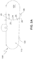
- FIG. 2A is a perspective view of a propane fuel storage tank having a plurality of fluid level sensor units mounted thereon in accordance with the first embodiment of the present invention.
- FIG. 2B is an end plan view of the storage tank of FIG. 2A having fluid level sensor units mounted thereon, as well as a base station which is part of the fluid level monitoring kit according to the first embodiment.
- FIG. 3 is a detailed cross-sectional view of a primary sensor unit shown mounted on a tank wall.
- FIG. 4 is a schematic diagram of the primary sensor unit of FIG. 3 .
- FIG. 5 is a schematic diagram of a control module or base station which is a component of the kit of FIG. 1 .
- FIG. 6 is a simplified schematic diagram of a fluid level monitoring kit according to a second embodiment of the present invention.
- FIG. 7 is an end plan view of the storage tank of FIG. 2A having fluid level sensor units mounted thereon interconnected by connecting cables, as well as a base station which is part of the fluid level monitoring kit according to the second embodiment.
- FIG. 8 is a detailed cross-sectional view of a secondary sensor unit shown mounted on a tank wall.
- FIG. 9 is a schematic diagram showing both the primary sensor unit and the secondary sensor units according to the second embodiment hereof.
- FIG. 10 is a schematic diagram of a control module or base station which is a component of the kit of FIG. 6 .
- FIG. 12 is a schematic diagram showing both the primary sensor unit and the secondary sensor units according to the third embodiment hereof.
- kit 10 according to the present invention can be retrofitted on existing tanks, with minimal or no modification of, or intrusion into such tanks.
- the kit 10 includes a plurality of sensor units, such as those shown at 20 , 22 , 24 , 26 and 28 , as well as a control module or base station 30 .
- a power source typically either a battery 34 or batteries.
- the sensor unit 20 may be powered from a conventional 110 volt electrical outlet.
- the circuit board 36 includes a switch for starting and stopping the timer in response to information from the base station 30 .
- the switch may be a step programmed into the microprocessor 38 .
- This communication device may include one or more of the following Bluetooth, Wi-Fi, Radio Frequency (RF), Infrared sending and/or receiving unit, ANT+ Device. Cellular or cellular data, USB, serial, parallel, FireWire ⁇ or another wired interface.
- RF Radio Frequency
- ANT+ Device Cellular or cellular data, USB, serial, parallel, FireWire ⁇ or another wired interface.
- the communication device(s) 42 may be configured to communicate directly to the internet via one or more of the following: Bluetooth, Wi-Fi, Ethernet, Cellular or cellular data, Satellite, Radio Frequency (RF), Infrared sending and/or receiving unit, ANT+ Device, USB, serial, parallel, FireWire ⁇ or another wired interface.
- Bluetooth Wi-Fi
- Ethernet Cellular or cellular data
- Satellite Radio Frequency
- RF Radio Frequency
- Infrared sending and/or receiving unit ANT+ Device
- USB serial, parallel, FireWire ⁇ or another wired interface.
- Ambient temperature sensor 50 for sensing the general temperature in the area.
- Infrared temperature sensor 52 near the opening of the housing, for sensing a localized temperature of the tank's outer wall 110 in the immediate area of the sensor unit 20 .
- the outer wall temperature will be slightly cooler than the ambient temperature if the area inside of the tank, next to the sensor unit 20 , has fluid in contact with the wall.
- a generally horizontally-oriented propane storage tank is shown generally at 100 , with a primary sensor unit 20 provided for sensing a full level of the tank, is attached to an outer surface of an outside wall 110 of the tank, at or close to the top of the tank.
- the propane tank is used as an example, but the kit, system and methods according to the present invention may be used on any fluid storage tank which exhibits a measurable temperature change of the tank wall between fluid present next to the tank wall and fluid absent next to the tank wall.
- the primary sensor unit 20 functions by measuring the temperature of the outside wall 110 of the tank 100 , where it is mounted, at a continuous predefined time interval, and compares that temperature to the ambient temperature. If the outside wall of the tank is less than the ambient temperature by a predetermined amount, then that indicates that propane, or the other liquid present in the tank, is present at that level.
- Each of the sensor units provides information which enables this temperature comparison to be made, and either the control unit inside of the sensor unit or the base station 30 determines if stored liquid is present at the various levels of each sensor unit.
- the invention according to the first aspect includes a control module 30 , and a plurality of primary sensor units such as those shown at 20 , 22 , 24 , 26 and 28 .
- the base station 30 may be a cell phone or may be a separate, standalone unit. It may be located as part of a transmitter or as a standalone unit.
- the control module or base station 30 may individually communicate with each of the sensor units 20 , 22 , 24 , 26 and 28 .
- the base station 30 may be located remotely from the tank 100 and the sensor units, such as at a heated indoor location relatively close to the tank.
- the control module or base station 30 includes a circuit board having a microprocessor 44 with a memory unit thereon, and a transmitter 46 for communicating with an external communications device, such as a cell phone or an internet connection.
- the microprocessor 44 of the control module includes a timer, a wake-up circuit, and a program for reading all of the sensor units and recording such sensor readings along with the time and date of each reading.
- the base station 30 is provided with a power source 48 , which may be a battery or alternatively, which may be a plug for connecting to standard 110 volt AC power.
- the processor 44 of the base station 30 records readings of the sensor units 20 , 22 , 24 , 26 , and 28 at specified intervals, such as daily, weekly or a longer interval.
- the kit 112 is provided for use in retrofitting an existing fluid storage tank, such as that shown at 100 in FIGS. 2A-2B , to monitor and report on a fluid level in the tank 100 .
- the tank 100 may be an existing fluid storage tank, such as a tank used for storing liquid propane, liquefied natural gas (LNG) or other fluid which is stored in a tank, to monitor a fluid level in the tank.
- LNG liquefied natural gas
- kit 112 according to the present invention can be retrofitted on existing fluid storage tanks, with minimal or no modification of, or intrusion into such tanks.
- kits 112 may be used to monitor fluid levels in a plurality of individual tanks, and may be electronically coordinated to form a monitoring system according to the invention.
- the kit according to the second embodiment includes a control module or base station 130 , a primary sensor unit 120 and a plurality of secondary sensor units such as those shown at 122 , 124 , 126 and 128 . All of the secondary sensor units 122 , 124 , 126 and 128 may be internally identical to one another, but the individual sensor units are used to measure fluid level at different heights on the tank 100 , as shown in FIG. 7 .
- Detailed structure of the primary sensor unit 120 is the same as the structure of the sensor unit 20 shown in FIGS. 4 and 5 , including the components as previously described herein.
- a generally horizontally-oriented propane storage tank is shown generally at 100 , with a primary sensor unit 120 attached to an outer surface of an outside wall 110 of the tank, at or close to the top of the tank.
- the tank 100 is well known and conventional, and does not form a part of the present invention, per se.
- the secondary sensor units 122 , 124 , 126 , and 128 are also shown attached to the outside wall 110 of the tank 100 at different height levels thereon, corresponding to 3 ⁇ 4 full, 1 ⁇ 2 full, 1 ⁇ 4 full, and empty. All of the sensor units 120 , 122 , 124 , 126 , and 128 are shown interconnected by connecting cables 125 which permit electronic communication with the primary sensor unit 120 .
- wireless communication hardware such as Bluetooth may be used instead of the connecting cables 125 .
- the base station 130 may be a cell phone or may be a separate, standalone unit. It may be located as part of the transmitter or as a standalone unit.
- the control module or base station 130 may be in electronic communication with the primary sensor unit 120 , or may communicate with the sensor units 120 , 122 , 124 , 126 and 128 via the communications link of the primary sensor unit. Where the control module 130 communicates with the primary sensor unit 120 , a secondary communications link such as the connecting cables 125 , which may include wiring or a fiber optic connection, is provided between the primary sensor unit 120 and the secondary sensor units 122 , 124 , 126 and 128 .
- the control module 130 is essentially the same as the control module or base station 30 previously described in connection with the first embodiment.
- Each of the secondary sensor units functions by measuring the temperature of the outside wall 110 of the tank 100 , where it is mounted, at a continuous predefined time interval, and compares that temperature to the ambient temperature read at the primary sensor unit 120 . If the outside wall 110 of the tank 100 is less than the ambient temperature by a predetermined amount, then that indicates that propane, or the other liquid present in the tank, is present at that level. Each of the sensor units makes this temperature comparison and determines if propane, or the other liquid present in the tank, is present at the various levels of each sensor unit. This information is then transmitted from the primary sensor unit 120 to the base station 30 . This base station will then forward the information to the tank user or provider at a predetermined interval or as requested. This may be completed by email or by other communication protocol.
- each of the secondary sensor units has some features in common with the primary sensor unit 20 described in connection with the first embodiment, including a weather-resistant housing 132 having an opening 133 formed therein and having a hollow space formed therein in communication with the opening, a weather-resistant seal 137 attached to the housing 132 and surrounding the opening, attachment structure 139 for attaching the housing to a wall 110 of the tank 100 , an infrared sensor 152 disposed in the housing 132 proximate the opening 133 ; and a communications link 125 in contact with the housing, for communicating with the primary sensor unit 120 or with the control module 130 .
- the base station 30 is capable of two-way communications with other supported devices (i.e. phone, tablet, laptop, workstation) using one or more appropriate protocols, in order to make programmatic changes (upgrades/patches), add/remove features, and transfer data to and from the device by utilizing custom software/firmware.
- other supported devices i.e. phone, tablet, laptop, workstation
- programmatic changes upgrades/patches
- add/remove features add/remove features
- the kit 212 is provided for use in retrofitting an existing fluid storage tank, such as that shown at 100 in FIGS. 2A-2B , to monitor and report on a fluid level in the tank 100 .
- the tank 100 may be an existing fluid storage tank, such as a tank used for storing liquid propane, liquefied natural gas (LNG) or other fluid stored in a fluid storage tank, to monitor a fluid level in the tank.
- LNG liquefied natural gas
- kit 212 can be retrofitted on existing tanks, with minimal or no modification of, or intrusion into such tanks.
- kits 212 may be used to monitor fluid levels in a plurality of individual tanks, and may be electronically coordinated to form a monitoring system according to the invention.
- Detailed structure of the primary sensor unit 20 begins with structure similar to that shown in FIGS. 4 and 5 , with the additional feature that in this third embodiment, the base station has now been incorporated into the internal structure of the primary sensor unit 220 .
- the secondary sensor units 222 , 24 , 226 , and 228 are also attached to the outside wall 110 of the tank 100 at different height levels thereon, corresponding to 3 ⁇ 4 full, 1 ⁇ 2 full, 1 ⁇ 4 full, and empty. All of the sensor units 220 , 222 , 224 , 226 , and 228 are shown interconnected by communication connectors 225 . Optionally, wireless communication hardware, such as Bluetooth may be used instead of the connectors 225 .
- the primary sensor unit 220 includes a circuit board having a microprocessor 238 and a memory unit thereon, and a transmitter 242 for communicating with an external communications device, such as a cell phone or an internet connection.
- the microprocessor 238 of the primary sensor unit 220 includes a timer, a wake-up circuit, and a program for reading all of the sensor units and recording such sensor readings along with the time and date of each reading.
- the microprocessor 238 is designed to remain off whenever the tool is not in use to extend the useful life of the battery, allowing the apparatus to use a relatively small battery.
- the processor records readings of the sensor units 220 , 222 , 224 , 226 , and 228 at specified intervals, such as daily, weekly or a longer interval.
- the circuit board of the primary sensor unit 220 includes a switch for starting and stopping the timer as preselected.
- the switch may be a step programmed into the microprocessor 238 .
- the transmitting unit functions by measuring the temperature of the outside wall of the propane tank, where it is mounted, at a continuous predefined time interval, and compares that temperature to the ambient temperature. If the outside wall of the tank is less than the ambient temperature by a predetermined amount, then that would indicate that propane is present at that level.
- Each of the transmitters makes this temperature comparison and determines if propane, or other fluid stored in the tank, is present at the various levels of each sensor unit. This information is then transmitted from the transmitter 242 to the user or manager at a predetermined interval or as requested. This may be completed by email or by other communication protocol.
- Each of the secondary sensor units has some features in common with the primary sensor unit, including a weather-resistant housing having an opening formed therein and having a hollow space formed therein in communication with the opening a weather-resistant seal attached to the housing and surrounding the opening, attachment structure for attaching the housing to a wall of the tank, an infrared sensor disposed in the housing proximate the opening; and a communications link in the housing for communicating with the primary sensor unit or with the control module.
- the primary sensor unit 220 is capable of two-way communications with other supported devices (i.e. phone, tablet, laptop, workstation) using one or more appropriate protocols, in order to make programmatic changes (upgrades/patches), add/remove features, and transfer data to and from the device by utilizing custom software/firmware.
- a system for monitoring fluid levels in multiple fluid storage tanks according to the present invention could be provided where each tank in the system is provided with a fluid level monitoring apparatus, such as the kit 10 described herein.
- the system includes a main control processor which intermittently receives input data from each of the base stations for the tanks included in the system, including data representing the physical location of each tank.
- the main control processor includes a non-volatile memory which stores and reports on data regarding fluid levels in each of the tanks.
- the present invention also relates to a method of monitoring fluid levels over time in a fluid storage tank, using the equipment from one of the kits according to the invention.
- the method includes a first step of mounting sensor units at different levels on a tank wall using sensor units from the kit as previously described herein.
- the method also includes a second step of activating the base station to enable sensor readouts from each sensor unit.
- Such activation may include calibrating the base station to register each of the sensor units with its assigned tank fluid level.
- the method also includes a subsequent step of connecting the base station to the internet or to a cell phone, so that the sensed fluid level in the tank can be remotely monitored and observed.
- the method may include a step of sending an alert message to a user when a tank is at a low level, and may further include a step of robotically ordering a refill of a low tank.
Landscapes
- Physics & Mathematics (AREA)
- Business, Economics & Management (AREA)
- General Physics & Mathematics (AREA)
- Fluid Mechanics (AREA)
- Thermal Sciences (AREA)
- Engineering & Computer Science (AREA)
- Economics (AREA)
- Human Resources & Organizations (AREA)
- Operations Research (AREA)
- Finance (AREA)
- Emergency Management (AREA)
- Entrepreneurship & Innovation (AREA)
- Accounting & Taxation (AREA)
- Marketing (AREA)
- Development Economics (AREA)
- Quality & Reliability (AREA)
- Strategic Management (AREA)
- Tourism & Hospitality (AREA)
- General Business, Economics & Management (AREA)
- Theoretical Computer Science (AREA)
- Filling Or Discharging Of Gas Storage Vessels (AREA)
Abstract
Description
Claims (13)
Priority Applications (1)
| Application Number | Priority Date | Filing Date | Title |
|---|---|---|---|
| US15/847,352 US11054296B2 (en) | 2017-12-19 | 2017-12-19 | Level sensor kit for use with a liquid storage tank, system incorporating same, and methods of using same |
Applications Claiming Priority (1)
| Application Number | Priority Date | Filing Date | Title |
|---|---|---|---|
| US15/847,352 US11054296B2 (en) | 2017-12-19 | 2017-12-19 | Level sensor kit for use with a liquid storage tank, system incorporating same, and methods of using same |
Publications (2)
| Publication Number | Publication Date |
|---|---|
| US20190186977A1 US20190186977A1 (en) | 2019-06-20 |
| US11054296B2 true US11054296B2 (en) | 2021-07-06 |
Family
ID=66814319
Family Applications (1)
| Application Number | Title | Priority Date | Filing Date |
|---|---|---|---|
| US15/847,352 Expired - Fee Related US11054296B2 (en) | 2017-12-19 | 2017-12-19 | Level sensor kit for use with a liquid storage tank, system incorporating same, and methods of using same |
Country Status (1)
| Country | Link |
|---|---|
| US (1) | US11054296B2 (en) |
Cited By (1)
| Publication number | Priority date | Publication date | Assignee | Title |
|---|---|---|---|---|
| RU2797783C1 (en) * | 2021-12-16 | 2023-06-08 | Общество с ограниченной ответственностью "Газпром трансгаз Ухта" | Method for determining presence of liquid in the column of an underground ball valve and device for its implementation |
Families Citing this family (6)
| Publication number | Priority date | Publication date | Assignee | Title |
|---|---|---|---|---|
| AU2020363987A1 (en) * | 2019-10-09 | 2022-04-21 | Roth River, Inc. | Systems and methods for remotely monitoring inventory and product life-cycle |
| DE102020201954B4 (en) * | 2020-02-17 | 2023-08-10 | Vega Grieshaber Kg | Protective device for sealing a sensor device |
| KR102715722B1 (en) * | 2021-11-26 | 2024-10-11 | 한국가스안전공사 | Apparatus for measuring external temperature of gas container |
| CN114485794A (en) * | 2022-01-22 | 2022-05-13 | 成都天奥电子股份有限公司 | Many networks of LNG jar body danger article transportation detecting system |
| WO2024218537A1 (en) * | 2023-04-18 | 2024-10-24 | Volvo Truck Corporation | Temperature-based level gauge for a vessel |
| KR20250009252A (en) * | 2023-07-10 | 2025-01-17 | 현대자동차주식회사 | Apparatus for measuring a amount of hydrogen stored in a container and method thereof |
Citations (8)
| Publication number | Priority date | Publication date | Assignee | Title |
|---|---|---|---|---|
| US20010032506A1 (en) * | 2000-02-08 | 2001-10-25 | Keller John M. | Method and apparatus for monitoring liquid level in a container |
| US6336362B1 (en) | 1998-01-22 | 2002-01-08 | Roy A. Duenas | Method and system for measuring and remotely reporting the liquid level of tanks and the usage thereof |
| US6925872B2 (en) | 2001-11-19 | 2005-08-09 | Anthony J. Hadala | Temperature-sensing device for determining the level of a fluid |
| US20050193839A1 (en) * | 2004-03-05 | 2005-09-08 | Daniel Gronvall | Self adjusting sensor mounting device |
| US20080236275A1 (en) * | 2002-06-11 | 2008-10-02 | Intelligent Technologies International, Inc. | Remote Monitoring of Fluid Storage Tanks |
| US20150323369A1 (en) * | 2014-05-09 | 2015-11-12 | Marqmetrix, Inc. | Constant Fluid Level and Equipment Monitor |
| US20180111145A1 (en) * | 2016-10-24 | 2018-04-26 | Heiner Ophardt | System for Monitoring Fluid in a Fluid Dispenser |
| US20190083298A1 (en) * | 2017-09-21 | 2019-03-21 | Michael W. Starkweather | Whole body cryotherapy system |
-
2017
- 2017-12-19 US US15/847,352 patent/US11054296B2/en not_active Expired - Fee Related
Patent Citations (8)
| Publication number | Priority date | Publication date | Assignee | Title |
|---|---|---|---|---|
| US6336362B1 (en) | 1998-01-22 | 2002-01-08 | Roy A. Duenas | Method and system for measuring and remotely reporting the liquid level of tanks and the usage thereof |
| US20010032506A1 (en) * | 2000-02-08 | 2001-10-25 | Keller John M. | Method and apparatus for monitoring liquid level in a container |
| US6925872B2 (en) | 2001-11-19 | 2005-08-09 | Anthony J. Hadala | Temperature-sensing device for determining the level of a fluid |
| US20080236275A1 (en) * | 2002-06-11 | 2008-10-02 | Intelligent Technologies International, Inc. | Remote Monitoring of Fluid Storage Tanks |
| US20050193839A1 (en) * | 2004-03-05 | 2005-09-08 | Daniel Gronvall | Self adjusting sensor mounting device |
| US20150323369A1 (en) * | 2014-05-09 | 2015-11-12 | Marqmetrix, Inc. | Constant Fluid Level and Equipment Monitor |
| US20180111145A1 (en) * | 2016-10-24 | 2018-04-26 | Heiner Ophardt | System for Monitoring Fluid in a Fluid Dispenser |
| US20190083298A1 (en) * | 2017-09-21 | 2019-03-21 | Michael W. Starkweather | Whole body cryotherapy system |
Non-Patent Citations (1)
| Title |
|---|
| Removable Accu-Level Propane Tank Gauge with Magnetic back, https://www.walmart.com/ip/Removable-Accu-Level-Propane-Tank-Gauge-with-Magnetic-back/119088994, retrieved on Dec. 12, 2017. |
Cited By (1)
| Publication number | Priority date | Publication date | Assignee | Title |
|---|---|---|---|---|
| RU2797783C1 (en) * | 2021-12-16 | 2023-06-08 | Общество с ограниченной ответственностью "Газпром трансгаз Ухта" | Method for determining presence of liquid in the column of an underground ball valve and device for its implementation |
Also Published As
| Publication number | Publication date |
|---|---|
| US20190186977A1 (en) | 2019-06-20 |
Similar Documents
| Publication | Publication Date | Title |
|---|---|---|
| US11054296B2 (en) | Level sensor kit for use with a liquid storage tank, system incorporating same, and methods of using same | |
| US9851053B2 (en) | Propane tank continuous monitoring system | |
| US20180073682A1 (en) | Propane tank continuous monitoring system | |
| US5211678A (en) | Apparatus, method and system for monitoring fluid | |
| CN104567267B (en) | The setting system of the method to set up of article storage period and article storage period | |
| US20110000295A1 (en) | Remote level gauge adapted for liquid fuel tank | |
| CN104574036B (en) | Handle the method and server of article storage apparatus data | |
| US20180132643A1 (en) | An Intelligent Liquid Intake Measurement Device | |
| US10837814B1 (en) | Smart gas cylinder cap | |
| US11803215B2 (en) | Removable display and control module for a measuring device | |
| WO2016142941A1 (en) | An intelligent liquid intake measurement device | |
| US11938360B2 (en) | Retrofit fire extinguisher apparatus | |
| US20160377474A1 (en) | Wireless oil tank level reporting device, system and method | |
| CN104732321A (en) | Article storage system and preservation method and device for article storage data | |
| MX2010010741A (en) | Equipment for logging and transmitting measured values of physical quantities, and measurement sensor for such equipment. | |
| US20240237630A1 (en) | Bait scale device and remote monitoring device configured to receive signals from a bait scale device | |
| US5272920A (en) | Apparatus, method and system for monitoring fluid | |
| CN104236727A (en) | Containing box control system and method | |
| CN112834063A (en) | A temperature measuring device and measuring system for power transformers that can be checked online | |
| US12576011B2 (en) | Milk minder methodologies and systems | |
| JP2006011642A (en) | Transceiver, gas leakage detection system using same transceiver and guide value fluctuation detecting device to be used for same system | |
| ITRM20130297A1 (en) | MONITORING DEVICE FOR THE HEALTH STATUS OF A CRITICAL SYSTEM WITH A LIMITED LIFE INCLUDING A DATA DISPLAY UNIT | |
| GB2542392A (en) | An oil tank monitoring system | |
| US11959790B2 (en) | Cylinder storage cage monitoring system | |
| US20240385024A1 (en) | Exterior gauge component for fuel level monitoring that is compatible with different tank gauge heads |
Legal Events
| Date | Code | Title | Description |
|---|---|---|---|
| AS | Assignment |
Owner name: MABEE ENGINEERED SOLUTIONS, INC., MICHIGAN Free format text: ASSIGNMENT OF ASSIGNORS INTEREST;ASSIGNORS:MABEE, BRIAN D.;MABEE, AUSTIN M.;REEL/FRAME:044440/0146 Effective date: 20171212 |
|
| FEPP | Fee payment procedure |
Free format text: ENTITY STATUS SET TO UNDISCOUNTED (ORIGINAL EVENT CODE: BIG.); ENTITY STATUS OF PATENT OWNER: SMALL ENTITY |
|
| FEPP | Fee payment procedure |
Free format text: ENTITY STATUS SET TO SMALL (ORIGINAL EVENT CODE: SMAL); ENTITY STATUS OF PATENT OWNER: SMALL ENTITY |
|
| STPP | Information on status: patent application and granting procedure in general |
Free format text: DOCKETED NEW CASE - READY FOR EXAMINATION |
|
| STPP | Information on status: patent application and granting procedure in general |
Free format text: NON FINAL ACTION MAILED |
|
| STPP | Information on status: patent application and granting procedure in general |
Free format text: RESPONSE TO NON-FINAL OFFICE ACTION ENTERED AND FORWARDED TO EXAMINER |
|
| STPP | Information on status: patent application and granting procedure in general |
Free format text: NOTICE OF ALLOWANCE MAILED -- APPLICATION RECEIVED IN OFFICE OF PUBLICATIONS |
|
| STPP | Information on status: patent application and granting procedure in general |
Free format text: PUBLICATIONS -- ISSUE FEE PAYMENT RECEIVED |
|
| STPP | Information on status: patent application and granting procedure in general |
Free format text: PUBLICATIONS -- ISSUE FEE PAYMENT VERIFIED |
|
| STCF | Information on status: patent grant |
Free format text: PATENTED CASE |
|
| FEPP | Fee payment procedure |
Free format text: MAINTENANCE FEE REMINDER MAILED (ORIGINAL EVENT CODE: REM.); ENTITY STATUS OF PATENT OWNER: SMALL ENTITY |
|
| LAPS | Lapse for failure to pay maintenance fees |
Free format text: PATENT EXPIRED FOR FAILURE TO PAY MAINTENANCE FEES (ORIGINAL EVENT CODE: EXP.); ENTITY STATUS OF PATENT OWNER: SMALL ENTITY |
|
| STCH | Information on status: patent discontinuation |
Free format text: PATENT EXPIRED DUE TO NONPAYMENT OF MAINTENANCE FEES UNDER 37 CFR 1.362 |
|
| FP | Lapsed due to failure to pay maintenance fee |
Effective date: 20250706 |