US11052777B2 - Method of charging electric autonomous moving body - Google Patents
Method of charging electric autonomous moving body Download PDFInfo
- Publication number
- US11052777B2 US11052777B2 US16/256,575 US201916256575A US11052777B2 US 11052777 B2 US11052777 B2 US 11052777B2 US 201916256575 A US201916256575 A US 201916256575A US 11052777 B2 US11052777 B2 US 11052777B2
- Authority
- US
- United States
- Prior art keywords
- charging
- autonomous moving
- charger unit
- robots
- robot
- Prior art date
- Legal status (The legal status is an assumption and is not a legal conclusion. Google has not performed a legal analysis and makes no representation as to the accuracy of the status listed.)
- Expired - Fee Related, expires
Links
Images


Classifications
-
- H—ELECTRICITY
- H01—ELECTRIC ELEMENTS
- H01M—PROCESSES OR MEANS, e.g. BATTERIES, FOR THE DIRECT CONVERSION OF CHEMICAL ENERGY INTO ELECTRICAL ENERGY
- H01M10/00—Secondary cells; Manufacture thereof
- H01M10/42—Methods or arrangements for servicing or maintenance of secondary cells or secondary half-cells
- H01M10/44—Methods for charging or discharging
- H01M10/441—Methods for charging or discharging for several batteries or cells simultaneously or sequentially
-
- H02J7/50—
-
- B—PERFORMING OPERATIONS; TRANSPORTING
- B60—VEHICLES IN GENERAL
- B60L—PROPULSION OF ELECTRICALLY-PROPELLED VEHICLES; SUPPLYING ELECTRIC POWER FOR AUXILIARY EQUIPMENT OF ELECTRICALLY-PROPELLED VEHICLES; ELECTRODYNAMIC BRAKE SYSTEMS FOR VEHICLES IN GENERAL; MAGNETIC SUSPENSION OR LEVITATION FOR VEHICLES; MONITORING OPERATING VARIABLES OF ELECTRICALLY-PROPELLED VEHICLES; ELECTRIC SAFETY DEVICES FOR ELECTRICALLY-PROPELLED VEHICLES
- B60L53/00—Methods of charging batteries, specially adapted for electric vehicles; Charging stations or on-board charging equipment therefor; Exchange of energy storage elements in electric vehicles
- B60L53/10—Methods of charging batteries, specially adapted for electric vehicles; Charging stations or on-board charging equipment therefor; Exchange of energy storage elements in electric vehicles characterised by the energy transfer between the charging station and the vehicle
- B60L53/14—Conductive energy transfer
- B60L53/16—Connectors, e.g. plugs or sockets, specially adapted for charging electric vehicles
-
- B—PERFORMING OPERATIONS; TRANSPORTING
- B60—VEHICLES IN GENERAL
- B60L—PROPULSION OF ELECTRICALLY-PROPELLED VEHICLES; SUPPLYING ELECTRIC POWER FOR AUXILIARY EQUIPMENT OF ELECTRICALLY-PROPELLED VEHICLES; ELECTRODYNAMIC BRAKE SYSTEMS FOR VEHICLES IN GENERAL; MAGNETIC SUSPENSION OR LEVITATION FOR VEHICLES; MONITORING OPERATING VARIABLES OF ELECTRICALLY-PROPELLED VEHICLES; ELECTRIC SAFETY DEVICES FOR ELECTRICALLY-PROPELLED VEHICLES
- B60L53/00—Methods of charging batteries, specially adapted for electric vehicles; Charging stations or on-board charging equipment therefor; Exchange of energy storage elements in electric vehicles
- B60L53/30—Constructional details of charging stations
-
- G—PHYSICS
- G05—CONTROLLING; REGULATING
- G05D—SYSTEMS FOR CONTROLLING OR REGULATING NON-ELECTRIC VARIABLES
- G05D1/00—Control of position, course, altitude or attitude of land, water, air or space vehicles, e.g. using automatic pilots
- G05D1/0088—Control of position, course, altitude or attitude of land, water, air or space vehicles, e.g. using automatic pilots characterized by the autonomous decision making process, e.g. artificial intelligence, predefined behaviours
-
- H—ELECTRICITY
- H02—GENERATION; CONVERSION OR DISTRIBUTION OF ELECTRIC POWER
- H02J—CIRCUIT ARRANGEMENTS OR SYSTEMS FOR SUPPLYING OR DISTRIBUTING ELECTRIC POWER; SYSTEMS FOR STORING ELECTRIC ENERGY
- H02J7/00—Circuit arrangements for charging or depolarising batteries or for supplying loads from batteries
- H02J7/0013—Circuit arrangements for charging or depolarising batteries or for supplying loads from batteries acting upon several batteries simultaneously or sequentially
-
- H02J7/0027—
-
- H—ELECTRICITY
- H02—GENERATION; CONVERSION OR DISTRIBUTION OF ELECTRIC POWER
- H02J—CIRCUIT ARRANGEMENTS OR SYSTEMS FOR SUPPLYING OR DISTRIBUTING ELECTRIC POWER; SYSTEMS FOR STORING ELECTRIC ENERGY
- H02J7/00—Circuit arrangements for charging or depolarising batteries or for supplying loads from batteries
- H02J7/0042—Circuit arrangements for charging or depolarising batteries or for supplying loads from batteries characterised by the mechanical construction
-
- H02J7/70—
-
- H—ELECTRICITY
- H01—ELECTRIC ELEMENTS
- H01M—PROCESSES OR MEANS, e.g. BATTERIES, FOR THE DIRECT CONVERSION OF CHEMICAL ENERGY INTO ELECTRICAL ENERGY
- H01M10/00—Secondary cells; Manufacture thereof
- H01M10/42—Methods or arrangements for servicing or maintenance of secondary cells or secondary half-cells
- H01M10/425—Structural combination with electronic components, e.g. electronic circuits integrated to the outside of the casing
- H01M10/4257—Smart batteries, e.g. electronic circuits inside the housing of the cells or batteries
-
- H—ELECTRICITY
- H02—GENERATION; CONVERSION OR DISTRIBUTION OF ELECTRIC POWER
- H02J—CIRCUIT ARRANGEMENTS OR SYSTEMS FOR SUPPLYING OR DISTRIBUTING ELECTRIC POWER; SYSTEMS FOR STORING ELECTRIC ENERGY
- H02J1/00—Circuit arrangements for DC mains or DC distribution networks
-
- Y—GENERAL TAGGING OF NEW TECHNOLOGICAL DEVELOPMENTS; GENERAL TAGGING OF CROSS-SECTIONAL TECHNOLOGIES SPANNING OVER SEVERAL SECTIONS OF THE IPC; TECHNICAL SUBJECTS COVERED BY FORMER USPC CROSS-REFERENCE ART COLLECTIONS [XRACs] AND DIGESTS
- Y02—TECHNOLOGIES OR APPLICATIONS FOR MITIGATION OR ADAPTATION AGAINST CLIMATE CHANGE
- Y02E—REDUCTION OF GREENHOUSE GAS [GHG] EMISSIONS, RELATED TO ENERGY GENERATION, TRANSMISSION OR DISTRIBUTION
- Y02E60/00—Enabling technologies; Technologies with a potential or indirect contribution to GHG emissions mitigation
- Y02E60/10—Energy storage using batteries
-
- Y—GENERAL TAGGING OF NEW TECHNOLOGICAL DEVELOPMENTS; GENERAL TAGGING OF CROSS-SECTIONAL TECHNOLOGIES SPANNING OVER SEVERAL SECTIONS OF THE IPC; TECHNICAL SUBJECTS COVERED BY FORMER USPC CROSS-REFERENCE ART COLLECTIONS [XRACs] AND DIGESTS
- Y02—TECHNOLOGIES OR APPLICATIONS FOR MITIGATION OR ADAPTATION AGAINST CLIMATE CHANGE
- Y02T—CLIMATE CHANGE MITIGATION TECHNOLOGIES RELATED TO TRANSPORTATION
- Y02T10/00—Road transport of goods or passengers
- Y02T10/60—Other road transportation technologies with climate change mitigation effect
- Y02T10/70—Energy storage systems for electromobility, e.g. batteries
-
- Y—GENERAL TAGGING OF NEW TECHNOLOGICAL DEVELOPMENTS; GENERAL TAGGING OF CROSS-SECTIONAL TECHNOLOGIES SPANNING OVER SEVERAL SECTIONS OF THE IPC; TECHNICAL SUBJECTS COVERED BY FORMER USPC CROSS-REFERENCE ART COLLECTIONS [XRACs] AND DIGESTS
- Y02—TECHNOLOGIES OR APPLICATIONS FOR MITIGATION OR ADAPTATION AGAINST CLIMATE CHANGE
- Y02T—CLIMATE CHANGE MITIGATION TECHNOLOGIES RELATED TO TRANSPORTATION
- Y02T10/00—Road transport of goods or passengers
- Y02T10/60—Other road transportation technologies with climate change mitigation effect
- Y02T10/7072—Electromobility specific charging systems or methods for batteries, ultracapacitors, supercapacitors or double-layer capacitors
-
- Y—GENERAL TAGGING OF NEW TECHNOLOGICAL DEVELOPMENTS; GENERAL TAGGING OF CROSS-SECTIONAL TECHNOLOGIES SPANNING OVER SEVERAL SECTIONS OF THE IPC; TECHNICAL SUBJECTS COVERED BY FORMER USPC CROSS-REFERENCE ART COLLECTIONS [XRACs] AND DIGESTS
- Y02—TECHNOLOGIES OR APPLICATIONS FOR MITIGATION OR ADAPTATION AGAINST CLIMATE CHANGE
- Y02T—CLIMATE CHANGE MITIGATION TECHNOLOGIES RELATED TO TRANSPORTATION
- Y02T90/00—Enabling technologies or technologies with a potential or indirect contribution to GHG emissions mitigation
- Y02T90/10—Technologies relating to charging of electric vehicles
- Y02T90/12—Electric charging stations
-
- Y—GENERAL TAGGING OF NEW TECHNOLOGICAL DEVELOPMENTS; GENERAL TAGGING OF CROSS-SECTIONAL TECHNOLOGIES SPANNING OVER SEVERAL SECTIONS OF THE IPC; TECHNICAL SUBJECTS COVERED BY FORMER USPC CROSS-REFERENCE ART COLLECTIONS [XRACs] AND DIGESTS
- Y02—TECHNOLOGIES OR APPLICATIONS FOR MITIGATION OR ADAPTATION AGAINST CLIMATE CHANGE
- Y02T—CLIMATE CHANGE MITIGATION TECHNOLOGIES RELATED TO TRANSPORTATION
- Y02T90/00—Enabling technologies or technologies with a potential or indirect contribution to GHG emissions mitigation
- Y02T90/10—Technologies relating to charging of electric vehicles
- Y02T90/14—Plug-in electric vehicles
-
- Y—GENERAL TAGGING OF NEW TECHNOLOGICAL DEVELOPMENTS; GENERAL TAGGING OF CROSS-SECTIONAL TECHNOLOGIES SPANNING OVER SEVERAL SECTIONS OF THE IPC; TECHNICAL SUBJECTS COVERED BY FORMER USPC CROSS-REFERENCE ART COLLECTIONS [XRACs] AND DIGESTS
- Y02—TECHNOLOGIES OR APPLICATIONS FOR MITIGATION OR ADAPTATION AGAINST CLIMATE CHANGE
- Y02T—CLIMATE CHANGE MITIGATION TECHNOLOGIES RELATED TO TRANSPORTATION
- Y02T90/00—Enabling technologies or technologies with a potential or indirect contribution to GHG emissions mitigation
- Y02T90/10—Technologies relating to charging of electric vehicles
- Y02T90/16—Information or communication technologies improving the operation of electric vehicles
Definitions
- the present disclosure relates to a method of charging an electric autonomous moving body.
- Japanese Unexamined Patent Application Publication No. 2013-090416 discloses a technique for charging a battery mounted on a moving body.
- batteries of a plurality of moving bodies can be charged by providing a plurality of power supply units and a plurality of power feed wires capable of connecting different batteries to the respective power supply units.
- a changeover switch for integrating or separating the plurality of power supply units when a battery of one moving body is charged, this battery can be rapidly charged by the integrated plurality of power supply units.
- the plurality of moving bodies are aligned in a serial state, the power supply unit and the plurality of moving bodies are electrically connected to each other, and the batteries of the plurality of moving bodies are charged by one power supply unit.
- the batteries of the plurality of moving bodies need to be charged within a range of an allowable current of the power supply unit and the power supply line.
- the present disclosure has been made in view of the aforementioned problems and provides a method of charging an electric autonomous moving body capable of performing charging within the range of the allowable current of the charger unit and the power supply line in the case in which the plurality of electric autonomous moving bodies are aligned in the serial state, the charger unit and the plurality of electric autonomous moving bodies are electrically connected to each other, and the batteries of the plurality of electric autonomous moving bodies are charged by one charger unit.
- a method of charging an electric autonomous moving, body is a method of charging an electric autonomous moving body by a charging system in which a plurality of electric autonomous moving bodies including batteries are aligned in a serial state, a charger unit and the plurality of electric autonomous moving bodies are electrically connected to each other, power is supplied from the charger unit to the respective electric autonomous moving bodies, and the batteries of the plurality of electric autonomous moving bodies are charged, in which
- the charger unit is provided with connection member electrically connected to the electric autonomous moving body,
- each of the electric autonomous moving bodies is provided with a first connection member capable of being electrically connected to the connection member of the charger unit and a second connection member capable of being electrically connected to the first connection member of another one of the electric autonomous moving bodies,
- the charging system includes a controller configured to execute control for switching a charging state and a non-charging, state of the batteries of the respective electric autonomous moving bodies,
- each of the electric autonomous moving bodies includes a communication function
- each of the electric autonomous moving bodies sends charging state information indicating the charging state of the battery of the electric autonomous moving body and the controller executes control for switching the charging state and the non-charging state of the batteries of the respective electric autonomous moving bodies based on the charging state information of the batteries of the respective electric autonomous moving bodies in such a way that the total amount of current that flows through the batteries of the respective electric autonomous, moving bodies does not exceed an allowable current of the charger unit and a power supply line.
- FIG. 1 is an external side view showing one example of an external configuration of a charging system according to a first embodiment
- FIG. 2 is an external side view showing one example of an external configuration of a charger unit according to the first embodiment
- FIG. 3 is an external side view showing another example of the external configuration of the charger unit according to the first embodiment
- FIG. 4 is an external side view showing one example of an external configuration of a robot according to the first embodiment
- FIG. 5 is an external side view showing another example of the external configuration of the robot according to the first embodiment
- FIG. 6 is a block diagram showing one example of a block configuration of the charger unit according to the first embodiment
- FIG. 7 is a block, diagram showing one example of a block configuration of the robot according to the first embodiment
- FIG. 8 is a diagram showing an image of a first-in first-out system
- FIG. 9 is a diagram showing an image of a last-in first-out system
- FIG. 10 is a diagram showing one example of schematic operations in the first-in first-out system in the charging system according to the first embodiment
- FIG. 11 is a diagram showing one example of schematic operations in the last-in first-out system in the charging system according to the first embodiment
- FIG. 12 is a flowchart showing one example of an operation flow when the robot is connected to the charger unit in the robot according to the first embodiment
- FIG. 13 is a flowchart showing one example of an operation flow when the robot is charged in the robot according to the first embodiment
- FIG. 14 is a flowchart showing one example of an operation, flow when the robot is separated from the charger unit in the robot according to the first embodiment
- FIG. 15 is a block diagram showing one example of a block configuration of a charger unit according to a second embodiment
- FIG. 16 is a diagram showing, one example of schematic operations in the first-in first-out system in a charging system according to the second embodiment
- FIG. 17 is a diagram showing one example of schematic operations in the last-in first-out system in the charging system according to the second embodiment
- FIG. 18 is a flowchart showing one example of an operation flow in the charger unit according to the second embodiment.
- FIG. 19 is a diagram showing one example of schematic operations when charger units of two systems are included in the charging system according to the second embodiment
- FIG. 20 is a block diagram showing one example of a block configuration of a management server according to a third embodiment
- FIG. 21 is a diagram showing one example of schematic operations in the first-in first-out system in a charging system according to the third embodiment
- FIG. 22 shows one example of schematic operations in the last-in first-out system in the charging system according to the third embodiment
- FIG. 23 is a flowchart showing one example of an operation flow of the management server according to the third embodiment.
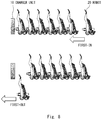
- FIG. 24 is a diagram showing one example of schematic operations when charger units of two systems are included in the charging system according, to the third embodiment.
- FIG. 25 is a block diagram showing one example of a block configuration of a robot according to a fourth embodiment.
- FIG. 26 is a diagram showing one example of schematic operations in a charging system according to the fourth embodiment.
- FIG. 27 is a flowchart showing one example of an operation flow when the robot is connected to the charger unit and it is charged in the robot according to the fourth embodiment;
- FIG. 28 is a flowchart showing one example of an operation flow when the robot is separated from the charger unit in the robot according to the fourth embodiment
- FIG. 29 is an external side view showing one example of an external configuration of a charging system according to a modified example of the first to fourth embodiments.
- FIG. 30 is an external side view showing one example of an external configuration of an electric automobile according to the modified example of the first to fourth embodiments.
- FIG. 1 shows one example of the external configuration of the charging system according to the first embodiment.
- FIG. 1 shows an example in which an electric autonomous moving body is a robot (personal mobility robot) on which a user rides when traveling.
- the electric autonomous moving body according to the present disclosure is not limited to the robot shown in FIG. 1 .
- one charger unit 10 that can charge batteries 205 (see FIG. 7 described later) of a plurality of robots 20 is provided for the plurality of robots 20 including, the batteries 205 .
- the plurality of robots 20 When the batteries 205 of the plurality of robots 20 are charged, the plurality of robots 20 are aligned in a serial state and the plurality of robots 20 are electrically connected with one another, and the robot 20 that is the closest to the charger unit 10 is electrically connected to the charger unit 10 . Then power is supplied from the charger unit 10 to each of the robots 20 and the batteries 205 of the plurality of robots 20 are thus charged. Therefore, the robot 20 that is the closest to the charger unit 10 is supplied with power from the charger unit 10 directly and the other robots 20 are supplied with power from the charger unit 10 indirectly.
- FIGS. 2 and 3 each show one example of the external configuration of the charger unit 10 according to the first embodiment.
- the charger unit 10 includes one of a charging connector 101 shown in FIG. 2 and a non-contact charging terminal 101 A shown in FIG. 3 .
- the charging connector 101 and the non-contact charging terminal 101 A are examples of connection member.
- the charging connector 101 is a connector that can engage with a forward charging connector 201 (described later) of the robot 20 and can be electrically connected thereto in order to supply power to the robot 20 .
- the non-contact charging terminal 101 A is a terminal that can be electrically connected to a forward non-contact charging terminal 201 A (described later) of the robot 20 in a state in which the non-contact charging terminal 101 A does not contact the forward non-contact charging terminal 201 A in such a way that the non-contact charging, terminal 101 A is able to supply power to the robot 20 .
- FIGS. 4 and 5 each show one example of the external configuration of the robot 20 according to the first embodiment.
- the robot 20 includes driving wheels 203 and a steering wheel 204 , and is a personal mobility robot on which a user rides when traveling. Further, the robot 20 includes the forward charging connector 201 and a backward charging connector 202 shown in FIG. 4 or the forward non-contact charging terminal 201 A and a backward non-contact charging terminal 202 A shown in FIG. 5 .
- the forward charging connector 201 and the forward non-contact charging terminal 201 A are examples of first connection member and the backward charging connector 202 and the backward non-contact charging terminal 202 A are examples of second connection member.
- the forward charging connector 201 is a connector that is provided in the front of the body of the robot 20 and can engage with the charging connector 101 of the charger unit 10 and can be electrically connected thereto in order to input the power supplied from the charger unit 10 directly or indirectly.
- the forward non-contact charging terminal 201 A is a terminal that is provided in the front of the body of the robot 20 and can be electrically connected to the non-contact charging terminal 101 A of the charger unit 10 in a state in which they do not contact each other in order to input the power supplied from the charger unit 10 directly or indirectly.
- the backward charging connector 202 is a connector that is provided in the rear of the body of the robot 20 and can engage with the forward charging connector 201 of another robot 20 and can be electrically connected thereto in order to output power to the other robot 20 .
- the backward non-contact charging terminal 202 A is a terminal that is provided in the rear of the body of the robot 20 and can be electrically connected to the forward non-contact charging terminal 201 A of another robot 20 in a state in which they do not contact each other in order to output power to the other robot 20 .
- one of the charging connector 101 and the forward charging connector 201 be a male connector and the other one of them be a female connector, and it does not matter which one of them is the male or the female connector. It is also sufficient that one of the forward charging connector 201 and the backward charging connector 202 be a male connector and the other one of them be a female connector, and it does not matter which one of them is the male or the female connector.
- the charging connector 101 , the forward charging connector 201 , and the backward charging connector 202 include at least wires for supplying power, they may include wires for detecting the electrical connection, wires for performing wired communication with another robot 20 or the like as necessary.
- the robots 20 need to be parked within a positional displacement allowance of the connectors. Therefore, from the viewpoint of reducing the positional displacement, it is more useful to use the non-contact charging terminals (the non-contact charging terminal 101 A, the forward non-contact charging terminal 201 A, and the backward non-contact charging terminal 202 A).
- the non-contact charging terminals when used, the number of electronic circuits increases and the cost increases. Therefore, from the viewpoint of reducing the cost, it is more useful to use the connectors. Therefore, which one of the connectors and the non-contact charging terminals should be used may be determined as appropriate depending on which one of the positional displacement and the cost should be prioritized.
- the direction in which the robots 20 are aligned when the plurality of robots 20 are aligned in the serial state is set as the front-back direction of the robot 20
- the forward charging connector 201 or the forward non-contact charging terminal 201 A is arranged in the front of the body of the robot 20
- the backward charging connector 202 or the backward non-contact charging terminal 202 A is arranged in the rear of the body of the robot 20 .
- the direction in which the robots 20 are aligned may be a direction other than the front-back direction of the robot 20 (e.g., a direction that is tilted from the front-back direction, a lateral direction or the like).
- the charging connector or the non-contact charging terminal on the output side be arranged in a position that is opposite to the body of the robot 20 with respect to the charging connector or the non-contact charging terminal on the input side in the direction in which the robots 20 are aligned.
- block configurations of the charger unit 10 and the robot 20 according to the first embodiment will be explained.
- block configurations in a case in which the charger unit 10 includes the charging connector 101 and the robot 20 includes the forward charging connector 201 and the backward charging connector 202 will be explained.
- FIG. 6 shows one example of a block configuration of the charger unit 10 according to the first embodiment.
- the charger unit 10 shown in FIG. 6 includes, besides the aforementioned charging connector 101 , a fuse 102 and a power supply 103 .
- the power supply 103 receives power from a commercial power supply (not shown) via an outlet 70 and supplies power to the robot 20 electrically connected to the charging connector 101 .
- the robot 20 is supplied with various types of power depending on direct current, alternating current, a voltage capacity, and a current capacity etc.
- the fuse 102 is arranged between the outlet 70 and the power supply 103 .
- the fuse 102 blows if an overcurrent flows, thereby protecting the power supply 103 .
- FIG. 7 shows one example of the block configuration of the robot 20 according to the first embodiment.
- the robot 20 shown in FIG. 7 includes, besides the forward charging connector 201 and the backward charging connector 202 described above, the battery 205 , a microcomputer 206 , a charging switch 207 , and a communication device 208 .
- the forward charging connector 201 and the backward charging connector 202 are electrically connected to each other via an electric wire PL inside the robot 20 . Therefore, the power that has been supplied from the charger unit 10 directly or indirectly and has been input via the forward charging connector 201 can be output to another robot 20 via the backward charging connector 202 .
- the communication device 208 performs communication with an external device.
- the communication device 208 performs communication with another robot 20 .
- the communication device 208 may perform communication with the charger unit 10 .
- the communication device 208 can communicate with an external server. While the communication system of the communication device 208 may be, for example, radio communication (e.g., wireless Local Area Network (LAN) communication, Bluetooth (registered trademark) communication), wired serial communication, or power communication, it is not particularly limited thereto.
- the microcomputer 206 controls each of the components inside the robot 20 and executes the functions included in the robot 20 .
- the microcomputer 206 sends charging state information indicating a charging state (whether the battery is being charged or not being charged, and a remaining charge amount) of the battery 205 of the robot 20 of the microcomputer 206 to the other robots 20 via the communication device 208 .
- the microcomputer 206 When the microcomputer 206 charges the batteries 205 of the respective robots 20 , the microcomputer 206 executes control for switching the charging state and the non-charging state of the batteries 205 of the respective robots 20 in such a way that the total charging current that flows through the batteries 205 of the respective robots 20 does not exceed the allowable current of the charger unit 10 and the power supply line (the power line between the charger unit 10 and the robots 20 ) based on the charging state information of the batteries 205 of the robot 20 of the microcomputer 206 and the other robots 20 . Therefore, in the first embodiment, the microcomputers 206 of the respective robots 20 serve as controllers.
- the microcomputer 206 When the microcomputer 206 charges the battery 205 , the microcomputer 206 turns on the charging switch 207 and supplies power to the battery 205 . Further, when the battery 205 is not charged, the microcomputer 206 turns off the charging switch 207 and stops power supply to the battery 205 . When, for example, the battery 205 has been fully charged or an abnormality such as a situation in which the communication with another robot 20 is interrupted has occurred, or the electric connection with the charger unit 10 has been interrupted, the battery 205 is not charged.
- the robot 20 includes a motor that drives the driving wheels 203 of the robot 20 to travel forward or backward, a motor amplifier that controls the driving of the motor and the like, these components are not shown in the drawings.
- FIG. 8 shows an image view of the first-in first-out system
- FIG. 9 shows an image view of the last-in first-out system.
- the operations in the first-in first-out system are different from the operations in the last-in first-out system. Therefore, in the following description, these operations will be separately described.
- FIG. 10 shows one example of the schematic operations in the first-in first-out system in the charging system according to the first embodiment.
- parts of the components of the robot 20 shown in FIG. 7 are selectively illustrated.
- the battery 205 of the robot 20 that is parked first and is the closest to the charger unit 10 is preferentially charged.
- the number of robots 20 that are being charged is controlled in such a way that the total charging current of the batteries 205 of the robots 20 that are being charged does not exceed the allowable current of the charger unit 10 and the power supply line.
- the allowable current of the charger unit 10 and the power supply line is 2x[A]
- the maximum charging current of the battery 205 is x[A]. Therefore, charging is performed on the batteries 205 of the two robots 20 .
- the robots 20 - 1 to 20 - 4 send the respective connection numbers and the charging state information of the respective robots 20 to the other robots 20 via the communication devices 208 .
- the two robots 20 that are parked first are the robots 20 - 1 and 20 - 2 whose connection numbers are “1” and “2”. Therefore, the two robots 20 - 1 and 20 - 2 turn on the charging switches 207 and charge the batteries 205 .
- the robots 20 - 1 and 20 - 2 send the respective connection numbers and the charging state information indicating that they are being charged and the remaining charge amounts to the other robots 20 via the communication devices 208 .
- the robots 20 - 3 and 20 - 4 send the respective connection numbers and the charging state information indicating that they are not being charged and the remaining charge amounts to the other robots 20 via the communication devices 208 .
- the robot 20 - 1 After that, when the battery 205 of the robot 20 - 1 is fully charged, the robot 20 - 1 turns off the charging switch 207 , and the charging of the battery 205 is completed. Then the robot 20 - 1 sends the connection number “1” and the charging state information indicating that the battery 205 is not being charged and is in the fully-charged state to the other robots 20 - 2 to 20 - 4 via the communication devices 208 .
- the robots 20 - 2 to 20 - 4 recognize, based on the charging state information of the respective robots 20 - 1 to 20 - 4 , that the remaining charge amounts in the robots 20 - 2 to 20 - 4 are not the fully-charged level. Further, the robots 20 - 2 to 20 - 4 recognize, based on the connection numbers of the respective robots 20 - 1 to 20 - 4 , that the two robots 20 that are parked first among the robots 20 - 2 to 20 - 4 are the robots 20 - 2 and 20 - 3 whose connection numbers are “2” and “3”.
- the robot 20 - 2 continues to charge the battery 205 and the robot 20 - 3 turns on the charging switch 207 , thereby starting charging the battery 205 . Then the robot 20 - 3 sends the connection number “3” and the charging state information indicating that it is being charged and the remaining charge amount to the other robots 20 - 1 , 20 - 2 , and 20 - 4 via the communication devices 208 .
- FIG. 11 shows one example of schematic operations in the last-in first-out system in the charging system according to the first embodiment.
- parts of the components of the robot 20 shown in FIG. 7 are selectively illustrated.
- FIG. 11 it is assumed that the robots 20 - 1 to 20 - 4 are connected to the charger unit 10 in this order and the robots 20 - 1 to 20 - 4 recognize the connection numbers indicating the order in which they are connected to the charger unit 10 . It is further assumed that the allowable current of the charger unit 10 and the power supply line is 2x[A] and the maximum charging current of the battery 205 is x[A].
- the battery 205 of the robot 20 that is parked later and is the farthest from the charger unit 10 is preferentially charged.
- the number of robots 20 that are being charged is controlled in such a way that the total charging current of the batteries 205 of the robots 20 that are being charged does not exceed the allowable current of the charger unit 10 and the power supply line.
- the allowable current of the charger unit 10 and the power supply line is 2x[A] and the maximum charging current of the battery 205 is x[A]. Therefore, charging is performed on the batteries 205 of the two robots 20 .
- the robots 20 - 1 to 20 - 4 send the respective connection numbers and the charging state information of the respective robots 20 to the other robots 20 via the communication devices 208 .
- the two robots 20 that are parked later are the robots 20 - 3 and 20 - 4 whose connection numbers are “3” and “4”. Therefore, first, the two robots 20 - 3 and 20 - 4 turn on the charging switches 207 , whereby the batteries 205 are charged.
- the robots 20 - 3 and 20 - 4 send the respective connection numbers and the charging state information indicating that they are being charged and the remaining charge amounts to the other robots 20 via the communication devices 208 .
- the robots 20 - 1 and 20 - 2 send the respective connection numbers and the charging state information indicating that they are not being charged and the remaining charge amounts to the other robots 20 via the communication devices 208 .
- the robot 20 - 4 turns off the charging switch 207 , and the charging of the battery 205 is completed. Then the robot 20 - 4 sends the connection number “4” and the charging state information indicating that the battery 205 is not being charged and is in the fully-charged state to the other robots 20 - 1 to 20 - 3 via the communication devices 208 .
- the robots 20 - 1 to 20 - 3 recognize, based on the charging state information of the respective robots 20 - 1 to 20 - 4 , that the remaining charge amounts in the robots 20 - 1 to 20 - 3 are not the fully-charged level. Further, the robots 20 - 1 to 20 - 3 recognize, based on the connection numbers of the respective robots 20 - 1 to 20 - 4 , that the two robots 20 that are parked later among the robots 20 - 1 to 20 - 3 are the robots 20 - 2 and 20 - 3 whose connection numbers are “2” and “3”.
- the robot 20 - 3 continues to charge the battery 205 and the robot 20 - 2 turns on the charging switch 207 , thereby starting charging the battery 205 . Then the robot 20 - 2 sends the connection number “2” and the charging state information indicating that it is being charged and the remaining charge amount to the other robots 20 - 1 , 20 - 3 , and 20 - 4 via the communication devices 208 .
- FIG. 12 shows one example of an operation flow when the robot 20 is connected to the charger unit 10 in the robot 20 according to the first embodiment.
- Step S 101 when the robot 20 detects that it has been electrically connected to the charger unit 10 (Step S 101 ), the robot 20 sends an inquiry about the connection numbers to the other robots 20 that have already been electrically connected to the charger unit 10 (Step S 102 ).
- the robot 20 recognizes the connection number n of itself based on the connection numbers sent from the other robots 20 (Step S 103 ).
- FIG. 13 shows one example of an operation flow when the robot 20 is charged in the robot according to the first embodiment.
- the robots 20 send the respective connection numbers and the charging state information of themselves. Therefore, the robot 20 determines, based on the respective connection numbers and the charging state information of themselves, whether the battery 205 of this robot 20 can be charged (Step. S 201 ).
- Step S 201 it is assumed, for example, that the number at which the total charging current of the batteries 205 of the robots 20 that are being charged does not exceed the allowable current of the charger unit 10 and the power supply line is y.
- the robot 20 determines that it can be charged if it is within the y-th from the top among the robots 20 where an abnormality such as interruption of communication has not occurred and whose remaining charge amounts are not the fully-charged level.
- the robot 20 determines that it can be charged if it is within the y-th from the last among the robots 20 where an abnormality such as interruption of communication has not occurred and whose remaining charge amounts are not the fully-charged level.
- Step S 201 When the result of the determination in Step S 201 indicates that the robot 20 cannot be charged (No in Step S 202 ), the process goes back to Step S 201 .
- Step S 201 when the result of the determination in Step S 201 indicates that the robot 20 can be charged (Yes in Step S 202 ), then the robot 20 turns on the charging switch 207 , thereby starting charging the battery 205 (Step S 203 ). Then the robot 20 sends the connection number and the charging state information indicating that it is being charged and the remaining charge amount to the other robots 20 (Step S 204 ).
- Step S 205 the robot 20 determines whether the charging in the battery 205 has been completed.
- Step S 205 the process goes to Step S 210 .
- Step S 205 when it is determined in Step S 205 that the charging has not been completed (No in Step S 205 ), the robot 20 determines, based on the connection numbers of the respective robots 20 and the charging state information, whether the battery 205 of this robot 20 can be charged again (Step S 206 ). This, is because, since the robot 20 that is parked later is preferentially charged in the last-in first-out system, it is possible that the robot 20 that has already been charged may stop charging the battery.
- the determination method in Step S 206 is similar to the method described in Step S 201 .
- Step S 206 When the result of the determination in Step S 206 indicates that the battery 205 of this robot 20 can be charged (Yes in Step S 207 ), the process goes back to Step S 205 .
- Step S 206 when the result of the determination in Step S 206 indicates that the battery 205 of this robot 20 cannot be charged (No in Step S 207 ), the robot 20 turns off the charging, switch 207 , and stops charging the battery 205 (Step S 208 ). Then the robot 20 sends the connection number and the charging state information indicating that it not being charged and the remaining charge amount to the other robots 20 (Step S 209 ). After that, the process goes back to Step S 201 .
- Step S 205 When it is determined in Step S 205 that the charging has been completed (Yes in Step S 205 ), the robot 20 turns off the charging switch 207 (Step S 210 ). Then the robot 20 sends the connection number and the charging state information indicating that it not being charged and the remaining charge amount to the other robots 20 (Step S 211 ). After that, the processing is ended.
- FIG. 14 shows one example of an operation flow when the robot 20 is separated from the charger unit 10 in the robot 20 according to the first embodiment.
- Step S 301 the robot 20 determines whether it is being charged.
- Step S 301 the process goes to Step S 304 .
- Step S 301 when it is determined in Step S 301 that the robot 20 is being charged (Yes in Step S 301 ), the robot 20 turns off the charging switch 207 (Step S 302 ), and sends the connection number and the charging state information indicating that it not being charged and the remaining charge amount to the other robots 20 (Step S 303 ).
- the robot 20 sends the connection number and a notification indicating that it has been separated from the charger unit 10 to the other robots 20 (Step S 304 ). After that, the processing is ended.
- each of the robots 20 sends the charging state information of the battery 205 of this robot 20 to the other robots 20 .
- the charger unit 10 and the plurality of robots 20 are electrically connected to each other, and power is supplied from the charger unit 10 to the respective robots 20 , thereby charging the batteries 205 of the plurality of robots 20 by one charger unit 10 .
- each of the robots 20 executes control for switching the charging state and the non-charging state of the batteries 205 of the respective robots 20 in such a way that the total charging current that flows through the batteries 205 of the respective robots 20 does not exceed the allowable current of the charger unit 10 and the power supply line based on the charging state information of the batteries 205 of the respective robots 20 .
- the batteries 205 of the respective robots 20 can be charged safely within the range of the allowable current of the charger unit 10 and the power supply line.
- the robot 20 that is parked first and is the closest to the charger unit 10 is preferentially charged in such a way that the total charging current that flows through the batteries 205 of the respective robots 20 does not exceed the allowable current of the charger unit 10 and the power supply line.
- the robot 20 that is parked later and is the farthest from the charger unit 10 is preferentially charged in such a way that the total charging current that flows through the batteries 205 of the respective robots 20 does not exceed the allowable current of the charger unit 10 and the power supply line.
- the battery 205 of the robot 20 that should be charged can be preferentially charged.
- control is performed in such a way that the amount of the current that flows through the charger unit 10 and the power supply line does not exceed the allowable current by adjusting the number of robots 20 to be charged in the first embodiment, this embodiment is not limited thereto.
- the charging current when the battery 205 is charged is the highest just after the charging is started and becomes stable at a low current value when charging proceeds. Therefore, when the number of robots 20 in which charging has proceeded is large, the charging current in these robots 20 becomes low. Therefore, the number of robots 20 that can be charged can be further increased.
- each of the robots 20 is able to control charging finely such as sending the charging current when the battery 205 is charged to the other robots 20 or adjusting the number of robots 20 to be charged in accordance with the charging current.
- each of the robots 20 serves as a controller and executes control for switching the charging state and the non-charging state of the batteries 205 of the respective robots 20 in such a way that the total charging current that flows through the batteries 205 of the respective robots 20 does not exceed the allowable current of the charger unit 10 and the power supply line.
- the charger unit 10 serves as a controller and executes control for switching the charging state and the non-charging state of the batteries 205 of the respective robots 20 in such a way that the total charging current that flows through the batteries 205 of the respective robots 20 does not exceed the allowable current of the charger unit 10 and the power supply line.
- the block configuration of the charger unit 10 is different from that of the first embodiment and external configurations of the charger unit 10 and the robot 20 and the block configuration of the robot 20 are similar to those of the first embodiment.
- FIG. 15 shows one example of the block configuration of the charger unit 10 according to the second embodiment.
- the charger unit 10 shown in FIG. 15 is different from that of the first embodiment shown in FIG. 6 in that a microcomputer 104 and a communication device 105 are added.
- the communication device 105 performs communication with an external device. In the second embodiment, the communication device 105 performs, communication with the robot 20 . While the communication system of the communication device 105 may be, for example, radio communication (e.g., wireless LAN communication, Bluetooth (registered trademark) communication), wired serial communication, or power communication, it is not particularly limited thereto.
- the microcomputer 104 controls each of the components inside the charger unit 10 and executes the functions included in the charger unit 10 .
- the microcomputer 104 receives charging state information of the batteries 205 of the respective robots 20 from the respective robots 20 via the communication devices 105 .
- the microcomputer 104 When the microcomputer 104 charges the batteries 205 of the respective robots 20 , the microcomputer 104 executes control for switching the charging state and the non-charging state of the batteries 205 of the respective robots 20 in such a way that the total charging current that flows through the batteries 205 of the respective robots 20 does not exceed the allowable current of the charger unit 10 and the power supply line based on the charging state information of the batteries 205 of the respective robots 20 . Therefore, in the second embodiment, the microcomputer 104 of the charger unit 10 serves as a controller.
- the microcomputer 104 sends a charging instruction to the robot 20 whose battery 205 will be charged via the communication device 105 .
- the microcomputer 104 sends a charging stop instruction to the robot 20 whose battery 205 will not be charged via the communication device 105 .
- FIG. 16 shows one example of schematic operations in the first-in first-out system in the charging system according to the second embodiment.
- parts of the components of the robot 20 shown in FIG. 7 and the components of the charger unit 10 shown in FIG. 15 are selectively illustrated.
- FIG. 16 it is assumed that the robots 20 - 1 to 20 - 4 are connected to the charger unit 10 in this order and the robots 20 - 1 to 20 - 4 recognize, the connection numbers indicating the order in which they are connected to the charger unit 10 . It is further assumed that the charger unit 10 recognizes the connection numbers of the respective robots 20 - 1 to 20 - 4 . It is further assumed that the allowable current of the charger unit 10 and the power supply line is 2x[A] and the maximum charging current of the battery 205 is x[A].
- the battery 205 of the robot 20 that is parked first and is the closest to the charger unit 10 is preferentially charged.
- the number of robots 20 that are being charged is controlled in such a way that the total charging current of the batteries 205 of the robots 20 that are being charged does not exceed the allowable current of the charger unit 10 and the power supply line.
- the allowable current of the charger unit 10 and the power supply line is 2x[A]
- the maximum charging current of the battery 205 is x[A]. Therefore, charging is performed on the batteries 205 of the two robots 20 .
- the robots 20 - 1 to 20 - 4 send the respective connection numbers and the charging state information of the respective robots 20 to the charger unit 10 via the communication devices 208 .
- the two robots 20 that are parked first are the robots 20 - 1 and 20 - 2 whose connection numbers are “1” and “2”. Therefore, first, the charger unit 10 sends the charging instruction to the two robots 20 - 1 and 20 - 2 via the communication devices 105 and the two robots 20 - 1 and 20 - 2 turn on the charging switches 207 , whereby the batteries 205 are charged. On the other hand, the charger unit 10 sends the charging stop instruction to the two robots 20 - 3 and 20 - 4 via the communication devices 105 , and the two robots 20 - 3 and 20 - 4 turn off the charging switches 207 and stop charging the batteries 205 ,
- the robots 20 - 1 and 20 - 2 send the respective connection numbers and the charging state information indicating that they are being charged and the remaining charge amounts to the charger unit 10 via the communication devices 208 .
- the robots 20 - 3 and 20 - 4 send the respective connection numbers and the charging state information indicating that they are not being charged and the remaining charge amounts to the charger unit 10 via the communication devices 208 .
- the robot 20 - 1 After that, when the battery 205 of the robot 20 - 1 is fully charged, the robot 20 - 1 turns off the charging switch 207 , and the charging of the battery 205 is completed. Then the robot 20 - 1 sends the connection number “1” and the charging state information indicating that the battery 205 is not being charged and is in the fully-charged state to the charger unit 10 via the communication device 208 .
- the charger unit 10 recognizes, based on the charging state information of the respective robots 20 - 1 to 20 - 4 , that the remaining charge amounts in the robots 20 - 2 to 20 - 4 are not the fully-charged level.
- the charger unit 10 further recognizes, based on the connection numbers of the respective robots 20 - 1 to 20 - 4 , that the two robots 20 that are parked first among the robots 20 - 2 to 20 - 4 are the robots 20 - 2 and 20 - 3 whose connection numbers are “2” and “3”. Therefore, the charger unit 10 does not send the charging instruction again to the robot 20 - 2 and causes the robot 20 - 2 to continue to charge the battery 205 .
- the charger unit 10 sends the charging instruction to the robot 20 - 3 via the communication device 105 and the robot 20 - 3 turns on the charging switch 207 , thereby starting charging the battery 205 . Then the robot 20 - 3 sends the connection number “3” and the charging state information indicating that it is being charged and the remaining charge amount to the charger unit 10 via the communication device 208 .
- the charger unit 10 may send the charging instruction or the charging stop instruction to all the robots 20 - 1 to 20 - 4 again.
- FIG. 17 shows one example of schematic operations in the last-in first-out system in the charging system according to the second embodiment.
- parts of the components of the robot 20 shown in FIG. 7 and the components of the charger unit 10 shown in FIG. 15 are selectively illustrated.
- FIG. 17 it is assumed that the robots 20 - 1 to 20 - 4 are connected to the charger unit 10 in this order and the robots 20 - 1 to 20 - 4 recognize the connection numbers indicating the order in which they are connected to the charger unit 10 . It is further assumed that the charger unit 10 recognizes the connection numbers of the respective robots 20 - 1 to 20 - 4 . It is further assumed that the allowable current of the charger unit 10 and the power supply line is 2x[A] and the maximum charging current of the battery 205 is x[A].
- the battery 205 of the robot 20 that is parked later and is the farthest from the charger unit 10 is preferentially charged.
- the number of robots 20 that are being charged is controlled in such a way that the total charging current of the batteries 205 of the robots 20 that are being charged does not exceed the allowable current of the charger unit 10 and the power supply line.
- the allowable current of the charger unit 10 and the power supply line is 2x[A] and the maximum charging current of the battery 205 is x[A]. Therefore, charging is performed on the batteries 205 of the two robots 20 .
- the robots 20 - 1 to 20 - 4 send the respective connection numbers and the charging state information of the respective robots 20 to the charger unit 10 via the communication devices 208 .
- the two robots 20 that are parked later are the robots 20 - 3 and 20 - 4 whose connection numbers are “3” and “4”. Therefore, first, the charger unit 10 sends the charging instruction to the two robots 20 - 3 and 20 - 4 via the communication devices 105 and the two robots 20 - 3 and 20 - 4 turn on the charging switches 207 , whereby the batteries 205 are charged. On the other hand, the charger unit 10 sends the charging stop instruction to the two robots 20 - 1 and 20 - 2 via the communication devices 105 , and the two robots 20 - 1 and 20 - 2 turn off the charging switches 207 and stop charging the batteries 205 .
- the robots 20 - 3 and 20 - 4 send the respective connection, numbers and the charging state information indicating that they are being charged and the remaining charge amounts to the charger unit 10 via the communication devices 208 .
- the robots 20 - 1 and 20 - 2 send the respective connection numbers and the charging state information indicating that they are not being charged and the remaining charge amounts to the charger unit 10 via the communication devices 208 .
- the robot 20 - 4 turns off the charging switch 207 , and the charging of the battery 205 is completed. Then the robot 20 - 4 sends the connection number “4” and the charging state information indicating that the battery 205 is not being charged and is in the fully-charged state to the charger unit 10 via the communication device 208 .
- the charger unit 10 recognizes, based on the charging state information of the respective robots 20 - 1 to 20 - 4 , that the remaining charge amounts in the robots 20 - 1 to 20 - 3 are not the fully-charged level.
- the charger unit 10 further recognizes, based on the connection numbers of the respective robots 20 - 1 to 20 - 4 , that the two robots 20 that are parked later among the robots 20 - 1 to 20 - 3 are the robots 20 - 2 and 20 - 3 whose connection numbers are “2” and “3”. Therefore, the charger unit 10 does not send the charging instruction again to the robot 20 - 3 , and causes the robot 20 - 3 to continue to charge the battery 205 .
- the charger unit 10 sends the charging instruction to the robot 20 - 2 via the communication device 105 , and the robot 20 - 2 turns on the charging switch 207 , thereby starting charging the battery 205 . Then the robot 20 - 2 sends the connection number “2” and the charging state information indicating that it is being charged and the remaining charge amount to the charger unit 10 via the communication device 208 .
- the charger unit 10 may send the charging instruction or the charging stop instruction to all the robots 20 - 1 to 20 - 4 again when it sends the charging instruction to the robot 20 - 2 .
- FIG. 18 shows one example of the operation flow of the charger unit 10 according to the second embodiment.
- the robot 20 sends a connection notification to the charger unit 10 upon detecting that it has been electrically connected to the charger unit 10 . It is further assumed that the robot 20 sends the connection number and the notification indicating that it has been separated from the charger unit 10 to the charger unit 10 when it is separated from the charger unit 10 .
- the charger unit 10 determines whether it has received the connection notification from the robot 20 (Step S 401 ).
- Step S 401 When it is determined in Step S 401 that the charger unit 10 has received the connection notification (Yes in Step S 401 ), then the charger unit 10 allocates, based on the connection numbers of the other robots 20 that have already been connected to the charger unit 10 , the connection number n to the robot 20 that has been newly connected to the charger unit 10 , and sends this connection number n to this robot 20 (Step S 402 ). After that, the process goes to Step S 406 .
- Step S 401 when it is determined in Step S 401 that the charger unit 10 has not received the connection notification (No in Step S 401 ), then the charger unit 10 determines whether any one of the robots 20 that have already been connected to the charger unit 10 has been separated from the charger unit 10 (Step S 403 ).
- Step S 403 When it is determined in Step S 403 that one of the robots 20 has been separated from the charger unit 10 (Yes in Step S 403 ), then the charger unit 10 allocates new connection numbers to all the robots 20 that are connected to the charger unit 10 at this point, and sends this new connection numbers to all the robots 20 (Step S 404 ). After that, the process goes to Step S 406 .
- Step S 403 determines whether the charging state of any one of the robots 20 that are connected to the charger unit 10 at this point has been changed (Step S 405 ).
- the robot 20 When, for example, the battery 205 of the robot 20 has reached the fully-charged level during the charging or an abnormality such as a situation in which the communication with another robot 20 is interrupted has occurred, the robot 20 turns off the charging switch 207 so that the battery 205 of this robot 20 is no longer being charged. In this case, the robot 20 sends the charging state information indicating that it is not being charged to the charger unit 10 along with the connection number. In this case, the charger unit 10 determines that the charging state of the robot 20 has been changed.
- Step S 405 When it is determined in Step S 405 that the charging state of any robot 20 has not changed (No in Step S 405 ), the process goes back to Step S 401 .
- Step S 406 When the charging state of any one of the robots 20 has been changed (Yes in Step S 405 ), the process goes to Step S 406 .
- Step S 401 When there is a robot 20 that has been newly connected to the charger unit 10 (Yes in Step S 401 ), when there is a robot 20 that has been separated from the charger unit 10 (Yes in Step S 403 ), and when there is a robot 20 whose charging state has been changed (Yes, in Step S 405 ), the charger unit 10 determines, based on the connection number and the charging state information of the robot 20 that is connected to the charger unit 10 at this point, which battery 205 of which robot 20 should be charged (Step S 406 ).
- Step S 406 it is assumed that the number of robots 20 at which the total charging current of the batteries 205 of the robots 20 that are being charged does not exceed the allowable current of the charger unit 10 and the power supply line is y.
- the charger unit 10 determines that the batteries 205 of the first to y-th robots 20 when counting from the top will be charged among the robots 20 where an abnormality such as interruption of communication has not occurred and whose remaining charge amounts are not the fully-charged level.
- the charger unit 10 determines that the batteries 205 of the last to y-th robots 20 when counting from the last will be charged among the robots 20 where an abnormality such as interruption of communication has not occurred and whose remaining charge amounts are not the fully-charged level.
- the charger unit 10 sends the charging instruction to the robot 20 whose battery 205 will be charged, and sends the charging stop instruction to the other robots 20 (Step S 407 ).
- the charger unit 10 may send the charging instruction or the charging stop instruction to all the robots 20 that are connected to the charger unit 10 at this point, or may send the charging instruction or the charging stop instruction only to the robot 20 where the content of the instruction has been changed.
- FIG. 19 is a diagram showing one example of schematic operations when charger units 10 of two systems are included in the charging system according to the second embodiment.
- the allowable current of the charging equipment is 4x[A]
- the allowable current of the charger unit 10 and the power supply line is 2x[A]
- the maximum charging current of the battery 205 is x[A].
- each of the charger units 10 of the two systems is supplied with the current of 2x[A]. Then in each of the two systems, the power supply line is supplied with the current of 2x[A] and charging is performed on the batteries 205 of the two robots 20 .
- the robots 20 send the charging state information of the batteries 205 of the respective robots 20 to the charger unit 10 .
- the charger unit 10 and the plurality of robots 20 are electrically connected to each other, power is supplied from the charger unit 10 to the respective robots 20 , and the batteries 205 of the plurality of robots 20 are charged by one charger unit 10 .
- the charger unit 10 executes control for switching the charging state and the non-charging state of the batteries 205 of the respective robots 20 in such a way that the total charging current that flows through the batteries 205 of the respective robots 20 does not exceed the allowable current of the charger unit 10 and the power supply line based on the charging state information of the batteries 205 of the respective robots 20 .
- the batteries 205 of the respective robots 20 can be charged safely within the range of the allowable current of the charger unit 10 and the power supply line.
- the charger unit 10 preferentially charges the robot 20 that is parked first and is the closest to the charger unit 10 in such a way that the total charging current that flows through the batteries. 205 of the respective robots 20 does not exceed the allowable current of the charger unit 10 and the power supply line. Further, in the last-in first-out system, the charger unit 10 preferentially charges the robot 20 that is parked later and is the farthest from the charger unit 10 in such a way that the total charging current that flows through the batteries 205 of the respective robots 20 does not exceed the allowable current of the charger unit 10 and the power supply line.
- the battery 205 of the robot 20 that should be charged can be preferentially charged.
- the charger unit 10 is able to control charging finely such as acquiring the charging current when the battery 205 is charged from each of the robots 20 and adjusting the number of robots 20 to be charged in accordance with the charging current.
- each of the robots 20 serves as a controller and executes control for switching the charging state and the non-charging state of the batteries 205 of the respective robots 20 in such a way that the total charging current that flows through the batteries 205 of the respective robots 20 does not exceed the allowable current of the charger unit 10 and the power supply line.
- a management server 40 provided independently from the charger unit 10 and the robot 20 is included. Then the management server 40 serves as a controller, and executes control for switching the charging state and the non-charging state of the batteries 205 of the respective robots 20 in such a way that the total charging current that flows through the batteries 205 of the respective robots 20 does not exceed the allowable current of the charger unit 10 and the power supply line.
- the management server 40 may be provided in the vicinity of the charger unit 10 or may be located away from the charger unit 10 .
- the management server 40 is added to the charging system compared to the configuration of the first embodiment (see FIGS. 21 and 22 etc. that will be described later).
- the external configurations and the block configurations of the charger unit 10 and the robot 20 are similar to those of the first embodiment.
- FIG. 20 shows one example of the block configuration of the management server 40 according to the third embodiment.
- the management server 40 shown in FIG. 20 includes a microcomputer 401 and a communication device 402 .
- the communication device 402 performs communication with an external device.
- the communication device 402 performs communication with the robot 20 .
- the communication device 402 may indirectly communicate with the robot 20 via the charger unit 10 .
- the charger unit 10 has a configuration including the communication device 105 shown in FIG. 15 .
- the communication system of the communication device 402 may be, for example, radio communication (e.g., wireless LAN communication, Bluetooth (registered trademark) communication), wired serial communication, or power communication, it is not particularly limited thereto.
- the microcomputer 401 controls each of the components inside the management server 40 and executes the functions included in the management server 40 .
- the microcomputer 401 receives charging state information of the batteries 205 of the respective robots 20 from the respective robots 20 via the communication devices 402 .
- the microcomputer 401 executes control for switching the charging state and the non-charging state of the batteries 205 of the respective robots 20 in such a way that the total charging current that flows through the batteries 205 of the respective robots 20 does not exceed the allowable current of the charger unit 10 and the power supply line based on the charging state information of the batteries 205 of the respective robots 20 . Therefore, in the third embodiment, the microcomputer 401 of the management server 40 serves as a controller.
- the microcomputer 401 sends the charging instruction to the robot 20 whose battery 205 will be charged via the communication device 402 .
- the microcomputer 401 sends the charging stop instruction to the robot 20 whose battery 205 will not be charged via the communication device 402 .
- FIG. 21 shows one example of schematic operations in the first-in first-out system in the charging system according to the third embodiment.
- the management server 40 directly communicates' with the robot 20 . Further, parts of the components of the robot 20 shown in FIG. 7 and the components of the management server 40 shown in FIG. 20 are selectively illustrated.
- FIG. 21 it is assumed that the robots 20 - 1 to 20 - 4 are connected to the charger unit 10 in this order and the robots 20 - 1 to 20 - 4 recognize the connection numbers indicating the order in which they are connected to the charger unit 10 . It is further assumed that the management server 40 recognizes the connection numbers of the respective robots 20 - 1 to 20 - 4 . It is further assumed that the allowable current of the charger unit 10 and the power supply line is 2x[A] and the maximum charging current of the battery 205 is x[A].
- the battery 205 of the robot 20 that is parked first and is the closest to the charger unit 10 is preferentially charged.
- the number of robots 20 that are being charged is controlled in such a way that the total charging current of the batteries 205 of the robots 20 that are being charged does not exceed the allowable current of the charger unit 10 and the power supply line.
- the allowable current of the charger unit 10 and the power supply line is 2x[A]
- the maximum charging current of the battery 205 is x[A]. Therefore, charging is performed on the batteries 205 of the two robots 20 .
- the robots 20 - 1 to 20 - 4 send the respective connection numbers and the charging state information of the respective robots 20 to the management server 40 via the communication devices 208 .
- the two robots 20 that are parked first are the robots 20 - 1 and 20 - 2 whose connection numbers are “1” and “2”. Therefore, first, the management server 40 sends the charging instruction to the two robots 20 - 1 and 20 - 2 via the communication devices 402 , and the two robots 20 - 1 and 20 - 2 turn on the charging, switches 207 , whereby the batteries 205 are charged. On the other hand, the management server 40 sends the charging stop instruction to the two robots 20 - 3 and 20 - 4 via the communication devices 402 , and the two robots 20 - 3 and 20 - 4 turn off the charging switches 207 and stop charging the batteries 205 .
- the robots 20 - 1 and 20 - 2 send the respective connection numbers and the charging state information indicating that they are being charged and the remaining charge amounts to the management server 40 via the communication devices 208 .
- the robots 20 - 3 and 20 - 4 send the respective connection numbers and the charging state information indicating that they are not being charged and the remaining charge amounts to the management server 40 via the communication devices 208 .
- the robot 20 - 1 After that, when the battery 205 of the robot 20 - 1 is fully charged, the robot 20 - 1 turns off the charging switch 207 , and the charging of the battery 205 is completed. Then the robot 20 - 1 sends the connection number “1” and the charging state information indicating that the battery 205 is not being charged and is in the fully-charged state to the management server 40 via the communication device 208 .
- the management server 40 recognizes, based on the charging state information of the respective robots 20 - 1 to 20 - 4 , that the remaining charge amounts in the robots 20 - 2 to 20 - 4 are not the fully-charged level.
- the management server 40 further recognizes, based on the connection numbers of the respective robots 20 - 1 to 20 - 4 , that the two robots 20 among the robots 20 - 2 to 20 - 4 that are parked first are the robots 20 - 2 and 20 - 3 whose connection numbers are “2” and “3”. Therefore, the management server 40 does not send the charging instruction again to the robot 20 - 2 and causes the robot 20 - 2 to continue to charge the battery 205 .
- the management server 40 sends the charging, instruction to the robot 20 - 3 via the communication device 402 , and the robot 20 - 3 turns on the charging switch 207 , thereby starting charging the battery 205 . Then the robot 20 - 3 sends the connection number “3” and the charging state information indicating that it is being charged and the remaining charge amount to the management server 40 via the communication device 208 .
- the management server 40 may send the charging instruction or the charging stop instruction to all the robots 20 - 1 to 20 - 4 again when the management server 40 sends the charging instruction to the robot 20 - 3 .
- FIG. 22 shows one example of schematic operations in the last-in first-out system in the charging system according to the third embodiment.
- the management server 40 directly communicates with the robot 20 . Further, parts of the components of the robot 20 shown in FIG. 7 and the components of the management server 40 shown in FIG. 20 are selectively illustrated.
- FIG. 22 it is assumed that the robots 20 - 1 to 20 - 4 are connected to the charger unit 10 in this order and the robots 20 - 1 to 20 - 4 recognize the connection numbers indicating the order in which they are connected to the charger unit 10 . It is further assumed that the management server 40 recognizes the connection numbers of the respective robots 20 - 1 to 20 - 4 . It is further assumed that the allowable current of the charger unit 10 and the power supply line is 2x[A] and the maximum charging current of the battery 205 is x[A].
- the battery 205 of the robot 20 that is parked later and is the farthest from the charger unit 10 is preferentially charged.
- the number of robots 20 that are being charged is controlled in such a way that the total charging current of the batteries 205 of the robots 20 that are being charged does not exceed the allowable current of the charger unit 10 and the power supply line.
- the allowable current of the charger unit 10 and the power supply line is 2x[A]
- the maximum charging current of the battery 205 is x[A]. Therefore, charging is performed on the batteries 205 of the two robots 20 .
- the robots 20 - 1 to 20 - 4 send the respective connection numbers and the charging state information of the respective robots 20 to the management server 40 via the communication devices 208 .
- the two robots 20 that are parked later are the robots 20 - 3 and 20 - 4 whose connection numbers are “3” and “4”. Therefore, first, the management server 40 sends the charging instruction to the two robots 20 - 3 and 20 - 4 via the communication devices 402 , and the two robots 20 - 3 and 20 - 4 turn on the charging switches 207 , whereby the batteries 205 are charged. On the other hand, the management server 40 sends the charging stop instruction to the two robots 20 - 1 and 20 - 2 via the communication devices 402 , and the two robots 20 - 1 and 20 - 2 turn off the charging switches 207 and stop charging the batteries 205 .
- the robots 20 - 3 and 20 - 4 send the respective connection numbers and the charging state information indicating that they are being charged and the remaining charge amounts to the management server 40 via the communication devices 208 .
- the robots 20 - 1 and 20 - 2 send the respective connection numbers and the charging state information indicating that they are not being charged and the remaining charge amounts to the management server 40 via the communication devices 208 .
- the robot 20 - 4 turns off the charging switch 207 , and the charging of the battery 205 is completed. Then the robot 20 - 4 sends the connection number “4” and the charging state information indicating that the battery 205 is not being charged and is in the fully-charged state to the management server 40 via the communication device 208 .
- the management server 40 recognizes, based on the charging state information of the respective robots 20 - 1 to 20 - 4 , that the remaining charge amounts in the robots 20 - 1 to 20 - 3 are not the fully-charged level.
- the management server 40 further recognizes, based on the connection numbers of the respective robots 20 - 1 to 20 - 4 , that the two robots 20 that are parked later among the robots 20 - 1 to 20 - 3 are the robots 20 - 2 and 20 - 3 whose connection numbers are “2” and “3”. Therefore, the management server 40 does not send the charging instruction again to the robot 20 - 3 , and causes the robot 20 - 3 to continue to charge the battery 205 .
- the management server 40 sends the charging instruction to the robot 20 - 2 via the communication device 402 , and the robot 20 - 2 turns on the charging switch 207 , thereby starting charging the battery 205 . Then the robot 20 - 2 sends the connection number “2” and the charging state information indicating that it is being charged and the remaining charge amount to the charger unit 10 via the communication device 208 .
- the management server 40 may send the charging instruction or the charging stop instruction to all the robots 20 - 1 to 20 - 4 again when it sends the charging instruction to the robot 20 - 2 .
- FIG. 23 shows one example of the operation flow of the management server 40 according to the third embodiment.
- the robot 20 sends the connection notification to the management server 40 upon detecting that it has been electrically connected to the charger unit 10 . It is further assumed that the robot 20 sends the connection number and the notification indicating that it has been separated from the charger unit 10 to the management server 40 when it is separated from the charger unit 10 .
- the management server 40 determines whether it has received the connection notification from the robot 20 (Step S 501 ).
- Step S 501 When it is determined in Step S 501 that the management server 40 has received the connection notification (Yes in Step S 501 ), then the management server 40 allocates, based on the connection numbers of the other robots. 20 that have already been connected to the charger unit 10 , the connection number n to the robot 20 that has been newly connected to the charger unit 10 , and sends this connection number n to this robot 20 (Step S 502 ). After that, the process goes to Step S 506 .
- Step S 501 when it is determined in Step S 501 that the management server 40 has not received the connection notification (No in Step S 501 ), then the management server 40 determines whether any one of the robots 20 that have already been connected to the charger unit 10 has been separated from the charger unit 10 (Step S 503 ).
- Step S 503 When it is determined in Step S 503 that any one of the robots 20 has been separated from the charger unit 10 (Yes in Step S 503 ), then the management server 40 allocates new connection numbers to all the robots 20 that are connected to the charger unit 10 at this point and, sends these new connection numbers to all the robots 20 (Step S 504 ). After that, the process goes to Step S 506 .
- Step S 505 determines whether the charging state of any one of the robots 20 that are connected to the charger unit 10 at this point has been changed (Step S 505 ).
- the determination method in Step S 505 is similar to the method described in Step S 405 of FIG. 18 .
- Step S 505 When it is determined in Step S 505 that the charging state of any robot 20 has not changed (No in Step S 505 ), the process goes back to Step S 501 .
- Step S 506 When the charging state of any one of the robots 20 has been changed (Yes in Step S 505 ), the process goes to Step S 506 .
- Step S 501 When there is a robot 20 that has been newly connected to the charger unit 10 (Yes in Step S 501 ), when there is a robot 20 that has been separated from the charger unit 10 (Yes in Step S 503 ), and when there is a robot 20 whose charging state has been changed (Yes in Step S 505 ), the management server 40 determines, based on the connection number and the charging state information of the robot 20 that is connected to the charger unit 10 at this point, which battery 205 of which robot 20 should be charged (Step S 506 ).
- the determination method in Step S 506 is similar to the method described in Step S 406 of FIG. 18 .
- the management server 40 sends the charging instruction to the robot 20 whose battery 205 will be charged, and sends the charging stop instruction to the other robots 20 (Step S 507 ).
- the management server 40 may send the charging instruction or the charging stop instruction to all, the robots 20 that are connected to the charger unit 10 at this point, or may send the charging instruction or the charging stop instruction only to the robot 20 where the content of the instruction has been changed.
- FIG. 24 shows one example of schematic operations when the charger units 10 of two systems are included in the charging system according to the third embodiment.
- the allowable current of the charging equipment is 4x[A]
- the allowable current of the charger unit 10 and the power supply line is 2x[A]
- the maximum charging current of the battery 205 is x[A].
- each of the charger units 10 of the two systems is supplied with the current of 2x[A]. Then in each of the two systems, the power supply line is supplied with the current of 2x[A] and charging is performed on the batteries 205 of the two robots 20 .
- each of the robots 20 sends the charging state information of the battery 205 of itself to the management server 40 .
- the plurality of robots 20 are aligned in the serial state, the charger unit 10 and the plurality of robots 20 are electrically connected to each other, power is supplied from the charger unit 10 to the respective robots 20 , and the batteries 205 of the plurality of robots 20 are charged by one charger unit 10 .
- the management server 40 executes control for switching the charging state and the non-charging state of the batteries 205 of the respective robots 20 in such a way that the total charging current that flows through the batteries 205 of the respective robots 20 does not exceed the allowable current of the charger unit 10 and the power supply line based on the charging state information of the batteries 205 of the respective robots 20 .
- the batteries 205 of the respective robots 20 can be charged safely within the range of the allowable current of the charger unit 10 and the power supply line.
- the management server 40 preferentially charges the robot 20 that is parked first and is the closest to the charger unit 10 in such a way that the total charging current that flows through the batteries 205 of the respective robots 20 does not exceed the allowable current of the charger unit 10 and the power supply line. Further, in the last-in first-out system, the management server 40 preferentially charges the robot 20 that is parked later and is the farthest from the charger unit 10 in such a way that the total charging current that flows through the batteries 205 of the respective robots 20 does not exceed the allowable current of the charger unit 10 and the power supply line.
- the battery 205 of the robot 20 that should be charged can be preferentially charged.
- the management server 40 is able to control charging finely such as acquiring the charging current when the battery 205 is charged from each of the robots 20 and adjusting the number of robots 20 to be charged in accordance with the charging current.
- the amounts of power to be supplied to the respective robots 20 that charge the batteries 205 are constant.
- the amounts of power to be supplied to the respective robots 20 that charge the batteries 205 are separately changed.
- the block configuration of the robot 20 is different from that of the first embodiment, and the external configurations of the charger unit 10 and the robot 20 and the block configuration of the charger unit 10 are similar to those of the first embodiment.
- FIG. 25 shows one example of the block configuration of the robot 20 according to the fourth embodiment.
- the robot 20 shown in FIG. 25 is different from the one in the first embodiment shown in FIG. 7 in that the communication device 208 is not provided, a power limiting circuit 209 is additionally provided, and two power lines PL 1 and PL 2 are provided.
- the power lines PL 1 and PL 2 are arranged in parallel to each other, and one end of each of the power lines PL 1 and PL 2 is electrically connected to the backward charging connector 202 and the other end of each of the power lines PL 1 and PL 2 is electrically connected to the charging switch 207 selectively.
- the power limiting circuit 209 is arranged on the power line PL 1 . Further, the battery 205 is connected to the power line PL 1 at the stage previous to the power limiting circuit 209 .
- the power limiting circuit 209 is a circuit that limits the power that has been directly or indirectly supplied from the charger unit 10 and has been input via the forward charging connector 201 and outputs the limited power to another robot 20 via the backward charging connector 202 .
- the power limiting circuit 209 may limit the current, limit the voltage, or limit both the current and the voltage.
- the charging switch 207 has one end connected to the forward charging connector 201 and the other end connected to the power line PL 1 when it is in the ON state and to the power line PL 2 when it is in the OFF state.
- the microcomputer 206 When the microcomputer 206 charges the battery 205 , the microcomputer 206 turns on the charging switch 207 , connects the charging switch 207 to the power line PL 1 , and supplies power to the battery 205 . Further, when the battery 205 is not charged, the microcomputer 206 turns off the charging switch 207 , connects the charging switch 207 to the power line PL 2 , and stops the power supply to the battery 205 . When, for example, the battery 205 has been fully charged or the electric connection with the charger unit 10 has been interrupted, the battery 205 is not charged.
- the power input via the forward charging connector 201 is limited by the power limiting circuit 209 and the limited power is output via the backward charging connector 202 .
- the power input via the forward charging connector 201 is directly output via the backward charging connector 202 .
- FIG. 26 shows one example of schematic operations in the charging system according to the fourth embodiment.
- parts of the components of the robot 20 shown in FIG. 25 are selectively illustrated.
- FIG. 26 it is assumed that the robots 20 - 1 to 20 - 3 are connected to the charger unit 10 in this order. It is further assumed that the allowable current of the charger unit 10 and the power supply line is 2x[A] and the maximum charging current of the battery 205 is x[A]. It is further assumed that there is a charging condition that the battery 205 performs charging at a charging current higher than 0.4x[A]. It is further assumed that the power limiting circuit 209 limits the current.
- the charging switches 207 of the respective robots 20 - 1 to 20 - 3 are turned on in such a way that the total charging current that flows through the batteries 205 of the respective robots 20 - 1 to 20 - 3 does not exceed the allowable current of the charger unit 10 and the power supply line.
- the charging switch 207 is connected to the power line PL 1 , that is, the power limiting circuit 209 . Therefore, the power supplied from the charger unit 10 is limited by the power limiting circuit 209 in stages, and the amounts of power supplied to the respective robots 20 - 1 to 20 - 3 are separately changed.
- the robot 20 - 1 is supplied with power directly from the charger unit 10 . Therefore, the power to be supplied to the robot 20 - 1 is not limited and the robot 20 - 1 charges the battery 205 at the charging current of x[A].
- the robot 20 - 2 is supplied with power indirectly from the charger unit 10 via the robot 20 - 1 . Therefore, the power to be supplied to the robot 20 - 2 is subjected to the current limitation by the power limiting circuit 209 of the robot 20 - 1 . Therefore, the robot 20 - 1 charges the battery 205 at the charging current of 0.5x[A] as a result of the current limitation.
- the robot 20 - 3 is supplied with power indirectly from the charger unit 10 via the robots 20 - 1 and 20 - 2 . Therefore, the power to be supplied to the robot 20 - 3 is limited not only by the power limiting circuit 209 of the robot 20 - 1 but also by the power limiting circuit 209 of the robot 20 - 2 . Therefore, the charging current in the robot 20 - 3 becomes 0.25x[A] as a result of the current limitation. However, this charging current does not satisfy the charging condition of the battery 205 . Therefore, the battery 205 is not charged.
- the power supplied from the charger unit 10 is limited in stages by the power limiting circuits 209 of the robots 20 .
- the power that has been subjected to the current limitation by the power limiting circuits 209 in stages eventually reaches the power amount that does not satisfy the charging condition of the battery 205 .
- the battery 205 of the robot 20 where the power that has been indirectly supplied from the charger unit 10 does not satisfy the charging condition of the battery 205 is not charged.
- FIG. 27 shows one example of an operation flow when the robot 20 is connected to the charger unit 10 and it is charged in the robot 20 according to the fourth embodiment.
- Step S 601 when the robot 20 detects that it has been electrically connected to the charger unit 10 (Step. S 601 ), the robot 20 determines whether the battery 205 needs to be charged (Step S 602 ).
- Step S 602 when, for example, the battery 205 has not been fully charged, it is determined that the battery 205 needs to be charged. On the other hand, when the battery 205 has been fully charged, the robot 20 determines that there is no need to charge the battery 205 .
- Step S 602 When the result of the determination in Step S 602 shows that the battery 205 needs not be charged (No in Step S 603 ), the process goes back to Step S 601 .
- Step S 604 when the result of the determination in Step S 602 shows that the battery 205 needs to be charged (Yes in Step S 603 ), then the robot 20 turns on the charging switch 207 and connects the charging switch 207 to the power line PL 1 , thereby starting charging the battery 205 (Step S 604 ).
- Step S 605 the robot 20 continues to determine whether the battery 205 needs to be charged.
- the determination method in Step S 605 is similar to the method described in Step S 602 .
- Step S 605 When the result of the determination in Step S 605 shows that the battery 205 needs to be charged (Yes in Step S 606 ), the process goes back to Step S 605 .
- Step S 605 shows that the battery 205 needs not be charged (No in Step S 606 )
- the robot 20 turns off the charging switch 207 , connects the charging switch 207 to the power line PL 2 , and stops charging the battery 205 (Step S 607 ). After that, the process goes back to Step S 602 .
- FIG. 28 shows one example of an operation flow when the robot 20 is separated from the charger unit 10 in the robot 20 according to the fourth embodiment.
- Step S 701 the robot 20 determines whether it is being charged.
- Step S 701 the processing is ended.
- Step S 701 when it is determined in Step S 701 that the robot 20 is being charged (Yes in Step S 701 ), then the robot 20 turns off the charging switch 207 , connects the charging switch 207 to the power line PL 2 , and stops charging the battery 205 (Step S 702 ). After that, the processing is ended.
- each, of the robots 20 includes the power limiting circuit 209 that limits the power that has been directly or indirectly supplied from the charger unit 10 and has been input via the forward charging connector 201 and outputs the limited power to another robot 20 via the backward charging connector 202 .
- the power limiting circuit 209 limits the power that has been directly or indirectly supplied from the charger unit 10 and has been input via the forward charging connector 201 and outputs the limited power to another robot 20 via the backward charging connector 202 .
- the amounts of power to be supplied to the respective robots 20 are separately changed by limiting the power supplied from the charger unit 10 by the power limiting circuits 209 in stages in such a way that the total charging current that flows through the batteries 205 of the respective robots 20 does not exceed the allowable current of the charger unit 10 and the power supply line.
- the batteries 205 of the respective robots 20 can be charged safely within the range of the allowable current of the charger unit 10 and the power supply line.
- each of the robots 20 is able to charge the battery 205 safely within the range of the individual power amount that has been limited.
- the robot 20 that is parked first and is the closest to the charger unit 10 is not subjected to the current limitation, the amount of power to be supplied to this robot 20 becomes large and the amount of charge becomes large. Therefore, when the robot 20 according to the fourth embodiment is used in the form of the sharing, the first-in first-out system is suitable in order to lend the robot 20 having, a sufficient amount of charge to the user.
- the electric autonomous moving body is not limited thereto. It is sufficient that the electric autonomous moving body be an electric autonomous moving body having a battery such as other robots (a cleaning robot etc.), an electric automobile, an electric shopping cart etc.
- FIG. 29 shows one example of an external configuration of a charging system when an electric automobile is used as the electric autonomous moving body
- FIG. 30 shows one example of the external configuration of the electric automobile shown in FIG. 29 .
- the robot 20 is replaced by an electric automobile 30
- the electric automobile 30 includes a forward charging connector 301 and a backward charging connector 302 , similar to the robot 20 .
- the electric automobile 30 may include a forward non-contact charging terminal and a backward non-contact charging terminal in place of the forward charging connector 301 and the backward charging connector 302 .
- first to fourth embodiments may be combined as appropriate.
- the aforementioned fourth embodiment may be, for example, combined with the aforementioned first to third embodiments.
Landscapes
- Engineering & Computer Science (AREA)
- Power Engineering (AREA)
- Transportation (AREA)
- Mechanical Engineering (AREA)
- Manufacturing & Machinery (AREA)
- Chemical & Material Sciences (AREA)
- Chemical Kinetics & Catalysis (AREA)
- Electrochemistry (AREA)
- General Chemical & Material Sciences (AREA)
- Charge And Discharge Circuits For Batteries Or The Like (AREA)
- Artificial Intelligence (AREA)
- Radar, Positioning & Navigation (AREA)
- Business, Economics & Management (AREA)
- Evolutionary Computation (AREA)
- Game Theory and Decision Science (AREA)
- Medical Informatics (AREA)
- Aviation & Aerospace Engineering (AREA)
- Health & Medical Sciences (AREA)
- Remote Sensing (AREA)
- Physics & Mathematics (AREA)
- General Physics & Mathematics (AREA)
- Automation & Control Theory (AREA)
- Secondary Cells (AREA)
- Electric Propulsion And Braking For Vehicles (AREA)
Abstract
Description
Claims (5)
Applications Claiming Priority (3)
| Application Number | Priority Date | Filing Date | Title |
|---|---|---|---|
| JP2018011917A JP7040054B2 (en) | 2018-01-26 | 2018-01-26 | How to charge an electric self-supporting moving body |
| JPJP2018-011917 | 2018-01-26 | ||
| JP2018-011917 | 2018-01-26 |
Publications (2)
| Publication Number | Publication Date |
|---|---|
| US20190232810A1 US20190232810A1 (en) | 2019-08-01 |
| US11052777B2 true US11052777B2 (en) | 2021-07-06 |
Family
ID=64744409
Family Applications (1)
| Application Number | Title | Priority Date | Filing Date |
|---|---|---|---|
| US16/256,575 Expired - Fee Related US11052777B2 (en) | 2018-01-26 | 2019-01-24 | Method of charging electric autonomous moving body |
Country Status (4)
| Country | Link |
|---|---|
| US (1) | US11052777B2 (en) |
| EP (1) | EP3518379B1 (en) |
| JP (1) | JP7040054B2 (en) |
| CN (1) | CN110086213B (en) |
Families Citing this family (6)
| Publication number | Priority date | Publication date | Assignee | Title |
|---|---|---|---|---|
| CN110789372B (en) * | 2019-09-30 | 2023-04-14 | 广州文冲船厂有限责任公司 | A low-current fast charging system and method for marine power batteries |
| CN111301194B (en) * | 2020-02-27 | 2022-04-15 | 北京海博思创科技股份有限公司 | Mobile charging stations and mobile platforms |
| KR102371853B1 (en) * | 2020-06-26 | 2022-03-10 | (주)에이텍티앤 | Battery charging system and method of smart lock terminal |
| CN112137361B (en) * | 2020-09-29 | 2022-08-23 | 江苏苏宁银行股份有限公司 | Multifunctional assembled bank counter |
| KR102629642B1 (en) * | 2021-06-28 | 2024-01-29 | 재단법인대구경북과학기술원 | Multi-material Surface Acoustic Wave Measuring Apparatus |
| CN113839447A (en) * | 2021-10-22 | 2021-12-24 | 西安超嗨网络科技有限公司 | Magnetic suction type fixed charging device and method |
Citations (10)
| Publication number | Priority date | Publication date | Assignee | Title |
|---|---|---|---|---|
| US6087806A (en) * | 1998-06-22 | 2000-07-11 | Shisutemu Sooken Co., Ltd. | Electric vehicle |
| JP2001147718A (en) | 1999-11-19 | 2001-05-29 | Sony Corp | Information communication robot device, information communication method, and information communication robot system |
| US20040130292A1 (en) * | 2000-06-14 | 2004-07-08 | Buchanan William D. | Battery charging system and method |
| KR20110061797A (en) | 2009-12-02 | 2011-06-10 | 한국생산기술연구원 | Active mobile robot charging system and method |
| KR20120077171A (en) | 2010-12-30 | 2012-07-10 | 엘지전자 주식회사 | Robot cleaner |
| JP2013090416A (en) | 2011-10-17 | 2013-05-13 | Sinfonia Technology Co Ltd | Charging facility |
| CN105083354A (en) | 2015-09-07 | 2015-11-25 | 张俊 | Self-help shopping system, shopping cart and self-help shopping method |
| US20160193932A1 (en) | 2015-01-04 | 2016-07-07 | Pedram Vaghefinazari | Electrical vehicle charging devices, systems, and methods |
| EP3184353A1 (en) | 2015-12-25 | 2017-06-28 | Nichicon Corporation | Charging system |
| JP2017201846A (en) | 2016-05-02 | 2017-11-09 | セイコーエプソン株式会社 | Charger and charger control method |
Family Cites Families (12)
| Publication number | Priority date | Publication date | Assignee | Title |
|---|---|---|---|---|
| JP3239773B2 (en) * | 1996-10-11 | 2001-12-17 | 住友電装株式会社 | Electric vehicle charging device and charging method |
| US20060254861A1 (en) * | 2005-04-29 | 2006-11-16 | Sprn Licensing Srl | Electronic shopping cart handle |
| CN101657336B (en) * | 2007-04-17 | 2013-03-20 | 株式会社能量应用技术研究所 | Motor-driven travelling body and high-speed charge method for motor-driven travelling body |
| JP5081780B2 (en) * | 2008-09-30 | 2012-11-28 | 本田技研工業株式会社 | Electric vehicle charging control device |
| JP5495600B2 (en) * | 2009-03-30 | 2014-05-21 | 株式会社日本総合研究所 | Charge control device and vehicle |
| JP2012070565A (en) * | 2010-09-24 | 2012-04-05 | Fujitsu Ltd | Electric vehicle, charging station and program for these |
| TWI456863B (en) * | 2011-12-28 | 2014-10-11 | Twinhead Int Corp | Series-type charging device and charging method thereof |
| CN103580297B (en) * | 2013-01-10 | 2015-11-18 | 无锡知谷网络科技有限公司 | Mobile device and charging method thereof |
| CN105552673A (en) * | 2016-02-05 | 2016-05-04 | 无锡知谷网络科技有限公司 | Connector, safety control device, charging device and mobile device |
| CN105720656B (en) * | 2016-04-15 | 2019-06-11 | 无锡知谷网络科技有限公司 | Charging control method of multiple charging devices, charging control device and mobile device |
| JP6604562B2 (en) * | 2016-05-24 | 2019-11-13 | パナソニックIpマネジメント株式会社 | Charging system |
| US10468897B2 (en) * | 2016-10-14 | 2019-11-05 | International Business Machines Corporation | Wireless electric power sharing between vehicles |
-
2018
- 2018-01-26 JP JP2018011917A patent/JP7040054B2/en active Active
- 2018-12-17 EP EP18213003.9A patent/EP3518379B1/en active Active
-
2019
- 2019-01-24 US US16/256,575 patent/US11052777B2/en not_active Expired - Fee Related
- 2019-01-25 CN CN201910071016.4A patent/CN110086213B/en active Active
Patent Citations (10)
| Publication number | Priority date | Publication date | Assignee | Title |
|---|---|---|---|---|
| US6087806A (en) * | 1998-06-22 | 2000-07-11 | Shisutemu Sooken Co., Ltd. | Electric vehicle |
| JP2001147718A (en) | 1999-11-19 | 2001-05-29 | Sony Corp | Information communication robot device, information communication method, and information communication robot system |
| US20040130292A1 (en) * | 2000-06-14 | 2004-07-08 | Buchanan William D. | Battery charging system and method |
| KR20110061797A (en) | 2009-12-02 | 2011-06-10 | 한국생산기술연구원 | Active mobile robot charging system and method |
| KR20120077171A (en) | 2010-12-30 | 2012-07-10 | 엘지전자 주식회사 | Robot cleaner |
| JP2013090416A (en) | 2011-10-17 | 2013-05-13 | Sinfonia Technology Co Ltd | Charging facility |
| US20160193932A1 (en) | 2015-01-04 | 2016-07-07 | Pedram Vaghefinazari | Electrical vehicle charging devices, systems, and methods |
| CN105083354A (en) | 2015-09-07 | 2015-11-25 | 张俊 | Self-help shopping system, shopping cart and self-help shopping method |
| EP3184353A1 (en) | 2015-12-25 | 2017-06-28 | Nichicon Corporation | Charging system |
| JP2017201846A (en) | 2016-05-02 | 2017-11-09 | セイコーエプソン株式会社 | Charger and charger control method |
Also Published As
| Publication number | Publication date |
|---|---|
| EP3518379A1 (en) | 2019-07-31 |
| JP2019129685A (en) | 2019-08-01 |
| CN110086213A (en) | 2019-08-02 |
| US20190232810A1 (en) | 2019-08-01 |
| JP7040054B2 (en) | 2022-03-23 |
| EP3518379B1 (en) | 2023-02-15 |
| CN110086213B (en) | 2023-08-04 |
Similar Documents
| Publication | Publication Date | Title |
|---|---|---|
| US11052777B2 (en) | Method of charging electric autonomous moving body | |
| US11958409B2 (en) | Vehicle and method of notifying charging information of vehicle | |
| US20190232812A1 (en) | Method of charging electric autonomous moving body | |
| EP3521098B1 (en) | Motor-driven vehicle and control method for motor-driven vehicle | |
| JP5911673B2 (en) | Power supply | |
| US10967746B2 (en) | Vehicle | |
| US20120139480A1 (en) | Charger and charging system | |
| JP2015530858A (en) | Battery control apparatus and method {Batterymanagementapparatusandmethod} | |
| JP4836729B2 (en) | Power supply device for vehicle and method for detecting disconnection of power supply device | |
| US20140265639A1 (en) | Battery module | |
| CN106972477B (en) | Power storage system, monitoring device and method for power storage element, and recording medium | |
| CN103779626B (en) | Accumulating system and for the control method of accumulating system | |
| US20130099739A1 (en) | Electronic control unit | |
| WO2013118612A1 (en) | Electricity storage system | |
| JP2023162788A (en) | Condition detection system and connection cable | |
| JP2009038948A (en) | Power supply device in industrial vehicle | |
| WO2020067947A1 (en) | Power supply arrangement with separated power links and method | |
| JP6636793B2 (en) | Battery pack | |
| JP7667663B2 (en) | Power device and control method thereof | |
| KR20190100654A (en) | Reverse power device for vehicle | |
| JP2025101262A (en) | Charging System | |
| JP6409582B2 (en) | Power storage device | |
| CN119567901A (en) | Charging control device and vehicle | |
| JP2024122519A (en) | Power control system, power control device, and power control method | |
| JP2001178007A (en) | Battery charging equipment |
Legal Events
| Date | Code | Title | Description |
|---|---|---|---|
| FEPP | Fee payment procedure |
Free format text: ENTITY STATUS SET TO UNDISCOUNTED (ORIGINAL EVENT CODE: BIG.); ENTITY STATUS OF PATENT OWNER: LARGE ENTITY |
|
| AS | Assignment |
Owner name: TOYOTA JIDOSHA KABUSHIKI KAISHA, JAPAN Free format text: ASSIGNMENT OF ASSIGNORS INTEREST;ASSIGNOR:ITOH, MASAYUKI;REEL/FRAME:048240/0716 Effective date: 20181101 |
|
| STPP | Information on status: patent application and granting procedure in general |
Free format text: RESPONSE TO NON-FINAL OFFICE ACTION ENTERED AND FORWARDED TO EXAMINER |
|
| STPP | Information on status: patent application and granting procedure in general |
Free format text: NOTICE OF ALLOWANCE MAILED -- APPLICATION RECEIVED IN OFFICE OF PUBLICATIONS |
|
| STPP | Information on status: patent application and granting procedure in general |
Free format text: PUBLICATIONS -- ISSUE FEE PAYMENT VERIFIED |
|
| STCF | Information on status: patent grant |
Free format text: PATENTED CASE |
|
| FEPP | Fee payment procedure |
Free format text: MAINTENANCE FEE REMINDER MAILED (ORIGINAL EVENT CODE: REM.); ENTITY STATUS OF PATENT OWNER: LARGE ENTITY |
|
| LAPS | Lapse for failure to pay maintenance fees |
Free format text: PATENT EXPIRED FOR FAILURE TO PAY MAINTENANCE FEES (ORIGINAL EVENT CODE: EXP.); ENTITY STATUS OF PATENT OWNER: LARGE ENTITY |
|
| STCH | Information on status: patent discontinuation |
Free format text: PATENT EXPIRED DUE TO NONPAYMENT OF MAINTENANCE FEES UNDER 37 CFR 1.362 |
|
| FP | Lapsed due to failure to pay maintenance fee |
Effective date: 20250706 |