US11052679B2 - Apparatus for discharging liquid - Google Patents
Apparatus for discharging liquid Download PDFInfo
- Publication number
- US11052679B2 US11052679B2 US16/815,000 US202016815000A US11052679B2 US 11052679 B2 US11052679 B2 US 11052679B2 US 202016815000 A US202016815000 A US 202016815000A US 11052679 B2 US11052679 B2 US 11052679B2
- Authority
- US
- United States
- Prior art keywords
- sheet material
- liquid
- heater
- rotary member
- dryer
- Prior art date
- Legal status (The legal status is an assumption and is not a legal conclusion. Google has not performed a legal analysis and makes no representation as to the accuracy of the status listed.)
- Active
Links
Images


Classifications
-
- B—PERFORMING OPERATIONS; TRANSPORTING
- B41—PRINTING; LINING MACHINES; TYPEWRITERS; STAMPS
- B41J—TYPEWRITERS; SELECTIVE PRINTING MECHANISMS, i.e. MECHANISMS PRINTING OTHERWISE THAN FROM A FORME; CORRECTION OF TYPOGRAPHICAL ERRORS
- B41J11/00—Devices or arrangements of selective printing mechanisms, e.g. ink-jet printers or thermal printers, for supporting or handling copy material in sheet or web form
- B41J11/0015—Devices or arrangements of selective printing mechanisms, e.g. ink-jet printers or thermal printers, for supporting or handling copy material in sheet or web form for treating before, during or after printing or for uniform coating or laminating the copy material before or after printing
- B41J11/002—Curing or drying the ink on the copy materials, e.g. by heating or irradiating
-
- B—PERFORMING OPERATIONS; TRANSPORTING
- B41—PRINTING; LINING MACHINES; TYPEWRITERS; STAMPS
- B41J—TYPEWRITERS; SELECTIVE PRINTING MECHANISMS, i.e. MECHANISMS PRINTING OTHERWISE THAN FROM A FORME; CORRECTION OF TYPOGRAPHICAL ERRORS
- B41J11/00—Devices or arrangements of selective printing mechanisms, e.g. ink-jet printers or thermal printers, for supporting or handling copy material in sheet or web form
- B41J11/007—Conveyor belts or like feeding devices
-
- B—PERFORMING OPERATIONS; TRANSPORTING
- B41—PRINTING; LINING MACHINES; TYPEWRITERS; STAMPS
- B41J—TYPEWRITERS; SELECTIVE PRINTING MECHANISMS, i.e. MECHANISMS PRINTING OTHERWISE THAN FROM A FORME; CORRECTION OF TYPOGRAPHICAL ERRORS
- B41J11/00—Devices or arrangements of selective printing mechanisms, e.g. ink-jet printers or thermal printers, for supporting or handling copy material in sheet or web form
- B41J11/0015—Devices or arrangements of selective printing mechanisms, e.g. ink-jet printers or thermal printers, for supporting or handling copy material in sheet or web form for treating before, during or after printing or for uniform coating or laminating the copy material before or after printing
- B41J11/002—Curing or drying the ink on the copy materials, e.g. by heating or irradiating
- B41J11/0021—Curing or drying the ink on the copy materials, e.g. by heating or irradiating using irradiation
- B41J11/00214—Curing or drying the ink on the copy materials, e.g. by heating or irradiating using irradiation using UV radiation
-
- B—PERFORMING OPERATIONS; TRANSPORTING
- B41—PRINTING; LINING MACHINES; TYPEWRITERS; STAMPS
- B41J—TYPEWRITERS; SELECTIVE PRINTING MECHANISMS, i.e. MECHANISMS PRINTING OTHERWISE THAN FROM A FORME; CORRECTION OF TYPOGRAPHICAL ERRORS
- B41J11/00—Devices or arrangements of selective printing mechanisms, e.g. ink-jet printers or thermal printers, for supporting or handling copy material in sheet or web form
- B41J11/0015—Devices or arrangements of selective printing mechanisms, e.g. ink-jet printers or thermal printers, for supporting or handling copy material in sheet or web form for treating before, during or after printing or for uniform coating or laminating the copy material before or after printing
- B41J11/002—Curing or drying the ink on the copy materials, e.g. by heating or irradiating
- B41J11/0021—Curing or drying the ink on the copy materials, e.g. by heating or irradiating using irradiation
- B41J11/00216—Curing or drying the ink on the copy materials, e.g. by heating or irradiating using irradiation using infrared [IR] radiation or microwaves
-
- B—PERFORMING OPERATIONS; TRANSPORTING
- B41—PRINTING; LINING MACHINES; TYPEWRITERS; STAMPS
- B41J—TYPEWRITERS; SELECTIVE PRINTING MECHANISMS, i.e. MECHANISMS PRINTING OTHERWISE THAN FROM A FORME; CORRECTION OF TYPOGRAPHICAL ERRORS
- B41J11/00—Devices or arrangements of selective printing mechanisms, e.g. ink-jet printers or thermal printers, for supporting or handling copy material in sheet or web form
- B41J11/0015—Devices or arrangements of selective printing mechanisms, e.g. ink-jet printers or thermal printers, for supporting or handling copy material in sheet or web form for treating before, during or after printing or for uniform coating or laminating the copy material before or after printing
- B41J11/002—Curing or drying the ink on the copy materials, e.g. by heating or irradiating
- B41J11/0022—Curing or drying the ink on the copy materials, e.g. by heating or irradiating using convection means, e.g. by using a fan for blowing or sucking air
Definitions
- aspects of the present disclosure relates to an apparatus for discharging liquid.
- an apparatus including a head which discharges liquid
- an apparatus including a dryer which dries a sheet material (applying member) to which the liquid is applied.
- an apparatus which applies liquid from a head while holding paper by a cylindrical drum to convey, and dries the paper to which the liquid is applied transferred from the drum while conveying the same by a chain gripper.
- an apparatus for discharging liquid includes a rotary member, a liquid applier, a conveyance belt, a first heater, and a second heater.
- the rotary member is configured to convey a sheet material.
- the liquid applier is configured to apply liquid to the sheet material conveyed by the rotary member.
- the conveyance belt is configured to convey the sheet material fed from the rotary member.
- the first heater is configured to heat the sheet material between the rotary member and the conveyance belt.
- the second heater is configured to heat the sheet material conveyed by the conveyance belt.
- an apparatus for discharging liquid includes a rotary member, a liquid applier, a conveyance belt, a first drier, and a second drier.
- the rotary member is configured to convey a sheet material.
- the liquid applier is configured to apply liquid to the sheet material conveyed by the rotary member.
- the conveyance belt is configured to convey the sheet material fed from the rotary member.
- the first drier is configured to dry the sheet material between the rotary member and the conveyance belt.
- the second drier is configured to dry the sheet material conveyed by the conveyance belt.
- FIG. 1 is a schematic view of a printing apparatus that is an apparatus for discharging liquid according to a first embodiment of the present disclosure
- FIG. 2 is a planar view of an example of a discharge unit of the printing apparatus
- FIG. 3 is a perspective view of an example of a transfer cylinder of the printing apparatus
- FIG. 4 is a schematic view a first dryer and a second dryer in the first embodiment
- FIG. 5 is a schematic view of a first dryer in a second embodiment of the present disclosure.
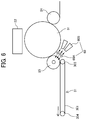
- FIG. 6 is a schematic view of a first dryer in a third embodiment of the present disclosure.
- FIG. 7 is a schematic view of a first dryer in a fourth embodiment of the present disclosure.
- FIG. 8 is a schematic view of a first dryer in a fifth embodiment of the present disclosure.
- FIG. 9 is a schematic view of a second dryer in a sixth embodiment of the present disclosure.
- FIGS. 10A to 10C are illustrative views for illustrating an example of a configuration of transfer between a drum and the transfer cylinder in the printing apparatus.
- FIG. 1 is a schematic illustrative view of a printing apparatus being an apparatus which discharges liquid according to the embodiment
- FIG. 2 is a planar illustrative view of an example of a discharge unit of the printing apparatus.
- a printing apparatus 1 includes with a loader 10 , a printer 20 , a dryer 30 , and an unloader 40 .
- the printing apparatus 1 applies liquid to a sheet material P loaded from the loader 10 and performs required printing thereon by the printer 20 , dries the liquid adhering to the sheet material P by the dryer 30 , and thereafter discharges the sheet material P to the unloader 40 .
- the loader 10 includes a load tray 11 on which a plurality of sheet materials P is stacked, a feeding device 12 which separates the sheet materials P one by one to send from the load tray 11 , and a registration roller pair 13 which feeds the sheet material P to the printer 20 .
- any feeding device such as a device using a roller or a device using air suction may be used.
- the registration roller pair 13 is driven at a predetermined timing to send the sheet material P to the printer 20 .
- the printer 20 includes a sheet conveying device 21 which conveys the sheet material P.
- the sheet conveying device 21 includes a drum 51 which is a supporting member (rotary member) which rotates while supporting the sheet material P on a peripheral surface thereof, and a suction device 52 which is a suction device which generates a suction force on the peripheral surface of the drum 51 .
- the printer 20 also includes a liquid discharger 22 which discharges to apply the liquid to the sheet material P which is carried by the drum 51 of the sheet conveying device 21 to be conveyed.
- the printer 20 also includes a transfer cylinder 24 which receives the fed sheet material P and passes the sheet material P to the drum 51 , and a transfer cylinder 25 which transfers the sheet material P conveyed by the drum 51 to the dryer 30 .
- the sheet material P conveyed from the loader 10 to the printer 20 is gripped at the leading end by a gripper provided on the transfer cylinder 24 and conveyed as the transfer cylinder 24 rotates.
- the sheet material P conveyed by the transfer cylinder 24 is transferred to the drum 51 at a position facing the drum 51 .
- a gripper 81 is provided on a surface of the drum 51 , and the leading end of the sheet material P is gripped by the gripper 81 .
- a plurality of suction holes is dispersedly formed on the surface of the drum 51 .
- the suction device 52 which is the suction device generates a suction airflow inward from a required suction hole of the drum 51 .
- the sheet material P transferred from the transfer cylinder 24 to the drum 51 is gripped at the leading end by the gripper 81 , attracted to be supported on the drum 51 by the suction airflow by the suction device 52 , and conveyed as the drum 51 rotates.
- the liquid discharger 22 includes discharge units 23 ( 23 A to 23 F) being liquid appliers.
- the discharge unit 23 A discharge a cyan (C) liquid
- the discharge unit 23 B discharges a magenta (M) liquid
- the discharge unit 23 C discharges a yellow (Y) liquid
- the discharge unit 23 D discharges a black (K) liquid, respectively.
- the discharge units 23 E and 23 F are used for discharging any one of YMCK liquids or special liquids such as white and gold (silver).
- a discharge unit which discharges a processing liquid such as a surface coating liquid may also be provided.
- the discharge unit 23 is a full line head in which a plurality of liquid discharge heads (hereinafter simply referred to as “heads”) 100 including a nozzle row 101 in which a plurality of nozzles is arranged is arranged on a base member 102 .
- heads liquid discharge heads
- Discharge operation of each discharge unit 23 of the liquid discharger 22 is controlled by a drive signal corresponding to print information.
- the sheet material P supplied on the drum passes through a region facing the liquid discharger 22 , the liquid of each color is discharged from the discharge unit 23 , and an image corresponding to the print information is printed.
- the sheet material P to which the liquid is applied by the liquid discharger 22 is sent from the surface of the drum 51 to the transfer cylinder 25 which is a rotary transfer body.
- a gripper 82 which grips the leading end of the sheet material P is provided, and as the gripper 82 of the transfer cylinder 25 grips the leading end of the sheet material P which has been gripped by the gripper 81 of the drum 51 , the sheet material P is transferred from the surface of the drum 51 to the transfer cylinder 25 .
- the sheet material P is passed to a suction conveyance mechanism 31 of the dryer 30 through a peripheral surface (transfer path) of the transfer cylinder 25 by the rotation of the transfer cylinder 25 .
- a first dryer 60 as a first heater which dries the sheet material P on the transfer path by the transfer cylinder 25 is arranged, and this heats the liquid adhered to the sheet material P in the printer 20 by the first dryer 60 to dry.
- the dryer 30 includes the suction conveyance mechanism 31 which is a conveyor which conveys (sucks to convey) the sheet material P passed from the transfer cylinder 25 of the printer 20 in a sucked state and a drying mechanism 32 which dries the liquid on the sheet material P conveyed by the suction conveyance mechanism 31 .
- the suction conveyance mechanism 31 is a conveyor which conveys (sucks to convey) the sheet material P passed from the transfer cylinder 25 of the printer 20 in a sucked state and a drying mechanism 32 which dries the liquid on the sheet material P conveyed by the suction conveyance mechanism 31 .
- the sheet material P to which the liquid is applied by the printer 20 is dried by the first dryer 60 when this is passed to the suction conveyance mechanism 31 by the transfer cylinder 25 , and is further heated to be dried by the drying mechanism 32 which is a second dryer as a second heater while being conveyed by the suction conveyance mechanism 31 and is transferred to the unloader 40 .
- the liquid on the sheet material P which is dried (pre-dried) by the first dryer 60 is further subjected to a drying process.
- the unloader 40 includes an unload tray 41 on which a plurality of sheet materials P is stacked.
- the sheet material P conveyed from the dryer 30 is sequentially stacked on the unload tray 41 to be held.
- a pre-processor which performs a pre-process on the sheet material P may be arranged on an upstream side of the printer 20 , or a post-processor which performs a post-process on the sheet material P to which the liquid adheres may be arranged between the dryer 30 and the unloader 40 .
- Examples of the pre-processor include, for example, that which performs a pre-coating process in which a treatment liquid which reacts with the liquid to suppress bleeding is applied to the sheet material P.
- Examples of the post-processor include, for example, that which performs a sheet reversing/conveying process for reversing the sheet printed by the printer 20 and sending the same again to the printer 20 to print on both sides of the sheet material P, and that which performs a process of binding a plurality of sheets.
- the apparatus for discharging liquid may be a printing apparatus that prints on a continuous material such as continuous paper.
- the ink of this embodiment is water-based ink and includes an organic solvent, water, a color material, resin, and an additive.
- organic solvent water, color material, resin, additive, and the like used in the ink are described below.
- the organic solvent used in embodiments of the present disclosure is not limited in particular, and a water-soluble organic solvent may be used.
- a water-soluble organic solvent may be used.
- examples thereof include, for example, polyvalent alcohols, ethers such as polyvalent alcohol alkyl ethers and polyvalent alcohol aryl ethers, nitrogen-containing heterocyclic compounds, amides, amines, and sulfur-containing compounds.
- an organic solvent having a boiling point of 250° C. or lower because this not only serves as a wetting agent but also provides excellent drying properties.
- a content of the organic solvent in the ink is not limited in particular and may be appropriately selected according to the purpose; but is preferably 10% by mass or more and 60% by mass or less and is more preferably 20% by mass or more and 60% by mass or less from the viewpoint of drying property and ejection reliability of the ink.
- a water content in the ink is not limited in particular and may be appropriately selected according to the purpose; but is preferably 10% by mass or more and 90% by mass or less and is more preferably 20% by mass or more and 60% by mass or less from the viewpoint of drying property and ejection reliability of the ink.
- the color material is not limited in particular, and pigments and dyes may be used.
- An inorganic pigment or an organic pigment may be used as the pigments.
- One single type or combination of two or more types may be used.
- a mixed crystal may be used as the pigment.
- a content of the color material in the ink is preferably 0.1% by mass or more and 15% by mass or less and is more preferably 1% by mass or more and 10% by mass or less from the viewpoint of improvement in image density, an excellent fixing property, and ejection stability.
- a black pigment for example, a black pigment, a yellow pigment, a magenta pigment, a cyan pigment, a white pigment, a green pigment, an orange pigment, a glossy pigment such as gold or silver, a metallic pigment and the like may be used.
- a type of resin contained in the ink is not limited in particular and may be appropriately selected according to the purpose; for example, urethane resin, polyester resin, acrylic resin, vinyl acetate resin, styrene resin, butadiene resin, styrene-butadiene resin, vinyl chloride resin, acrylic styrene resin, acrylic silicone resin and the like are included.
- a content of resin is not limited in particular and may be appropriately selected according to the purpose; but is preferably 1% by mass or more and 30% by mass or less and is more preferably 5% by mass or more and 20% by mass or less with respect to an entire ink amount from the viewpoint of fixing property and keeping stability of the ink.
- a surfactant, an antifoaming agent, an antiseptic/antifungal agent, a rust inhibitor, a pH adjuster and the like may also be added to the ink as required.
- FIG. 3 is a perspective illustrative view of the transfer cylinder.
- the transfer cylinder 25 includes a rotating shaft 25 a , flanges 25 b and 25 b attached to both ends of the rotating shaft 25 a , a holding member 84 stretched between the flanges 25 b and 25 b , and a gripper 82 A including a plurality of grippers 82 (refer to FIG. 8 ) held by the holding member 84 and the like.
- the transfer cylinder 25 is generally hollow except for the rotating shaft 25 a , the gripper 82 a , and the holding member 84 , so that hot air and radiant heat may pass through the transfer cylinder 25 in a direction orthogonal to an axial direction.
- FIG. 4 is an illustrative view of a substantial part for illustrating the first dryer and the second dryers.
- an infrared heater (IR heater) 60 A which is a radiant heater is arranged as the first dryer 60 inside the transfer cylinder 25 .
- the suction conveyance mechanism 31 of the dryer 30 includes a suction conveyance belt 301 as a conveyance belt which attracts to convey the sheet material P sent from the drum 51 to be passed from the transfer cylinder 25 , and the suction conveyance belt 301 is stretched between a driving roller 303 and a driven roller 304 , and moves to rotate by drive of the driving roller 303 .
- the drying mechanism 32 of the dryer 30 includes a hot air blower 302 that blows hot air for drying the liquid to the sheet material P conveyed by the suction conveyance belt 301 .
- the second dryer is not limited to the hot air blower 302 , and a radiant heater, for example, an IR heater may also be used.
- a glass fiber mesh belt may be used as the suction conveyance belt 301 .
- the mesh belt it is possible to reduce flapping of the sheet material P due to rebound of the hot air blown from the hot air blower 302 .
- An amount of heat given to the sheet material P by the hot air blower 302 as the second dryer is made larger than the amount of heat applied to the sheet material P by the IR heater 60 A as the first dryer.
- the sheet material P is dried by the IR heater 60 A as the first dryer 60 on the transfer path by the transfer cylinder 25 which transfers the sheet material P from the drum 51 to the suction conveyance belt 301 of the suction conveyance mechanism 31 that is the conveyor.
- the hot air blower 302 of the drying mechanism 32 as the second dryer blows the hot air to the sheet material P dried by the IR heater 60 A to further dry the same.
- the liquid applied to the sheet material P may be surely dried, and a drying property is improved.
- the first dryer 60 dries at an early stage, so that drying unevenness, gloss unevenness, and image unevenness due to movement of the pigments on a printing surface (surface to which the liquid is applied) may be suppressed.
- the second dryer (drying mechanism 32 ) dries, so that reliable fixing may be performed and peeling off from the printing surface may be prevented.
- heat drying by the first dryer 60 and heat drying by the second dryer (drying mechanism 32 ) may be performed.
- UV curable ink if the ink is cured by ultraviolet (UV) irradiation in a position corresponding to the first dryer 60 (the transfer path by the transfer cylinder 25 ), it becomes not necessary to dry in a position of the second dryer.
- UV ultraviolet
- FIG. 5 is an illustrative view of a substantial part for illustrating the first dryer.
- a hot air blower 60 B which blows hot air to a surface on which liquid is applied of a sheet material P from a back surface side of a transfer cylinder 25 is arranged for a transfer path by the transfer cylinder 25 .
- FIG. 6 is an illustrative view of a substantial part for illustrating the first dryer.
- an IR heater 60 A which heats from a side opposite to a surface on which liquid is applied of a sheet material P and a hot air blower 60 B which blows hot air are arranged for a transfer path by a transfer cylinder 25 .
- an amount of heat applied to the sheet material P may be increased from that in the first and second embodiments.
- FIG. 7 is an illustrative view of a substantial part for illustrating the first dryer.
- an IR heater 60 A which heats from a side opposite to a surface on which liquid is applied of a sheet material P is provided for a transfer path by a transfer cylinder 25 , and a guide plate 63 being a guide member is arranged between the transfer cylinder 25 and the IR heater 60 A.
- FIG. 8 is an illustrative view of a substantial part for illustrating the first dryer.
- a transfer cylinder 25 has a smaller diameter (about 1 ⁇ 3 in this embodiment) than a diameter of a drum 51 , and as described above referring to FIG. 3 , in a region in a width direction to hold a sheet material P, a portion other than a gripper 82 , a holding member 84 , and a rotating shaft 25 a is generally hollow.
- the diameter of the transfer cylinder 25 is made a diameter in a circular rotation trajectory of the gripper 82 which holds the sheet material P, or a diameter of the flanges 25 b which support the holding member 84 attached to both ends of the rotating shaft 25 a.
- a hot air blower 60 B which blows hot air to a surface (front surface) on which liquid is applied of the sheet material P from a back surface side of the transfer cylinder 25 is arranged for a transfer path by the transfer cylinder 25 .
- an IR heater 60 A which heats a surface (back surface) opposite to the surface to which the liquid is applied of the sheet material P is arranged for the transfer path by the transfer cylinder 25 .
- the sheet material P may be efficiently dried.
- the sheet material P may be efficiently heated from the front surface and the back surface.
- the transfer cylinder 25 is substantially hollow in a region in a width direction which holds the sheet material P except for the gripper 82 , the holding member 84 , and the rotating shaft 25 a . Therefore, the hot air blown from the hot air blower 60 B may pass through an inside of the transfer cylinder 25 to be blown to the front surface of the sheet material P gripped by the gripper 82 .
- hot air temperature of the hot air blower 60 B is 60 to 100° C.
- the IR heater 60 A uses a heat source having a wavelength of 2 to 3 ⁇ m.
- a blowing direction of the hot air from the hot air blower 60 B is made a direction in which the drum 51 as a rotary member is not warmed, that is, a direction in which this does not face the surface of the rotary member.
- a blowing direction of the hot air from the hot air blower 60 B is made a direction in which the drum 51 as a rotary member is not warmed, that is, a direction in which this does not face the surface of the rotary member.
- FIG. 9 is an illustrative view of a substantial part for illustrating the second dryer.
- a drying mechanism 32 being the second dryer includes hot air blowers 302 and an IR heater 312 arranged between the hot air blowers 302 .
- an amount of heat applied to a sheet material P by the drying mechanism 32 may be made larger than that in the first embodiment.
- the first to sixth embodiments may also be combined with one another.
- FIGS. 10A to 10C is an illustrative view for illustrating the same.
- the drum 51 includes the gripper (claw) 81 which grips the leading end of the sheet material P, and the transfer cylinder 25 also includes the gripper (claw) 82 which grips the leading end of the sheet material P.
- the gripper 81 is held by a holding member 83 arranged inside the drum 51 , and the holding member 83 is rotatably arranged.
- the gripper 82 is held by the holding member 84 arranged inside the transfer cylinder 25 , and the holding member 84 is rotatably arranged.
- the gripper 81 is configured such that a leading end of the gripper 81 approaches the surface of the drum 51 by a mechanism such as a cum at a timing at which the gripper 81 reaches a predetermined position in a rotational direction in conjunction with the rotation of the drum 51 .
- the gripper 82 is configured such that a leading end of the gripper 82 approaches the surface of the transfer cylinder 25 by a mechanism such as a cum at a timing at which the gripper 82 reaches a predetermined position in a rotational direction in conjunction with the rotation of the transfer cylinder 25 .
- transfer (changing) operation by the grippers 81 and 82 is performed such that the sheet material P is conveyed while the leading end of the sheet material P is pressed by the gripper 81 of the drum 51 from the upstream of a transfer section.
- the gripper 82 of the transfer cylinder 25 When approaching the transfer section, the gripper 82 of the transfer cylinder 25 also presses the leading end of the sheet material P as illustrated in FIG. 10B .
- the gripper 82 of the transfer cylinder 25 grips the leading end of the sheet material P which has been gripped by the gripper 81 of the drum 51 , so that the sheet material P is transferred from the drum 51 to the transfer cylinder 25 .
Landscapes
- Health & Medical Sciences (AREA)
- General Health & Medical Sciences (AREA)
- Toxicology (AREA)
- Ink Jet (AREA)
Abstract
Description
Claims (12)
Applications Claiming Priority (6)
| Application Number | Priority Date | Filing Date | Title |
|---|---|---|---|
| JP2019047700 | 2019-03-14 | ||
| JP2019-047700 | 2019-03-14 | ||
| JPJP2019-047700 | 2019-03-14 | ||
| JP2019142664A JP7322578B2 (en) | 2019-03-14 | 2019-08-02 | Device for ejecting liquid |
| JP2019-142664 | 2019-08-02 | ||
| JPJP2019-142664 | 2019-08-02 |
Publications (2)
| Publication Number | Publication Date |
|---|---|
| US20200290371A1 US20200290371A1 (en) | 2020-09-17 |
| US11052679B2 true US11052679B2 (en) | 2021-07-06 |
Family
ID=72422788
Family Applications (1)
| Application Number | Title | Priority Date | Filing Date |
|---|---|---|---|
| US16/815,000 Active US11052679B2 (en) | 2019-03-14 | 2020-03-11 | Apparatus for discharging liquid |
Country Status (1)
| Country | Link |
|---|---|
| US (1) | US11052679B2 (en) |
Families Citing this family (5)
| Publication number | Priority date | Publication date | Assignee | Title |
|---|---|---|---|---|
| US11285737B2 (en) | 2019-12-27 | 2022-03-29 | Ricoh Company, Ltd. | Heater, liquid discharge apparatus, and printer |
| US11559997B2 (en) | 2020-05-29 | 2023-01-24 | Ricoh Company, Ltd. | Heating device, dryer, liquid discharge apparatus, and printer |
| EP3960477B1 (en) | 2020-08-27 | 2024-06-05 | Ricoh Company, Ltd. | Sheet heater, liquid discharge apparatus, and printer |
| DE102020128849A1 (en) * | 2020-11-03 | 2022-06-23 | Value & Intellectual Properties Management Gmbh | Process and arrangement for producing a printed flat packaging material |
| DE102024203234A1 (en) * | 2024-04-09 | 2025-10-09 | Bhs Corrugated Maschinen- Und Anlagenbau Gmbh | Process for drying a printed paper web, drying section |
Citations (11)
| Publication number | Priority date | Publication date | Assignee | Title |
|---|---|---|---|---|
| JP2004142140A (en) | 2002-10-22 | 2004-05-20 | Ricoh Co Ltd | Ink jet recording device and copier |
| JP2012131065A (en) | 2010-12-20 | 2012-07-12 | Fujifilm Corp | Recording medium conveying apparatus and image forming apparatus |
| JP2013047136A (en) | 2011-08-29 | 2013-03-07 | Fujifilm Corp | Recording medium conveyance device and image forming apparatus |
| WO2016190335A1 (en) | 2015-05-26 | 2016-12-01 | コニカミノルタ株式会社 | Inkjet recording device |
| US20170266988A1 (en) | 2016-03-18 | 2017-09-21 | Kohki Asada | Conveying device and printing apparatus |
| US20170266989A1 (en) | 2016-03-18 | 2017-09-21 | Masato Ogawa | Conveying device and printing apparatus |
| US20170266987A1 (en) | 2016-03-18 | 2017-09-21 | Kohki Asada | Conveying device and printing apparatus |
| US20170334218A1 (en) | 2016-05-20 | 2017-11-23 | Masato Ogawa | Conveying device and printing apparatus |
| US20180016106A1 (en) * | 2016-07-15 | 2018-01-18 | Kohki Asada | Conveyance apparatus and printing apparatus |
| US20180147878A1 (en) | 2016-11-26 | 2018-05-31 | Ricoh Company, Ltd. | Drying device and printing apparatus |
| US20180264852A1 (en) | 2017-03-17 | 2018-09-20 | Mitsuo Ohtake | Conveying device, printing apparatus, and drying device |
-
2020
- 2020-03-11 US US16/815,000 patent/US11052679B2/en active Active
Patent Citations (11)
| Publication number | Priority date | Publication date | Assignee | Title |
|---|---|---|---|---|
| JP2004142140A (en) | 2002-10-22 | 2004-05-20 | Ricoh Co Ltd | Ink jet recording device and copier |
| JP2012131065A (en) | 2010-12-20 | 2012-07-12 | Fujifilm Corp | Recording medium conveying apparatus and image forming apparatus |
| JP2013047136A (en) | 2011-08-29 | 2013-03-07 | Fujifilm Corp | Recording medium conveyance device and image forming apparatus |
| WO2016190335A1 (en) | 2015-05-26 | 2016-12-01 | コニカミノルタ株式会社 | Inkjet recording device |
| US20170266988A1 (en) | 2016-03-18 | 2017-09-21 | Kohki Asada | Conveying device and printing apparatus |
| US20170266989A1 (en) | 2016-03-18 | 2017-09-21 | Masato Ogawa | Conveying device and printing apparatus |
| US20170266987A1 (en) | 2016-03-18 | 2017-09-21 | Kohki Asada | Conveying device and printing apparatus |
| US20170334218A1 (en) | 2016-05-20 | 2017-11-23 | Masato Ogawa | Conveying device and printing apparatus |
| US20180016106A1 (en) * | 2016-07-15 | 2018-01-18 | Kohki Asada | Conveyance apparatus and printing apparatus |
| US20180147878A1 (en) | 2016-11-26 | 2018-05-31 | Ricoh Company, Ltd. | Drying device and printing apparatus |
| US20180264852A1 (en) | 2017-03-17 | 2018-09-20 | Mitsuo Ohtake | Conveying device, printing apparatus, and drying device |
Also Published As
| Publication number | Publication date |
|---|---|
| US20200290371A1 (en) | 2020-09-17 |
Similar Documents
| Publication | Publication Date | Title |
|---|---|---|
| US11052679B2 (en) | Apparatus for discharging liquid | |
| US10399362B2 (en) | Conveying device and printing apparatus | |
| US10569570B2 (en) | Conveying device and printing apparatus | |
| US10549567B2 (en) | Drying device and printing apparatus | |
| US10150287B2 (en) | Conveying device and printing apparatus | |
| JP7484488B2 (en) | Heating device, drying device, liquid ejection device | |
| US11890859B2 (en) | Sheet heater, liquid discharge apparatus, and printer | |
| JP7334568B2 (en) | Heating device, liquid ejection device | |
| JP7011793B2 (en) | Transport equipment, drying equipment and image forming equipment | |
| JP7322578B2 (en) | Device for ejecting liquid | |
| US11590772B2 (en) | Heating device, drying device, and liquid discharge apparatus | |
| EP3964464B1 (en) | Sheet conveyor, sheet heater, liquid discharge apparatus, and printer | |
| JP5730487B2 (en) | Blower device and method | |
| JP5351683B2 (en) | Paper discharge unit and printing apparatus | |
| JP7643168B2 (en) | Heating device, drying device, liquid ejection device | |
| JP7155620B2 (en) | Conveying device, device for ejecting liquid | |
| US12351420B2 (en) | Conveyance device, drying device, image forming apparatus, and liquid discharge apparatus | |
| JP2021122948A (en) | Printing conveyance device | |
| US20240391718A1 (en) | Sheet conveyor and image forming apparatus | |
| JP2025142733A (en) | Inkjet recording apparatus and transport control method | |
| JP2024168654A (en) | Sheet stacking device and printing device |
Legal Events
| Date | Code | Title | Description |
|---|---|---|---|
| AS | Assignment |
Owner name: RICOH COMPANY, LTD., JAPAN Free format text: ASSIGNMENT OF ASSIGNORS INTEREST;ASSIGNOR:OGAWA, MASATO;REEL/FRAME:052074/0963 Effective date: 20200302 |
|
| FEPP | Fee payment procedure |
Free format text: ENTITY STATUS SET TO UNDISCOUNTED (ORIGINAL EVENT CODE: BIG.); ENTITY STATUS OF PATENT OWNER: LARGE ENTITY |
|
| STPP | Information on status: patent application and granting procedure in general |
Free format text: DOCKETED NEW CASE - READY FOR EXAMINATION |
|
| STPP | Information on status: patent application and granting procedure in general |
Free format text: NOTICE OF ALLOWANCE MAILED -- APPLICATION RECEIVED IN OFFICE OF PUBLICATIONS |
|
| STPP | Information on status: patent application and granting procedure in general |
Free format text: PUBLICATIONS -- ISSUE FEE PAYMENT RECEIVED |
|
| STPP | Information on status: patent application and granting procedure in general |
Free format text: PUBLICATIONS -- ISSUE FEE PAYMENT VERIFIED |
|
| STCF | Information on status: patent grant |
Free format text: PATENTED CASE |
|
| MAFP | Maintenance fee payment |
Free format text: PAYMENT OF MAINTENANCE FEE, 4TH YEAR, LARGE ENTITY (ORIGINAL EVENT CODE: M1551); ENTITY STATUS OF PATENT OWNER: LARGE ENTITY Year of fee payment: 4 |