US11051492B2 - Buckle structure - Google Patents
Buckle structure Download PDFInfo
- Publication number
- US11051492B2 US11051492B2 US16/705,295 US201916705295A US11051492B2 US 11051492 B2 US11051492 B2 US 11051492B2 US 201916705295 A US201916705295 A US 201916705295A US 11051492 B2 US11051492 B2 US 11051492B2
- Authority
- US
- United States
- Prior art keywords
- question mark
- shaped body
- buckle
- bolt
- movable bolt
- Prior art date
- Legal status (The legal status is an assumption and is not a legal conclusion. Google has not performed a legal analysis and makes no representation as to the accuracy of the status listed.)
- Active
Links
- 230000000903 blocking effect Effects 0.000 claims abstract description 40
- 230000004888 barrier function Effects 0.000 description 4
- 241000282326 Felis catus Species 0.000 description 1
- 206010047531 Visual acuity reduced Diseases 0.000 description 1
- 230000009286 beneficial effect Effects 0.000 description 1
- 230000007812 deficiency Effects 0.000 description 1
- 230000000694 effects Effects 0.000 description 1
- 238000009434 installation Methods 0.000 description 1
- 230000009191 jumping Effects 0.000 description 1
- 239000007788 liquid Substances 0.000 description 1
Images


Classifications
-
- A—HUMAN NECESSITIES
- A01—AGRICULTURE; FORESTRY; ANIMAL HUSBANDRY; HUNTING; TRAPPING; FISHING
- A01K—ANIMAL HUSBANDRY; AVICULTURE; APICULTURE; PISCICULTURE; FISHING; REARING OR BREEDING ANIMALS, NOT OTHERWISE PROVIDED FOR; NEW BREEDS OF ANIMALS
- A01K27/00—Leads or collars, e.g. for dogs
- A01K27/005—Quick-couplings, safety-couplings or shock-absorbing devices between leash and collar
-
- F—MECHANICAL ENGINEERING; LIGHTING; HEATING; WEAPONS; BLASTING
- F16—ENGINEERING ELEMENTS AND UNITS; GENERAL MEASURES FOR PRODUCING AND MAINTAINING EFFECTIVE FUNCTIONING OF MACHINES OR INSTALLATIONS; THERMAL INSULATION IN GENERAL
- F16B—DEVICES FOR FASTENING OR SECURING CONSTRUCTIONAL ELEMENTS OR MACHINE PARTS TOGETHER, e.g. NAILS, BOLTS, CIRCLIPS, CLAMPS, CLIPS OR WEDGES; JOINTS OR JOINTING
- F16B45/00—Hooks; Eyes
- F16B45/02—Hooks with pivoting or elastically bending closing member
- F16B45/023—Hooks with pivoting or elastically bending closing member the closing member pivoting about an axis perpendicular to the plane of the hook
-
- F—MECHANICAL ENGINEERING; LIGHTING; HEATING; WEAPONS; BLASTING
- F16—ENGINEERING ELEMENTS AND UNITS; GENERAL MEASURES FOR PRODUCING AND MAINTAINING EFFECTIVE FUNCTIONING OF MACHINES OR INSTALLATIONS; THERMAL INSULATION IN GENERAL
- F16B—DEVICES FOR FASTENING OR SECURING CONSTRUCTIONAL ELEMENTS OR MACHINE PARTS TOGETHER, e.g. NAILS, BOLTS, CIRCLIPS, CLAMPS, CLIPS OR WEDGES; JOINTS OR JOINTING
- F16B45/00—Hooks; Eyes
- F16B45/02—Hooks with pivoting or elastically bending closing member
- F16B45/024—Hooks with pivoting or elastically bending closing member and having means biasing the closing member about the pivot
- F16B45/026—Hooks with pivoting or elastically bending closing member and having means biasing the closing member about the pivot and including a coil type spring
Definitions
- the present disclosure relates to the field of buckle technology, and in particular to a buckle structure, and more particularly to a buckle structure for connecting a buckle on a pet collar.
- the leash is generally connected to the buckle on the pet collar by means of a buckle to achieve a restriction on the movement of the pet.
- the contact points of the existing buckle for the leash, the movable bolt and the hook-shaped buckle body of the pet are too close to the opening of the hook-shaped buckle body, so that the buckle on the collar is not easy to be installed into the buckle.
- the buckle on the collar is even more difficult to install the buckle, which is very inconvenient to use, especially for the elderly.
- the buckle can be separated from the hook-shaped buckle body and surround the movable bolt, as shown in FIG. 1 and FIG. 2 .
- the buckle on the collar has thrust on the movable bolt, which may directly slide out of the buckle, or the buckle can push the switch of the movable bolt and slide out of the buckle, so there is a risk and probability of slipping out, and potential dangers exist.
- the present disclosure may provide a buckle structure that is convenient to use and safe.
- a buckle structure may include a hook-shaped buckle body and a movable bolt
- the hook-shaped buckle body may include a question mark-shaped body and a blocking section provided at an upper end of the question mark-shaped body, wherein an opening is formed between a lower end of the blocking section and the question mark-shaped body, a lower end of the movable bolt may be hinged at a lower end of the question mark-shaped body, and a reset device is provided between the movable bolt and the question mark-shaped body, and an upper end of the movable bolt is elastically contacted with the upper end of the question mark-shaped body, and a receiving cavity is formed between the movable bolt and the question mark-shaped body, the blocking section may be located outside the receiving cavity.
- the upper end of the blocking section and the upper end of the question mark-shaped body are smoothly transitionally connected, and a middle part of the blocking section is curved toward closely to the direction of the question mark-shaped body.
- the lower end of the blocking section is curved away from the direction of the question mark-shaped body.
- the upper end of the movable bolt is curved toward the upper end of the question mark-shaped body.
- the movable bolt may include a bolt body and a limiting block provided at an upper end of the bolt body, a lower end of the bolt body is hinged with the question mark-shaped body, and the upper end of the bolt body is elastically connected with the question mark-shaped body.
- the limiting block may be connected to a side of the bolt body adjacent to the question mark-shaped body, and the question mark-shaped body correspondingly defines a limiting slot which can accommodate the limiting block.
- the side of the upper end of the bolt body is provided with a handle.
- a part of the handle protrudes from a space surrounded by the question mark-shaped body and the blocking section.
- the lower end of the bolt body is provided with a connecting block
- the connecting block is provided with a first pin hole
- the lower end of the question mark-shaped body is correspondingly provided with a second pin hole
- the movable bolt and the question mark-shaped body are coupled by a pin shaft passing through the first pin hole and the second pin hole, and the movable bolt is rotatable relative to the pin shaft.
- the reset device is a torsion spring sleeved on the pin shaft, one end of the torsion spring abuts the movable bolt, and the other end of the torsion spring abuts the question mark-shaped body.
- the lower end of the question mark-shaped body is provided with a storage slot, and the reset device is placed in the storage slot.
- the hook-shaped buckle body of the buckle structure may include a question mark-shaped body and a blocking section.
- the upper end of the movable bolt is elastically contacted with the upper end of the question mark-shaped body, that is, the contact point of the movable bolt and the hook-shaped buckle body is located at the middle of the hook-shaped buckle body.
- the blocking section is located outside the receiving cavity formed by the movable bolt and the question mark-shaped body, so that when the buckle is installed into the buckle structure, as long as the buckle is sleeved on the blocking section and the buckle is moved toward the receiving cavity, the buckle can be easily installed on the buckle structure, that is, the blocking section can assist the buckle to be introduced into the receiving cavity, which greatly facilitates the introduction and installation of the buckle to the buckle structure.
- the blocking section is located outside the receiving cavity, which can block the buckle from sliding off the hook-shaped buckle body.
- the buckle can not surround the movable bolt, so that no matter how much force is applied to the buckle, the buckle can not push the movable bolt, so that the buckle will not slide out of the buckle structure, which eliminates the risk and probability of the buckle slipping out and is safe to use.
- FIG. 1 is a schematic view showing one of the structures of the prior art in which the buckle slides out of the buckle;
- FIG. 2 is schematic view showing the other one of the structures of the prior art in which the buckle slides out of the buckle;
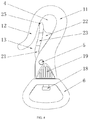
- FIG. 3 is a schematic perspective view according to an embodiment of the present disclosure.
- FIG. 4 is a side view according to an embodiment of the present disclosure.
- FIG. 5 is a schematic structural view of the hook-shaped buckle body according to an embodiment of the present disclosure.
- FIG. 6 is a rear side view according to an embodiment of the present disclosure.
- FIG. 7 is a cross-sectional structural view of the A-A section of FIG. 6 .
- a buckle structure of the present disclosure may include a hook-shaped buckle body 1 and a movable bolt 2 .
- the hook-shaped buckle body 1 may include a question mark-shaped body 11 and a blocking section 12 provided at an upper end of the question mark-shaped body 11 .
- An opening 13 can be formed between the lower end of the blocking section 12 and the question mark-shaped body 11 .
- the lower end of the movable bolt 2 may be hinged at the lower end of the question mark-shaped body 11 , and a reset device 3 is provided between the movable bolt 2 and the question mark-shaped body 11 .
- the upper end of the movable bolt 2 may be elastically contacted with the upper end of the question mark-shaped body 11 , and the receiving cavity 4 can be formed between the movable bolt 2 and the question mark-shaped body 11 , and the blocking section 12 may be located outside the receiving cavity 4 .
- the question mark-shaped body 11 and the blocking section 12 may be of integrated structure, and the question mark-shaped body 11 may include a curved section 111 at its upper end, an inclined section 112 at its middle part, and a vertical section 113 at its lower end.
- Inclined elongated spaces 114 may be formed between the blocking section 12 and the curved section 111 , or formed between the blocking section 12 and the inclined sections 112 .
- the vertical length of the elongated space is larger than the lateral width thereof, and the opening 13 and the receiving cavity 4 may be both part of the elongated space 114 .
- the upper end of the blocking section 12 and the upper end of the question mark-shaped body 11 may be smoothly transitionally connected, and the middle part of the blocking section 12 may be curved toward the direction of the question mark-shaped body 11 , and the lower end of the blocking section 12 may be curved away from the direction of the question mark-shaped body 11 .
- the upper end of the blocking section 12 and the curved section 111 may be smoothly transitionally connected, the middle of the blocking section 12 is curved toward the direction of the inclined section 112 , and the lower end of the blocking section 12 is curved away from the blocking section 112 .
- the middle portion of the blocking section 12 is curved toward the direction of the vertical section 113
- the lower end of the blocking section 12 is curved away from the vertical section 113 .
- the buckle is introduced into the receiving cavity 4 in the direction, the opening 13 is large at the proximal end and small at the distal end, so that the buckle is facilitated to insert into the opening at the proximal end, and then it can reduce the probability of the buckle sliding out of the opening 13 from the receiving cavity 4 at the distal end.
- the lower end of the blocking portion 12 may be curved away from the question mark-shaped body 11 , and the buckle can be better prevented from sliding off the hook-shaped buckle body 1 .
- the upper end of the movable bolt 2 may be curved toward the upper end of the question mark-shaped body 11 to form a barrier section 25 , and one end of the barrier section 25 may be elastically contacted with the curved section 111 , and the barrier section 25 and the curved section 111 are mutually perpendicular to each other at the contact point.
- the movable bolt 2 may include a bolt body 21 and a limiting block 22 provided at an upper end of the bolt body 21 .
- the lower end of the bolt body 21 may be hinged with the question mark-shaped body 11 , and the upper end of the bolt body 21 is the barrier section 25 designed such that when the buckle is applied with force toward the movable bolt 2 from the contact position of the movable bolt 2 and the hook-shaped buckle body 1 in the receiving cavity 4 , the direction of the thrust is always directed toward the near direction pushing the movable bolt 2 toward the hook-shaped buckle body 1 . That is, the direction of the thrust is directed toward the locking direction of the movable bolt 2 , the buckle can not extrude the movable bolt 2 , which can effectively prevent the buckle from disengaging the buckle structure.
- the limiting block 22 may be connected to the side of the bolt body 21 adjacent to the question mark-shaped body 11 .
- the limiting block 22 is connected to the bolt body 21 at the side adjacent to the inclined section 112 .
- a limiting slot 14 is defined in the inclined section 112 , and the limiting slot 14 can accommodate the limiting block 22 .
- the limiting block 22 may be an inverted triangle, and the upper end surface of the inverted triangle is smoothly connected with the bolt body 21 , the limiting slot 14 may be a cubic shape, and the notch of the limiting slot 14 may face the elongated space 114 .
- a handle 23 may be provided on the side of the upper end of the bolt body 21 .
- a part of the handle 23 may protrude from the space surrounded by the question mark-shaped body 11 and the blocking section 12 .
- Both the handle 23 and the portion of the bolt body 21 provided with the handle 23 are curved in a direction close to the inclined section 112 , making the finger more comfortable when the handle 23 is pressed.
- the lower end of the bolt body 21 may be provided with a connecting block 24 which is provided with a first pin hole.
- the connecting block 24 is formed as part in a circular shape, and the first pin hole is provided at the center of the circle.
- the lower end of the question mark-shaped body 11 is correspondingly provided with a second pin hole 16 , and the movable bolt 2 and the question mark-shaped body 11 are connected by the pin shaft 5 passing through the first pin hole and the second pin hole 16 , and the movable bolt 2 can be rotated relative to the pin shaft 5 .
- the vertical section 113 may be provided with a storage slot 15 , the notch of the storage slot 15 may face the elongated space 114 , the storage slot 15 communicates with the limiting slot 14 .
- the connecting block 24 and the lower part of the bolt body 21 are located in the storage slot 15 , the pin 5 may pass through the storage slot 15 .
- the reset device 3 may be a torsion spring, and the torsion spring may be located in the storage slot 15 .
- the torsion spring may be sleeved on the pin shaft 5 , and one end of the torsion spring abuts the movable bolt 2 , and the other end of the torsion spring abuts the vertical section 113 .
- the restoring force of the torsion spring may cause the upper end of the movable bolt 2 to rotate in the direction of the blocking section 12 to seal the receiving cavity 4 , and the lower portion of the bolt body 21 may block the notch of the storage slot 15 .
- the lower side surface of the storage tank 15 may be an inclined surface 151 forming an obtuse angle with the bottom of the storage slot 15 .
- the liquid or small debris falling from the limiting slot 14 into the storage slot 15 can press the handle 23 toward the inclined section 112 , and they may fall from the lower end of the inclined surface 151 .
- the lower side of the bolt body 21 may be also inclined.
- the outer side of the lower end of the question mark-shaped body 11 may be provided with a non-slip pattern 19 , and the non-slip pattern 19 may be a plurality of vertical projections.
- the lower end of the hook-shaped buckle body 1 may be movably connected with an annular body 6 .
- the lower end surface of the hook-shaped buckle body 1 is provided with a cylindrical body 17
- the lower end surface of the cylindrical body is provided with a limiting column 18 .
- the annular body 6 may be provided with a cylindrical hole, and the cylindrical body 17 is bored in the cylindrical hole. The diameter of the cylindrical hole is smaller than that of the limiting column 18 .
Landscapes
- Engineering & Computer Science (AREA)
- General Engineering & Computer Science (AREA)
- Life Sciences & Earth Sciences (AREA)
- Environmental Sciences (AREA)
- Mechanical Engineering (AREA)
- Animal Husbandry (AREA)
- Biodiversity & Conservation Biology (AREA)
- Buckles (AREA)
- Hooks, Suction Cups, And Attachment By Adhesive Means (AREA)
Abstract
Description
Claims (10)
Applications Claiming Priority (2)
| Application Number | Priority Date | Filing Date | Title |
|---|---|---|---|
| CN201911034463.9A CN110622882B (en) | 2019-10-29 | 2019-10-29 | A buckle structure |
| CN201911034463.9 | 2019-10-29 |
Publications (2)
| Publication Number | Publication Date |
|---|---|
| US20210120784A1 US20210120784A1 (en) | 2021-04-29 |
| US11051492B2 true US11051492B2 (en) | 2021-07-06 |
Family
ID=68978008
Family Applications (1)
| Application Number | Title | Priority Date | Filing Date |
|---|---|---|---|
| US16/705,295 Active US11051492B2 (en) | 2019-10-29 | 2019-12-06 | Buckle structure |
Country Status (3)
| Country | Link |
|---|---|
| US (1) | US11051492B2 (en) |
| CN (1) | CN110622882B (en) |
| DE (1) | DE202019106830U1 (en) |
Cited By (1)
| Publication number | Priority date | Publication date | Assignee | Title |
|---|---|---|---|---|
| US20240041176A1 (en) * | 2022-08-04 | 2024-02-08 | Dango Products, Llc | Personal carrying devices |
Families Citing this family (3)
| Publication number | Priority date | Publication date | Assignee | Title |
|---|---|---|---|---|
| KR102915982B1 (en) | 2023-05-11 | 2026-01-21 | 한국전력공사 | Apparatus, system and method of use for electric pole climbing safety clamp |
| US20250237260A1 (en) * | 2024-01-18 | 2025-07-24 | Ying-Chuan Yen | Self-locking hook to avoid unexpected opening |
| USD1103840S1 (en) * | 2024-02-05 | 2025-12-02 | Guangdong Chunteng Industrial Co., Ltd. | Buckle |
Citations (8)
| Publication number | Priority date | Publication date | Assignee | Title |
|---|---|---|---|---|
| US184002A (en) * | 1876-11-07 | Improvement in water-hooks for harness | ||
| US306198A (en) * | 1884-10-07 | Snap-hook | ||
| US403038A (en) * | 1889-05-07 | Snap-hook | ||
| US2978766A (en) * | 1958-06-04 | 1961-04-11 | Charles L Arnett | Safety hook |
| US3831229A (en) * | 1973-02-20 | 1974-08-27 | Stanadyne Inc | Environment free snap hook |
| US5664304A (en) * | 1996-09-06 | 1997-09-09 | Tambornino; Curt | S-hook with safety latch |
| US8434429B2 (en) * | 2008-08-06 | 2013-05-07 | Thomas Andrew Moeller | Pet leash assemblies, pet collar assemblies, and methods of using the same |
| US10233964B2 (en) * | 2016-05-23 | 2019-03-19 | Batz Corporation | Carabiner |
Family Cites Families (6)
| Publication number | Priority date | Publication date | Assignee | Title |
|---|---|---|---|---|
| FR720220A (en) * | 1931-04-30 | 1932-02-17 | Usines Du Paquis Sa Des | Safety device for swivel, lifting or pulling hooks |
| EP1025752A1 (en) * | 1999-01-28 | 2000-08-09 | Hans-Joachim Müller | One-hand operated dog leash |
| JP2015025549A (en) * | 2013-07-29 | 2015-02-05 | 裕見雄 矢鳴 | Swivel |
| TWM506897U (en) * | 2015-04-02 | 2015-08-11 | Chung-Wei Wu | Assembled hook |
| CN208030466U (en) * | 2018-03-19 | 2018-11-02 | 佛山市南海金信兴五金制品有限公司 | A kind of dog button |
| CN210929131U (en) * | 2019-10-29 | 2020-07-07 | 东莞市宠爱智能科技有限公司 | Fastener structure |
-
2019
- 2019-10-29 CN CN201911034463.9A patent/CN110622882B/en active Active
- 2019-12-06 US US16/705,295 patent/US11051492B2/en active Active
- 2019-12-09 DE DE202019106830.2U patent/DE202019106830U1/en active Active
Patent Citations (8)
| Publication number | Priority date | Publication date | Assignee | Title |
|---|---|---|---|---|
| US184002A (en) * | 1876-11-07 | Improvement in water-hooks for harness | ||
| US306198A (en) * | 1884-10-07 | Snap-hook | ||
| US403038A (en) * | 1889-05-07 | Snap-hook | ||
| US2978766A (en) * | 1958-06-04 | 1961-04-11 | Charles L Arnett | Safety hook |
| US3831229A (en) * | 1973-02-20 | 1974-08-27 | Stanadyne Inc | Environment free snap hook |
| US5664304A (en) * | 1996-09-06 | 1997-09-09 | Tambornino; Curt | S-hook with safety latch |
| US8434429B2 (en) * | 2008-08-06 | 2013-05-07 | Thomas Andrew Moeller | Pet leash assemblies, pet collar assemblies, and methods of using the same |
| US10233964B2 (en) * | 2016-05-23 | 2019-03-19 | Batz Corporation | Carabiner |
Cited By (1)
| Publication number | Priority date | Publication date | Assignee | Title |
|---|---|---|---|---|
| US20240041176A1 (en) * | 2022-08-04 | 2024-02-08 | Dango Products, Llc | Personal carrying devices |
Also Published As
| Publication number | Publication date |
|---|---|
| CN110622882A (en) | 2019-12-31 |
| US20210120784A1 (en) | 2021-04-29 |
| DE202019106830U1 (en) | 2019-12-19 |
| CN110622882B (en) | 2025-02-11 |
Similar Documents
| Publication | Publication Date | Title |
|---|---|---|
| US11051492B2 (en) | Buckle structure | |
| US5390571A (en) | Push button socket locking mechanism | |
| US7178845B1 (en) | Article grasping device | |
| US8756741B2 (en) | Device with a scraper and a removal head | |
| US6648261B2 (en) | Extendible and retractable lead | |
| KR100287747B1 (en) | Climbing Carabiners for Climbing and Caving | |
| US6453777B1 (en) | Non-metallic three-section extension pole having bulb changer | |
| US20130305582A1 (en) | Quick Detach Sling Swivel | |
| KR100993444B1 (en) | Locking device for insert stem in trolley | |
| US9925961B2 (en) | Device with removal head and lighting element | |
| US6314624B1 (en) | Slide of auto-lock zipper | |
| US4742595A (en) | Window cleaning device | |
| US4733584A (en) | Socket wrench extension | |
| US20040232660A1 (en) | Pushcart with telescopic handle | |
| JPH0237427Y2 (en) | ||
| US6129601A (en) | Pivotable swim fin | |
| US20050204565A1 (en) | Safe knife sheath | |
| US6134719A (en) | Helmet windshield with sunshade device | |
| CA2569808A1 (en) | Snap hook | |
| CN210929131U (en) | Fastener structure | |
| US20030102416A1 (en) | Self-locking pivotal connector combination | |
| ES2215133T3 (en) | INSTRUMENT FOR THE COLLECTION OF ANIMALS. | |
| JPS6351928U (en) | ||
| JP3150382U (en) | Cane with spike bar | |
| EP3207794A1 (en) | Switching device of tractor |
Legal Events
| Date | Code | Title | Description |
|---|---|---|---|
| FEPP | Fee payment procedure |
Free format text: ENTITY STATUS SET TO UNDISCOUNTED (ORIGINAL EVENT CODE: BIG.); ENTITY STATUS OF PATENT OWNER: SMALL ENTITY |
|
| AS | Assignment |
Owner name: DONGGUAN LOVE PETS TECHNOLOGY CO., LTD, CHINA Free format text: ASSIGNMENT OF ASSIGNORS INTEREST;ASSIGNOR:ZHANG, ZHENGZE;REEL/FRAME:051238/0509 Effective date: 20191127 |
|
| FEPP | Fee payment procedure |
Free format text: ENTITY STATUS SET TO SMALL (ORIGINAL EVENT CODE: SMAL); ENTITY STATUS OF PATENT OWNER: SMALL ENTITY |
|
| AS | Assignment |
Owner name: ZHONGSHAN GREAT PETS INTERNATIONAL CO., LTD., CHINA Free format text: ASSIGNMENT OF ASSIGNORS INTEREST;ASSIGNOR:DONGGUAN LOVE PETS TECHNOLOGY CO., LTD;REEL/FRAME:056294/0117 Effective date: 20210512 |
|
| STPP | Information on status: patent application and granting procedure in general |
Free format text: PUBLICATIONS -- ISSUE FEE PAYMENT RECEIVED |
|
| STPP | Information on status: patent application and granting procedure in general |
Free format text: PUBLICATIONS -- ISSUE FEE PAYMENT VERIFIED |
|
| STCF | Information on status: patent grant |
Free format text: PATENTED CASE |
|
| MAFP | Maintenance fee payment |
Free format text: PAYMENT OF MAINTENANCE FEE, 4TH YR, SMALL ENTITY (ORIGINAL EVENT CODE: M2551); ENTITY STATUS OF PATENT OWNER: SMALL ENTITY Year of fee payment: 4 |