US11049252B2 - Moving object tracking apparatus, radiotherapy system and moving object tracking method - Google Patents
Moving object tracking apparatus, radiotherapy system and moving object tracking method Download PDFInfo
- Publication number
- US11049252B2 US11049252B2 US16/703,987 US201916703987A US11049252B2 US 11049252 B2 US11049252 B2 US 11049252B2 US 201916703987 A US201916703987 A US 201916703987A US 11049252 B2 US11049252 B2 US 11049252B2
- Authority
- US
- United States
- Prior art keywords
- fluoroscopic
- image
- target
- value indicating
- moving object
- Prior art date
- Legal status (The legal status is an assumption and is not a legal conclusion. Google has not performed a legal analysis and makes no representation as to the accuracy of the status listed.)
- Active, expires
Links
Images


Classifications
-
- A—HUMAN NECESSITIES
- A61—MEDICAL OR VETERINARY SCIENCE; HYGIENE
- A61N—ELECTROTHERAPY; MAGNETOTHERAPY; RADIATION THERAPY; ULTRASOUND THERAPY
- A61N5/00—Radiation therapy
- A61N5/10—X-ray therapy; Gamma-ray therapy; Particle-irradiation therapy
- A61N5/1048—Monitoring, verifying, controlling systems and methods
- A61N5/1049—Monitoring, verifying, controlling systems and methods for verifying the position of the patient with respect to the radiation beam
-
- A—HUMAN NECESSITIES
- A61—MEDICAL OR VETERINARY SCIENCE; HYGIENE
- A61B—DIAGNOSIS; SURGERY; IDENTIFICATION
- A61B6/00—Apparatus or devices for radiation diagnosis; Apparatus or devices for radiation diagnosis combined with radiation therapy equipment
- A61B6/12—Arrangements for detecting or locating foreign bodies
-
- A—HUMAN NECESSITIES
- A61—MEDICAL OR VETERINARY SCIENCE; HYGIENE
- A61B—DIAGNOSIS; SURGERY; IDENTIFICATION
- A61B6/00—Apparatus or devices for radiation diagnosis; Apparatus or devices for radiation diagnosis combined with radiation therapy equipment
- A61B6/40—Arrangements for generating radiation specially adapted for radiation diagnosis
- A61B6/4007—Arrangements for generating radiation specially adapted for radiation diagnosis characterised by using a plurality of source units
- A61B6/4014—Arrangements for generating radiation specially adapted for radiation diagnosis characterised by using a plurality of source units arranged in multiple source-detector units
-
- A—HUMAN NECESSITIES
- A61—MEDICAL OR VETERINARY SCIENCE; HYGIENE
- A61B—DIAGNOSIS; SURGERY; IDENTIFICATION
- A61B6/00—Apparatus or devices for radiation diagnosis; Apparatus or devices for radiation diagnosis combined with radiation therapy equipment
- A61B6/48—Diagnostic techniques
- A61B6/486—Diagnostic techniques involving generating temporal series of image data
- A61B6/487—Diagnostic techniques involving generating temporal series of image data involving fluoroscopy
-
- A—HUMAN NECESSITIES
- A61—MEDICAL OR VETERINARY SCIENCE; HYGIENE
- A61B—DIAGNOSIS; SURGERY; IDENTIFICATION
- A61B6/00—Apparatus or devices for radiation diagnosis; Apparatus or devices for radiation diagnosis combined with radiation therapy equipment
- A61B6/52—Devices using data or image processing specially adapted for radiation diagnosis
- A61B6/5258—Devices using data or image processing specially adapted for radiation diagnosis involving detection or reduction of artifacts or noise
- A61B6/5264—Devices using data or image processing specially adapted for radiation diagnosis involving detection or reduction of artifacts or noise due to motion
-
- A—HUMAN NECESSITIES
- A61—MEDICAL OR VETERINARY SCIENCE; HYGIENE
- A61B—DIAGNOSIS; SURGERY; IDENTIFICATION
- A61B6/00—Apparatus or devices for radiation diagnosis; Apparatus or devices for radiation diagnosis combined with radiation therapy equipment
- A61B6/54—Control of apparatus or devices for radiation diagnosis
- A61B6/547—Control of apparatus or devices for radiation diagnosis involving tracking of position of the device or parts of the device
-
- G—PHYSICS
- G01—MEASURING; TESTING
- G01N—INVESTIGATING OR ANALYSING MATERIALS BY DETERMINING THEIR CHEMICAL OR PHYSICAL PROPERTIES
- G01N23/00—Investigating or analysing materials by the use of wave or particle radiation, e.g. X-rays or neutrons, not covered by groups G01N3/00 – G01N17/00, G01N21/00 or G01N22/00
- G01N23/02—Investigating or analysing materials by the use of wave or particle radiation, e.g. X-rays or neutrons, not covered by groups G01N3/00 – G01N17/00, G01N21/00 or G01N22/00 by transmitting the radiation through the material
- G01N23/04—Investigating or analysing materials by the use of wave or particle radiation, e.g. X-rays or neutrons, not covered by groups G01N3/00 – G01N17/00, G01N21/00 or G01N22/00 by transmitting the radiation through the material and forming images of the material
- G01N23/043—Investigating or analysing materials by the use of wave or particle radiation, e.g. X-rays or neutrons, not covered by groups G01N3/00 – G01N17/00, G01N21/00 or G01N22/00 by transmitting the radiation through the material and forming images of the material using fluoroscopic examination, with visual observation or video transmission of fluoroscopic images
-
- G—PHYSICS
- G06—COMPUTING OR CALCULATING; COUNTING
- G06T—IMAGE DATA PROCESSING OR GENERATION, IN GENERAL
- G06T5/00—Image enhancement or restoration
- G06T5/10—Image enhancement or restoration using non-spatial domain filtering
-
- G—PHYSICS
- G06—COMPUTING OR CALCULATING; COUNTING
- G06T—IMAGE DATA PROCESSING OR GENERATION, IN GENERAL
- G06T7/00—Image analysis
- G06T7/0002—Inspection of images, e.g. flaw detection
- G06T7/0012—Biomedical image inspection
- G06T7/0014—Biomedical image inspection using an image reference approach
- G06T7/0016—Biomedical image inspection using an image reference approach involving temporal comparison
-
- G—PHYSICS
- G06—COMPUTING OR CALCULATING; COUNTING
- G06T—IMAGE DATA PROCESSING OR GENERATION, IN GENERAL
- G06T7/00—Image analysis
- G06T7/20—Analysis of motion
-
- G—PHYSICS
- G06—COMPUTING OR CALCULATING; COUNTING
- G06T—IMAGE DATA PROCESSING OR GENERATION, IN GENERAL
- G06T7/00—Image analysis
- G06T7/70—Determining position or orientation of objects or cameras
-
- G—PHYSICS
- G06—COMPUTING OR CALCULATING; COUNTING
- G06V—IMAGE OR VIDEO RECOGNITION OR UNDERSTANDING
- G06V10/00—Arrangements for image or video recognition or understanding
- G06V10/70—Arrangements for image or video recognition or understanding using pattern recognition or machine learning
- G06V10/74—Image or video pattern matching; Proximity measures in feature spaces
- G06V10/75—Organisation of the matching processes, e.g. simultaneous or sequential comparisons of image or video features; Coarse-fine approaches, e.g. multi-scale approaches; using context analysis; Selection of dictionaries
- G06V10/751—Comparing pixel values or logical combinations thereof, or feature values having positional relevance, e.g. template matching
-
- A—HUMAN NECESSITIES
- A61—MEDICAL OR VETERINARY SCIENCE; HYGIENE
- A61N—ELECTROTHERAPY; MAGNETOTHERAPY; RADIATION THERAPY; ULTRASOUND THERAPY
- A61N5/00—Radiation therapy
- A61N5/10—X-ray therapy; Gamma-ray therapy; Particle-irradiation therapy
- A61N5/1048—Monitoring, verifying, controlling systems and methods
- A61N5/1049—Monitoring, verifying, controlling systems and methods for verifying the position of the patient with respect to the radiation beam
- A61N2005/1061—Monitoring, verifying, controlling systems and methods for verifying the position of the patient with respect to the radiation beam using an x-ray imaging system having a separate imaging source
-
- A—HUMAN NECESSITIES
- A61—MEDICAL OR VETERINARY SCIENCE; HYGIENE
- A61N—ELECTROTHERAPY; MAGNETOTHERAPY; RADIATION THERAPY; ULTRASOUND THERAPY
- A61N5/00—Radiation therapy
- A61N5/10—X-ray therapy; Gamma-ray therapy; Particle-irradiation therapy
- A61N2005/1085—X-ray therapy; Gamma-ray therapy; Particle-irradiation therapy characterised by the type of particles applied to the patient
- A61N2005/1087—Ions; Protons
-
- A—HUMAN NECESSITIES
- A61—MEDICAL OR VETERINARY SCIENCE; HYGIENE
- A61N—ELECTROTHERAPY; MAGNETOTHERAPY; RADIATION THERAPY; ULTRASOUND THERAPY
- A61N5/00—Radiation therapy
- A61N5/10—X-ray therapy; Gamma-ray therapy; Particle-irradiation therapy
- A61N5/1048—Monitoring, verifying, controlling systems and methods
- A61N5/1064—Monitoring, verifying, controlling systems and methods for adjusting radiation treatment in response to monitoring
- A61N5/1065—Beam adjustment
- A61N5/1067—Beam adjustment in real time, i.e. during treatment
-
- G—PHYSICS
- G06—COMPUTING OR CALCULATING; COUNTING
- G06T—IMAGE DATA PROCESSING OR GENERATION, IN GENERAL
- G06T2207/00—Indexing scheme for image analysis or image enhancement
- G06T2207/10—Image acquisition modality
- G06T2207/10116—X-ray image
- G06T2207/10121—Fluoroscopy
-
- G—PHYSICS
- G06—COMPUTING OR CALCULATING; COUNTING
- G06T—IMAGE DATA PROCESSING OR GENERATION, IN GENERAL
- G06T2207/00—Indexing scheme for image analysis or image enhancement
- G06T2207/30—Subject of image; Context of image processing
- G06T2207/30004—Biomedical image processing
-
- G—PHYSICS
- G06—COMPUTING OR CALCULATING; COUNTING
- G06V—IMAGE OR VIDEO RECOGNITION OR UNDERSTANDING
- G06V2201/00—Indexing scheme relating to image or video recognition or understanding
- G06V2201/07—Target detection
Definitions
- the present invention relates to a moving object tracking apparatus configured to recognize a target position in a subject in real time, a radiotherapy system for irradiating therapeutic radiation using the moving object tracking apparatus, and a moving object tracking method.
- the template image with markers is prepared for template matching on two fluoroscopic images.
- the positions with high matching scores are listed as candidate positions of the marker.
- Each length of common perpendicular lines is calculated with respect to all combinations of two candidate positions of the marker in the list.
- the marker position is detected. Based on the detected marker position, extraction of proton beam to be irradiated to the target is controlled.
- Japanese Unexamined Patent Application Publication No. 2017-124300 discloses the medical image processor that includes a calculation unit and a detection unit.
- the calculation unit sets a first region that includes two or more first pixels around each interest pixel of the fluoroscopic image in the subject, and a second region that includes one or more second pixels different from the two or more first pixels so that the likelihood is calculated.
- the likelihood is the value that becomes large as pixel values of those two or more first pixels approximate to one another, and the pixel values of two or more first pixels and the pixel values of one or more second pixels are separated further. Based on each likelihood value of the interest pixel, the object position in the subject is detected.
- Japanese Unexamined Patent Application Publication No. 2017-196036 discloses the moving object tracking control apparatus is configured to execute the gradation process to pickup images A and B. Using the gradation processed pickup images A and B, the marker position is calculated. The signal for controlling radiation irradiation is generated based on the marker position.
- High accuracy radiotherapy has been required to control the therapeutic radiation irradiation apparatus in accordance with fluctuation in the position and the shape of the affected part owing to motions in the subject body such as respiration and heartbeat.
- the real-time tumor tracking radiotherapy has been known as the method of irradiating the therapeutic radiation with high accuracy.
- the real-time tumor tracking radiotherapy is conducted to locate the target such as the marker detained in the affected part and the patient body in reference to the fluoroscopic image of the inside of the patient body picked up using X-ray and the like.
- the radiation for treatment will be referred to as “therapeutic radiation”, and the radiation for measurement of the target position will be referred to as “fluoroscopic radiation” for distinction therebetween.
- the misrecognition owing to noise may be prevented by the known process disclosed in the documents as described above.
- the marker may be continuously tracked without being missed even in the presence of the marker-like structure near the marker. Upon missing of the marker, the operator does not have to operate the moving object tracking apparatus to redetect the marker.
- the present invention provides a radiotherapy system that includes an irradiation apparatus that generates and irradiates a radiation, two or more paired fluoroscopic apparatuses each including a fluoroscopic radiation detector and a fluoroscopic radiation generator in a pair for picking up a fluoroscopic image of an object to be tracked, a central control section for controlling the irradiation apparatus, and a moving object tracking control section for tracking a position of a moving object by detecting a position of the object to be tracked from the fluoroscopic image picked up by the fluoroscopic apparatuses.
- an irradiation apparatus that generates and irradiates a radiation
- two or more paired fluoroscopic apparatuses each including a fluoroscopic radiation detector and a fluoroscopic radiation generator in a pair for picking up a fluoroscopic image of an object to be tracked
- a central control section for controlling the irradiation apparatus
- a moving object tracking control section for tracking a position of a moving object by detecting a position of the
- the moving object tracking control section executes an emphasizing process to emphasize an image with specific size in each of the fluoroscopic images derived from the two or more paired fluoroscopic apparatuses, obtains a value indicating a certainty degree of detection of a candidate position of the object to be tracked on the image subjected to the emphasizing process, extracts the candidate position based on the value indicating the certainty degree of detection, calculates a value indicating a correlation between the candidate position extracted from images picked up from two or more directions, and a position of the fluoroscopic radiation generator, detects the position of the object to be tracked based on the value indicating the certainty degree of detection, and the value indicating the correlation, and controls irradiation of the radiation to a target based on the detected position of the object to be tracked.
- the object to be tracked in the case of severe fluoroscopic radiation conditions in the presence of excessive noise, the object to be tracked may be accurately detected, and the load to the fluoroscopic radiation detector may be decreased.
- FIG. 1 illustrates an entire structure of a radiotherapy system according to an embodiment of the present invention
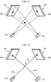
- FIG. 2 is a conceptual view representing that a moving object tracking apparatus according to the embodiment acquires fluoroscopic images
- FIG. 3 is a schematic view representing that the moving object tracking apparatus according to the embodiment calculates a target position from the fluoroscopic images
- FIG. 4 is a schematic view representing the misdetection of noise in the fluoroscopic image
- FIG. 5A is a view showing an example of the fluoroscopic image before application of an emphasizing process by the moving image tracking apparatus of the embodiment
- FIG. 5B is a view showing an example of the fluoroscopic image after application of the emphasizing process by the moving image tracking apparatus of the embodiment
- FIG. 6A is a view showing an example that the fluoroscopic images before application of the emphasizing process are displayed on a console according to the embodiment
- FIG. 6B is a view showing an example that the fluoroscopic images after application of the emphasizing process are displayed on the console according to the embodiment;
- FIG. 7A represents an example of arithmetic results of an evaluation function before application of the emphasizing process according to the embodiment
- FIG. 7B represents an example of the arithmetic results of the evaluation function after application of the emphasizing process according to the embodiment
- FIG. 8A is a conceptual view showing an example of a display of the console according to the embodiment.
- FIG. 8B is a conceptual view showing another example of the display of the console according to the embodiment.
- FIG. 9 is a flowchart of process steps of a real-time tumor tracking radiotherapy.
- FIG. 10 is a conceptual view representing that a moving object tracking apparatus as another example of the embodiment calculates the marker position from the fluoroscopic images.
- a moving object tracking apparatus, a radiotherapy system, and a moving object tracking method according to an embodiment of the present invention will be described referring to FIG. 1 to FIG. 10 .
- FIG. 1 schematically shows an entire structure of the radiotherapy system of the embodiment.
- the radiotherapy system 100 is configured to irradiate a particle beam that contains baryon such as carbon ion, and proton to an affected part (hereinafter referred to as an irradiation target 3 A) in a subject 2 .
- the radiotherapy system 100 includes an accelerator 101 , a beam transporter 102 , a bed 1 that allows positioning of the subject 2 , a therapeutic radiation irradiation apparatus 7 for irradiating the therapeutic particle beam supplied from the accelerator 101 to the irradiation target 3 A in the subject 2 , a therapeutic radiation irradiation controller 103 , a moving object tracking apparatus 104 , a console 106 , and the like.
- a target 3 as the object to be tracked in the subject 2 is described as a marker implanted near the irradiation target 3 A in the subject 2 .
- the therapeutic particle beam is accelerated by the accelerator 101 disposed in the room other than the treatment room to the required energy, and led by the beam transporter 102 to the therapeutic radiation irradiation apparatus 7 .
- the accelerator 101 may be a synchrotron type accelerator, a cyclotron type accelerator, and various types of accelerators.
- the therapeutic radiation irradiation apparatus 7 includes two paired scanning electromagnets, a dose monitor, and a position monitor (all are not shown).
- the two paired scanning electromagnets are disposed in the direction where each pair is orthogonal to each other so that the particle beam is bent to reach the desired position in the plane perpendicular to the beam axis at the target position.
- the dose monitor measures dose of the irradiated particle beam.
- the position monitor is capable of detecting the position through which the particle beam passes. The particle beam that has passed through the therapeutic radiation irradiation apparatus 7 reaches the irradiation target 3 A.
- the particle beam irradiation method is not limited to the particular method. It is possible to use the raster scanning method and the line scanning method for irradiating the fine particle beam without stopping the irradiation besides the spot scanning method in which the dose distributions is formed by arraying dose distribution constituted by fine particle beams adapted to the shape of the irradiation target 3 A.
- the present invention may be applied to the irradiation method for forming the dose distribution adapted to the target shape using the collimator and the bolus after expanding the distribution of the particle beam by, for example, the wobbler method and the double scattered body method.
- a therapeutic X-ray irradiation apparatus for generating therapeutic X-ray is provided instead of the accelerator 101 and the beam transporter 102 .
- a therapeutic ⁇ -ray irradiation apparatus for generating therapeutic ⁇ -ray is provided instead of the accelerator 101 and the beam transporter 102 .
- a therapeutic electron beam irradiation apparatus for generating therapeutic electron beam is provided instead of the accelerator 101 and the beam transporter 102 .
- the moving object tracking apparatus 104 includes fluoroscopic radiographic devices 4 A, 4 B, and a moving object tracking controller 105 .
- the fluoroscopic radiographic device 4 A includes a fluoroscopic radiation generator 5 A for generating the fluoroscopic radiation to the target 3 in the subject 2 from a first direction, a fluoroscopic radiation detector 6 A for detecting a two-dimensional dose distribution of the fluoroscopic radiation that has been generated from the fluoroscopic radiation generator 5 A to permeate through the subject 2 , and a signal processing circuit (not shown).
- the fluoroscopic radiation detector 6 A outputs an analog signal from two-dimensionally arrayed detecting elements.
- the signal processing circuit processes the analog signal from the fluoroscopic radiation detector 6 A to generate data of the fluoroscopic images so that the generated data are transmitted to the moving object tracking controller 105 .
- the fluoroscopic radiographic device 4 B includes a fluoroscopic radiation generator 5 B for generating the fluoroscopic radiation to the target 3 in the subject 2 from a second direction different from the first direction, a fluoroscopic radiation detector 6 B for detecting the two-dimensional dose distribution of the fluoroscopic radiation that has been generated from the fluoroscopic radiation generator 5 B to permeate through the subject 2 , and a signal processing circuit (not shown).
- the fluoroscopic radiation detector 6 B outputs an analog signal from two-dimensionally arrayed detecting elements.
- the signal processing circuit processes the analog signal from the fluoroscopic radiation detector 6 B to generate data of the fluoroscopic images so that the generated data are transmitted to the moving object tracking controller 105 .
- the two fluoroscopic radiation detectors are used.
- the number of the fluoroscopic radiation detectors are not limited so long as the number is two or more.
- the moving object tracking controller 105 executes an arithmetic operation to obtain a position of the target 3 based on signals of the fluoroscopic images input from the fluoroscopic radiographic devices 4 A, 4 B. Based on the position of the target 3 , it is determined whether or not extraction of the therapeutic particle beam is permitted. The signal indicating the determination result on permission of irradiating the therapeutic particle beam is transmitted to the therapeutic radiation irradiation controller 103 .
- the moving object tracking controller 105 irradiates radiation generated from the fluoroscopic radiation generator 5 A to the target 3 as shown in FIG. 2 .
- the fluoroscopic radiation detector 6 A measures the two-dimensional dose distribution of the radiation that has passed through the target 3 so that the image of the target 3 is picked up.
- the radiation generated from the fluoroscopic radiation generator 5 B is irradiated to the target 3 .
- the fluoroscopic radiation detector 6 B measures the two-dimensional dose distribution of the radiation that has passed through the target 3 so that the image of the target 3 is picked up.
- the moving object tracking controller 105 obtains a three-dimensional position of the target 3 from two fluoroscopic images that have been acquired. Based on the result, it is determined whether or not extraction of the therapeutic particle beam is permitted.
- the moving object tracking controller 105 determines whether or not the target 3 is positioned within a preliminarily designated gate range. If it is determined that the target is positioned within the gate range, a gate-on signal is transmitted to the therapeutic radiation irradiation controller 103 to permit extraction of the particle beam to the irradiation target 3 A. If it is determined that the target 3 is not positioned within the gate range, a gate-off signal is transmitted so as not to permit the extraction.
- the moving object tracking controller 105 of the embodiment executes the process for detecting the target 3 .
- the explanation of the process will be made later in detail.
- the fluoroscopic images may be acquired by the fluoroscopic radiographic devices 4 A, 4 B at a constant interval of 30 Hz, for example.
- the target 3 is observed in the acquired fluoroscopic image.
- the process to be described later is executed to identify the position of the target 3 in the fluoroscopic image.
- the position of the target 3 may be searched only in the range in a certain degree of spread from the center, that is, the position of the target 3 in the previous fluoroscopic image.
- FIG. 3 shows a line 31 A formed by connecting a position corresponding to the detected target 3 on the fluoroscopic radiation detector 6 A and the fluoroscopic radiation generator 5 A, and a line 31 B formed by connecting a position corresponding to the target 3 on the fluoroscopic radiation detector 6 B and the fluoroscopic radiation generator 5 B. Ideally, those two lines intersect at one point. The intersection point represents the position of the target 3 .
- the common perpendicular line may be drawn between positions at which those two lines in the twisted relation become proximate to each other.
- a midpoint of the common perpendicular line 32 is set as the three-dimensional position of the target 3 .
- the therapeutic radiation irradiation controller 103 is connected to the accelerator 101 , the beam transporter 102 , and the therapeutic radiation irradiation apparatus 7 , and controls operations of the respective devices constituting the components.
- the therapeutic radiation irradiation controller 103 or the moving object tracking controller 105 may be configured to allow the computer and FPGA (Field-Programmable Gate Array) with a CPU, a memory, an interface and the like to read programs, and to execute the calculation.
- the programs are stored in internal recording media in the respective components, or an external recording medium (not shown). The programs are read and executed by the CPU.
- Operations of the therapeutic radiation irradiation controller 103 or the moving object tracking controller 105 may be controlled by executing the single program.
- the operations may be controlled by executing a plurality of individual programs, or arbitrarily combined programs.
- the program may be partially or entirely executed by the dedicated hardware, or modularized.
- the respective programs may be installed in the respective devices from the program distribution server, the internal storage medium, and the external storage medium.
- the therapeutic radiation irradiation controller 103 or the moving object tracking controller 105 does not have to be formed as the independent component, but may be constituted by integrating and commonizing two or more components each configured to execute the allocated part of the processing. At least a part of the configuration may be wiredly connected, or connected via a wireless network.
- the most essential feature of the embodiment is the processing method of detecting the target 3 using the moving object tracking controller 105 .
- the method will be described referring to FIG. 4 and subsequent drawings.
- one or more candidate positions of the target 3 are detected from the fluoroscopic images acquired by the fluoroscopic radiographic devices 4 A, 4 B so as to obtain the value indicating the certainty degree of candidate detection.
- the value indicating a correlation between the detected candidate positions of the target 3 from the fluoroscopic radiation detectors 6 A, 6 B is obtained. Based on the value indicating the certainty degree of detection and the value indicating the correlation, the three-dimensional position of the target 3 is detected.
- the value indicating the certainty degree of detection may be set as a matching score derived from the template matching.
- a prepared template image of the target 3 is compared with the fluoroscopic image to calculate the degree of similarity to the template image, which is called the matching score.
- the degree of similarity such as a standardized cross correlation may be used as the matching score.
- the position with the matching score higher than the prescribed threshold value is extracted as the candidate position of the target.
- the value indicating the correlation is set as the length of the common perpendicular line (the common perpendicular line 32 as shown in FIG. 3 ).
- the common perpendicular line serves to link two lines by the shortest distance, that is, the line formed by connecting a position corresponding to the candidate position of the target 3 of the fluoroscopic image acquired by the fluoroscopic radiographic device 4 A on the fluoroscopic radiation detector 6 A, and the fluoroscopic radiation generator 5 A, and the line formed by connecting a position corresponding to the candidate position of the target 3 of the fluoroscopic image acquired by the fluoroscopic radiographic device 4 B on the fluoroscopic radiation detector 6 B, and the fluoroscopic radiation generator 5 B.
- a projected image 41 A of the target 3 on the fluoroscopic radiographic device 4 A is buried in noises, and an image 42 with similar structure to that of the target 3 exists near the projected image 41 A of the target 3 . Meanwhile, a projected image 41 B of the target 3 is clearly formed on the fluoroscopic radiographic device 4 B.
- the projected image 41 A of the target 3 on the fluoroscopic radiographic device 4 A is not detected as the candidate position of the target 3 from the template matching.
- the image 42 with the similar structure to that of the target 3 is only detected as the candidate position of the target 3 .
- the length of a common perpendicular line 44 for linking a line 43 A formed by connecting the image 42 and the fluoroscopic radiation generator 5 A, and a line 43 B formed by connecting the image 41 B and the fluoroscopic radiographic generator 5 B takes a large value.
- the image 42 is recognized as the projected image of the target 3 by mistake.
- the intensity of the fluoroscopic radiation is required to be kept high to some extent sufficient to prevent the projected image 41 A of the target 3 from being buried in noises for avoiding the misrecognition.
- the target emphasizing process is applied to emphasize the image with specific size among the fluoroscopic images derived from the two or more paired fluoroscopic radiographic devices 4 A, 4 B for the purpose of further reducing the intensity of the fluoroscopic radiation, and further decreasing the operation load to the fluoroscopic radiation generator.
- the candidate positions of the target are calculated to detect the target position using the value indicating the certainty degree of detection, and the length of the common perpendicular line.
- the process for extracting the specific frequency component from the fluoroscopic image is executed in accordance with the size of the target 3 as an example of the target emphasizing process according to the embodiment.
- one or more filters may be selected from a bandpass filter, a low pass filter, and a high pass filter.
- the parameter of the selected filter is specified in accordance with the size of the target 3 .
- the projected image of the target 3 is formed as an image with its size of approximately 10 pixels in the fluoroscopic image.
- the parameter of the bandpass filter is set to emphasize the image with the size ranging from 5 to 15 pixels.
- the target emphasizing process in the embodiment includes the process of averaging the specific region in accordance with the size of the target 3 in addition to the process of extracting the specific frequency component from the fluoroscopic image.
- one or more filters may be selected from an averaging filter, a median filter, and a Gaussian filter.
- the parameter of the selected filter is specified in accordance with the size of the target 3 .
- the projected image of the target 3 is formed as an image with its size of approximately 10 pixels in the fluoroscopic image.
- the filter size of the averaging filter is set to approximately 3 ⁇ 3 pixels to emphasize the projected image of the target.
- the target emphasizing process allows various types of filters to be combined to provide further advantageous effects.
- the projected image of the target is formed as an image with its size of approximately 10 pixels in the fluoroscopic image.
- a first averaging image and a second averaging image are generated.
- the first averaging image is formed by applying the averaging filter with its size set to 15 ⁇ 15 pixels.
- the second averaging image is formed by applying the averaging filter with its size set to 3 ⁇ 3 pixels. Then the difference between the first and the second averaging images is obtained to execute the process for emphasizing the specific frequency component.
- FIG. 5A shows an example of a fluoroscopic image 51 before applying the target emphasizing process.
- FIG. 5B shows an example of a fluoroscopic image 52 after applying the target emphasizing process.
- the target 3 is a spherical gold marker with diameter of 2 mm, and the bandpass filter is employed for executing the target emphasizing process.
- each projected image of the target 3 is indicated by a white arrow mark, and candidate positions of the target 3 extracted by the template matching are enclosed by black frames.
- the fluoroscopic image 51 before applying the target emphasizing process has the projected image of the originally circular shaped target 3 largely distorted. Therefore, the image is not extracted as the candidate position of the target 3 .
- the fluoroscopic image 52 after applying the target emphasizing process has the projected image of the target 3 similar to the original circular image.
- the matching score becomes high, and such image is extracted as the candidate position.
- Application of the target emphasizing process may lower possibility of failing to extract the projected image of the target 3 as the candidate position.
- FIG. 5B shows, in the fluoroscopic image 52 after applying the target emphasizing process, the images each with similar structure to that of the target 3 are extracted as the candidate positions.
- the length of the common perpendicular line relative to the candidate position of the target 3 derived from the other fluoroscopic radiation detector takes a large value.
- the use of the common perpendicular line distinguishes the projected image of the target 3 from other images.
- the above-described effect allows lowering of possibility of misdetecting the image with the similar structure to that of the target 3 even if the intensity of the fluoroscopic radiation is reduced.
- FIG. 6A shows a fluoroscopic image 61 A derived from the fluoroscopic radiographic device 4 A, and a fluoroscopic image 62 A derived from the fluoroscopic radiographic device 4 B.
- FIG. 6B shows fluoroscopic images 61 B, 62 B after applying the target emphasizing process.
- search areas 63 A, 64 A, 63 B, 64 B in the respective fluoroscopic images There are search areas 63 A, 64 A, 63 B, 64 B in the respective fluoroscopic images.
- points 71 A and 72 A are extracted as the candidate positions of the target 3 in the search area. It is assumed that the point 71 A as a filled circle corresponds to the actual projected image of the target 3 .
- the point 72 A indicates the image that has been incidentally formed by noise to have the similar shape to that of the target 3 .
- a point 73 A is extracted as the candidate position of the target 3 in the search area.
- the projected image of the target 3 is actually formed at the position indicated by a dotted lined circle 74 A, the image is buried in noises on the fluoroscopic image 62 A derived from the fluoroscopic radiographic device 4 B before applying the emphasizing process. Therefore, the point 74 A is not extracted as the candidate position of the target 3 .
- points 71 B, 72 B, 75 B are extracted as the candidate positions of the target 3 in the search area.
- the point 71 B as the filled circle is the actual projected image of the target 3 .
- the point 75 B has not been extracted as the candidate on the fluoroscopic image 61 A.
- the point 75 B is newly extracted on the fluoroscopic image 61 B. Those points are emphasized images of noise with similar structure to that of the target 3 .
- points 73 B, 74 B, 76 B are extracted as candidate positions of the target 3 in the search area.
- the point 74 B as the filled circle is the actual projected image of the target 3 .
- the point 76 B has not been extracted as the candidate on the fluoroscopic image 62 A.
- the point 76 B is newly extracted on the fluoroscopic image 62 B after applying the emphasizing process. Those points are emphasized images of noise with similar structure to that of the target 3 .
- the moving object tracking controller 105 lists the candidate positions of the target 3 extracted from the respective fluoroscopic images. If a group including candidates of the target determined as identical exists in the list prepared from the fluoroscopic images, the candidate with the highest matching score is recognized as the candidate of the target 3 in the group of the list. It is preferable to delete the remaining candidates in the group from the list.
- the candidate with the highest score is selected, and the remaining candidates are deleted from the list. It is possible to preliminarily set the reference range on the console 106 , based on which it is determined that the identical candidates have been selected for deleting the approximating candidates.
- the moving object tracking controller 105 calculates the length of the common perpendicular line with respect to all combinations of the listed candidates.
- S A denotes the score to the fluoroscopic image derived from the fluoroscopic radiographic device 4 A
- S B denotes the score to the fluoroscopic image derived from the fluoroscopic radiographic device 4 B
- L denotes the length of the common perpendicular line.
- Each of w A , w B , w L as a weighting to the corresponding term is set from the console 106 .
- the moving object tracking controller 105 selects the combination having the maximum evaluation function F from all the combinations.
- the midpoint of the common perpendicular line of the selected combination is detected as the position of the target 3 .
- the moving object tracking controller 105 controls the particle beam to be irradiated to the irradiation target 3 A based on the detected position of the target 3 .
- the moving object tracking controller 105 outputs a therapeutic particle beam irradiation signal to the therapeutic radiation irradiation controller 103 for irradiating the particle beam when the object to be tracked is positioned within the preliminarily designated range.
- the therapeutic radiation irradiation controller 103 then controls extraction of the particle beam.
- FIG. 7A shows a list of candidate combinations of the target, which has been prepared from the fluoroscopic images 61 A, 62 A before applying the emphasizing process.
- FIG. 7B shows a list of candidate combinations of the target, which has been prepared from the fluoroscopic images 61 B, 62 B after applying the emphasizing process.
- the projected image of the target 3 is not extracted as the candidate from the fluoroscopic image 62 A. Although the combination with the highest evaluation function F is selected, the point 73 A as the noise is detected by mistake.
- the combination with the highest evaluation function F that is, the combination of the point 71 B of the fluoroscopic image 61 B and the point 74 B of the fluoroscopic image 62 B is selected as the target 3 . This may prevent the misdetection.
- the console 106 is connected to the therapeutic radiation irradiation controller 103 and the moving object tracking controller 105 , and displays the information on the screen based on the signal acquired from the controllers as described above.
- the console 106 receives an input from an operator who operates the radiotherapy system, and transmits various control signals to the therapeutic radiation irradiation controller 103 and the moving object tracking controller 105 .
- the console 106 displays the fluoroscopic images derived from the fluoroscopic radiographic devices 4 A, 4 B, and a tracking condition of the target 3 .
- the parameter required for tracking the target 3 may be set from the console 106 .
- FIG. 8A shows a screen to be displayed on the console 106 for tracking the moving object in association with the moving object tracking controller 105 .
- a fluoroscopic image 81 A derived from the fluoroscopic radiographic device 4 A, and a fluoroscopic image 81 B derived from the fluoroscopic radiographic device 4 B are displayed on the screen of the console 106 .
- a fluoroscopy start button 82 , a set button 83 , and an emphasizing button 84 are displayed at the lower section on the screen. Pressing the emphasizing button 84 as shown in FIG. 8A allows selection between ON and OFF for executing the emphasizing process.
- the screen as shown in FIG. 8B is displayed by pressing the set button 83 of FIG. 8A .
- the screen as shown in FIG. 8B displays a w A input section 85 , a w B input section 86 , and w L input section 87 , respectively for weighting the evaluation function as described above.
- the bed 1 on which the subject 2 is restrained is moved so that the subject 2 is carried to a preliminarily planned position.
- the fluoroscopic images are picked up by the fluoroscopic radiation detectors 6 A, 6 B to confirm that the subject 2 has moved to the preliminarily planned position.
- the moving object tracking controller 105 recognizes that the operator has pressed the fluoroscopy start button 82 on the console 106 (step S 900 ). Subsequent to the confirmation, irradiation of the fluoroscopic radiation is started to allow the fluoroscopic radiographic device 4 A to acquire a fluoroscopic image A, and the fluoroscopic radiographic device 4 B to acquire a fluoroscopic image B (step S 901 A, S 901 B).
- the moving object tracking controller 105 applies the emphasizing process to the acquired fluoroscopic images A and B (steps S 902 A, S 902 B).
- the matching scores to the emphasizing processed fluoroscopic images A, B are calculated by the template matching (steps S 903 A, S 903 B).
- the moving object tracking controller 105 extracts the candidate positions of the target 3 from the fluoroscopic images A and B based on the calculated matching scores (steps S 904 A, S 904 B).
- the moving object tracking controller 105 prepares a combination list based on the extracted candidate positions (step S 905 ) so as to calculate each length of the common perpendicular lines with respect to all the combinations (step S 906 ). Based on the calculated length values of the common perpendicular lines and the matching scores, the moving object tracking controller 105 calculates the three-dimensional position of the target 3 by executing the process as described above (step S 907 ).
- the moving object tracking controller 105 determines whether or not the target 3 is positioned in a gate range (irradiation region) (step S 908 ). If Yes is obtained (the target 3 is positioned in the gate range) in step S 908 , the moving object tracking controller 105 outputs the therapeutic particle beam irradiation signal to the therapeutic radiation irradiation controller 103 , and executes the particle beam extraction control to the therapeutic radiation irradiation apparatus 7 so that the therapeutic particle beam is irradiated to the irradiation target 3 A (step S 909 ).
- step S 908 the moving object tracking controller 105 returns to steps S 901 A, S 901 B.
- the therapeutic radiation irradiation controller 103 determines whether or not a processing end instruction exists (whether there is a specific instruction of the operator, or an instruction to terminate the moving object tracking at the end of therapeutic particle beam irradiation upon termination of the designated irradiation by the therapeutic radiation irradiation apparatus 7 ) (step S 910 ).
- step S 910 the therapeutic radiation irradiation controller 103 stops the fluoroscopic radiographing and the therapeutic particle beam irradiation to terminate the real-time tumor tracking radiotherapy.
- step S 910 the therapeutic radiation irradiation controller 103 returns to steps S 901 A, S 901 B to continue the real-time tumor tracking radiotherapy.
- the radiotherapy system 100 includes the accelerator 101 for generating and irradiating radiation, the beam transporter 102 , the therapeutic radiation irradiation apparatus 7 , two or more paired fluoroscopic radiographic devices 4 A, 4 B having pairs of the fluoroscopic radiation detectors 6 A, 6 B and the fluoroscopic radiation generators 5 A, 5 B, respectively for picking up fluoroscopic images of the target 3 , the therapeutic radiation irradiation controller 103 for controlling the accelerator 101 , the beam transporter 102 , the therapeutic radiation irradiation apparatus 7 , and the moving object tracking controller 105 for tracking the moving object position by detecting the position of the target 3 from the fluoroscopic images picked up by the fluoroscopic radiographic devices 4 A, 4 B.
- the moving object tracking controller 105 emphasizes images each with specific size in the fluoroscopic images acquired by the two or more paired fluoroscopic radiographic devices 4 A, 4 B. Then the value indicating the certainty degree in detecting the candidate positions of the target 3 is obtained in reference to the emphasized images. Based on the certainty degree of detection, the candidates are extracted so as to calculate the value indicating the correlation between the candidate positions extracted from the images picked up from two or more directions, and positions of the fluoroscopic radiation generators 5 A, 5 B, respectively. Based on the value indicating the certainty degree of detection, and the value indicating the correlation, the position of the target 3 is detected. The radiation to be irradiated to the irradiation target 3 A is controlled based on the detected position of the target 3 .
- the moving object tracking apparatus 104 is capable of continuously tracking the target 3 without being missed even in the presence of excessive noise. This makes it possible to reduce the intensity of the fluoroscopic radiation compared with the generally employed system by lowering the possibility of missing the target 3 , and to decrease the operation loads to the fluoroscopic radiation generators 5 A, 5 B compared with the generally employed system.
- Reduction in the intensity of the fluoroscopic radiation may decrease the exposed dosage of the subject 2 .
- the operator does not have to operate the moving object tracking apparatus 104 to redetect the target 3 with high accuracy in the case of missing the target 3 . Therefore, the irradiation time may be reduced.
- the moving object tracking controller 105 determines the size of the image to be emphasized in accordance with the size of the target 3 in the emphasizing process, the target 3 may be emphasized with higher accuracy, thus further lowering the possibility of missing the target 3 .
- the moving object tracking controller 105 extracts the specific frequency component in accordance with the size of the target 3 from the fluoroscopic image to emphasize the image with specific size by using the filter for extracting the specific frequency component from the image, that is, one or more filters selected from the bandpass filter, the low pass filter, and the high pass filter. This may further lower the possibility of missing the target 3 .
- the moving object tracking controller 105 averages the specific region of the fluoroscopic image in accordance with the size of the target 3 to emphasize the image with specific size by using the filter for averaging the specific region, that is, one or more filters selected from the averaging filter, the median filter, and the Gaussian filter. This may further lower the possibility of missing the target 3 .
- the value indicating the correlation is set as the shortest length of the common perpendicular line 32 that connects two or more lines each extending between the candidate position of the target 3 on the fluoroscopic image, and the position of the fluoroscopic radiation generator 5 A or 5 B.
- the target 3 may be misdetected owing to increase in the length of the common perpendicular line.
- the use of the length of the common perpendicular line that indicates the correlation makes it possible to improve accuracy of detecting the target 3 , resulting in reduced frequency of misdetection.
- the moving object tracking controller 105 and the therapeutic radiation irradiation controller 103 irradiate the therapeutic particle beam when the target 3 is positioned in the preliminarily designated range. This makes it possible to improve accuracy of irradiating the particle beam to the irradiation target 3 A.
- the value indicating the certainty degree of detection is set as the matching score derived from the template matching. It is therefore possible to execute the high speed recognizing process, and to search the target 3 while being distinguished from the image similar to the target 3 with respect to the emphasizing processed fluoroscopic images. The possibility of missing the target 3 , thus may further be lowered.
- the moving object tracking controller 105 weights the value indicating the certainty degree of detection, and the value indicating the correlation. Based on the weighting result, the position of the target 3 is detected. It is possible to accurately detect the position of the target 3 even under the severe X-ray image pickup condition, further contributing reduction in the irradiating time.
- the present invention is not limited to the above-described embodiment, but may be variously modified and applied.
- the embodiment has been described for readily understanding of the present invention, and is not limited to the structure provided with all components as described above.
- the embodiment has been described that the matching score and the common perpendicular line are weighted, based on which the position of the target 3 is detected. If a plurality of candidate positions each with higher matching score than the predetermined value are obtained from the respective fluoroscopic images, the plurality of common perpendicular lines are obtained.
- the moving object tracking controller 105 may be configured to detect the candidate position with the matching score corresponding to the shortest common perpendicular line from those obtained as the position of the target 3 .
- the structure as described above reduces the frequency of missing the target 3 . It is therefore possible to decrease the operation loads to the fluoroscopic radiation generators 5 A, 5 B.
- the moving object tracking controller 105 may be configured to set a first region including two or more first pixels around an interest pixel for each of the fluoroscopic images, and a second region including one or more second pixels that are different from the two or more first pixels, and calculate the likelihood that becomes large as values of two or more first pixels approximate to one another, and values of two or more first pixels and the values of one or more second pixels are separated farther. Based on the likelihood, the candidate position is extracted.
- the structure as described above reduces the frequency of missing the target 3 . It is therefore possible to decrease the operation loads to the fluoroscopic radiation generators 5 A, 5 B.
- the length of the common perpendicular line is used as the value indicating the correlation. However, the length of any other element maybe used instead of the common perpendicular line.
- the fluoroscopic images A and B are generated as the axes orthogonal to each other, and those images A and B are projected on the xy plane and the xz plane, respectively.
- a dotted line 28 A indicates a straight line extending from the fluoroscopic radiation generator 5 A while passing through an isocenter 31
- a dotted line 28 B indicates a straight line extending from the fluoroscopic radiation generator 5 B while passing through the isocenter 31
- the dotted line 28 A that connects the positions of the fluoroscopic radiation detector 6 A and the fluoroscopic radiation generator 5 A is orthogonal to the dotted line 28 B that connects the positions of the fluoroscopic radiation detector 6 B and the fluoroscopic radiation generator 5 B.
- the x-axis is a common axis, ideally, the x-coordinates of the target 3 of the images A and B derived from the template matching coincide with each other. Actually, however, the coordinates may be brought into an uncoincident state.
- the difference in the x-coordinate between the images A and B may be used instead of the length of the common perpendicular line.
- the x-axis in this case is referred to as the common axis, and the difference in the x-axis coordinates is referred to as the length of the common axis.
- the use of the length of the common axis as the value indicating the correlation allows reduction in the frequency of missing the target 3 .
- straight lines parallel to those images may be obtained.
- the difference between the straight lines as the common axes may be used instead of the length of the common perpendicular line.
- the spherical target 3 is used.
- the target 3 may have a coiled shape.
- the object to be tracked is not limited to the target 3 .
- the irradiation target 3 A may be directly detected without using the target 3 .
- the object to be tracked may be the high density area in the subject 2 , for example, the bone such as ribs.
- the irradiation method may be the tracking type irradiation for tracking the irradiation position based on the position of the target 3 and the like.
- the direction of the X-ray generator for forming distribution is changed in accordance with movement of the target so that the X-ray irradiation position is changed in accordance with the movement of the target.
- the tracking irradiation may be performed by adjusting the amount of excitation of the scanning electromagnet in alignment with the target position.
- the candidate with the highest matching score is only tracked.
- the candidate positions of the target 3 are listed to include only those derived from the fluoroscopic image where it is difficult to detect the target 3 in the similar way to the generally employed process. Based on the respective matching scores and length values of the common perpendicular lines, the target 3 may be detected.
- the candidates of the target 3 derived from the other fluoroscopic image are narrowed down to one candidate so as to reduce the misdetection while reducing the calculation time.
Landscapes
- Engineering & Computer Science (AREA)
- Health & Medical Sciences (AREA)
- Life Sciences & Earth Sciences (AREA)
- Physics & Mathematics (AREA)
- Medical Informatics (AREA)
- General Health & Medical Sciences (AREA)
- Biomedical Technology (AREA)
- Radiology & Medical Imaging (AREA)
- Nuclear Medicine, Radiotherapy & Molecular Imaging (AREA)
- Pathology (AREA)
- Theoretical Computer Science (AREA)
- Computer Vision & Pattern Recognition (AREA)
- General Physics & Mathematics (AREA)
- Veterinary Medicine (AREA)
- Public Health (AREA)
- Animal Behavior & Ethology (AREA)
- Biophysics (AREA)
- Surgery (AREA)
- Molecular Biology (AREA)
- Heart & Thoracic Surgery (AREA)
- Optics & Photonics (AREA)
- High Energy & Nuclear Physics (AREA)
- Multimedia (AREA)
- Databases & Information Systems (AREA)
- Software Systems (AREA)
- Evolutionary Computation (AREA)
- Computing Systems (AREA)
- Artificial Intelligence (AREA)
- Quality & Reliability (AREA)
- Chemical & Material Sciences (AREA)
- Analytical Chemistry (AREA)
- Biochemistry (AREA)
- Immunology (AREA)
- Radiation-Therapy Devices (AREA)
Abstract
Description
F=w A ×S A W B ×S B +w L×(1/L);
where SA denotes the score to the fluoroscopic image derived from the fluoroscopic
Claims (13)
Applications Claiming Priority (3)
| Application Number | Priority Date | Filing Date | Title |
|---|---|---|---|
| JP2019-126894 | 2019-07-08 | ||
| JP2019126894A JP7252847B2 (en) | 2019-07-08 | 2019-07-08 | Motion tracking device, radiotherapy system, and method of operating motion tracking device |
| JPJP2019-126894 | 2019-07-08 |
Publications (2)
| Publication Number | Publication Date |
|---|---|
| US20210012500A1 US20210012500A1 (en) | 2021-01-14 |
| US11049252B2 true US11049252B2 (en) | 2021-06-29 |
Family
ID=68886781
Family Applications (1)
| Application Number | Title | Priority Date | Filing Date |
|---|---|---|---|
| US16/703,987 Active 2039-12-29 US11049252B2 (en) | 2019-07-08 | 2019-12-05 | Moving object tracking apparatus, radiotherapy system and moving object tracking method |
Country Status (4)
| Country | Link |
|---|---|
| US (1) | US11049252B2 (en) |
| EP (1) | EP3763418B1 (en) |
| JP (1) | JP7252847B2 (en) |
| CN (1) | CN112190838A (en) |
Cited By (2)
| Publication number | Priority date | Publication date | Assignee | Title |
|---|---|---|---|---|
| US20240366963A1 (en) * | 2021-11-08 | 2024-11-07 | Hitachi High-Tech Corporation | Positioning device, radiotherapy device, and positioning method |
| US20240390701A1 (en) * | 2022-02-18 | 2024-11-28 | Hitachi High-Tech Corporation | Positioning device, radiotherapy device, and positioning method |
Families Citing this family (4)
| Publication number | Priority date | Publication date | Assignee | Title |
|---|---|---|---|---|
| JP7093075B2 (en) * | 2018-04-09 | 2022-06-29 | 東芝エネルギーシステムズ株式会社 | Medical image processing equipment, medical image processing methods, and programs |
| JP7711888B2 (en) * | 2021-03-12 | 2025-07-23 | 東芝エネルギーシステムズ株式会社 | Medical image processing device, medical image processing method, medical image processing program, and radiation therapy device |
| US12111148B2 (en) * | 2021-05-21 | 2024-10-08 | General Electric Company | Component imaging systems, apparatus, and methods |
| CN113368412B (en) * | 2021-06-23 | 2022-07-05 | 沭阳县人民医院 | Special positioner of tumour radiotherapy |
Citations (20)
| Publication number | Priority date | Publication date | Assignee | Title |
|---|---|---|---|---|
| US6307914B1 (en) * | 1998-03-12 | 2001-10-23 | Mitsubishi Denki Kabushiki Kaisha | Moving body pursuit irradiating device and positioning method using this device |
| US20070211857A1 (en) * | 2006-03-10 | 2007-09-13 | Susumu Urano | Radiotherapy device control apparatus and radiation irradiation method |
| US20070297566A1 (en) * | 2006-06-23 | 2007-12-27 | Susumu Urano | Radiotherapy device control apparatus and radiation irradiation method |
| US20100316259A1 (en) * | 2009-06-16 | 2010-12-16 | Wu Liu | Using a moving imaging system to monitor anatomical position as a function of time |
| US20110196230A1 (en) * | 2009-11-27 | 2011-08-11 | Shigeru Nishimoto | Radiation therapy apparatus control method and radiation therapy apparatus controller |
| US20120041250A1 (en) * | 2009-02-26 | 2012-02-16 | National University Corporation Hokkaido University | Target tracking device and radiation therapy apparatus |
| US20140018604A1 (en) * | 2011-03-22 | 2014-01-16 | National University Corporation Hokkaido University | Moving object tracking system for radiotherapy |
| WO2014041909A1 (en) | 2012-09-11 | 2014-03-20 | 株式会社日立製作所 | Moving body-tracking device and radiation therapy system |
| US20150036793A1 (en) * | 2013-08-05 | 2015-02-05 | Hitachi, Ltd. | Radiotherapy system |
| JP2017124300A (en) | 2017-04-24 | 2017-07-20 | 株式会社東芝 | Image processing apparatus, therapeutic system and medical image processing method |
| US20170304649A1 (en) * | 2015-07-01 | 2017-10-26 | Kabushiki Kaisha Toshiba | Electric current generating apparatus, control method for electric current generating apparatus, real-time tracking and irradiating system, x-ray irradiating apparatus, and control method for x-ray irradiating apparatus |
| JP2017196036A (en) | 2016-04-26 | 2017-11-02 | 株式会社日立製作所 | Moving body tracking apparatus and radiation irradiation system |
| JP2017209243A (en) | 2016-05-24 | 2017-11-30 | 株式会社日立製作所 | Radiation irradiation system and moving body tracking device |
| US20170348061A1 (en) * | 2012-06-21 | 2017-12-07 | Globus Medical, Inc. | Surgical robot platform |
| US20190060672A1 (en) * | 2017-08-23 | 2019-02-28 | Shimadzu Corporation | Radiotherapy tracking apparatus |
| US20190175941A1 (en) * | 2017-12-07 | 2019-06-13 | Hitachi, Ltd. | Radiation therapy system |
| US20200005472A1 (en) * | 2017-03-03 | 2020-01-02 | University Of Tsukuba | Object tracking device |
| US20200155870A1 (en) * | 2017-06-30 | 2020-05-21 | Shimadzu Corporation | Tracking device for radiation treatment, position detection device, and method for tracking moving body |
| US10737117B2 (en) * | 2017-12-20 | 2020-08-11 | Toshiba Energy Systems & Solutions Corporation | Medical apparatus and method |
| US20210035293A1 (en) * | 2018-04-09 | 2021-02-04 | Toshiba Energy Systems & Solutions Corporation | Medical image processing device, medical image processing method, and storage medium |
Family Cites Families (7)
| Publication number | Priority date | Publication date | Assignee | Title |
|---|---|---|---|---|
| DE60113564T2 (en) * | 2000-12-14 | 2006-07-13 | Matsushita Electric Works, Ltd., Kadoma | Image processing device and pattern recognition device using the image processing device |
| US8363919B2 (en) * | 2009-11-25 | 2013-01-29 | Imaging Sciences International Llc | Marker identification and processing in x-ray images |
| JP2012030005A (en) * | 2010-08-03 | 2012-02-16 | Mitsubishi Heavy Ind Ltd | Radiotherapy equipment controller and radiotherapy equipment control method |
| JP6351017B2 (en) * | 2014-02-24 | 2018-07-04 | 国立研究開発法人量子科学技術研究開発機構 | Radiation therapy moving body tracking device, radiation therapy irradiation region determination device, and radiation therapy device |
| CN105957030B (en) * | 2016-04-26 | 2019-03-22 | 成都市晶林科技有限公司 | One kind being applied to the enhancing of thermal infrared imager image detail and noise suppressing method |
| JP6783547B2 (en) * | 2016-04-28 | 2020-11-11 | キヤノンメディカルシステムズ株式会社 | X-ray diagnostic equipment |
| CN107464229A (en) * | 2017-08-15 | 2017-12-12 | 天津津航技术物理研究所 | A kind of infrared image numerical details Enhancement Method for suppressing noise |
-
2019
- 2019-07-08 JP JP2019126894A patent/JP7252847B2/en active Active
- 2019-12-05 US US16/703,987 patent/US11049252B2/en active Active
- 2019-12-10 CN CN201911261508.6A patent/CN112190838A/en active Pending
- 2019-12-11 EP EP19215173.6A patent/EP3763418B1/en active Active
Patent Citations (24)
| Publication number | Priority date | Publication date | Assignee | Title |
|---|---|---|---|---|
| US6307914B1 (en) * | 1998-03-12 | 2001-10-23 | Mitsubishi Denki Kabushiki Kaisha | Moving body pursuit irradiating device and positioning method using this device |
| US20070211857A1 (en) * | 2006-03-10 | 2007-09-13 | Susumu Urano | Radiotherapy device control apparatus and radiation irradiation method |
| US20070297566A1 (en) * | 2006-06-23 | 2007-12-27 | Susumu Urano | Radiotherapy device control apparatus and radiation irradiation method |
| US20120041250A1 (en) * | 2009-02-26 | 2012-02-16 | National University Corporation Hokkaido University | Target tracking device and radiation therapy apparatus |
| US20100316259A1 (en) * | 2009-06-16 | 2010-12-16 | Wu Liu | Using a moving imaging system to monitor anatomical position as a function of time |
| US20110196230A1 (en) * | 2009-11-27 | 2011-08-11 | Shigeru Nishimoto | Radiation therapy apparatus control method and radiation therapy apparatus controller |
| US8682414B2 (en) * | 2009-11-27 | 2014-03-25 | Mitsubishi Heavy Industries, Ltd. | Radiation therapy apparatus control method and radiation therapy apparatus controller |
| US20140018604A1 (en) * | 2011-03-22 | 2014-01-16 | National University Corporation Hokkaido University | Moving object tracking system for radiotherapy |
| US20170348061A1 (en) * | 2012-06-21 | 2017-12-07 | Globus Medical, Inc. | Surgical robot platform |
| WO2014041909A1 (en) | 2012-09-11 | 2014-03-20 | 株式会社日立製作所 | Moving body-tracking device and radiation therapy system |
| US20150036793A1 (en) * | 2013-08-05 | 2015-02-05 | Hitachi, Ltd. | Radiotherapy system |
| US9724049B2 (en) * | 2013-08-05 | 2017-08-08 | Hitachi, Ltd. | Radiotherapy system |
| US20170304649A1 (en) * | 2015-07-01 | 2017-10-26 | Kabushiki Kaisha Toshiba | Electric current generating apparatus, control method for electric current generating apparatus, real-time tracking and irradiating system, x-ray irradiating apparatus, and control method for x-ray irradiating apparatus |
| JP2017196036A (en) | 2016-04-26 | 2017-11-02 | 株式会社日立製作所 | Moving body tracking apparatus and radiation irradiation system |
| US20190111282A1 (en) * | 2016-04-26 | 2019-04-18 | Hitachi, Ltd. | Tumor tracking apparatus and irradiation system |
| JP2017209243A (en) | 2016-05-24 | 2017-11-30 | 株式会社日立製作所 | Radiation irradiation system and moving body tracking device |
| US20190143146A1 (en) * | 2016-05-24 | 2019-05-16 | Hitachi, Ltd. | Radiation irradiating system and moving object tracking system |
| US20200005472A1 (en) * | 2017-03-03 | 2020-01-02 | University Of Tsukuba | Object tracking device |
| JP2017124300A (en) | 2017-04-24 | 2017-07-20 | 株式会社東芝 | Image processing apparatus, therapeutic system and medical image processing method |
| US20200155870A1 (en) * | 2017-06-30 | 2020-05-21 | Shimadzu Corporation | Tracking device for radiation treatment, position detection device, and method for tracking moving body |
| US20190060672A1 (en) * | 2017-08-23 | 2019-02-28 | Shimadzu Corporation | Radiotherapy tracking apparatus |
| US20190175941A1 (en) * | 2017-12-07 | 2019-06-13 | Hitachi, Ltd. | Radiation therapy system |
| US10737117B2 (en) * | 2017-12-20 | 2020-08-11 | Toshiba Energy Systems & Solutions Corporation | Medical apparatus and method |
| US20210035293A1 (en) * | 2018-04-09 | 2021-02-04 | Toshiba Energy Systems & Solutions Corporation | Medical image processing device, medical image processing method, and storage medium |
Non-Patent Citations (1)
| Title |
|---|
| Extended European Search Report received in corresponding European Application No. 19215173.6 dated Jun. 9, 2020. |
Cited By (2)
| Publication number | Priority date | Publication date | Assignee | Title |
|---|---|---|---|---|
| US20240366963A1 (en) * | 2021-11-08 | 2024-11-07 | Hitachi High-Tech Corporation | Positioning device, radiotherapy device, and positioning method |
| US20240390701A1 (en) * | 2022-02-18 | 2024-11-28 | Hitachi High-Tech Corporation | Positioning device, radiotherapy device, and positioning method |
Also Published As
| Publication number | Publication date |
|---|---|
| US20210012500A1 (en) | 2021-01-14 |
| CN112190838A (en) | 2021-01-08 |
| EP3763418A1 (en) | 2021-01-13 |
| JP7252847B2 (en) | 2023-04-05 |
| EP3763418B1 (en) | 2023-07-05 |
| JP2021010650A (en) | 2021-02-04 |
Similar Documents
| Publication | Publication Date | Title |
|---|---|---|
| US11049252B2 (en) | Moving object tracking apparatus, radiotherapy system and moving object tracking method | |
| US8121368B2 (en) | 3D real-time tracking of human anatomy using combined kV and MV imaging | |
| KR20200006159A (en) | Medical image processing apparatus, medical image processing method, computer-readable medical-image processing program, moving-object tracking apparatus, and radiation therapy system | |
| JP4126318B2 (en) | Radiotherapy apparatus control apparatus and radiotherapy apparatus control method | |
| JP6742153B2 (en) | Radiation irradiation system and moving body tracking device | |
| US10143431B2 (en) | Medical image processing apparatus and method, and radiotherapeutic apparatus | |
| US10019789B2 (en) | Quality assurance system for radiation therapy equipment, and quality assurance method thereof | |
| EP3565634B1 (en) | System for patient-specific motion management for treatment | |
| KR102187003B1 (en) | Body tracking device and irradiation system | |
| JP5954734B2 (en) | Moving body tracking device and radiation therapy system | |
| EP2821101B1 (en) | Radiotherapy equipment control device, radiotherapy equipment control method, and program executed by computer for radiotherapy equipment | |
| US11090510B2 (en) | Method for tracking tumor location and radiotherapy apparatus | |
| US11282244B2 (en) | Moving body tracking apparatus, radiation therapy system including the same, program, and moving body tracking method | |
| JP2025147689A (en) | Program, moving body tracking device, radiation therapy system, and moving body tracking method | |
| JP2018079010A (en) | X-ray fluoroscopy device and X-ray fluoroscopy method |
Legal Events
| Date | Code | Title | Description |
|---|---|---|---|
| AS | Assignment |
Owner name: HITACHI, LTD., JAPAN Free format text: ASSIGNMENT OF ASSIGNORS INTEREST;ASSIGNORS:MIYAZAKI, KOICHI;UMEKAWA, TORU;FUJII, YUSUKE;REEL/FRAME:051187/0339 Effective date: 20191113 |
|
| FEPP | Fee payment procedure |
Free format text: ENTITY STATUS SET TO UNDISCOUNTED (ORIGINAL EVENT CODE: BIG.); ENTITY STATUS OF PATENT OWNER: LARGE ENTITY |
|
| STPP | Information on status: patent application and granting procedure in general |
Free format text: NOTICE OF ALLOWANCE MAILED -- APPLICATION RECEIVED IN OFFICE OF PUBLICATIONS |
|
| STPP | Information on status: patent application and granting procedure in general |
Free format text: PUBLICATIONS -- ISSUE FEE PAYMENT RECEIVED |
|
| STPP | Information on status: patent application and granting procedure in general |
Free format text: PUBLICATIONS -- ISSUE FEE PAYMENT VERIFIED |
|
| STCF | Information on status: patent grant |
Free format text: PATENTED CASE |
|
| AS | Assignment |
Owner name: HITACHI HIGH-TECH CORPORATION, JAPAN Free format text: ASSIGNMENT OF ASSIGNORS INTEREST;ASSIGNOR:HITACHI, LTD.;REEL/FRAME:068292/0514 Effective date: 20240401 |
|
| MAFP | Maintenance fee payment |
Free format text: PAYMENT OF MAINTENANCE FEE, 4TH YEAR, LARGE ENTITY (ORIGINAL EVENT CODE: M1551); ENTITY STATUS OF PATENT OWNER: LARGE ENTITY Year of fee payment: 4 |