US11047439B2 - Intelligent brake system health monitoring - Google Patents
Intelligent brake system health monitoring Download PDFInfo
- Publication number
- US11047439B2 US11047439B2 US16/255,177 US201916255177A US11047439B2 US 11047439 B2 US11047439 B2 US 11047439B2 US 201916255177 A US201916255177 A US 201916255177A US 11047439 B2 US11047439 B2 US 11047439B2
- Authority
- US
- United States
- Prior art keywords
- brake
- corner
- vehicle
- real
- time
- Prior art date
- Legal status (The legal status is an assumption and is not a legal conclusion. Google has not performed a legal analysis and makes no representation as to the accuracy of the status listed.)
- Active, expires
Links
- 238000012544 monitoring process Methods 0.000 title claims abstract description 17
- 230000036541 health Effects 0.000 title description 8
- 238000000034 method Methods 0.000 claims abstract description 45
- 238000005070 sampling Methods 0.000 claims description 10
- 230000003213 activating effect Effects 0.000 claims 1
- 230000004044 response Effects 0.000 abstract description 43
- 230000010349 pulsation Effects 0.000 abstract description 31
- 238000001816 cooling Methods 0.000 description 54
- 238000004422 calculation algorithm Methods 0.000 description 34
- 238000004364 calculation method Methods 0.000 description 10
- 239000000463 material Substances 0.000 description 10
- 238000005096 rolling process Methods 0.000 description 9
- 230000001133 acceleration Effects 0.000 description 8
- 230000007246 mechanism Effects 0.000 description 8
- 230000005540 biological transmission Effects 0.000 description 7
- 230000002596 correlated effect Effects 0.000 description 7
- 238000013461 design Methods 0.000 description 7
- 238000010586 diagram Methods 0.000 description 7
- 239000012530 fluid Substances 0.000 description 7
- 230000008569 process Effects 0.000 description 7
- 230000006870 function Effects 0.000 description 6
- 238000012546 transfer Methods 0.000 description 6
- 230000008859 change Effects 0.000 description 5
- 238000004590 computer program Methods 0.000 description 5
- 230000002159 abnormal effect Effects 0.000 description 4
- 238000004891 communication Methods 0.000 description 4
- 230000000694 effects Effects 0.000 description 4
- 238000012545 processing Methods 0.000 description 4
- 238000000638 solvent extraction Methods 0.000 description 4
- 230000008901 benefit Effects 0.000 description 3
- 230000003750 conditioning effect Effects 0.000 description 3
- 230000001419 dependent effect Effects 0.000 description 3
- 239000000446 fuel Substances 0.000 description 3
- 230000003287 optical effect Effects 0.000 description 3
- 230000005236 sound signal Effects 0.000 description 3
- 238000012360 testing method Methods 0.000 description 3
- 238000002485 combustion reaction Methods 0.000 description 2
- 230000000875 corresponding effect Effects 0.000 description 2
- 238000001514 detection method Methods 0.000 description 2
- 238000006073 displacement reaction Methods 0.000 description 2
- 239000002783 friction material Substances 0.000 description 2
- 238000005259 measurement Methods 0.000 description 2
- 238000002156 mixing Methods 0.000 description 2
- 230000021715 photosynthesis, light harvesting Effects 0.000 description 2
- 230000000704 physical effect Effects 0.000 description 2
- 230000001172 regenerating effect Effects 0.000 description 2
- 230000009471 action Effects 0.000 description 1
- 238000007796 conventional method Methods 0.000 description 1
- 230000008878 coupling Effects 0.000 description 1
- 238000010168 coupling process Methods 0.000 description 1
- 238000005859 coupling reaction Methods 0.000 description 1
- 238000009429 electrical wiring Methods 0.000 description 1
- 230000005670 electromagnetic radiation Effects 0.000 description 1
- 239000000835 fiber Substances 0.000 description 1
- 230000003116 impacting effect Effects 0.000 description 1
- 238000007689 inspection Methods 0.000 description 1
- 238000012986 modification Methods 0.000 description 1
- 230000004048 modification Effects 0.000 description 1
- 230000003071 parasitic effect Effects 0.000 description 1
- 230000035945 sensitivity Effects 0.000 description 1
- 230000011664 signaling Effects 0.000 description 1
Images


Classifications
-
- B—PERFORMING OPERATIONS; TRANSPORTING
- B60—VEHICLES IN GENERAL
- B60T—VEHICLE BRAKE CONTROL SYSTEMS OR PARTS THEREOF; BRAKE CONTROL SYSTEMS OR PARTS THEREOF, IN GENERAL; ARRANGEMENT OF BRAKING ELEMENTS ON VEHICLES IN GENERAL; PORTABLE DEVICES FOR PREVENTING UNWANTED MOVEMENT OF VEHICLES; VEHICLE MODIFICATIONS TO FACILITATE COOLING OF BRAKES
- B60T17/00—Component parts, details, or accessories of power brake systems not covered by groups B60T8/00, B60T13/00 or B60T15/00, or presenting other characteristic features
- B60T17/18—Safety devices; Monitoring
- B60T17/22—Devices for monitoring or checking brake systems; Signal devices
-
- F—MECHANICAL ENGINEERING; LIGHTING; HEATING; WEAPONS; BLASTING
- F16—ENGINEERING ELEMENTS AND UNITS; GENERAL MEASURES FOR PRODUCING AND MAINTAINING EFFECTIVE FUNCTIONING OF MACHINES OR INSTALLATIONS; THERMAL INSULATION IN GENERAL
- F16D—COUPLINGS FOR TRANSMITTING ROTATION; CLUTCHES; BRAKES
- F16D66/00—Arrangements for monitoring working conditions, e.g. wear, temperature
- F16D2066/001—Temperature
-
- F—MECHANICAL ENGINEERING; LIGHTING; HEATING; WEAPONS; BLASTING
- F16—ENGINEERING ELEMENTS AND UNITS; GENERAL MEASURES FOR PRODUCING AND MAINTAINING EFFECTIVE FUNCTIONING OF MACHINES OR INSTALLATIONS; THERMAL INSULATION IN GENERAL
- F16D—COUPLINGS FOR TRANSMITTING ROTATION; CLUTCHES; BRAKES
- F16D66/00—Arrangements for monitoring working conditions, e.g. wear, temperature
- F16D2066/005—Force, torque, stress or strain
-
- F—MECHANICAL ENGINEERING; LIGHTING; HEATING; WEAPONS; BLASTING
- F16—ENGINEERING ELEMENTS AND UNITS; GENERAL MEASURES FOR PRODUCING AND MAINTAINING EFFECTIVE FUNCTIONING OF MACHINES OR INSTALLATIONS; THERMAL INSULATION IN GENERAL
- F16D—COUPLINGS FOR TRANSMITTING ROTATION; CLUTCHES; BRAKES
- F16D66/00—Arrangements for monitoring working conditions, e.g. wear, temperature
- F16D2066/006—Arrangements for monitoring working conditions, e.g. wear, temperature without direct measurement of the quantity monitored, e.g. wear or temperature calculated form force and duration of braking
-
- F—MECHANICAL ENGINEERING; LIGHTING; HEATING; WEAPONS; BLASTING
- F16—ENGINEERING ELEMENTS AND UNITS; GENERAL MEASURES FOR PRODUCING AND MAINTAINING EFFECTIVE FUNCTIONING OF MACHINES OR INSTALLATIONS; THERMAL INSULATION IN GENERAL
- F16D—COUPLINGS FOR TRANSMITTING ROTATION; CLUTCHES; BRAKES
- F16D55/00—Brakes with substantially-radial braking surfaces pressed together in axial direction, e.g. disc brakes
- F16D55/02—Brakes with substantially-radial braking surfaces pressed together in axial direction, e.g. disc brakes with axially-movable discs or pads pressed against axially-located rotating members
- F16D55/22—Brakes with substantially-radial braking surfaces pressed together in axial direction, e.g. disc brakes with axially-movable discs or pads pressed against axially-located rotating members by clamping an axially-located rotating disc between movable braking members, e.g. movable brake discs or brake pads
- F16D55/224—Brakes with substantially-radial braking surfaces pressed together in axial direction, e.g. disc brakes with axially-movable discs or pads pressed against axially-located rotating members by clamping an axially-located rotating disc between movable braking members, e.g. movable brake discs or brake pads with a common actuating member for the braking members
- F16D55/225—Brakes with substantially-radial braking surfaces pressed together in axial direction, e.g. disc brakes with axially-movable discs or pads pressed against axially-located rotating members by clamping an axially-located rotating disc between movable braking members, e.g. movable brake discs or brake pads with a common actuating member for the braking members the braking members being brake pads
Definitions
- the subject disclosure relates to vehicles, and more particularly relates to methods and systems for monitoring brake corners of a vehicle.
- Brake pad life monitoring has been implemented on vehicles in various ways. Some vehicles have mechanical sensors that provide an audible sound when the brake pad wears sufficiently that the sensor contacts the brake rotor. Some vehicles have an electronic sensor that provides a one-time signal when brake pad wear reaches a predetermined amount of wear, and may indicate this to a vehicle operator as a percentage remaining brake pad life in a vehicle information center accessible on the dash board or steering wheel. A more advanced wear life algorithm estimates brake pad wear based on an estimated rotor temperature correlated with typical driving conditions requiring relatively low braking energy. If the vehicle is self-driving, manual inspection by a human being may not be attainable for a certain period of time.
- a method of monitoring a brake corner of a vehicle includes that real-time brake corner temperature data of the brake corner is detected, real-time brake corner pressure data of the brake corner is detected, and real-time brake corner torque data of the brake corner is detected.
- the method further includes that a brake drag or a brake pulsation is determined in response to the braking energy of the brake corner, whether the brake pedal of the vehicle is applied, and at least one of the real-time brake corner pressure data of the brake corner and the real-time brake corner torque data of the brake corner.
- further embodiments may include that an alert is activated when the brake drag exceeds a brake drag exceedance limit.
- further embodiments may include that the sampling rate of at least one of the real-time brake corner temperature data, the real-time brake corner pressure data, and the real-time brake corner torque data is increased when the brake drag exceeds a brake drag exceedance limit.
- further embodiments may include that an alert is activated when the brake pulsation exceeds a brake pulsation exceedance limit.
- further embodiments may include that the sampling rate of at least one of the real-time brake corner temperature data, the real-time brake corner pressure data, and the real-time brake corner torque data is increased when the brake pulsation exceeds a brake pulsation exceedance limit.
- further embodiments may include that determining the braking energy of the brake corner in response to the real-time brake corner temperature data of the brake corner further includes that the braking energy is determined in response to deceleration parameters of the vehicle. Additionally, determining a braking energy of the brake corner in response to the real-time brake corner temperature data of the brake corner may also include that the braking energy is adjusted in response to aerodynamic losses of the vehicle and the braking energy is adjusted in response to the real-time brake corner temperature data.
- a method of monitoring a brake corner of a vehicle including that real-time brake corner temperature data of the brake corner is detected, real-time brake corner pressure data of the brake corner is detected, and real-time brake corner torque data of the brake corner is detected.
- the method may also include that an estimated brake clamp force is determined in response to at least one of the real-time brake corner temperature data, the real-time brake corner pressure data, and the real-time brake corner torque data.
- further embodiments may include that the brake corner is clamped using the estimated brake clamp force.
- further embodiments may include that after the brake corner has been clamped, the method further includes that the real-time brake corner temperature data of the brake corner is detected, the real-time brake corner pressure data of the brake corner is detected, and the real-time brake corner torque data of the brake corner is detected.
- further embodiments may include that a second estimated brake clamp force is determined in response to at least one of the real-time brake corner temperature data, the real-time brake corner pressure data, and the real-time brake corner torque data when the re-clamp is required.
- the method may further include that the brake corner is re-clamped using the estimated brake clamp force.
- further embodiments may include that determining an estimated brake clamp force in response to at least one of the real-time brake corner temperature data, the real-time brake corner pressure data, and the real-time brake corner torque data further includes that it is determined that a re-clamp is required after a time period in response to the real-time brake corner temperature, the estimated brake clamp force, and cooling coefficients of the brake corner.
- a method of monitoring a brake corner of a vehicle including that real-time brake corner temperature data of the brake corner is detected and real-time brake corner pressure data of the brake corner is detected.
- the method may also include a stiffness of a brake pad of the brake corner in response to at least one of the real-time brake corner temperature data and the real-time brake corner pressure data.
- the method may further include that wear of the brake pad is determined in response to the stiffness of the brake pad.
- further embodiments may include that determining a stiffness of a brake pad of the brake corner in response to at least one of the real-time brake corner temperature data and the real-time brake corner pressure data further includes that braking energy of the brake corner is determined in response to the real-time brake corner temperature data of the brake corner.
- further embodiments may include that determining the braking energy of the brake corner in response to the real-time brake corner temperature data of the brake corner further includes that the braking energy is determined in response to deceleration parameters of the vehicle and braking energy is adjusted in response to aerodynamic losses of the vehicle and the real-time brake corner temperature data.
- further embodiments may include that determining a stiffness of a brake pad of the brake corner in response to at least one of the real-time brake corner temperature data and the real-time brake corner pressure data further includes that the vehicle is determined to be in motion and a stiffness of multiple brake pads of the vehicle is determined when the vehicle is in motion.
- the method may also include that the vehicle is determined to be parked and a stiffness of at least one of the multiple brake pads that is located on an axle of the vehicle having a parking brake is determined when the vehicle is parked.
- the method may further include that the stiffness of the at least one of the multiple brake pads located on the axle of the vehicle having the parking brake is subtracted from the stiffness of multiple brake pads.
- FIG. 1 is a block diagram of a system for monitoring brake corner data, according to an embodiment of the present disclosure
- FIG. 3 is a flow diagram illustrating a method of monitoring brake pads to determine drag of the brake pads and the pulsation rate of the brake pads, according to an embodiment of the present disclosure
- FIG. 4 is a block chart diagram illustrating a second algorithm of determining re-clamp of a parking brake pad, according to an embodiment of the present disclosure
- FIG. 5 is a flow diagram illustrating a method of monitoring brake pads to determine re-clamp of the parking brake pad, according to an embodiment of the present disclosure
- FIG. 7 is a flow diagram illustrating a method of monitoring brake pads to determine the remaining life of the brake pad, according to an embodiment of the present disclosure.
- module refers to processing circuitry that may include an application specific integrated circuit (ASIC), an electronic circuit, a processor (shared, dedicated, or group) and memory that executes one or more software or firmware programs, a combinational logic circuit, and/or other suitable components that provide the described functionality.
- ASIC application specific integrated circuit
- processor shared, dedicated, or group
- memory that executes one or more software or firmware programs, a combinational logic circuit, and/or other suitable components that provide the described functionality.
- Embodiments of the present disclosure may be described herein in terms of functional and/or logical block components and various processing steps. It should be appreciated that such block components may be realized by any number of hardware, software, and/or firmware components configured to perform the specified functions. For example, exemplary embodiments may employ various integrated circuit components, e.g., memory elements, digital signal processing elements, logic elements, look-up tables, or the like, which may carry out a variety of functions under the control of one or more microprocessors or other control devices. In addition, those skilled in the art will appreciate that exemplary embodiments may be practiced in conjunction with any number of control systems, and that the vehicle systems described herein are merely exemplary embodiments.
- a vehicle 10 that has a vehicle body 12 that is operatively connected to rotatable wheels 14 A, 14 B, 14 C, 14 D for moving the vehicle body 12 when propelled by an engine E 1 via a transmission T 1 .
- an engine E 1 e.g., an internal combustion engine
- the embodiments disclosed herein may also be applicable to other vehicles including but not limited to electric vehicles propelled entirely and/or partially by an electric motor.
- the vehicle 10 is a front wheel-drive vehicle.
- Differential D 1 operatively connects the front wheels 14 A, 14 B, and a differential D 2 operatively connects the rear wheels 14 C, 14 D via half shafts as is known.
- Tires 15 are shown mounted on the wheels 14 A, 14 B, 14 C, 14 D.
- the vehicle 10 includes a braking system 16 that is configured to stop rotation of the wheels 14 A, 14 B, 14 C, 14 D.
- the braking system 16 includes a fluid pressure source BP in communication with respective braking mechanism 18 A, 18 B, 18 C, 18 D operatively connected with each respective wheel 14 A, 14 B, 14 C, 14 D.
- the braking mechanisms 18 A, 18 B, 18 C, 18 D each have a brake rotor 20 rotatable with the respective wheel 14 A, 14 B, 14 C, 14 D, and respective brake pads 22 placed in contact with opposite sides of the brake rotor 20 during braking.
- the brake pads 22 and brake rotor 20 form a brake corner 21 .
- Each brake corner 21 includes a sensor 23 configured to measure real-time brake corner pressure, real-time brake corner temperature, and real-time brake corner torque.
- This sensor 23 may exist on the brake pad 22 , or elsewhere within the brake corner 21 .
- the real-time brake corner temperature may be measured between a lining of the brake pad 22 and a back plate of the brake pad 22 .
- the sensor 23 may utilize three separate sensors, such as, for example two piezoelectric sensors to detect a change in voltage to detect real-time brake corner pressure and real-time brake corner torque of the brake pad 22 and one thermocouple sensor to measure real-time brake corner temperature.
- An electronic controller C 1 has a processor 24 that executes a stored algorithm 26 for determining a state of health of the brake corners 21 , including but not limited to a drag of the brake pads 22 , a pulsation rate of the brake corners 21 , an electronic park brake re-clamp requirement, and a remaining life of the brake pad 22 .
- the algorithm 26 may include a first algorithm 26 a for determining drag of the brake corners 21 and the pulsation rate of the brake corners 21 , a second algorithm 26 b for determining re-clamp of a parking brake corner 21 , and a third algorithm 26 c for determining a remaining life of the brake pad 22 .
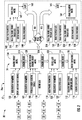
- the system 30 on the vehicle 10 includes various vehicle sensors 32 , and includes the controller C 1 that receives input signals from the sensors 32 so that the processor 24 can carry out the first algorithm 26 a , represented as various modules each modeling aspects of the vehicle operation based on the sensor inputs, to produce an alert 163 , 165 in a brake corner state of health output device 35 , such as an operator display device or an audio signal.
- the controller C 1 that receives input signals from the sensors 32 so that the processor 24 can carry out the first algorithm 26 a , represented as various modules each modeling aspects of the vehicle operation based on the sensor inputs, to produce an alert 163 , 165 in a brake corner state of health output device 35 , such as an operator display device or an audio signal.
- the sensors 32 may include wheel speed sensors, brake fluid pressure sensors, and other sensors and the input from the sensors 32 may include wheel speeds, vehicle speed, longitudinal acceleration, dynamic brake proportioning, brake apply, vehicle grade, brake temperature (brake pad, or brake fluid), brake apply sensor (BAS), steering wheel input, and brake pad life status signal (a voltage reading from a wearout sensor with a resistive circuit). Additionally, the sensor 23 of the brake corner 21 also provides data to the controller C 1 .
- Various systems 34 may provide input signals, including vehicle systems and offboard systems, such as telematics systems, global positioning systems, and map information.
- the controller C 1 can estimate or calculate vehicle mass, road grade, amount of engine braking, braking energy, rolling resistance, appropriate rotor cooling coefficients, lateral and longitudinal acceleration, and other vehicle operating characteristics as described herein.
- the electronic controller C 1 may be configured as a single or a distributed control device that is electrically connected to or otherwise placed in hard-wired or wireless communication with the engine E 1 or electric motors (for BEV/Hybrid), the transmission T 1 , the braking system 16 , and various vehicle components, including sensors, for transmitting and receiving electrical signals for proper execution of the first algorithm 26 a.
- the electronic controller C 1 includes one or more control modules, with one or more processors 24 and tangible, non-transitory memory, e.g., read-only memory (ROM), whether optical, magnetic, flash, or otherwise.
- the electronic controller C 1 may also include sufficient amounts of random access memory (RAM), electrically-erasable programmable read-only memory (EEPROM), and the like, as well as a high-speed clock, analog-to-digital (A/D) and digital-to-analog (D/A) circuitry, and input/output circuitry and devices (I/O), as well as appropriate signal conditioning and buffer circuitry.
- RAM random access memory
- EEPROM electrically-erasable programmable read-only memory
- I/O input/output circuitry and devices
- the electronic controller C 1 can be a host machine or a distributed system, e.g., a computer such as a digital computer or microcomputer, acting as a vehicle control module, and/or as a proportional-integral-derivative (PID) controller device having a processor, and, as the memory, tangible, non-transitory computer-readable memory such as read-only memory (ROM) or flash memory. Therefore, the controller C 1 can include all software, hardware, memory, algorithms, connections, sensors, etc., necessary to monitor the vehicle 10 and control the system 30 . As such, one or more control methods executed by the controller C 1 can be embodied as software or firmware associated with the controller C 1 .
- PID proportional-integral-derivative
- controller C 1 can also include any device capable of analyzing data from various sensors, comparing data, and making decisions required to monitor brake pad wear and alert the vehicle operator of brake pad life.
- electronic controller C 1 can be configured in different embodiments to include a brake controller, a powertrain controller, and other controllers onboard or offboard the vehicle 10 .
- the first algorithm 26 a begins by determining braking energy 114 according to a braking energy model 124 .
- the calculated braking energy 114 used in the rotor temperature model 130 is an estimate of the braking energy dissipation in the braking mechanisms 18 A, 18 B, 18 C, 18 D. This calculation uses various inputs, such as stopping distance, stopping time, brake pad temperature, etc.
- the master cylinder pressure of the braking system 16 , the weight distribution in the vehicle 10 and the dynamic brake proportioning for the proportional brake pressure at each wheel 14 A- 14 D can be used to determine the brake pressure.
- the front and rear brake partitioning 104 is based on where the weight in the vehicle 10 is distributed, and is a known calculation.
- Vehicle mass can be estimated based on engine torque, and is a process well known to those skilled in the art.
- the mass of the vehicle 10 may change as a result of the number of passengers, load in the trunk, fuel capacity, etc. Further, those skilled in the art understand various ways to estimate the road grade in combination with the estimation of the vehicle mass.
- the processor 24 can calculate the braking energy 114 for use in the rotor temperature model 130 by Equation (1) below.
- the braking energy 114 is the work done by the braking mechanisms 18 A- 18 D to decelerate the vehicle 10 , and is the total work minus the rolling resistance, the aerodynamic drag, the engine braking and the road grade.
- the brake work can be used to calculate the power dissipated by the braking mechanisms 18 A, 18 B, 18 C, 18 D, where power equals work per unit of time.
- the power can be calculated at predetermined time intervals during the braking event, for example, every 10 milliseconds.
- Equation (1) M is the mass of the vehicle; E Rolling Resistance is the energy required to roll the vehicle 10 on a flat grade, which is a known value; E Grade is the energy required to roll the vehicle 10 as a result of the grade of the road, which is also a known value; E Engine is the braking provided by the engine E 1 itself, and is also a known value; V 1 is the velocity of the vehicle 10 at the beginning of the braking event; and V F is the velocity of the vehicle 10 at the end of the braking event.
- vehicle 10 deceleration parameters 102 can be used instead of the vehicle speed V, and can be provided by a longitudinal acceleration sensor.
- Braking Torque brake pressure ⁇ area ⁇ (2)
- Braking energy may be an average braking power multiplied by stopping time. Alternately, the braking power can be calculated as:
- the torque is calculated for both the front and the rear of the vehicle 10 and is a function of the brake pressure and the front and rear brake partitioning 104 .
- the Rolling Radius is the rolling radius of the wheel 14 A, 14 B, 14 C, or 14 D, and velocity is the vehicle velocity.
- the processor 24 can then adjust the braking energy 114 for use in the vehicle aero model 132 using the subtractive regen braking energy model 128 .
- the subtractive regen braking energy model 128 adjusts the braking energy 114 in response to motor data 110 , hydraulic regen blending signals 108 , and deceleration parameters 102 .
- the subtractive regen braking energy 128 model is utilized for hybrid or battery electric vehicles due to regenerative braking energy that is generated during a braking event. This energy contributes to the overall stopping energy of the vehicle and is a separate system that has no physical effect on the hardware at the brake corner 21 (i.e., the rotors, calipers, brake pads, etc). Regen braking takes some “load” off of the friction brake corners 21 .
- the subtractive regen braking energy model 128 can be refined with inputs from the regen braking system, to see how much energy should be “subtracted”. If the hydraulic pressure at the brake corner 21 is known, the friction braking energy is directly calculable.
- the vehicle aero model 132 is configured to determine aerodynamic losses in response to aerodynamic parameters 118 , deceleration parameters 120 , and vehicle speed data 122 .
- the vehicle speed data 122 is used to determine the amount of energy dissipated by aerodynamic drag on the vehicle 10 .
- the aerodynamic force on the vehicle 10 is determined as follows:
- Aero ⁇ ⁇ Force ⁇ 1 2 ⁇ C d ⁇ ⁇ ⁇ A ⁇ V 2 ( 4 )
- C d is the aerodynamic drag coefficient
- ⁇ is air density
- A is the vehicle cross sectional area
- V is vehicle velocity.
- the aerodynamic drag coefficient C d , air density ⁇ , and vehicle cross sectional area A may be constants stored in the processor 24 .
- air density ⁇ can be varied according to a sensed air temperature.
- the aerodynamic losses are then subtracted from the braking energy 114 .
- the braking energy 114 can be calculated as change in vehicle kinetic energy minus powertrain losses from the braking energy model 124 and the subtractive regen braking energy model 128 and minus aero effects from the vehicle aero model 132 .
- the resultant braking energy 114 may then be used to calculate the rotor temperature model 130 .
- the first algorithm 26 a determines rotor temperature according to a rotor temperature model 130 .
- the real-time brake corner temperature data 112 is measured at a certain offset from the rotor 20 (e.g., this may be a brake pad lining thickness if measured behind the liner), and as such requires a small thermal calculation to take place in order to determine the true temperature on the rotor 20 . If the sensor 23 is using a thermocouple embedded in the brake pad 22 to detect real-time brake corner temperature data 112 , the detected real-time brake corner temperature data 112 is correlated to the thickness of the lining and the cooling effects between the rotor 20 and brake pad 22 interface, which is subject to speed of vehicle 10 and aero coefficients. Thus, the real-time brake corner temperature data 112 may not be the actual temperature of the rotor 20 , but rather may be less than the actual temperature of the rotor 20 .
- the rotor temperature model 130 utilizes real-time brake corner temperature data 112 and the braking energy 114 determined by the braking energy model 124 and adjusted by the subtractive regen braking energy model 128 and the vehicle aero model 132 .
- the sensor 23 within the brake corner 21 detects in real-time the temperature of the brake corner 21 .
- the rotor temperature model 130 also factors into account a first set of cooling coefficients 116 for a thermal temperature model of the brake pads 22 .
- the calculated braking energy 114 and cooling coefficients 116 are appropriate (i.e., substantially accurate) for vehicle operating conditions with relatively low energy braking, typical of standard driving conditions.
- the first rotor temperature model 130 utilizes a calculated braking energy 114 and an equation for heat transfer from each rotor 20 that utilizes cooling coefficients 116 selected to correlate with the standard driving conditions.
- the cooling rate of the rotors 20 is dependent on the mass of the rotor 20 , vehicle design, vehicle speed, wheel speed, ambient temperature, altitude, etc. As the vehicle 10 moves, the air flowing around each rotor 20 will determine how fast it is cooled from the previous braking event.
- the cooling coefficients 116 used in the lumped capacitance model of temperature decay (Equation 5) are selected to be correlated with relatively standard driving conditions with rotor temperature below a predetermined rotor temperature, vehicle speed below a predetermined vehicle speed, and braking energy below a predetermined braking energy.
- the lumped capacitance model for brake rotor cooling is as follows:
- dT dt - b ⁇ ( T - T a ) + D ⁇ ( 1 ) ( 5 )
- D P d ⁇ ⁇ V c ( 6 )
- P d brake residual drag
- ⁇ the density of the rotor material
- V the volume of the rotor material
- c the specific heat capacity of the rotor material.
- the term b is the “cooling coefficient” and is equal to:
- This information determined by the models 124 , 128 , 132 , 130 is used to help determine trouble zones for drag by the brake drag model 162 and brake pulsation by the brake pulsation model 164 .
- a standard threshold for brake drag may be about 10 Nm, however if high braking energy 114 that would constitute a damaging use case scenario is detected then the first algorithm 26 a could increase the sampling frequency, to quickly capture damage that may have occurred leading to high drag during that event.
- the first algorithm 26 a checks whether the brake pedal is not applied and then moves to either the brake drag model 162 or the brake pulsation model 164 . If the brake pedal is applied at 140 then the first algorithm 26 a moves to the brake drag model 162 .
- the brake drag model 162 determines whether the brake drag is above a trouble threshold 148 in response to brake pad parameters 142 , real-time brake corner torque data 222 , and rotor parameters 146 .
- the brake pad parameters may include, but are not limited to, a coefficient of thermal expansion.
- the coefficient of thermal expansion of the brake pad may indicate that above a specific temperature, the potential for brake drag may increase beyond a trouble threshold 148 , thus sampling of the sensor 23 must increase in frequency or an action taken if a trouble threshold is exceeded.
- the rotor parameters 146 may include, but are not limited to, the coefficient of thermal expansion of the brake rotor 20 .
- the trouble threshold 148 may be a brake drag exceedance limit that activates an alert 163 when exceeded.
- the trouble threshold 148 would be vehicle specific, and based upon the desired goals and performance of the vehicle 10 . For instance, if a given vehicle is sensitive to tactile brake pulsation occurring when brake torque variation exceeds 75 Nm, than the trouble threshold 148 may be set to 75 Nm. A different vehicle may not be sensitive up until 150 Nm.
- a high performance internal combustion engine vehicle may have a higher trouble threshold than a battery electric vehicle.
- the brake drag being above a selected threshold is indicative that the brake pad 22 is unintentionaly impacting the brake rotor 20 .
- the brake drag model 162 is configured to activate an alert 163 if the brake drag is above a selected threshold.
- the alert 163 may be delivered via the brake pad state of health output device 35 .
- the alert 163 may be a message to the driver via an instrument cluster message, center stack message, or telltale indicator light. In the case of autonomous driving the alert 163 may trigger an automatic service check.
- detecting abnormal brake drag may help eliminate parasitic drag on the vehicle 10 , thus improving fuel economy.
- detecting abnormal brake drag may help with early detection of mechanical failure related to specific hardware associated with brake pads 22 , such as, for example, caliper pin, seal, brake wear-out.
- the brake pulsation model 164 determines whether the brake pulsation is above a trouble threshold 158 in response to real-time brake pressure date 224 , brake pad wear data 152 , brake pad parameters 154 , real-time brake corner torque data 222 , rotor parameters 146 , and trouble threshold 158 .
- the brake pad wear data 152 is an output of the linear pad wear model 350 later discussed in relation to FIG. 6 .
- the brake pad parameters may include but are not limited to Young's modulus (i.e., compressibility of the lining), which may in turn impact the sensitivity to pulsation, and the trouble threshold 158 .
- the trouble threshold 158 may be a brake pulsation exceedance limit that activates an alert 165 when exceeded.
- the trouble threshold 158 would be vehicle specific, and based upon the desired goals and performance of the vehicle 10 .
- the brake pulsation being above a selected threshold is indicative that the brake corner 21 is pulsating excessively.
- the brake pulsation model 164 is configured to activate an alert 165 if the brake pulsation is above a selected threshold.
- the alert 165 may be delivered via the brake state of health output device 35 .
- the alert 165 may be a message to the driver via an instrument cluster message, center stack message, or telltale indicator light. In the case of autonomous driving the alert 165 may trigger an automatic service check.
- detecting abnormal brake pulsation could help eliminate tactile pulsation viewed as uncomfortable to the driver or passengers.
- detecting abnormal brake pulsation could help with early detection of mechanical failure related to specific hardware associated with brake components, such as, for example a warped rotor or non-uniformly ground brake pads 22 .
- a flow chart is illustrated of a method 400 of monitoring brake corners 21 of a vehicle 10 , according to an embodiment of the present disclosure.
- the method 400 is performed by the controller C 1 .
- real-time brake corner temperature data 112 of the brake corner 21 is detected.
- real-time brake corner pressure data 224 of the brake corner 21 is detected.
- real-time brake corner torque data 222 of the brake corner 21 is detected.
- braking energy 114 of the brake corner 21 is determined in response to the real-time brake corner temperature data 112 of the brake corner 21 .
- the braking energy 114 of the brake corner 21 may be determined in response to deceleration parameters of the vehicle and then adjusted in response to aerodynamic losses of the vehicle and/or real-time brake corner temperature data 112 .
- a brake drag or a brake pulsation is determined in response to the braking energy 114 of the brake corner 21 , whether the brake pedal of the vehicle 10 is applied and at least one of the real-time brake corner pressure data 224 of the brake corner 21 and the real-time brake corner torque data 222 of the brake corner 21 .
- An alert 163 may be activated when the brake drag exceeds a brake drag exceedance limit.
- the sampling rate may be increased of at least one of the real-time brake corner temperature data 112 , the real-time brake corner pressure data 224 , and the real-time brake corner torque data 222 when the brake drag exceeds a brake drag exceedance limit.
- the sampling rate may be increased of at least one of the real-time brake corner temperature data 112 , the real-time brake corner pressure data 224 , and the real-time brake corner torque data 222 when the brake pulsation exceeds a brake pulsation exceedance limit.
- the system 30 on the vehicle 10 includes various vehicle sensors 32 , and includes the controller C 1 that receives input signals from the sensors 32 so that the processor 24 can carry out the second algorithm 26 b , represented as various modules each modeling aspects of the vehicle operation based on the sensor inputs, to produce an alert in a brake state of health output device 35 , such as an operator display device or an audio signal.
- a brake state of health output device 35 such as an operator display device or an audio signal.
- the sensors 32 may include wheel speed sensors, brake fluid pressure sensors, and other sensors and the input from the sensors 32 may include wheel speeds, vehicle speed, longitudinal acceleration, dynamic brake proportioning, brake apply, vehicle grade, brake temperature (brake pad, or brake fluid), brake apply sensor (BAS), steering wheel input, and brake pad life status signal (a voltage reading from a wearout sensor with a resistive circuit). Additionally, the sensor 23 of the brake corner 21 also provides data to the controller C 1 .
- Various systems 34 may provide input signals, including vehicle systems and offboard systems, such as telematics systems, global positioning systems, and map information.
- the controller C 1 can estimate or calculate vehicle mass, road grade, amount of engine braking, braking energy, rolling resistance, appropriate rotor cooling coefficients, lateral and longitudinal acceleration, and other vehicle operating characteristics as described herein.
- the electronic controller C 1 may be configured as a single or a distributed control device that is electrically connected to or otherwise placed in hard-wired or wireless communication with the engine E 1 or electric motors (for BEV/Hybrid), the transmission T 1 , the braking system 16 , and various vehicle components, including sensors, for transmitting and receiving electrical signals for proper execution of the second algorithm 26 b.
- the electronic controller C 1 includes one or more control modules, with one or more processors 24 and tangible, non-transitory memory, e.g., read-only memory (ROM), whether optical, magnetic, flash, or otherwise.
- the electronic controller C 1 may also include sufficient amounts of random access memory (RAM), electrically-erasable programmable read-only memory (EEPROM), and the like, as well as a high-speed clock, analog-to-digital (A/D) and digital-to-analog (D/A) circuitry, and input/output circuitry and devices (I/O), as well as appropriate signal conditioning and buffer circuitry.
- RAM random access memory
- EEPROM electrically-erasable programmable read-only memory
- I/O input/output circuitry and devices
- controller C 1 can also include any device capable of analyzing data from various sensors, comparing data, and making decisions required to determine whether to re-clamp a parking brake is required.
- electronic controller C 1 can be configured in different embodiments to include a brake controller, a powertrain controller, and other controllers onboard or offboard the vehicle 10 .
- the second algorithm 26 b determines rotor temperature according to a rotor temperature model 130 .
- the real-time brake corner temperature data 112 is measured at a certain offset from the rotor 20 (e.g., this may be a brake pad lining thickness if measured behind the liner), and as such requires a small thermal calculation to take place in order to determine the true temperature on the rotor 20 . If the sensor 23 is using a thermocouple embedded in the brake pad 22 to detect real-time brake corner temperature data 112 , the detected real-time brake corner temperature data 112 is correlated to the thickness of the lining and the cooling effects between the rotor 20 and brake pad 22 interface, which is subject to speed of vehicle 10 and aero coefficients. Thus, the real-time brake corner temperature data 112 may not be the actual temperature of the rotor 20 , but rather may be less than the actual temperature of the rotor 20 .
- the rotor temperature model 130 utilizes real-time brake corner temperature data 112 , ambient temperature 113 , and the braking energy 114 .
- the braking energy 114 may be determined as discussed herein in relation to FIG. 2 .
- the sensor 23 within the brake corner 21 detects in real-time the temperature of the brake corner 21 .
- the rotor temperature model 130 also factors into account a first set of cooling coefficients 116 for a thermal temperature model of the brake corner 21 .
- the calculated braking energy 114 and cooling coefficients 116 are appropriate (i.e., substantially accurate) for vehicle operating conditions with relatively low energy braking, typical of standard driving conditions.
- the first rotor temperature model 130 utilizes a calculated braking energy 114 and an equation for heat transfer from each rotor 20 that utilizes cooling coefficients 116 selected to correlate with the standard driving conditions.
- the cooling rate of the rotors 20 is dependent on the mass of the rotor 20 , vehicle design, vehicle speed, wheel speed, ambient temperature, altitude, etc. As the vehicle 10 moves, the air flowing around each rotor 20 will determine how fast it is cooled from the previous braking event.
- the cooling coefficients 116 used in the lumped capacitance model of temperature decay (Equation 9) are selected to be correlated with relatively standard driving conditions with rotor temperature below a predetermined rotor temperature, vehicle speed below a predetermined vehicle speed, and braking energy below a predetermined braking energy.
- the lumped capacitance model for brake rotor cooling is as follows:
- the brake apply model 210 is configured to determine a force to apply the parking brake in response to vehicle grade data 212 , current feedback 214 , estimated brake clamp force 216 , real-time brake corner torque data 222 , and real-time brake corner pressure data 224 .
- the estimated brake clamp force 216 may be a real time output of the real-time brake corner pressure data 224 .
- the current feedback 214 is an electrical motor current for a motor-on-caliper park brake actuator. The data is consumed to determine estimated brake clamp force 216 currently, and this estimated brake clamp force 216 is refined with real time clamp data.
- the brake apply model 210 is the combined algorithm, which will look at motor current data, temperature data, vehicle grade data and real time clamp force data to determine the appropriate threshold to provide a park brake reapply, if needed.
- the brake apply model 210 may determine that a re-clamp is required after a time period in response to the real-time brake corner temperature 112 , the estimated brake clamp force 216 , and cooling coefficients 116 of the brake corner 21 .
- a flow chart is illustrated of a method 500 of monitoring brake corners 21 of a vehicle 10 , according to an embodiment of the present disclosure.
- the method 500 is performed by the controller C 1 .
- the method 500 may also include that the brake corner 21 is clamped using the estimated brake clamp force 216 .
- real-time brake corner temperature data 112 of the brake corner 21 real-time brake corner pressure data 224 of the brake corner 21 , and real-time brake corner torque data 222 of the brake corner 21 may be continuously detected.
- it may be determined whether a re-clamp is required in response to at least one of the real-time brake corner temperature data 112 , the real-time brake corner pressure data 224 , and the real-time brake corner torque data 222 .
- the method 500 may further include that a re-clamp may be determined to be required after a time period in response to the real-time brake corner temperature 112 , the estimated brake clamp force 216 , and cooling coefficients 116 of the brake corner 21 .
- the sensors 32 may include wheel speed sensors, brake fluid pressure sensors, and other sensors and the input from the sensors 32 may include wheel speeds, vehicle speed, longitudinal acceleration, dynamic brake proportioning, brake apply, vehicle grade, brake temperature (brake pad, or brake fluid), brake apply sensor (BAS), steering wheel input, and brake pad life status signal (a voltage reading from a wearout sensor with a resistive circuit). Additionally, the sensor 23 of the brake corner 21 also provides data to the controller C 1 .
- Various systems 34 may provide input signals, including vehicle systems and offboard systems, such as telematics systems, global positioning systems, and map information.
- the controller C 1 can estimate or calculate vehicle mass, road grade, amount of engine braking, braking energy, rolling resistance, appropriate rotor cooling coefficients, lateral and longitudinal acceleration, and other vehicle operating characteristics as described herein.
- the electronic controller C 1 may be configured as a single or a distributed control device that is electrically connected to or otherwise placed in hard-wired or wireless communication with the engine E 1 or electric motors (for BEV/Hybrid), the transmission T 1 , the braking system 16 , and various vehicle components, including sensors, for transmitting and receiving electrical signals for proper execution of the third algorithm 26 c.
- the electronic controller C 1 includes one or more control modules, with one or more processors 24 and tangible, non-transitory memory, e.g., read-only memory (ROM), whether optical, magnetic, flash, or otherwise.
- the electronic controller C 1 may also include sufficient amounts of random access memory (RAM), electrically-erasable programmable read-only memory (EEPROM), and the like, as well as a high-speed clock, analog-to-digital (A/D) and digital-to-analog (D/A) circuitry, and input/output circuitry and devices (I/O), as well as appropriate signal conditioning and buffer circuitry.
- RAM random access memory
- EEPROM electrically-erasable programmable read-only memory
- I/O input/output circuitry and devices
- the electronic controller C 1 can be a host machine or a distributed system, e.g., a computer such as a digital computer or microcomputer, acting as a vehicle control module, and/or as a proportional-integral-derivative (PID) controller device having a processor, and, as the memory, tangible, non-transitory computer-readable memory such as read-only memory (ROM) or flash memory. Therefore, the controller C 1 can include all software, hardware, memory, algorithms, connections, sensors, etc., necessary to monitor the vehicle 10 and control the system 30 . As such, one or more control methods executed by the controller C 1 can be embodied as software or firmware associated with the controller C 1 .
- PID proportional-integral-derivative
- controller C 1 can also include any device capable of analyzing data from various sensors, comparing data, and making decisions required to monitor brake pad wear and alert the vehicle operator of brake pad life.
- electronic controller C 1 can be configured in different embodiments to include a brake controller, a powertrain controller, and other controllers onboard or offboard the vehicle 10 .
- the third algorithm 26 c begins by determining braking energy 114 according to a braking energy model 124 .
- the calculated braking energy 114 used in the rotor temperature model 130 is an estimate of the braking energy dissipation in the braking mechanisms 18 A, 18 B, 18 C, 18 D. This calculation uses various inputs, such as stopping distance, stopping time, brake pad temperature, etc.
- the master cylinder pressure of the braking system 16 , the weight distribution in the vehicle 10 and the dynamic brake proportioning for the proportional brake pressure at each wheel 14 A- 14 D can be used to determine the brake pressure.
- the front and rear brake partitioning 104 is based on where the weight in the vehicle 10 is distributed, and is a known calculation.
- Vehicle mass can be estimated based on engine torque, and is a process well known to those skilled in the art.
- the mass of the vehicle 10 may change as a result of the number of passengers, load in the trunk, fuel capacity, etc. Further, those skilled in the art understand various ways to estimate the road grade in combination with the estimation of the vehicle mass.
- Equation (13) M is the mass of the vehicle; E Rolling Resistance is the energy required to roll the vehicle 10 on a flat grade, which is a known value; E Grade is the energy required to roll the vehicle 10 as a result of the grade of the road, which is also a known value; E Engine is the braking provided by the engine E 1 itself, and is also a known value; V 1 is the velocity of the vehicle 10 at the beginning of the braking event; and V F is the velocity of the vehicle 10 at the end of the braking event.
- vehicle 10 deceleration parameters 102 can be used instead of the vehicle speed V, and can be provided by a longitudinal acceleration sensor.
- Braking Torque brake pressure ⁇ area ⁇ (14)
- Braking energy may be an average braking power multiplied by stopping time. Alternately, the braking power can be calculated as:
- the torque is calculated for both the front and the rear of the vehicle 10 and is a function of the brake pressure and the front and rear brake partitioning 104 .
- the Rolling Radius is the rolling radius of the wheel 14 A, 14 B, 14 C, or 14 D, and velocity is the vehicle velocity.
- the processor 24 can then adjust the braking energy 114 for use in the rotor temperature model 130 using the subtractive regen braking energy model 128 .
- the subtractive regen braking energy model 128 adjusts the braking energy 114 in response to motor data 110 , hydraulic regen blending signals 108 , and deceleration parameters 102 .
- the subtractive regen braking energy 128 model is utilized for hybrid or battery electric vehicles due to regenerative braking energy that is generated during a braking event. This energy contributes to the overall stopping energy of the vehicle and is a separate system that has no physical effect on the hardware at the brake corner 21 (i.e., the rotors, calipers, brake pads, etc). Regen braking takes some “load” off of the friction brake corners 21 .
- the subtractive regen braking energy model 128 can be refined with inputs from the regen braking system, to see how much energy should be “subtracted”. If the hydraulic pressure at the brake corner 21 is known, the friction braking energy is directly calculable.
- the third algorithm 26 c determines rotor temperature according to a rotor temperature model 130 .
- the real-time brake corner temperature data 112 is measured at a certain offset from the rotor 20 (e.g., this may be a brake pad lining thickness if measured behind the liner), and as such requires a small thermal calculation to take place in order to determine the true temperature on the rotor 20 . If the sensor 23 is using a thermocouple embedded in the brake pad 22 to detect real-time brake corner temperature data 112 , the detected real-time brake corner temperature data 112 is correlated to the thickness of the lining and the cooling effects between the rotor 20 and brake pad 22 interface, which is subject to speed of vehicle 10 and aero coefficients. Thus, the real-time brake corner temperature data 112 may not be the actual temperature of the rotor 20 , but rather may be less than the actual temperature of the rotor 20 .
- the rotor temperature model 130 utilizes real-time brake corner temperature data 112 and the braking energy 114 determined by the braking energy model 124 and adjusted by the subtractive regen braking energy model 128 . As discussed above, the sensor 23 within the brake corner 21 detects in real-time the temperature of the brake corner 21 . The rotor temperature model 130 also factors into account a first set of cooling coefficients 116 for a thermal temperature model of the brake corner 21 . The calculated braking energy 114 and cooling coefficients 116 are appropriate (i.e., substantially accurate) for vehicle operating conditions with relatively low energy braking, typical of standard driving conditions. Accordingly, the first rotor temperature model 130 utilizes a calculated braking energy 114 and an equation for heat transfer from each rotor 20 that utilizes cooling coefficients 116 selected to correlate with the standard driving conditions.
- the cooling rate of the rotors 20 is dependent on the mass of the rotor 20 , vehicle design, vehicle speed, wheel speed, ambient temperature, altitude, etc. As the vehicle 10 moves, the air flowing around each rotor 20 will determine how fast it is cooled from the previous braking event.
- the cooling coefficients 116 used in the lumped capacitance model of temperature decay (Equation 16) are selected to be correlated with relatively standard driving conditions with rotor temperature below a predetermined rotor temperature, vehicle speed below a predetermined vehicle speed, and braking energy below a predetermined braking energy.
- the lumped capacitance model for brake rotor cooling is as follows:
- dT dt - b ⁇ ( T - T a ) + D ⁇ ( 1 ) ( 16 )
- D P d ⁇ ⁇ V c ( 17 )
- P d brake residual drag
- ⁇ the density of the rotor material
- V the volume of the rotor material
- c the specific heat capacity of the rotor material.
- the term b is the “cooling coefficient” and is equal to:
- the third algorithm 26 c then proceeds to the torque based friction model 310 , which utilizes rotor temperature 312 , real-time torque/pressure data 224 , and braking speeds 316 .
- the torque based friction model 310 is configured to provide a measure brake pad stiffness change over time, which offers a discreet measurement of the pad thickness.
- the real-time brake sensor data e.g., real-time brake corner pressure data 224 (effectively, clamp force), real-time brake corner temperature data 112 , real-time brake corner torque data 222 ) allows a stiffness of the brake pad 22 to be back calculated.
- the brake pad 22 stiffness and remaining pad friction thickness are directly related. If stiffness is known, thickness can be calculated.
- the third algorithm 26 c checks whether the brake pedal is not applied and then moves to either the stiffness model 320 or the ERP re-clamp model 220 . If the vehicle is not in park at block 340 then the third algorithm 26 c moves to the stiffness model 320 .
- the stiffness model 320 determines a stiffness of the brake pad 22 in in response to at least one of subtractive stiffness calculations 322 (discussed further below), brake pedal travel data 324 , and brake calculation 326 .
- the stiffness of the brake pad 22 determined by the stiffness model 320 is then transmitted to the linear pad wear model 350 .
- the electric parking brake is applied at block 220 and the third algorithm 26 c moves to the stiffness model for motor on caliper (MOC) brakes 330 .
- MOC motor on caliper
- the stiffness model for MOC brakes 220 is configured to determine a stiffness of the brake pad 22 in response to the brake pedal force 332 and the electric parking brake re-clamp piston travel 334 and pass this along to the stiffness model for MOC brakes 330 .
- the linear pad wear model 350 is configured to determine a thickness of the brake pad 22 in response to the brake pad parameters and the stiffness of the brake pad 22 determined by the stiffness model 320 and/or the stiffness model for MOC brakes 330 .
- the brake pad parameters 352 may include, but is not limited to, an elastic modulus of the friction material of the brake pad 22 , an area of the brake pad 22 , and an area of a rotor 20 .
- the thickness of the brake pad 22 is calculated as the relationship of the elastic modulus of the friction material of the brake pad 22 and the displacement required to generate a known clamp force.
- a relationship can be generated based on brake pedal position, which may be used by the stiffness model 320 to calculate how much linear displacement of the front and rear caliper pistons results. This, however, may not allow the front and rear axle brake pad 22 wear to be differentiated, as the brake corner 21 designs are different between the front and rear axles.
- a MOC park brake is used on one axle (typically the rear)
- a separate stiffness/travel relationship can be established from the motor actuator apply during a park scenario.
- the park brake axle pad wear can be calculated by the stiffness model for MOC brakes 330 (i.e., stiffness model for the park brakes), then subtracted from the “total” calculation derived from brake pedal position by the stiffness model 320 to determine the other axle that does not have the park brake.
- stiffness model for MOC brakes 330 i.e., stiffness model for the park brakes
- the linear pad wear model 350 is configured to activate an alert 363 if the pad thickness is below a selected threshold.
- the alert 363 may be delivered via the brake pad state of health output device 35 .
- the alert 363 may be a message to the driver via an instrument cluster message, center stack message, or telltale indicator light. In the case of autonomous driving the alert 363 may trigger an automatic service check.
- a flow chart is illustrated of a method 600 of monitoring brake corners of a vehicle 10 , according to an embodiment of the present disclosure.
- the method 600 is performed by the controller C 1 .
- real-time brake corner temperature data 112 of the brake corner 21 is detected.
- real-time brake corner pressure data 224 of the brake corner 21 is detected.
- wear of the brake pad 22 is determined in response to the stiffness of the brake pad 22 .
- An alert 363 may be activated when the wear of the brake pad 22 exceeds a brake pad wear exceedance limit.
- the sampling rate may be increased of at least one of the real-time brake corner temperature data 112 and the real-time brake corner pressure data 224 when the wear of the brake pad 22 exceeds a brake pad wear exceedance limit.
- embodiments can be in the form of processor-implemented processes and devices for practicing those processes, such as a processor.
- Embodiments can also be in the form of computer program code containing instructions embodied in tangible media, such as network cloud storage, SD cards, flash drives, CD ROMs, hard drives, or any other computer-readable storage medium, wherein, when the computer program code is loaded into and executed by a computer, the computer becomes a device for practicing the embodiments.
- Embodiments can also be in the form of computer program code, for example, whether stored in a storage medium, loaded into and/or executed by a computer, or transmitted over some transmission medium, loaded into and/or executed by a computer, or transmitted over some transmission medium, such as over electrical wiring or cabling, through fiber optics, or via electromagnetic radiation, wherein, when the computer program code is loaded into and executed by a computer, the computer becomes a device for practicing the embodiments.
- the computer program code segments configure the microprocessor to create specific logic circuits.
Landscapes
- Engineering & Computer Science (AREA)
- General Engineering & Computer Science (AREA)
- Mechanical Engineering (AREA)
- Transportation (AREA)
- Valves And Accessory Devices For Braking Systems (AREA)
- Regulating Braking Force (AREA)
- Braking Arrangements (AREA)
Abstract
Description
Braking Torque=brake pressure×area×μ (2)
where Cd is the aerodynamic drag coefficient, ρ is air density, A is the vehicle cross sectional area, and V is vehicle velocity. The aerodynamic drag coefficient Cd, air density ρ, and vehicle cross sectional area A may be constants stored in the
where Pd is brake residual drag, ρ is the density of the rotor material, V is the volume of the rotor material, and c is the specific heat capacity of the rotor material. The term b is the “cooling coefficient” and is equal to:
where h is the convective heat transfer coefficient and A is the working area (exposed to convective cooling airflow). Cooling coefficients are measured in vehicle tests by recording the cooling rate of the brake rotors and fitting the lumped capacitance model to the recorded data. Cooling coefficients vary approximately linearly with vehicle speed. Cooling coefficients may be measured at discrete speeds, and may then a linear model may be fit to the data to determine cooling coefficients at any speed. Typical cooling coefficient values will vary by brake rotor design and vehicle environment. An example cooling coefficient versus vehicle speed relationship could be:
b=0.00033V+0.0033 (8)
where V is the vehicle forward velocity in kilometers per hour.
where Pd is brake residual drag, ρ is the density of the rotor material, V is the volume of the rotor material, and c is the specific heat capacity of the rotor material. The term b is the “cooling coefficient” and is equal to:
where h is the convective heat transfer coefficient and A is the working area (exposed to convective cooling airflow). Cooling coefficients are measured in vehicle tests by recording the cooling rate of the brake rotors and fitting the lumped capacitance model to the recorded data. Cooling coefficients vary approximately linearly with vehicle speed. Cooling coefficients may be measured at discrete speeds, and may then a linear model may be fit to the data to determine cooling coefficients at any speed. Typical cooling coefficient values will vary by brake rotor design and vehicle environment. An example cooling coefficient versus vehicle speed relationship could be:
b=0.00033V+0.0033 (12)
where V is the vehicle forward velocity in kilometers per hour. In the case of a parked
Braking Torque=brake pressure×area×μ (14)
where Pd is brake residual drag, ρ is the density of the rotor material, V is the volume of the rotor material, and c is the specific heat capacity of the rotor material. The term b is the “cooling coefficient” and is equal to:
where h is the convective heat transfer coefficient and A is the working area (exposed to convective cooling airflow). Cooling coefficients are measured in vehicle tests by recording the cooling rate of the brake rotors and fitting the lumped capacitance model to the recorded data. Cooling coefficients vary approximately linearly with vehicle speed. Cooling coefficients may be measured at discrete speeds, and may then a linear model may be fit to the data to determine cooling coefficients at any speed. Typical cooling coefficient values will vary by brake rotor design and vehicle environment. An example cooling coefficient versus vehicle speed relationship could be:
b=0.00033V+0.0033 (19)
where V is the vehicle forward velocity in kilometers per hour.
Claims (5)
Priority Applications (3)
| Application Number | Priority Date | Filing Date | Title |
|---|---|---|---|
| US16/255,177 US11047439B2 (en) | 2019-01-23 | 2019-01-23 | Intelligent brake system health monitoring |
| DE102019134292.9A DE102019134292A1 (en) | 2019-01-23 | 2019-12-13 | INTELLIGENT STATUS MONITORING OF THE BRAKE SYSTEM |
| CN202010031714.4A CN111469826B (en) | 2019-01-23 | 2020-01-13 | Intelligent brake system health monitoring |
Applications Claiming Priority (1)
| Application Number | Priority Date | Filing Date | Title |
|---|---|---|---|
| US16/255,177 US11047439B2 (en) | 2019-01-23 | 2019-01-23 | Intelligent brake system health monitoring |
Publications (2)
| Publication Number | Publication Date |
|---|---|
| US20200232531A1 US20200232531A1 (en) | 2020-07-23 |
| US11047439B2 true US11047439B2 (en) | 2021-06-29 |
Family
ID=71403170
Family Applications (1)
| Application Number | Title | Priority Date | Filing Date |
|---|---|---|---|
| US16/255,177 Active 2039-07-25 US11047439B2 (en) | 2019-01-23 | 2019-01-23 | Intelligent brake system health monitoring |
Country Status (3)
| Country | Link |
|---|---|
| US (1) | US11047439B2 (en) |
| CN (1) | CN111469826B (en) |
| DE (1) | DE102019134292A1 (en) |
Cited By (2)
| Publication number | Priority date | Publication date | Assignee | Title |
|---|---|---|---|---|
| WO2023087091A1 (en) * | 2021-11-22 | 2023-05-25 | Miller Technology Incorporated | Brake test device and method for vehicles |
| EP4620756A1 (en) * | 2024-03-18 | 2025-09-24 | Volvo Truck Corporation | A computer system and a computer-implemented method for determining that a vehicle brake is dragging |
Families Citing this family (15)
| Publication number | Priority date | Publication date | Assignee | Title |
|---|---|---|---|---|
| DE102019208811A1 (en) * | 2019-06-18 | 2020-12-24 | Robert Bosch Gmbh | Device and method for determining at least one brake parameter of a hydraulic brake system of a vehicle |
| JP7230887B2 (en) * | 2020-07-17 | 2023-03-01 | トヨタ自動車株式会社 | Brake pad condition estimation device and brake pad condition estimation method |
| KR20220014032A (en) * | 2020-07-28 | 2022-02-04 | 현대자동차주식회사 | System and method for evaluating performance of vehicle device having friction parts |
| US12351145B2 (en) * | 2021-03-09 | 2025-07-08 | Akebono Brake Industry Co., Ltd. | Method of damage prediction for electric park brake and adaptation thereof |
| US12013004B2 (en) * | 2021-08-06 | 2024-06-18 | Geville Gee | Brake warning system |
| KR20230032618A (en) * | 2021-08-31 | 2023-03-07 | 에이치엘만도 주식회사 | Electronic parking brake system and control method thereof |
| JP2023089822A (en) * | 2021-12-16 | 2023-06-28 | トヨタ自動車株式会社 | Temperature estimation method, temperature estimation device, and temperature estimation program |
| JP7524912B2 (en) * | 2022-01-24 | 2024-07-30 | トヨタ自動車株式会社 | Deterioration diagnosis method for vehicle and on-board parts |
| CN114694682B (en) * | 2022-04-26 | 2025-10-31 | 奇瑞汽车股份有限公司 | Method, system and device for detecting abnormality of brake system |
| CN114715111B (en) * | 2022-05-07 | 2023-01-13 | 交通运输部公路科学研究所 | Freight vehicle brake temperature estimation method based on TBOX |
| US20230364998A1 (en) * | 2022-05-10 | 2023-11-16 | Ford Global Technologies, Llc | Control of traction battery based on tab temperature |
| FR3145528B1 (en) * | 2023-02-08 | 2025-02-21 | Hitachi Astemo France | Method of electrically controlling a parking brake with estimation of cooling |
| CN120573069A (en) * | 2024-05-11 | 2025-09-02 | 小米汽车科技有限公司 | Braking force control method, device, medium, product and vehicle |
| US20260084676A1 (en) * | 2024-09-20 | 2026-03-26 | Ford Global Technologies, Llc | Methods and apparatus to monitor a condition of a braking system |
| CN120327470B (en) * | 2025-06-18 | 2025-08-29 | 苏州利氪科技有限公司 | Clamping force prediction method of motor braking system, transmission efficiency abnormality detection method of motor braking system and vehicle |
Citations (10)
| Publication number | Priority date | Publication date | Assignee | Title |
|---|---|---|---|---|
| US20090134698A1 (en) * | 2006-08-03 | 2009-05-28 | Knorr-Bremse Systeme Fuer Nutzfahrzeuge Gmbh | Method for Brake Pressure Distribution Between the Axles of a Vehicle |
| US20110054758A1 (en) * | 2009-08-26 | 2011-03-03 | Gm Global Technology Operations, Inc. | Method for Maintaining a Brake Rotor |
| US20150356635A1 (en) * | 2014-05-23 | 2015-12-10 | Rochester Institute Of Technology | Method for optimizing asset value based on driver acceleration and braking behavior |
| US20180037210A1 (en) * | 2015-04-17 | 2018-02-08 | Knorr-Bremse Systeme Fuer Nutzfahrzeuge Gmbh | Method for Increasing the Operational Safety of Functional Parts of a Vehicle Brake Exposed to Thermal Stress |
| US20180251103A1 (en) * | 2015-09-14 | 2018-09-06 | Jaguar Land Rover Limited | Vehicle brake systems |
| US20190101175A1 (en) * | 2017-09-29 | 2019-04-04 | Rockwell Automation Technologies, Inc. | Motor brake system |
| US20190217671A1 (en) * | 2016-09-14 | 2019-07-18 | Robert Bosch Gmbh | Brake Pad Wear Sensor with Wireless Data Transmission |
| US20190351889A1 (en) * | 2018-05-17 | 2019-11-21 | Itt Italia S.R.L. | Smart braking device |
| US20190381987A1 (en) * | 2018-06-19 | 2019-12-19 | Zf Active Safety Gmbh | Technique for determining a wear valve, which indicates wear of a friction lining of a vehicle brake |
| US10773702B2 (en) * | 2017-09-19 | 2020-09-15 | Hitachi, Ltd. | Method and apparatus for determining brake wear at a vehicle |
Family Cites Families (8)
| Publication number | Priority date | Publication date | Assignee | Title |
|---|---|---|---|---|
| CN1116188C (en) * | 1999-05-27 | 2003-07-30 | 南京建筑工程学院 | Shock damper for hydraulic brake device of vehicle |
| EP2214944B1 (en) * | 2007-10-24 | 2011-08-31 | Continental Teves AG & Co. oHG | Parking brake and method for operating the same |
| US7957875B2 (en) * | 2008-01-17 | 2011-06-07 | GM Global Technology Operations LLC | Method and apparatus for predicting braking system friction |
| JP2011235724A (en) * | 2010-05-10 | 2011-11-24 | Fuji Heavy Ind Ltd | Vehicle vibration discriminating device and vehicle vibration discriminating method |
| US20130162009A1 (en) * | 2011-12-22 | 2013-06-27 | Coda Automotive, Inc. | Electric vehicle regenerative braking system |
| CN105446391A (en) * | 2015-12-07 | 2016-03-30 | 长安大学 | Temperature rise prediction method for long downgrade driving brake for lorry |
| ITUA20161336A1 (en) * | 2016-03-03 | 2017-09-03 | Itt Italia Srl | DEVICE AND METHOD FOR IMPROVING THE PERFORMANCE OF A VEHICLE ANTI-LOCK AND ANTI-SLIP SYSTEM |
| GB2559329A (en) * | 2017-01-26 | 2018-08-08 | Airbus Operations Ltd | Fault detection based on brake torque and temperature |
-
2019
- 2019-01-23 US US16/255,177 patent/US11047439B2/en active Active
- 2019-12-13 DE DE102019134292.9A patent/DE102019134292A1/en active Pending
-
2020
- 2020-01-13 CN CN202010031714.4A patent/CN111469826B/en active Active
Patent Citations (10)
| Publication number | Priority date | Publication date | Assignee | Title |
|---|---|---|---|---|
| US20090134698A1 (en) * | 2006-08-03 | 2009-05-28 | Knorr-Bremse Systeme Fuer Nutzfahrzeuge Gmbh | Method for Brake Pressure Distribution Between the Axles of a Vehicle |
| US20110054758A1 (en) * | 2009-08-26 | 2011-03-03 | Gm Global Technology Operations, Inc. | Method for Maintaining a Brake Rotor |
| US20150356635A1 (en) * | 2014-05-23 | 2015-12-10 | Rochester Institute Of Technology | Method for optimizing asset value based on driver acceleration and braking behavior |
| US20180037210A1 (en) * | 2015-04-17 | 2018-02-08 | Knorr-Bremse Systeme Fuer Nutzfahrzeuge Gmbh | Method for Increasing the Operational Safety of Functional Parts of a Vehicle Brake Exposed to Thermal Stress |
| US20180251103A1 (en) * | 2015-09-14 | 2018-09-06 | Jaguar Land Rover Limited | Vehicle brake systems |
| US20190217671A1 (en) * | 2016-09-14 | 2019-07-18 | Robert Bosch Gmbh | Brake Pad Wear Sensor with Wireless Data Transmission |
| US10773702B2 (en) * | 2017-09-19 | 2020-09-15 | Hitachi, Ltd. | Method and apparatus for determining brake wear at a vehicle |
| US20190101175A1 (en) * | 2017-09-29 | 2019-04-04 | Rockwell Automation Technologies, Inc. | Motor brake system |
| US20190351889A1 (en) * | 2018-05-17 | 2019-11-21 | Itt Italia S.R.L. | Smart braking device |
| US20190381987A1 (en) * | 2018-06-19 | 2019-12-19 | Zf Active Safety Gmbh | Technique for determining a wear valve, which indicates wear of a friction lining of a vehicle brake |
Cited By (4)
| Publication number | Priority date | Publication date | Assignee | Title |
|---|---|---|---|---|
| WO2023087091A1 (en) * | 2021-11-22 | 2023-05-25 | Miller Technology Incorporated | Brake test device and method for vehicles |
| AU2021473936B2 (en) * | 2021-11-22 | 2025-02-20 | Miller Technology Incorporated | Brake test device and method for vehicles |
| US12269449B2 (en) | 2021-11-22 | 2025-04-08 | Miller Technology Incorporated | Brake test device and method for vehicles |
| EP4620756A1 (en) * | 2024-03-18 | 2025-09-24 | Volvo Truck Corporation | A computer system and a computer-implemented method for determining that a vehicle brake is dragging |
Also Published As
| Publication number | Publication date |
|---|---|
| DE102019134292A1 (en) | 2020-07-23 |
| CN111469826A (en) | 2020-07-31 |
| US20200232531A1 (en) | 2020-07-23 |
| CN111469826B (en) | 2022-09-09 |
Similar Documents
| Publication | Publication Date | Title |
|---|---|---|
| US11047439B2 (en) | Intelligent brake system health monitoring | |
| US9416835B2 (en) | Method of estimating brake pad wear and vehicle having a controller that implements the method | |
| US10486674B2 (en) | Brake pad life prognosis system for regenerative braking vehicles | |
| US10495169B2 (en) | Brake rotor prognosis | |
| US7694555B2 (en) | Brake pad prognosis system | |
| US11047441B2 (en) | Brake component prognosis | |
| US20190107163A1 (en) | Brake pad wear estimation | |
| US6655502B2 (en) | Method for monitoring the thickness of the brake linings of a vehicle braking system | |
| US7011186B2 (en) | Method for determining a brake state | |
| EP0601366B1 (en) | Method and apparatus for estimating vehicle braking system effectiveness | |
| US7244003B2 (en) | Vehicle onboard brake pad/lining wear estimators with temperature estimations | |
| US8543305B2 (en) | Method and device for assessing the compatability of braking systems of a vehicle combination | |
| EP2570317A1 (en) | Method for operating an electro-mechanical brake system | |
| EP3862238B1 (en) | Direct and indirect methods for aircraft brake wear estimation | |
| EP0601365B1 (en) | Method and apparatus for determining a need for vehicle braking system maintenance | |
| US20230192061A1 (en) | Temperature estimation method, temperature estimation device, and non-transitory computer-readable recording medium | |
| US12221087B2 (en) | Determination of a possible deceleration variable | |
| CN116039601A (en) | Braking state estimating device, vehicle equipped with the braking state estimating device, braking state estimating method, and program | |
| CN114110058A (en) | Wear estimation device and wear estimation method for brake pads | |
| US6772625B2 (en) | Method for determining the response pressure of motor vehicle brakes using a test pressure | |
| US11148647B2 (en) | Force controlled anti-lock braking system strategy | |
| Neys | In-vehicle brake system temperature model | |
| IT202300006639A1 (en) | MONITORING SYSTEM OF THE STATUS OF A BRAKING SYSTEM BY ACQUIRING A TEMPERATURE SIGNAL |
Legal Events
| Date | Code | Title | Description |
|---|---|---|---|
| AS | Assignment |
Owner name: GM GLOBAL TECHNOLOGY OPERATIONS LLC, MICHIGAN Free format text: ASSIGNMENT OF ASSIGNORS INTEREST;ASSIGNORS:ROBERE, MATTHEW A.;SHABBIR, ALI;WEBER, STEVEN J.;REEL/FRAME:048111/0955 Effective date: 20190122 |
|
| FEPP | Fee payment procedure |
Free format text: ENTITY STATUS SET TO UNDISCOUNTED (ORIGINAL EVENT CODE: BIG.); ENTITY STATUS OF PATENT OWNER: LARGE ENTITY |
|
| STPP | Information on status: patent application and granting procedure in general |
Free format text: RESPONSE TO NON-FINAL OFFICE ACTION ENTERED AND FORWARDED TO EXAMINER |
|
| STPP | Information on status: patent application and granting procedure in general |
Free format text: RESPONSE AFTER FINAL ACTION FORWARDED TO EXAMINER |
|
| STPP | Information on status: patent application and granting procedure in general |
Free format text: NOTICE OF ALLOWANCE MAILED -- APPLICATION RECEIVED IN OFFICE OF PUBLICATIONS |
|
| STPP | Information on status: patent application and granting procedure in general |
Free format text: PUBLICATIONS -- ISSUE FEE PAYMENT RECEIVED |
|
| STPP | Information on status: patent application and granting procedure in general |
Free format text: PUBLICATIONS -- ISSUE FEE PAYMENT VERIFIED |
|
| STCF | Information on status: patent grant |
Free format text: PATENTED CASE |
|
| MAFP | Maintenance fee payment |
Free format text: PAYMENT OF MAINTENANCE FEE, 4TH YEAR, LARGE ENTITY (ORIGINAL EVENT CODE: M1551); ENTITY STATUS OF PATENT OWNER: LARGE ENTITY Year of fee payment: 4 |