US11046826B2 - Nanoporous lyotropic liquid crystal polymer membranes with reversibly tuned pore size and selectivity, and methods using same - Google Patents
Nanoporous lyotropic liquid crystal polymer membranes with reversibly tuned pore size and selectivity, and methods using same Download PDFInfo
- Publication number
- US11046826B2 US11046826B2 US15/879,902 US201815879902A US11046826B2 US 11046826 B2 US11046826 B2 US 11046826B2 US 201815879902 A US201815879902 A US 201815879902A US 11046826 B2 US11046826 B2 US 11046826B2
- Authority
- US
- United States
- Prior art keywords
- llc
- membrane
- pore
- anion
- anionic counterion
- Prior art date
- Legal status (The legal status is an assumption and is not a legal conclusion. Google has not performed a legal analysis and makes no representation as to the accuracy of the status listed.)
- Active, expires
Links
- 0 C=C/C=C/C(C)(C)C.C=CC(=O)OC(C)(C)C.PCCCCCCn1ccn(*n2ccn(CCCCCCP)c2)c1.[CH3-].[CH3-] Chemical compound C=C/C=C/C(C)(C)C.C=CC(=O)OC(C)(C)C.PCCCCCCn1ccn(*n2ccn(CCCCCCP)c2)c1.[CH3-].[CH3-] 0.000 description 1
- NVXWGBPDWKYQPA-WGDLNXRISA-N C=C/C=C/C[P+](C)(C)C[PH](C)(C)C/C=C/C=C.[Br-].[Br-] Chemical compound C=C/C=C/C[P+](C)(C)C[PH](C)(C)C/C=C/C=C.[Br-].[Br-] NVXWGBPDWKYQPA-WGDLNXRISA-N 0.000 description 1
- NZGOOJKCRTZMSY-ZYIBFKNESA-N C=CC1=CC=C(C(CC)C[Na+])C=C1.C=CC1=CC=C(C=C)C=C1.C=CC1=CC=C(C=C)C=C1.C=CC1=CC=C(OC(CC)C[Na+])C=C1.C=CCOOCCCCCCCCCCCOC1=CC([Na+])=CC(OCCCCCCCCCCCOOCC=C)=C1OCCCCCCCCCCCOOCC=C.O=C=O.O=C=O.O=C=O.[H]N(C(=O)C1=CC(C(=C)OOCCCCCOCCCCCCOC)=C(C(=C)OOCCCCCOCCCCCCOC)C(C(=C)OOCCCCCOCCCCCCOC)=C1)[C@@H](C)C(=O)O Chemical compound C=CC1=CC=C(C(CC)C[Na+])C=C1.C=CC1=CC=C(C=C)C=C1.C=CC1=CC=C(C=C)C=C1.C=CC1=CC=C(OC(CC)C[Na+])C=C1.C=CCOOCCCCCCCCCCCOC1=CC([Na+])=CC(OCCCCCCCCCCCOOCC=C)=C1OCCCCCCCCCCCOOCC=C.O=C=O.O=C=O.O=C=O.[H]N(C(=O)C1=CC(C(=C)OOCCCCCOCCCCCCOC)=C(C(=C)OOCCCCCOCCCCCCOC)C(C(=C)OOCCCCCOCCCCCCOC)=C1)[C@@H](C)C(=O)O NZGOOJKCRTZMSY-ZYIBFKNESA-N 0.000 description 1
Images


Classifications
-
- C—CHEMISTRY; METALLURGY
- C08—ORGANIC MACROMOLECULAR COMPOUNDS; THEIR PREPARATION OR CHEMICAL WORKING-UP; COMPOSITIONS BASED THEREON
- C08J—WORKING-UP; GENERAL PROCESSES OF COMPOUNDING; AFTER-TREATMENT NOT COVERED BY SUBCLASSES C08B, C08C, C08F, C08G or C08H
- C08J5/00—Manufacture of articles or shaped materials containing macromolecular substances
- C08J5/20—Manufacture of shaped structures of ion-exchange resins
- C08J5/22—Films, membranes or diaphragms
- C08J5/2287—After-treatment
-
- B—PERFORMING OPERATIONS; TRANSPORTING
- B01—PHYSICAL OR CHEMICAL PROCESSES OR APPARATUS IN GENERAL
- B01D—SEPARATION
- B01D67/00—Processes specially adapted for manufacturing semi-permeable membranes for separation processes or apparatus
- B01D67/0081—After-treatment of organic or inorganic membranes
- B01D67/0088—Physical treatment with compounds, e.g. swelling, coating or impregnation
-
- B—PERFORMING OPERATIONS; TRANSPORTING
- B01—PHYSICAL OR CHEMICAL PROCESSES OR APPARATUS IN GENERAL
- B01D—SEPARATION
- B01D67/00—Processes specially adapted for manufacturing semi-permeable membranes for separation processes or apparatus
- B01D67/0002—Organic membrane manufacture
- B01D67/0006—Organic membrane manufacture by chemical reactions
-
- B—PERFORMING OPERATIONS; TRANSPORTING
- B01—PHYSICAL OR CHEMICAL PROCESSES OR APPARATUS IN GENERAL
- B01D—SEPARATION
- B01D67/00—Processes specially adapted for manufacturing semi-permeable membranes for separation processes or apparatus
- B01D67/0081—After-treatment of organic or inorganic membranes
- B01D67/009—After-treatment of organic or inorganic membranes with wave-energy, particle-radiation or plasma
-
- B—PERFORMING OPERATIONS; TRANSPORTING
- B01—PHYSICAL OR CHEMICAL PROCESSES OR APPARATUS IN GENERAL
- B01D—SEPARATION
- B01D69/00—Semi-permeable membranes for separation processes or apparatus characterised by their form, structure or properties; Manufacturing processes specially adapted therefor
- B01D69/02—Semi-permeable membranes for separation processes or apparatus characterised by their form, structure or properties; Manufacturing processes specially adapted therefor characterised by their properties
-
- B—PERFORMING OPERATIONS; TRANSPORTING
- B01—PHYSICAL OR CHEMICAL PROCESSES OR APPARATUS IN GENERAL
- B01D—SEPARATION
- B01D69/00—Semi-permeable membranes for separation processes or apparatus characterised by their form, structure or properties; Manufacturing processes specially adapted therefor
- B01D69/10—Supported membranes; Membrane supports
- B01D69/106—Membranes in the pores of a support, e.g. polymerized in the pores or voids
-
- B—PERFORMING OPERATIONS; TRANSPORTING
- B01—PHYSICAL OR CHEMICAL PROCESSES OR APPARATUS IN GENERAL
- B01D—SEPARATION
- B01D69/00—Semi-permeable membranes for separation processes or apparatus characterised by their form, structure or properties; Manufacturing processes specially adapted therefor
- B01D69/12—Composite membranes; Ultra-thin membranes
- B01D69/125—In situ manufacturing by polymerisation, polycondensation, cross-linking or chemical reaction
-
- B—PERFORMING OPERATIONS; TRANSPORTING
- B01—PHYSICAL OR CHEMICAL PROCESSES OR APPARATUS IN GENERAL
- B01D—SEPARATION
- B01D71/00—Semi-permeable membranes for separation processes or apparatus characterised by the material; Manufacturing processes specially adapted therefor
- B01D71/06—Organic material
- B01D71/76—Macromolecular material not specifically provided for in a single one of groups B01D71/08 - B01D71/74
- B01D71/82—Macromolecular material not specifically provided for in a single one of groups B01D71/08 - B01D71/74 characterised by the presence of specified groups, e.g. introduced by chemical after-treatment
-
- B—PERFORMING OPERATIONS; TRANSPORTING
- B01—PHYSICAL OR CHEMICAL PROCESSES OR APPARATUS IN GENERAL
- B01J—CHEMICAL OR PHYSICAL PROCESSES, e.g. CATALYSIS OR COLLOID CHEMISTRY; THEIR RELEVANT APPARATUS
- B01J41/00—Anion exchange; Use of material as anion exchangers; Treatment of material for improving the anion exchange properties
- B01J41/04—Processes using organic exchangers
- B01J41/07—Processes using organic exchangers in the weakly basic form
-
- B—PERFORMING OPERATIONS; TRANSPORTING
- B01—PHYSICAL OR CHEMICAL PROCESSES OR APPARATUS IN GENERAL
- B01J—CHEMICAL OR PHYSICAL PROCESSES, e.g. CATALYSIS OR COLLOID CHEMISTRY; THEIR RELEVANT APPARATUS
- B01J41/00—Anion exchange; Use of material as anion exchangers; Treatment of material for improving the anion exchange properties
- B01J41/08—Use of material as anion exchangers; Treatment of material for improving the anion exchange properties
- B01J41/12—Macromolecular compounds
- B01J41/14—Macromolecular compounds obtained by reactions only involving unsaturated carbon-to-carbon bonds
-
- B—PERFORMING OPERATIONS; TRANSPORTING
- B32—LAYERED PRODUCTS
- B32B—LAYERED PRODUCTS, i.e. PRODUCTS BUILT-UP OF STRATA OF FLAT OR NON-FLAT, e.g. CELLULAR OR HONEYCOMB, FORM
- B32B27/00—Layered products comprising a layer of synthetic resin
- B32B27/28—Layered products comprising a layer of synthetic resin comprising synthetic resins not wholly covered by any one of the sub-groups B32B27/30 - B32B27/42
-
- B—PERFORMING OPERATIONS; TRANSPORTING
- B32—LAYERED PRODUCTS
- B32B—LAYERED PRODUCTS, i.e. PRODUCTS BUILT-UP OF STRATA OF FLAT OR NON-FLAT, e.g. CELLULAR OR HONEYCOMB, FORM
- B32B5/00—Layered products characterised by the non- homogeneity or physical structure, i.e. comprising a fibrous, filamentary, particulate or foam layer; Layered products characterised by having a layer differing constitutionally or physically in different parts
- B32B5/18—Layered products characterised by the non- homogeneity or physical structure, i.e. comprising a fibrous, filamentary, particulate or foam layer; Layered products characterised by having a layer differing constitutionally or physically in different parts characterised by features of a layer of foamed material
-
- C—CHEMISTRY; METALLURGY
- C08—ORGANIC MACROMOLECULAR COMPOUNDS; THEIR PREPARATION OR CHEMICAL WORKING-UP; COMPOSITIONS BASED THEREON
- C08F—MACROMOLECULAR COMPOUNDS OBTAINED BY REACTIONS ONLY INVOLVING CARBON-TO-CARBON UNSATURATED BONDS
- C08F36/00—Homopolymers and copolymers of compounds having one or more unsaturated aliphatic radicals, at least one having two or more carbon-to-carbon double bonds
- C08F36/22—Homopolymers and copolymers of compounds having one or more unsaturated aliphatic radicals, at least one having two or more carbon-to-carbon double bonds the radical having three or more carbon-to-carbon double bonds
-
- C—CHEMISTRY; METALLURGY
- C08—ORGANIC MACROMOLECULAR COMPOUNDS; THEIR PREPARATION OR CHEMICAL WORKING-UP; COMPOSITIONS BASED THEREON
- C08J—WORKING-UP; GENERAL PROCESSES OF COMPOUNDING; AFTER-TREATMENT NOT COVERED BY SUBCLASSES C08B, C08C, C08F, C08G or C08H
- C08J5/00—Manufacture of articles or shaped materials containing macromolecular substances
- C08J5/20—Manufacture of shaped structures of ion-exchange resins
- C08J5/22—Films, membranes or diaphragms
- C08J5/2206—Films, membranes or diaphragms based on organic and/or inorganic macromolecular compounds
- C08J5/2218—Synthetic macromolecular compounds
- C08J5/2231—Synthetic macromolecular compounds based on macromolecular compounds obtained by reactions involving unsaturated carbon-to-carbon bonds
-
- C—CHEMISTRY; METALLURGY
- C08—ORGANIC MACROMOLECULAR COMPOUNDS; THEIR PREPARATION OR CHEMICAL WORKING-UP; COMPOSITIONS BASED THEREON
- C08J—WORKING-UP; GENERAL PROCESSES OF COMPOUNDING; AFTER-TREATMENT NOT COVERED BY SUBCLASSES C08B, C08C, C08F, C08G or C08H
- C08J9/00—Working-up of macromolecular substances to porous or cellular articles or materials; After-treatment thereof
- C08J9/36—After-treatment
-
- C—CHEMISTRY; METALLURGY
- C09—DYES; PAINTS; POLISHES; NATURAL RESINS; ADHESIVES; COMPOSITIONS NOT OTHERWISE PROVIDED FOR; APPLICATIONS OF MATERIALS NOT OTHERWISE PROVIDED FOR
- C09K—MATERIALS FOR MISCELLANEOUS APPLICATIONS, NOT PROVIDED FOR ELSEWHERE
- C09K19/00—Liquid crystal materials
- C09K19/02—Liquid crystal materials characterised by optical, electrical or physical properties of the components, in general
-
- C—CHEMISTRY; METALLURGY
- C09—DYES; PAINTS; POLISHES; NATURAL RESINS; ADHESIVES; COMPOSITIONS NOT OTHERWISE PROVIDED FOR; APPLICATIONS OF MATERIALS NOT OTHERWISE PROVIDED FOR
- C09K—MATERIALS FOR MISCELLANEOUS APPLICATIONS, NOT PROVIDED FOR ELSEWHERE
- C09K19/00—Liquid crystal materials
- C09K19/04—Liquid crystal materials characterised by the chemical structure of the liquid crystal components, e.g. by a specific unit
- C09K19/38—Polymers
-
- B—PERFORMING OPERATIONS; TRANSPORTING
- B01—PHYSICAL OR CHEMICAL PROCESSES OR APPARATUS IN GENERAL
- B01D—SEPARATION
- B01D2323/00—Details relating to membrane preparation
- B01D2323/30—Cross-linking
-
- B—PERFORMING OPERATIONS; TRANSPORTING
- B01—PHYSICAL OR CHEMICAL PROCESSES OR APPARATUS IN GENERAL
- B01D—SEPARATION
- B01D2323/00—Details relating to membrane preparation
- B01D2323/34—Use of radiation
-
- B—PERFORMING OPERATIONS; TRANSPORTING
- B01—PHYSICAL OR CHEMICAL PROCESSES OR APPARATUS IN GENERAL
- B01D—SEPARATION
- B01D2323/00—Details relating to membrane preparation
- B01D2323/34—Use of radiation
- B01D2323/345—UV-treatment
-
- B—PERFORMING OPERATIONS; TRANSPORTING
- B01—PHYSICAL OR CHEMICAL PROCESSES OR APPARATUS IN GENERAL
- B01D—SEPARATION
- B01D2323/00—Details relating to membrane preparation
- B01D2323/46—Impregnation
-
- B—PERFORMING OPERATIONS; TRANSPORTING
- B01—PHYSICAL OR CHEMICAL PROCESSES OR APPARATUS IN GENERAL
- B01D—SEPARATION
- B01D2325/00—Details relating to properties of membranes
- B01D2325/02—Details relating to pores or porosity of the membranes
- B01D2325/021—Pore shapes
-
- B—PERFORMING OPERATIONS; TRANSPORTING
- B01—PHYSICAL OR CHEMICAL PROCESSES OR APPARATUS IN GENERAL
- B01D—SEPARATION
- B01D2325/00—Details relating to properties of membranes
- B01D2325/02—Details relating to pores or porosity of the membranes
- B01D2325/0283—Pore size
- B01D2325/02831—Pore size less than 1 nm
-
- B—PERFORMING OPERATIONS; TRANSPORTING
- B01—PHYSICAL OR CHEMICAL PROCESSES OR APPARATUS IN GENERAL
- B01D—SEPARATION
- B01D2325/00—Details relating to properties of membranes
- B01D2325/16—Membrane materials having positively charged functional groups
-
- B—PERFORMING OPERATIONS; TRANSPORTING
- B01—PHYSICAL OR CHEMICAL PROCESSES OR APPARATUS IN GENERAL
- B01D—SEPARATION
- B01D61/00—Processes of separation using semi-permeable membranes, e.g. dialysis, osmosis or ultrafiltration; Apparatus, accessories or auxiliary operations specially adapted therefor
- B01D61/02—Reverse osmosis; Hyperfiltration ; Nanofiltration
- B01D61/027—Nanofiltration
-
- B—PERFORMING OPERATIONS; TRANSPORTING
- B32—LAYERED PRODUCTS
- B32B—LAYERED PRODUCTS, i.e. PRODUCTS BUILT-UP OF STRATA OF FLAT OR NON-FLAT, e.g. CELLULAR OR HONEYCOMB, FORM
- B32B2250/00—Layers arrangement
- B32B2250/02—2 layers
-
- B—PERFORMING OPERATIONS; TRANSPORTING
- B32—LAYERED PRODUCTS
- B32B—LAYERED PRODUCTS, i.e. PRODUCTS BUILT-UP OF STRATA OF FLAT OR NON-FLAT, e.g. CELLULAR OR HONEYCOMB, FORM
- B32B2250/00—Layers arrangement
- B32B2250/22—All layers being foamed
-
- B—PERFORMING OPERATIONS; TRANSPORTING
- B32—LAYERED PRODUCTS
- B32B—LAYERED PRODUCTS, i.e. PRODUCTS BUILT-UP OF STRATA OF FLAT OR NON-FLAT, e.g. CELLULAR OR HONEYCOMB, FORM
- B32B2266/00—Composition of foam
- B32B2266/02—Organic
- B32B2266/0214—Materials belonging to B32B27/00
- B32B2266/0221—Vinyl resin
-
- B—PERFORMING OPERATIONS; TRANSPORTING
- B32—LAYERED PRODUCTS
- B32B—LAYERED PRODUCTS, i.e. PRODUCTS BUILT-UP OF STRATA OF FLAT OR NON-FLAT, e.g. CELLULAR OR HONEYCOMB, FORM
- B32B2305/00—Condition, form or state of the layers or laminate
- B32B2305/02—Cellular or porous
- B32B2305/026—Porous
-
- B—PERFORMING OPERATIONS; TRANSPORTING
- B32—LAYERED PRODUCTS
- B32B—LAYERED PRODUCTS, i.e. PRODUCTS BUILT-UP OF STRATA OF FLAT OR NON-FLAT, e.g. CELLULAR OR HONEYCOMB, FORM
- B32B2305/00—Condition, form or state of the layers or laminate
- B32B2305/55—Liquid crystals
-
- B—PERFORMING OPERATIONS; TRANSPORTING
- B32—LAYERED PRODUCTS
- B32B—LAYERED PRODUCTS, i.e. PRODUCTS BUILT-UP OF STRATA OF FLAT OR NON-FLAT, e.g. CELLULAR OR HONEYCOMB, FORM
- B32B2355/00—Specific polymers obtained by polymerisation reactions only involving carbon-to-carbon unsaturated bonds, not provided for in a single one of index codes B32B2323/00 - B32B2333/00
-
- C—CHEMISTRY; METALLURGY
- C08—ORGANIC MACROMOLECULAR COMPOUNDS; THEIR PREPARATION OR CHEMICAL WORKING-UP; COMPOSITIONS BASED THEREON
- C08J—WORKING-UP; GENERAL PROCESSES OF COMPOUNDING; AFTER-TREATMENT NOT COVERED BY SUBCLASSES C08B, C08C, C08F, C08G or C08H
- C08J2347/00—Characterised by the use of homopolymers or copolymers of compounds having one or more unsaturated aliphatic radicals, at least one having two or more carbon-to-carbon double bonds; Derivatives of such polymers
Definitions
- the ubiquity of water usage in industrial, agricultural, and environmental applications requires the handling and processing of complex aqueous streams, ranging from recovery of valuable pharmaceutical products to purification of wastewater streams for water reuse.
- One example of small solute product recovery from an aqueous stream is in the production of second-generation biofuels: the hydrolysis effluent from the first processing step must be concentrated in the fermentation reagents (e.g., glucose and xylose) and cleared of solutes toxic to the fermentation process (e.g., furfural and acetic acid) before being fed to the fermentation.
- the need for small solute recovery is removal of trace contaminants, such as pharmaceutically active compounds and pesticides, from water.
- Reverse osmosis (RO) and nanofiltration (NF) are the two major classes of membranes capable of removing molecular size solutes (i.e., small solutes on the order of ⁇ 1 nm to several nanometers).
- NF is a separation process that uses pores on the nanometer length scale to recover small solutes that cannot be recovered using larger pore-based ultrafiltration (UF) processes.
- UF ultrafiltration
- RO and NF membranes are similar in structure and composition, they vary in performance and are built for different applications.
- RO membranes highly reject most charged and uncharged solutes due to the presence of a dense polymeric selective layer at the surface. This high degree of rejection comes at the cost of high pressure requirements necessary to achieve water flux through the RO membrane.
- NF membranes have a porous polymeric selective layer that allows for filtration to be run at pressures lower than for RO membranes, but at the cost of reduced rejection of small charged and uncharged solutes (lower selectivity).
- NF membranes are built for fractionation applications in which only some solutes from a complicated mixture need to be retained, and selectivity is central to NF performance.
- challenges facing NF membranes include insufficient selectivity or separation performance.
- NF membranes are often distinguished by their size selectivity via their molecular weight cut-off (MWCO), a description of the membrane pore size.
- MWCO molecular weight cut-off
- NF membrane pore size can be changed through the introduction of dopants, the manipulation of the casting solution and drying process, or the degree of cross-linking—all of which require a reformulation of the membrane fabrication process.
- the other option for changing the pore properties is post-fabrication modification, such as atomic layer deposition (ALD) in or molecular coating of the pores.
- ALD atomic layer deposition
- These methods are neither facile, nor have they demonstrated control on the 1-nm scale (which is the scale of interest for performing most desired molecule-level separations).
- the distribution of pore size limits the degree of rejection achievable. Consequently, water filtration membranes with uniform pore size and facilely tuned pore characteristics are needed.
- An NF membrane with these features could then be designed to perform a specific molecular-level separation in water with enough selectivity to meet the application requirements.
- LLC phases are materials with periodic, nm-scale hydrophilic and hydrophobic regions formed by the self-assembly and phase separation of amphiphilic molecules (e.g., LLCs) in the presence of an added liquid such as water.
- amphiphilic molecules e.g., LLCs
- a range of self-assembled structures form, from spherical micelles to columnar hexagonal (H) phases and 3D-interconnected networks of the bicontinuous cubic (Q) LLC phases.
- the hydrophilic regions When the hydrophilic regions extend continuously across the thickness of the material, they are, in essence, a nanopore network for water and aqueous solute transport. If polymerizable LLCs (i.e., LLC monomers) are used to form these assemblies, the formed nanopore structures can be stabilized by cross-linking the monomers in situ. The periodic order throughout the material suggests a more uniform pore size distribution, as confirmed by modeling the rejection of uncharged solutes. By cross-linking the tails in the hydrophobic regions, it is possible to lock the self-assembled structure into place so that it is no longer sensitive to temperature nor composition.
- polymerizable LLCs i.e., LLC monomers
- the polymerized material can be fabricated as a free-standing film, or it can be cast as a thin film on a porous support, forming the active layer of a thin-film composite (TFC) membrane.
- TFC thin-film composite
- NF membranes can be prepared by cross-linking ionic LLC monomers that form a type I (i.e., normal) bicontinuous cubic (Q I ) phase in which the aqueous nanopore network has overall cubic symmetry and exists as interconnected annular slits with uniform widths.
- Q I -phase LLC polymer membranes can be based on the imidazolium-based gemini monomer 2a, which is solution-cast as the selective layer of a TFC membrane. Having a Q I phase with uniform hydrophilic slit pores with a width on the order of 1 nm, this TFC Q I polymer membrane demonstrates water filtration performance between that of commercial NF and RO membranes.
- the invention provides a nanoporous lyotropic liquid crystal (LLC) polymer membrane.
- the membrane comprises a cationic LLC polymer and at least one anionic counterion.
- the polymer comprises at least one pore, in which at least one anionic counterion is located.
- the at least one anionic counterion modulates an uncharged solute selectivity of the LLC polymer membrane as compared to the LLC polymer membrane wherein a control inactive counterion is located in the at least one pore.
- the invention further provides a method of preparing a nanoporous LLC polymer membrane.
- the membrane comprises a cationic LLC polymer and at least one anionic counterion.
- the LLC polymer membrane further comprises at least one pore, in which the at least one anionic counterion is located.
- the effective size of the at least one pore is less than about 2 nm.
- the method comprises contacting the membrane with a solution comprising the at least one given counterion that modulates an uncharged solute selectivity of the LLC polymer membrane as compared to the LLC polymer membrane wherein a control inactive counterion is located in the at least one pore.
- the invention further provides a method of modifying the effective pore size and/or solute transport of a nanoporous LLC polymer membrane.
- the membrane comprises a cationic LLC polymer and at least one first anionic counterion.
- the LLC polymer membrane further comprises at least one pore, in which the at least one first anionic counterion is located.
- the effective size of the at least one pore is less than about 2 nm.
- the invention further provides a method of increasing the concentration of an uncharged solute in a first solution, using a nanoporous LLC polymer membrane comprising a cationic LLC polymer and at least one anionic counterion.
- the polymer comprises in the at least one pore that connects in a fluidic manner a first surface of the membrane and a second surface of the membrane.
- the effective radius of the at least one pore is less than 2 nm.
- the at least one anionic counterion is located in the at least one pore.
- the Stokes diameter of the uncharged solute is approximately equal to the effective radius for the at least one pore of the membrane.
- the method comprises contacting the first solution with the first surface of the membrane.
- a second solution with a lower concentration of the uncharged solute than the first solution is formed on the second surface of the membrane.
- control inactive counterion is a halide.
- the effective size of the at least one pore is less than about 2 nm.
- the at least one anionic counterion is selected from the group consisting of optionally substituted linear, cyclic, or branched C 1 -C 6 alkanesulfonate, optionally substituted benzenesulfonate, optionally substituted naphthalenesulfonate, optionally substituted trifluoromethanesulfonate, optionally substituted camphorsulfonate, optionally substituted alkyl- or aromatic carboxylates, and optionally substituted alkyl- or aromatic phosphonates.
- the at least one counterion is optionally substituted with at least one selected from the group consisting of C 1 -C 6 alkyl, C 1 -C 6 haloalkyl, C 1 -C 6 haloalkoxy, fluoro, chloro, bromo, iodo, cyano, nitro, —SR′, —C( ⁇ O)R′, —N(R′)(R′), —OR′, —C( ⁇ O)OR′, and —C( ⁇ O)NR′R′, wherein each occurrence of R′ is independently H or C 1 -C 6 alkyl.
- the at least one pore has a structure selected from the group consisting of type I bicontinuous cubic (Q I ) LLC phase structure, and inverted hexagonal (H II ) LLC phase structure.
- the LLC polymer is formed by polymerization of at least one polymerizable LLC monomer selected from the group consisting of monomers 1-6, and any combinations thereof.
- the at least one anionic counterion is selected from the group consisting of methanesulfonate, trifluoromethanesulfonate, ethanesulfonate, 1-propanesulfonate, 2-propanesulfonate, 1,3-propanedisulfonate, pentanesulfonate, benzenesulfonate, benzene 1,3-disulfonate, p-toluenesulfonate, m-toluenesulfonate, o-toluenesulfonate, ⁇ -naphthalenesulfonate, ⁇ -naphthalenesulfonate and camphorsulfonate.
- the polymer is embedded within a porous support membrane or deposited as a layer on the surface of a porous support membrane.
- the LLC polymer is embedded within a porous support membrane or deposited as a layer on the surface of a porous support membrane.
- substantially each of the pores of the cationic LLC polymer is occupied by the at least one anionic counterion.
- substantially each of the pores of the cationic LLC polymer is occupied by the same anionic counterion.
- the pores of the cationic LLC polymer are occupied by two or more distinct anionic counterions, which can be selected from the same or distinct chemical classes as recited herein.
- the method comprises replacing the at least one first anionic counterion with at least one second anionic counterion, wherein the effective pore size and/or solute rejection of the membrane comprising the at least one first anionic counterion is distinct from that comprising the at least one second anionic counterion.
- the replacing step comprises contacting the nanoporous LLC polymer membrane with a solution comprising the at least one second anionic counterion.
- the at least one first anionic counterion has a distinct molecular volume (V mol ) from the at least one second anionic counterion.
- the membrane comprising the at least one second anionic counterion has distinct % rejection for an uncharged solute than the membrane comprising the at least one first anionic counterion.
- the Stokes diameter of the uncharged solute is approximately equal to the effective pore radius for the membrane comprising the at least one second anionic counterion.
- the effective radius for the at least one pore of the membrane is about equal to or lower than the Stokes diameter of the uncharged solute.
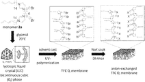
- FIG. 1 comprises a scheme illustrating fabrication of a nanoporous TFC Q I polymer membrane using monomer 2a and post-fabrication anion-exchange with various anions associated at the pore wall.
- FIG. 2 illustrates non-limiting molecular structures of organosulfonate anions exchanged for bromide in the TFC Q I membranes made from monomer 2a.
- FIG. 3A comprises a bar graph illustrating uncharged solute rejections of TFC Q I membranes of 2a anion-exchanged with certain organosulfonate anions.
- the rejection values shown are average values obtained from triplicate experiments.
- the error bars represent the 95% confidence interval.
- FIG. 3B comprises a bar graph illustrating showing organic solute rejection of certain anion-exchanged, cross-linked TFC Q I LLC membranes as a function of anion species associated at the pore wall.
- the control or baseline sample is bromide, highlighted on the left.
- the Stokes diameter for each of the organic solutes is given in the legend.
- FIG. 4 comprises a bar graph illustrating average permeance values of various organosulfonate-exchanged TFC Q I membranes with approximately the same selective layer thickness. The values shown are the averages of triplicate experiments, and the error bars represent the 95% confidence interval.
- FIG. 5 comprises a graph illustrating glycerol rejection vs. (V mol ⁇ log P) of the organosulfonate anion-exchanged into the TFC Q I membranes, showing an empirical relationship of rejection values with the interaction of these two parameters.
- the data points shown represent the average of triplicate experiments, and the error bars represent the 95% confidence interval.
- FIG. 6 comprises EDS spectra of bulk films showing the relative amounts of elemental Br (indicative of the original bromide ion in the pristine Q I polymer film of 2a) and S (indicative of the organosulfonate exchanged in): (a) bromide (control), (b) methanesulfonate, (c) 2-propanesulfonate, (d) benzenesulfonate, and (e) naphthalenesulfonate.
- FIG. 7 comprises a graph illustrating PXRD spectra of bulk films showing the profiles of the initial control Q I film of 2a containing bromide before any anion-exchange, and the organosulfonate-exchanged films.
- FIGS. 9A-9B illustrate ( FIG. 9A ) PXRD and ( FIG. 9B ) SAXS profiles of naphthalenesulfonate-exchanged bulk Q I polymer films of 2a.
- FIG. 10 illustrates PXRD spectra of a polymerized, unsupported bulk Q I film and a polymerized TFC Q I membrane of 2a.
- FIG. 11 illustrates PXRD spectra of TFC Q I membrane samples from the same membrane case, one is the spectra of the original membrane, while the other (treated) is from the sample exchanged to naphthalenesulfonate and used in filtration.
- FIG. 12 comprises a bar graph illustrating uncharged solute rejections of TFC Q I membranes of 2a anion-exchanged with the organosulfonate anions. Also included is the uncharged solute rejection of a commercial RO membrane (SW30HR) and a commercial NF membrane (NF270) (values for commercial membranes collected from Carter, et al., 2012, Chem. Mater. 24:4005-4007, FIG. S16 therein). The rejection values shown are averages values obtained from triplicate experiments. The error bars represent the 95% confidence interval.
- FIG. 13 comprises a bar graph illustrating average permeance values of certain organosulfonate-exchanged TFC Q I membranes with approximately the same selective layer thickness. Water permeance of commercial RO and NF membranes is also included. The values shown are the averages of triplicate experiments, and the error bars represent the 95% confidence interval.
- FIG. 14 comprises a graph illustrating an empirical model relating the rejection of each solute to the interaction of anion and log P is given by the solid line.
- Experimentally observed rejection values shown as an average of triplicate experiments for each organosulfonate-exchanged TFC Q I membrane, are included as the sets of data points.
- the error bars associated with the experimentally observed rejections represent the 95% confidence interval.
- FIG. 15 comprises a graph illustrating empirical plot of the log of the average water flux against the V mol value of the resident anion. Experimentally observed flux, shown as an average of triplicate experiments for each organosulfonate anion, is included as the sets of data points.
- FIG. 16 comprises a bar graph illustrating DI water flux as a function of the anion associated at the pore wall. Control is bromide (left).
- FIG. 17 illustrates non-limiting molecular structures of organosulfonate anions exchanged for bromide in the TFC Q I membranes made from monomer 2a.
- FIG. 18 comprises a graph illustrating PXRD spectra of bulk films showing the profiles of the initial control Q I film of 2a containing bromide before any anion-exchange, and the films exchanged to the organosulfonate anions shown in FIG. 17 .
- FIG. 19 comprises PLM images for a control Q I polymer film of 2a containing bromide, and for bulk films exchanged to the organosulfonate anions presented in FIG. 17 .
- the invention relates to the discovery of methods for reversibly and systematically tuning the effective pore size and/or solute rejection for nanoporous LLC polymer membranes.
- the invention further relates to membranes useful within the methods of the invention.
- the membranes of the invention have high levels of pore size uniformity, based on the good pore size uniformity of the LLC polymer membranes, thereby allowing good separation via size discrimination.
- the porous LLC polymer membrane has a pore structure of interconnected nanopores based on the type I (normal type) bicontinuous cubic (Q I ) LLC phase structure.
- the effective pore size of the modified membrane is equal to or less than about 2.3 nm, about 2.2 nm, about 2.1 nm, about 2.0 nm, about 1.9 nm, about 1.8 nm, about 1.7 nm, about 1.6 nm, about 1.5 nm, about 1.4 nm, about 1.3 nm, about 1.2 nm, about 1.1 nm, about 1 nm, about 0.95 nm, about 0.9 nm, about 0.85 nm, about 0.8 nm, about 0.75 nm, about 0.7 nm, about 0.65 nm, about 0.6 nm, about 0.55 nm, about 0.5 nm, or about 0.45 nm.
- the effective pore size of the structure can be determined by the size of the solute that can be excluded from the membrane.
- the present results demonstrate the ability to manipulate the filtration performance of ionic, Q I -phase LLC polymer NF membranes having ca. 1-2 nm-sized pores. Pore selectivity and water permeance were significantly impacted by anion-exchanging organosulfonate anions at the pore walls without significantly impacting the structural integrity of the material. The impact of the resident anion on membrane performance was described quantitatively by calculation of the effective pore radius via a one-parameter model and demonstrated sub-nm resolution in the variation of effective pore radius. Empirical modeling was used to demonstrate the existence of a correlation between the physicochemical properties of the resident anion and the observed solute rejection.
- the articles “a” and “an” refer to one or to more than one (i.e. to at least one) of the grammatical object of the article.
- an element means one element or more than one element.
- the term “about” will be understood by persons of ordinary skill in the art and will vary to some extent on the context in which it is used. As used herein, “about” when referring to a measurable value such as an amount, a temporal duration, and the like, is meant to encompass variations of ⁇ 20% or ⁇ 10%, more preferably ⁇ 5%, even more preferably ⁇ 1%, and still more preferably ⁇ 0.1% from the specified value, as such variations are appropriate to perform the disclosed methods.
- the term “comprising” includes “including,” “containing,” or “characterized by,” and is inclusive or open-ended and does not exclude additional, unrecited elements or method steps.
- “consisting of” excludes any element, step, or ingredient not specified in the claim element.
- “consisting essentially of” does not exclude materials or steps that do not materially affect the basic and novel characteristics of the claim. Any recitation herein of the term “comprising”, particularly in a description of components of a composition or in a description of elements of a device, is understood to encompass those compositions and methods consisting essentially of and consisting of the recited components or elements.
- electromagnetic radiation includes radiation of one or more frequencies encompassed within the electromagnetic spectrum.
- Non-limiting examples of electromagnetic radiation comprise gamma radiation, X-ray radiation, UV radiation, visible radiation, infrared radiation, microwave radiation, radio waves, and electron beam (e-beam) radiation.
- electromagnetic radiation comprises ultraviolet radiation (wavelength from about 10 nm to about 400 nm), visible radiation (wavelength from about 400 nm to about 750 nm) or infrared radiation (radiation wavelength from about 750 nm to about 300,000 nm).
- UVA light which generally has wavelengths between about 320 and about 400 nm
- UVB light which generally has wavelengths between about 290 nm and about 320 nm
- UVC light which generally has wavelengths between about 200 nm and about 290 nm.
- UV light may include UVA, UVB, or UVC light alone or in combination with other type of UV light.
- the UV light source emits light between about 350 nm and about 400 nm. In some embodiments, the UV light source emits light between about 400 nm and about 500 nm.
- the term “instructional material” includes a publication, a recording, a diagram, or any other medium of expression that may be used to communicate the usefulness of the compositions of the invention.
- the instructional material may be part of a kit useful for generating a system of the invention.
- the instructional material of the kit may, for example, be affixed to a container that contains the compositions of the invention or be shipped together with a container that contains the compositions. Alternatively, the instructional material may be shipped separately from the container with the intention that the recipient uses the instructional material and the compositions cooperatively.
- the instructional material is for use of a kit; instructions for use of the compositions; or instructions for use of a formulation of the compositions.
- LLC monomers are polymerizable amphiphilic molecules that spontaneously self-assemble into fluid, yet highly ordered matrices with regular geometries of nanometer scale dimension when combined with water or another suitable polar organic solvent.
- LLC mesogens are amphiphilic molecules comprising one or more hydrophobic organic tails and a hydrophilic headgroup. In certain embodiments, the headgroup is ionic.
- an “LLC polymer” or “LLC polymer composition” comprises polymerized LLC monomers in an ordered assembly.
- the LLC polymer composition may also comprise an initiator and/or a cross-linking agent.
- a porous LLC polymer is formed when the ordered assembly comprises pores or channels of solvent surrounded by the LLC monomers, and the resulting assembly is covalently linked together with preservation of the LLC phase structure.
- the LLC polymer does not comprise functional groups such as halogen (unless as a counterion for maintaining overall charge neutrality with a cationic LLC polymer), hydroxyl, carbonyl, carboxylic acid, primary amine, or secondary amine.
- a “membrane” is a barrier separating two fluids that allows transport between the fluids.
- Porous LLC polymer membranes useful for the invention comprise a porous LLC polymer.
- the membrane to be modified is a “composite” membrane comprising a porous LLC polymer composition combined with a porous support.
- the porous LLC polymer membrane is a nanoporous membrane.
- a “monodisperse” pore size has a variation in pore size from one pore to another of less than ca. 15% (specifically, an ideally narrow Poisson distribution).
- the pore size of a given pore varies along the pore channel.
- the pore size is monodisperse when measured in this way.
- the pore size may be measured by its minimum dimension.
- the effective pore size of the structure may be determined by the size of the solute that can be excluded from the pore manifold.
- the term “nanoporous” refers to a pore size between about 0.5 and about 6 nm in diameter, and a “nanofiltration membrane” has an effective pore size between about 0.5 and about 6 nm.
- the LLC polymer portion of the composite may be nanoporous while the porous support has a larger average pore size.
- the unmodified LLC polymer composition has an effective pore size between about 0.5 and 5.0 nm. In other embodiments the effective pore size greater than or equal to 0.5 to less than 2 nm, from 0.5 to 1 nm, or less than 2 nm.
- polymer refers to a molecule composed of repeating structural units typically connected by covalent chemical bonds.
- polymer is also meant to include the terms copolymer and oligomers.
- a “polymerizable LLC monomer” comprises a polymerizable group which allows covalent bonding of the monomer to another molecule such as another monomer, polymer or cross-linking agent.
- the organic tails may be linked together during polymerization.
- Suitable polymerizable groups include acrylate, methacrylate, diene, vinyl, (halovinyl), styrenes, vinylether, hydroxy groups, epoxy or other oxiranes (halooxirane), dienoyls, diacetylenes, styrenes, terminal olefins, isocyanides, acrylamides, and cinamoyl groups.
- the polymerizable group is an acrylate, methacrylate, or diene group.
- polymerization refers to at least one reaction that consumes at least one functional group in a monomeric molecule (or monomer), oligomeric molecule (or oligomer) or polymeric molecule (or polymer), to create at least one chemical linkage between at least two distinct molecules (e.g., intermolecular bond), at least one chemical linkage within the same molecule (e.g., intramolecular bond), or any combination thereof.
- a polymerization reaction may consume between about 0% and about 100% of the at least one functional group available in the system. In certain embodiments, polymerization of at least one functional group results in about 100% consumption of the at least one functional group. In other embodiments, polymerization of at least one functional group results in less than about 100% consumption of the at least one functional group.
- Type (I) photo-initiator refers to a compound that undergoes a unimolecular bond cleavage upon irradiation to yield free radicals.
- Type (I) photo-initiators are benzoin ethers, benzyl ketals, ⁇ -dialkoxy-acetophenones, ⁇ -hydroxy-alkylphenones, ⁇ -amino-alkylphenones and acyl-phosphine oxides.
- Type (II) photo-initiator refers to a combination of compounds that undergo a bimolecular reaction where the excited state of the photoinitiator interacts with a second molecule (often known as “co-initiator”) to generate free radicals.
- ALD atomic layer deposition
- DI deionized
- EDS energy-dispersive X-ray spectroscopy
- LLC lyotropic liquid crystal
- MWCO molecular weight cut-off
- NF nanofiltration
- PLM polarized light microscopy
- PXRD particle X-ray diffraction
- RO reverse osmosis
- SAXS small-angle X-ray scattering
- TFC thin-film composite
- TOC total organic carbon
- range format is merely for convenience and brevity and should not be construed as an inflexible limitation on the scope of the invention. Accordingly, the description of a range should be considered to have specifically disclosed all the possible sub-ranges as well as individual numerical values within that range and, when appropriate, partial integers of the numerical values within ranges. For example, description of a range such as from 1 to 6 should be considered to have specifically disclosed sub-ranges such as from 1 to 3, from 1 to 4, from 1 to 5, from 2 to 4, from 2 to 6, from 3 to 6 etc., as well as individual numbers within that range, for example, 1, 2, 2.7, 3, 4, 5, 5.3, and 6. This applies regardless of the breadth of the range.
- lyotropic liquid crystals (LLCs) to membrane filtration offers a solution to limitations of pore size manipulation and uniformity in NF membranes.
- the TFC Q I membrane based on monomer 2a (shown in FIG. 1 ) offers unique avenues to directly manipulate the nanopore characteristics.
- the connected network of hydrophilic regions in a TFC Q I membrane is discrete, being defined by the cationic head groups of the LLC monomers that form the pore walls.
- An anion associated at the cationic pore wall is held by electrostatic interactions rather than covalent bonds, allowing for this anion to be mobile and completely exchange with other anions in solution.
- the anion associated at the pore wall can be referred to as the resident anion.
- the resident anion impacts transport of water and solutes through the pore. Soaking of a TFC Q I membrane based on 2a in a salt solution does afford complete anion-exchange, meaning the anion from the solution completely replaces the original anion associated at the pore wall, so long as the new anion is small enough to enter the pores.
- ion-exchange in LLC-based NF membranes for the control of uncharged solute rejection has not been previously demonstrated.
- the present work investigates the impact of anion-exchange on the uncharged solute rejection and water permeance of the TFC Q I membrane based on 2a using certain anions of varying size.
- the impact of anion-exchange was qualitatively evaluated by observing changes in uncharged solute rejection.
- solute rejection is a result of pore selectivity.
- the impact of anion-exchange on pore selectivity was quantified via the calculation of the effective pore radius using a one-parameter model.
- An empirical model was used to investigate the relationship between the various physicochemical properties of the resident anion (i.e., molecular volume and hydrophobicity) and the uncharged solute rejection of the resulting membrane.
- control factor i.e., resident anion property
- response i.e., solute rejection
- different porous architectures can be achieved via the use of LLC monomers that form different mesophases in a solvent. Depending on where they appear on the phase diagram relative to the central lamellar (L ⁇ ) phase, these phases can be classified as Type I (oil-in-water or normal) or Type II (water-in-oil or inverted).
- the pores of the mesophase are filled with the solvent, the solvent being a polar liquid such as water or an aqueous solution.
- the hydrophilic headgroups of the LLC mesogens are oriented towards the pores of the mesophase, “lining” the pores.
- the LLC phase structure may be a polydomain structure, and thus may display short-range rather than long-range order.
- non-aqueous solvent-based LLC systems are known in the literature. These water-free LLC phases are formed around organic solvents such as ethylene glycol, glycerol, formamide, N-methylformamide, dimethylformamide, N-methylsydnone, (Auvray, et al., 1992, Langmuir 8:2671), and some imidazolium-based room-temperature ionic liquids (RTILs) (Greaves & Drummond, 2008, J. Chem. Soc. Rev. 37:1709), instead of water.
- organic solvents such as ethylene glycol, glycerol, formamide, N-methylformamide, dimethylformamide, N-methylsydnone, (Auvray, et al., 1992, Langmuir 8:2671), and some imidazolium-based room-temperature ionic liquids (RTILs) (Greaves & Drummond, 2008, J. Chem. Soc. Rev. 37:1709
- LLC monomers useful for the present invention may be polymerized into a crosslinked network with substantial retention of the original LLC phase microstructure.
- contraction of the structure is observed on heavy crosslinking of the polymer into a network.
- Expansion of Q I unit cells has been observed for some LLC monomers (Pindzola, et al., 2003, J. Am. Chem. Soc. 125(10): 2940-2949).
- Some disordering of the phases may also be observed upon cross-linking, as evidenced by a loss in X-ray diffraction (XRD) peak intensity.
- XRD X-ray diffraction
- the pore structure after polymerization is substantially determined or controlled by the Q phase that is formed by the monomers.
- the pore structure can be based on the Q LLC structure.
- the pore structure after polymerization need not be identical to that of the Q LLC phase.
- the pore structure of the polymerized network retains at least part of the Q phase structure and comprises interconnected, ordered 3-D nanopores. Retention of the Q phase structure can be confirmed through observation of PXRD peaks characteristic of the structure.
- the LLC polymer has a pore structure of interconnected nanopores.
- polymerizable LLC phases with Q LLC architectures have interconnected 3-D nanochannels. These phases are termed bicontinuous because they have two or more unconnected but interpenetrating hydrophobic and/or solvent networks with overall cubic symmetry.
- the polymerized network has a pore structure of interconnected, ordered 3-D nanopores.
- the pore structure is substantially determined or controlled by the Q phase formed by the monomers.
- the LLC polymer composition has a pore structure of interconnected nanopores based on the type I (normal type) bicontinuous cubic (Q I ) LLC phase structure. For Q, phases, the size of the gap between the organic portions of the structure determines the effective pore size of the structure.
- Several polymerizable LLCs are known to spontaneously form Q I LC phases. These mesogens include gemini surfactant monomers. Monomer 1 forms a Q I phase (Pindzola, Ph.D. Thesis (2001), University of California, Berkeley).
- the spacer and tail length of the gemini surfactant are “matched”, with larger spacer lengths corresponding to longer tail lengths.
- RTILs room temperature ionic liquids
- the polymerizable gemini imidazolium surfactant composition is monomer 2: [(P—Y)—H-L-H—(Y—P)] 2+ .(2/ n )[X n ] Monomer 2, wherein: H is a hydrophilic head group comprising a five membered cationic aromatic ring containing two nitrogens (e.g., an imidazolium ring);
- X is an anion of negative charge n
- L is a spacer or linking group which connects the two headgroup rings
- Y is a hydrophobic tail group attached to each ring and having at least 10 carbon atoms and comprising a polymerizable group P.
- Each spacer L is attached to a first nitrogen atom in each of the two linked rings.
- the attachment can be through a covalent or a noncovalent bond, such as an ionic linkage.
- Each hydrophobic tail group Y is attached to the second (other, non-bridged) nitrogen atom in each ring.
- the combination of the hydrophilic head group H, the linker L, and the hydrophobic tail Y form an imidazolium cation.
- Monomer 2 is an imidazolium-based polymerizable gemini surfactant that forms Q LLC phases with RTILs and water as the polar solvent.
- m is 0 to 6 or 3-7.
- the anion present in the surfactant or monomer, X is a standard anion used in preparing RTILs.
- These anions include, but are not limited to BR ⁇ , BF 4 ⁇ , Cl ⁇ , I ⁇ , CF 3 SO 3 ⁇ , Tf 2 N ⁇ (and other large fluorinated anions), PF 6 ⁇ , DCA ⁇ , MeSO 3 ⁇ , and TsO ⁇ .
- the anion X ⁇ is selected from the group consisting of Br ⁇ and BF 4 ⁇ .
- Suitable polymerizable groups include acrylate, methacrylate, diene, vinyl, (halovinyl), styrenes, vinylether, hydroxy groups, epoxy or other oxiranes (halooxirane), dienoyls, diacetylenes, styrenes, terminal olefins, isocyanides, acrylamides, and cinnamoyl groups.
- the polymerizable group is an acrylate, methacrylate or diene group.
- the polymerizable group is an acrylate group.
- the tail group may have some portions that are more hydrophobic than others (e.g., if the tail contains a polymerizable group attached to an alkyl chain), but the tail group is overall hydrophobic with respect to the headgroup portion of the molecule.
- Certain polymerizable LLCs i.e., cross-linkable surfactants
- H II inverted hexagonal
- Polymerizable LLCs can also spontaneously form the inverted hexagonal (H II ) LLC phase in the presence of a small amount of water.
- robust polymer networks containing hexagonally packed, extended water channels with monodisperse diameters of nanometer-scale dimensions are produced.
- the network has a pore structure of hexagonally ordered, cylindrical nanopores.
- the pore structure is substantially determined or controlled by the inverted hexagonal phase formed by the monomers.
- the LLC polymer composition has a pore structure of nanopores based on the type II (inverted) hexagonal (H II ) structure.
- Polymerizable LLCs may also form lamellar phases.
- H II -phase forming monomers are typically taper-shaped molecules, and some examples (monomers 3-6) are shown below.
- the pores of the as-synthesized LLC polymer composition may be filled with water, an aqueous solution, or some other polar liquid.
- the pores of the LLC polymer composition may be filled with the polar liquid by using this liquid as the solvent in the LLC mixture.
- the porous LLC polymer composition is embedded within a porous support membrane, thereby forming a composite membrane.
- the LLC polymer composition fills enough of the support pore space, so that separation process is controlled by the pores of the LLC polymer composition.
- the LLC polymer composition is present throughout the thickness of the support, so that the thickness of the composite membrane may be taken as the thickness of the support.
- the LLC mixture may be applied to only a portion of the surface of the support.
- the LLC polymer composition may be retained within the support by mechanical interlocking of the LLC polymer composition with the support.
- the membrane to be modified comprises a porous support, and a porous LLC polymer composition attached to the support.
- the LLC polymer composition has a pore structure of interconnected nanopores based on the type I (normal type) Q I LLC phase structure.
- the LLC polymer composition comprises a polymer network formed from polymerizable LLC monomers and optional cross-linking agents.
- the LLC polymer composition is formed by polymerization of an LLC mixture which forms the type I (normal type) Q I LLC phase, the LLC mixture comprising polymerizable LLC monomers and a solvent and not including a hydrophobic polymer, the LLC polymer composition comprising a pore structure of interconnected nanopores based on the type I bicontinuous cubic LLC structure. The polymerizable LLC monomers are assembled in the type I (normal type) Q I prior to polymerization.
- the LLC polymer composition forms a layer on the surface of the support; this layer acts as a membrane.
- the thickness of this layer is less than 10 microns, less than 5 microns, less than 2 microns, less than 1 micron, or less than 0.5 microns.
- the porous support is hydrophilic.
- a hydrophilic support is wettable by water and capable of spontaneously absorbing water.
- the hydrophilic nature of the support may be measured by various methods known to those skilled in the art, including measurement of the contact angle of a drop of water placed on the membrane surface, the water absorbency (weight of water absorbed relative to the total weight, U.S. Pat. No. 4,720,343) and the wicking speed (U.S. Pat. No. 7,125,493).
- the observed macroscopic contact angle of a drop of water placed on the membrane surface may change with time.
- the contact angle of a 2 ⁇ L drop of water placed on the support surface is less than about 90 degrees, from about 5 degrees to about 85 degrees, about zero degrees to about 30 degrees or is about 70 degrees.
- the membrane is fully wetted by water and soaks all the way through the membrane after about one minute.
- Hydrophilic polymeric supports include supports formed of hydrophilic polymers and supports which have been modified to make them hydrophilic. In other embodiments, the support is hydrophobic.
- the porous support membrane has a smaller flow resistance than the LLC membrane.
- the porous support in this system is selected so that the diameter of the pores is less than about 10 microns and greater than the effective pore size of the LLC polymer composition.
- the support is microporous or ultraporous.
- the support has a pore size less than about 0.1 micron or from 0.1 micron to 10 microns.
- the preferred pore size of the support may depend on the composition of the LLC mixture.
- the characteristic pore size of the membrane may depend on the method used to measure the pore size.
- Methods used in the art to determine the pore size of membranes include Scanning Electron Microscopy analysis, capillary flow porometry analysis (which gives a mean flow pore size), measurement of the bubble pressure (which gives the largest flow pore size), and porosimetry.
- the porous support membrane can give physical strength to the composite structure.
- the support membrane can also add flexibility to the composite membrane.
- the support should also be thermally stable over approximately the same temperature range as the LLC membranes to be used.
- the support is selected to be compatible with the solution used for LLC membrane formation, as well as to be compatible with the liquid or gas to be filtered.
- the support is resistant to swelling and degradation by the solution used to cast the LLC polymer porous membrane.
- the organic solvent used in the solution and the support are selected to be compatible so that the support is substantially resistant to swelling and degradation by the organic solvent. Swelling and/or degradation of the support by the solvent may lead to changes in the pore structure of the support.
- the porous support is sufficiently hydrophilic for water permeation.
- the porous support may be made of any suitable material known to those skilled in the art including polymers, metals, and ceramics.
- the porous polymer support comprises polyethylene (including high molecular weight and ultra high molecular weight polyethylene), polyacrylonitrile (PAN), polyacrylonitrile-co-polyacrylate, polyacrylonitrile-co-methylacrylate, polysulfone (PSf), Nylon 6,6, poly(vinylidene difluoride), or polycarbonate.
- the support is a polyethylene support or a support of another polymer mentioned elsewhere herein (including surface treatments to affect the wettability of the support).
- the support may also be an inorganic support such as a nanoporous alumina disc (Anopore, J. Whatman, Ann Arbor, Mich.).
- the porous support can also be a composite membrane.
- the solution used for applying the LLC monomer also known as the “LLC mixture”
- the solution used for applying the LLC monomer comprises a plurality of polymerizable LLC monomers, an aqueous or polar organic solvent, and a polymerization initiator.
- a single species of polymerizable LLC monomer may be used, but a plurality of monomers is required for phase formation.
- the aqueous or polar solvent is selected so that the LLC monomer forms the desired Q I phase. Because of the LLC phase formation, the solution formed may not be uniform.
- suitable polar liquid solvents include, but are not limited to water, dimethylformamide, and THF or room temperature ionic liquids.
- suitable polar organic solvents suitable as water substitutes for LLC assembly include ethylene glycol, glycerol, formamide, N-methylformamide, dimethylformamide, or N-methylsydnone, most of which are fairly water-miscible, protic organic solvents, with the exception of N-methylsydnone.
- RTILs are polar, molten organic salts under ambient conditions that are typically based on substituted imidazolium, phosphonium, ammonium, and related organic cations complemented by a relatively non-basic and non-nucleophilic large anion.
- the solvent is aqueous.
- the polymerization initiator can be photolytically or thermally activated. The mixture is thoroughly combined. In certain embodiments, mixing may be performed through a combination of hand mixing and centrifuging.
- the LLC mixture does not further comprise a hydrophobic polymer as described by Lu et al., 2006, Adv. Mater. 18(24): 3294-3298 and U.S. Pat. No. 7,090,788.
- the LLC mixture may further comprise an optional cross-linking agent molecule to help promote intermolecular bonding between polymer chains.
- the crosslinking agent is not required if the monomer can cross-link without a cross-linking agent. In certain embodiments, the cross-linking agent is not a polymer. In certain embodiments, the cross-linking agent has less than 10 monomeric repeat units and/or has a weight less than 500 daltons.
- the cross-linking agent or curing agent is a small molecule or monomeric cross linker such as divinylbenzene (DVB), and are known to those skilled in the art.
- the amount of cross-linking agent is small enough to allow formation of the desired LLC phase.
- the cross-linker is typically hydrophobic, in order to dissolve in and help to cross-link the hydrophobic tail regions of the LLC phase.
- the incorporation of additional hydrophobic components into the LLC mixture may be limited to prevent the overall polymeric composition from being too hydrophobic for good water filtration.
- the maximum amount of cross-linking agent is 10 wt % to 15 wt %.
- when the cross-linking agent is hydrophobic its size is kept small enough so that reduction of the overall density or surface coverage of the polar solvent (e.g., water) nanopores is limited.
- the photo-initiator contemplated within the invention is a molecule that, upon irradiation with a given wavelength at a given intensity for a given period of time, generates at least one species capable of catalyzing, triggering or inducing a polymerization or crosslinking.
- a photo-initiator known in the art may be employed, such as a benzoin ether and a phenone derivative such as benzophenone or diethoxyacetophenone.
- the irradiation comprises ultraviolet electromagnetic radiation (wavelength about 10-400 nm), visible electromagnetic radiation (wavelength about 400-750 nm) or infrared electromagnetic radiation (radiation wavelength about 750-300,000 nm).
- the electromagnetic radiation comprises ultraviolet or visible electromagnetic radiation.
- UVA light which generally has wavelengths between about 320 and about 400 nm
- UVB light which generally has wavelengths between about 290 nm and about 320 nm
- UVC light which generally has wavelengths between about 200 nm and about 290 nm.
- UV light may include UVA, UVB, or UVC light alone or in combination with other type of UV light.
- the UV light source emits light between about 350 nm and about 400 nm. In some embodiments, the UV light source emits light between about 400 nm and about 500 nm.
- Non-limiting examples of the photoinitiator contemplated within the invention are: 1-hydroxy-cyclohexyl-phenyl-ketone (IRGACURE® 184; Ciba, Hawthorne, N.J.); a 1:1 mixture of 1-hydroxy-cyclohexyl-phenyl-ketone and benzophenone (IRGACURE® 500; Ciba, Hawthorne, N.J.); 2-hydroxy-2-methyl-1-phenyl-1-propanone (DAROCUR® 1173; Ciba, Hawthorne, N.J.); 2-hydroxy-1-[4-(2-hydroxyethoxy)phenyl]-2-methyl-1-propanone (IRGACURE® 2959; Ciba, Hawthorne, N.J.); methyl benzoylformate (DAROCUR® MBF; Ciba, Hawthorne, N.J.); oxy-phenyl-acetic acid 2-[2-oxo-2-phenyl-acetoxy-e
- the photo-initator can be used in amounts ranging from about 0.01 to about 25 weight percent (wt %) of the composition, more preferably from about 0.1 to about 20 weight percent (wt %) of the composition, more preferably from about 1 to about 15 weight percent (wt %) of the composition, more preferably from about 2 to about 10 weight percent (wt %) of the composition.
- the mixture may further comprise an organic solvent for formulation or delivery of the LLC monomer (e.g., for solvent casting).
- the solvent may be any low boiling point organic solvent that dissolves the monomer.
- a mixture of one or more solvents may also be used.
- Useful solvents include, but are not limited to, methanol and diethyl ether.
- the monomer is dissolved in the organic solvent, and then the water and the optional cross-linking agent are added.
- the organic solvent used in the solution and the support are selected to be compatible so that the support is substantially resistant to swelling and degradation by the organic solvent. Swelling and/or degradation of the support by the solvent can lead to changes in the pore structure of the support.
- the composition of the LLC mixture may be selected to obtain the desired Q based on the phase diagram for the LLC monomer. For example, at atmospheric pressure the LLC phases present in the system may be determined as a function of temperature and percentage of amphiphile (LLC monomer) in the system. The percentage of LLC monomer in the mixture and the temperature may then be selected together to obtain the desired Q phase. When the phase of LLC mixture is sensitive to the water or other solvent content, steps may be taken to minimize evaporative water or solvent loss during the membrane fabrication process.
- the weight percent of water in the LLC mixture is from 5% to 15 wt %. Temperature control may be needed to maintain the phase during the photo-cross-linking after infiltration into the support membrane (i.e., ca. 70° C.). In other embodiments, the concentration of the imidazolium-based LLC surfactant or monomer is between 10% and 100%.
- the LLC mixture is assembled into the LLC phase before the mixture is contacted with the porous support.
- the mixture may be allowed to rest at room temperature or at any suitable temperature dictated by the phase diagram.
- Analysis of the LLC phases can be performed by several methods known to those skilled in the art including polarized light microscopy (PLM) and powder X-ray diffraction (PXRD).
- Q phases are optically isotropic (have a black optical texture) when viewed with the PLM.
- PXRD of Q phases exhibit symmetry-allowed d spacings that ideally proceed in the ratio 1:1/sqrt(2): 1/sqrt(3): 1/sqrt(4): 1/sqrt(5): 1/sqrt(6): 1/sqrt(8): 1/sqrt(9): 1/sqrt(10): and so forth, corresponding to the d 100 , d 110 , d 111 , d 200 , d 210 , d 211 , d 220 , d 221 (or d 300 ), d 310 , and so forth diffraction planes.
- the presence of Q phases with P or I symmetry in polydomain small molecule amphiphile and phase separated block copolymer systems has generally been identified on the basis of a black optical texture and a PXRD profile in which the 1/sqrt(6): and 1/sqrt(8): d spacings (i.e., the d 211 and d 220 reflections) are at least present.
- the higher order PXRD reflections may be used to distinguish between the different 3-D cubic phase architectures, since systematic absences in the PXRD peaks result as the cubic cells becomes more complex. However, the higher order reflections may not be observed when the phases do not possess a great deal of long range order.
- the LLC mixture has a fluid gel-like consistency before cross-linking or polymerization.
- a quantity of the LLC mixture is placed on a surface of the porous support membrane and then infused into the porous support.
- the support is impregnated with the LLC mixture using a combination of heat and pressure to drive the LLC mixture into the pores of the support. The temperature and pressure are selected so that LLC phase is still retained.
- the LLC mixture and support can be heated to decrease the viscosity of the LLC mixture before pressure is applied.
- a heated press may be used to impregnate the support with the LLC mixture. When a press is used, the LLC mixture and support membrane may be sandwiched between a pair of load transfer plates.
- a pair of polymeric sheets may be used to facilitate release of the support mixture and membrane from the load transfer plates and limit evaporation of water from the mixture.
- Suitable dense polymeric sheets that are transparent to UV or visible light include, but are not limited to, MYLAR® (a biaxially-oriented polyester film made from ethylene glycol and dimethyl teraphthalate).
- the LLC mixture need not completely fill the pore space of the support, but fills enough of the pore space of the support so that separation process is controlled by the pores of the LLC polymer composition. In certain embodiments, the gel is pushed uniformly through the entire support membrane thickness.
- the LLC monomers are then cross-linked to form the LLC polymer composition.
- the LLC monomers are polymerized by cross-linking the hydrophobic tails.
- the LLC phase can be photo-cross-linked by putting it under UV light in air or nitrogen at ambient temperature (or at the required temperature to maintain the desired LLC phase). Other temperatures as known by those skilled in the art may be used during the cross-linking process. Other methods of crosslinking as known to those skilled in the art may also be used. For example, thermal cross-linking can be performed using a cationic initiator as a cross-linking agent. The degree of cross-linking can be assessed with infrared (IR) spectroscopy.
- IR infrared
- the degree of polymerization is greater than 90% or greater than 95%.
- the LLC polymer composition is formed as a thin, supported top-film on top of the support.
- the coating of the LLC monomer mixture is formed by solution-casting the LLC monomer mixture to make thin films on membrane supports after evaporation of the delivery solvent; doctor-blade draw-casting of the initial viscous LLC monomer gel; or roll-casting of the LLC mixture at elevated temperature. Coating can be free of surface defects such as pinholes and scratches.
- a commercial foam painting sponge or other such applicator may be used to apply the solution to the support.
- the solution may be applied by roller casting. The amount of material on the support may be controlled by the number of applications and the concentration of the casting solution. If desired, more than one layer of solution may be applied to the support to form multiple layers of porous LLC polymer and thereby control the film thickness.
- the solvent content e.g., water content
- the solvent content is controlled by limiting evaporation of solvent from the film. Evaporation of the solvent can be controlled by sandwiching the LLC film and support between polymer sheets, processing the LLC film and support in an enclosure in which the atmosphere is controlled (e.g., the humidity level is controlled), and by other methods known to those skilled in the art. Enclosing the LLC film may also prevent other components from entering into LLC monomer film.
- the invention provides a nanoporous lyotropic liquid crystal (LLC) polymer membrane.
- the membrane comprises a cationic LLC polymer and at least one anionic counterion.
- the polymer comprises at least one pore, in which at least one anionic counterion is located.
- the at least one anionic counterion modulates (e.g., decreases or increases) an uncharged solute selectivity of the LLC polymer membrane as compared to the LLC polymer membrane wherein a control inactive counterion is located in the at least one pore.
- the control inactive counterion is a halide, such as but not limited to fluoride, chloride, bromide, and/or iodide.
- the at least one anionic counterion is selected from the group consisting of optionally substituted linear, cyclic, or branched C 1 -C 6 alkanesulfonate, optionally substituted benzenesulfonate, optionally substituted naphthalenesulfonate, optionally substituted trifluoromethanesulfonate, and optionally substituted camphorsulfonate.
- the at least one anionic counterion is selected from the group consisting of optionally substituted alkyl- or aromatic-based carboxylates, including but not limited to propionate and benzoate, as well as optionally substituted alkyl- or aromatic-based phosphonates, including but not limited to methylphosphonate and phenylphosphonate.
- an anionic counterion is optionally substituted with at least one substituent selected from the group consisting of ether, ester, alcohol, ketone, amine, amide, thiol, sulfide, aldehyde, and halide.
- the anionic counterion is optionally substituted with at least one selected from the group consisting of C 1 -C 6 alkyl, C 1 -C 6 haloalkyl, C 1 -C 6 haloalkoxy, fluoro, chloro, bromo, iodo, cyano, nitro, —SR′, —C( ⁇ O)R′, —N(R′)(R′), —OR′, —C( ⁇ O)OR′, and —C( ⁇ O)NR′R′, wherein each occurrence of R′ is independently H or C 1 -C 6 alkyl.
- the counterion is monovalent or multivalent. In other embodiments, the counterion is a poly(anionic) molecule that contains multiple, covalently bonded anionic functional groups such as sulfonate or carboxylate groups.
- Non-limiting examples of such molecular poly(anions) are aryl- or alkyldisulfonates (e.g., benzene 1,3-disulfonate and 1,3-propanedisulfonate) and aryl- and alkyldicarboxylates (e.g., benzene 1,3-dicarboxylate and 1,3-propanedicarboxylate).
- aryl- or alkyldisulfonates e.g., benzene 1,3-disulfonate and 1,3-propanedisulfonate
- aryl- and alkyldicarboxylates e.g., benzene 1,3-dicarboxylate and 1,3-propanedicarboxylate
- the effective size of the at least one pore is equal to or less than about 2 nm, or about 1.5 nm, or about 1.0 nm.
- the at least one pore has a structure selected from the group consisting of type I bicontinuous cubic (Q I ) LLC phase structure, and inverted hexagonal (H II ) LLC phase structure.
- the LLC polymer is formed by polymerization of at least one polymerizable LLC monomer selected from the group consisting of monomers 1-6, and any combinations thereof.
- the LLC polymer is formed by polymerization of at least one polymerizable LLC monomer 2a.
- the at least one anionic counterion is selected from the group consisting of methanesulfonate, ethanesulfonate, 1-propanesulfonate, 2-propanesulfonate, benzenesulfonate, p-toluenesulfonate, m-toluenesulfonate, o-toluenesulfonate, ⁇ -naphthalenesulfonate, ⁇ -naphthalenesulfonate and camphorsulfonate.
- the polymer is embedded within a porous support membrane or deposited as a layer on the surface of a porous support membrane.
- the invention provides a method of preparing a nanoporous LLC polymer membrane, wherein the membrane comprises a cationic LLC polymer and at least one anionic counterion, wherein the LLC polymer membrane further comprises at least one pore, in which the at least one anionic counterion is located, and wherein the effective size of the at least one pore is equal to or less than about 2 nm, or about 1.5 nm, or about 1.0 nm.
- the invention further provides a method of modifying the effective pore size and/or solute rejection of a nanoporous LLC polymer membrane, wherein the membrane comprises a cationic LLC polymer and at least one first anionic counterion, wherein the LLC polymer membrane further comprises at least one pore, in which the at least one first anionic counterion is located, and wherein the effective size of the at least one pore is equal to or less than about 2 nm, or about 1.5 nm, or about 1.0 nm.
- the method further provides a method of increasing the concentration of an uncharged solute in a first solution, using a nanoporous LLC polymer membrane comprising a cationic LLC polymer and at least one anionic counterion, wherein the polymer comprises in the at least one pore that connects in a fluidic manner a first surface of the membrane and a second surface of the membrane, wherein the effective radius of the at least one pore is equal to or less than about 2 nm, or about 1.5 nm, or about 1.0 nm, wherein the at least one anionic counterion is located in the at least one pore, and wherein the Stokes diameter of the uncharged solute is approximately equal to the effective radius for the at least one pore of the membrane,
- the method comprises contacting the membrane with a solution comprising the at least one given counterion that modulates the uncharged solute selectivity of the LLC polymer membrane as compared to the LLC polymer membrane wherein a control inactive counterion is located in the at least one pore.
- the at least one counterion is selected from the group consisting of optionally substituted liner, branched, or cyclic C 1 -C 6 alkanesulfonate, optionally substituted benzenesulfonate, optionally substituted naphthalenesulfonate, optionally substituted trifluoromethanesulfonate, and optionally substituted camphorsulfonate.
- the at least one given counterion is selected from the group consisting of optionally substituted alkyl- or aromatic-based carboxylates, including but not limited to propionate and benzoate, as well as optionally substituted alkyl- or aromatic-based phosphonates, including but not limited to methylphosphonate and phenylphosphonate.
- the counterion is a poly(anionic) molecule that contains multiple, covalently bonded anionic functional groups such as sulfonates, carboxylate, and/or phosphonate groups.
- anionic functional groups such as sulfonates, carboxylate, and/or phosphonate groups.
- molecular poly(anions) are aryl- or alkyldisulfonates (e.g., benzene 1,3-disulfonate and 1,3-propanedisulfonate), aryl- and alkyldicarboxylates (e.g., benzene 1,3-dicarboxylate and 1,3-propanedicarboxylate), and/or aryl- or alkyldiphosphonates (e.g., benzene 1,3-diphosphonate and 1,3-propanediphosphonate).
- the at least one pore has a structure selected from the group consisting of type I bicontinuous cubic (Q I ) LLC phase structure, and inverted hexagonal (H II ) LLC phase structure.
- the method comprises replacing the at least one first anionic counterion with at least one second anionic counterion, wherein the effective pore size and/or solute rejection of the membrane comprising the at least one first anionic counterion is distinct from that comprising the at least one second anionic counterion.
- the method comprises contacting the first solution with the first surface of the membrane, whereby a second solution with a lower concentration of the uncharged solute than the first solution is formed on the second surface of the membrane.
- the polymer is formed by polymerization of at least one polymerizable LLC monomer selected from the group consisting of monomers 1-6, and any combinations thereof. In certain embodiments, the polymer is formed by polymerization of at least one polymerizable LLC monomer 2a.
- the at least one anionic counterion is selected from the group consisting of methanesulfonate, ethanesulfonate, 1-propanesulfonate, 2-propanesulfonate, benzenesulfonate, p-toluenesulfonate, m-toluenesulfonate, o-toluenesulfonate, ⁇ -naphthalenesulfonate, ⁇ -naphthalenesulfonate and camphorsulfonate.
- the at least one counterion is selected from the group consisting of optionally substituted liner, branched, or cyclic C 1 -C 6 alkanesulfonate, optionally substituted benzenesulfonate, optionally substituted naphthalenesulfonate, optionally substituted trifluoromethanesulfonate, and optionally substituted camphorsulfonate.
- the at least one given counterion is selected from the group consisting of optionally substituted alkyl- or aromatic-based carboxylates, including but not limited to propionate and benzoate, as well as optionally substituted alkyl- or aromatic-based phosphonates, including but not limited to methylphosphonate and phenylphosphonate.
- the counterion is a poly(anionic) molecule that contains multiple, covalently bonded anionic functional groups such as sulfonates or carboxylate groups.
- anionic functional groups such as sulfonates or carboxylate groups.
- molecular poly(anions) are aryl- or alkyldisulfonates (e.g., benzene 1,3-disulfonate and 1,3-propanedisulfonate) and aryl- and alkyldicarboxylates (e.g., benzene 1,3-dicarboxylate and 1,3-propanedicarboxylate).
- the LLC polymer is embedded within a porous support membrane or deposited as a layer on the surface of a porous support membrane.
- the replacing step comprises contacting the nanoporous LLC polymer membrane with a solution comprising the at least one second anionic counterion.
- the at least one first anionic counterion has a distinct molecular volume (V mol ) from the at least one second anionic counterion.
- the membrane comprising the at least one second anionic counterion has distinct % rejection for an uncharged solute than the membrane comprising the at least one first anionic counterion.
- the Stokes diameter of the uncharged solute is approximately equal to the effective pore radius for the membrane comprising the at least one second anionic counterion.
- the effective radius for the at least one pore of the membrane is about equal to or lower than the Stokes diameter of the uncharged solute.
- the LLC polymer is embedded within a porous support membrane or deposited as a layer on the surface of a porous support membrane.
- NMR spectroscopy was performed using a Bruker Avance-III 300 NMR spectrometer (300 MHz for 1 H). Films were cast using an MTI Corporation automatic film coater (MSK-AFA-III-110) equipped with a 0.95 cm diameter #3 wire-wound rod from the Paul N. Gardner Company. Films were annealed with a temperature programmed XTREME® hot/cold plate from LR Technologies and radically photopolymerized in a Coy Labs polymer glove box purged with dry N 2 gas (O 2 content ⁇ 3%, as measured by an Alpha Omega OXY-SEN sensor).
- Samples requiring more peak resolution than could be provided by the PXRD were characterized by small-angle X-ray scattering (SAXS) using a Rigaku SAXS system with a Cu rotating anode equipped with a 2D multi-wire detector.
- SAXS small-angle X-ray scattering
- the optical character of bulk films was evaluated via polarized light microscopy (PLM) using a Leica DMRXP polarized light microscope with a Q-imaging MicroPublisher 3.3 RTV digital camera.
- Bulk films and TFC membranes were imaged via scanning electron microscopy (SEM) using a JEOL JSM-6480LV scanning electron microscope; the qualitative presence of various elements was evaluated via energy-dispersive X-ray spectroscopy (EDS) using INCA software.
- SEM scanning electron microscopy
- EDS energy-dispersive X-ray spectroscopy
- Monomer 2a was synthesized according to Carter, et al., 2012, Chem. Mater. 24:4005-4007.
- Monomer 2a can form the Q I LLC phase in an unsupported bulk film (ca. 200 ⁇ m thick) or in a thin film (ca. 5 ⁇ m thick) as the skin layer of a TFC membrane; the formulation and fabrication procedures for both these forms of Q I -phase films are provided for example in Carter, et al., 2012, Chem. Mater. 24:4005-4007; Carter, et al., 2014, J. Membr. Sci. 455:143-151). The only deviations from the procedures reported in prior work are the use of an automatic roll-casting machine and a different commercial support for the fabrication of the TFC membranes.
- the LLC order in the polymerized bulk films was evaluated with both PXRD and PLM, while the order in the polymerized LLC phase of the skin layer isolated from a TFC membrane was evaluated by PXRD.
- Circular TFC Q I membrane discs (4.9 cm 2 ) were cut from a TFC Q I membrane sheet and soaked under the conditions necessary to induce complete anion-exchange for the given anion. Upon completion of the anion-exchange, the discs were loaded into the dead-end filtration units resulting in an exposed membrane area of 2.8 cm 2 . The feed side of the filtration cell was then filled with DI water and brought to a pressure of 27.6 bar over a period of 12 min using nitrogen gas. DI water was then run through the system until at least 5 mL of permeate was collected; initial flux readings were taken.
- the feed was changed to a 2000 mg/L aqueous solution of one of the uncharged solutes (sucrose, glucose, glycerol, or ethylene glycol), and the system was allowed to come to steady state by passing 5 mL of permeate. Then, three sequential permeate samples of 1-5 mL each were collected, and samples were stored in the fridge for TOC analysis. Permeate and feed samples were diluted with DI water into the range of 2-15 mg/L carbon for TOC analysis. Anion-exchanged membranes were tested in triplicate and with a control membrane having the original bromide anion still present.
- one of the uncharged solutes sucrose, glucose, glycerol, or ethylene glycol
- V perm V perm ⁇ d AtP ( Equation ⁇ ⁇ 1 )
- V perm the volume of permeate collected
- d active layer thickness (about 5 ⁇ m for the TFC Q I membrane)
- A is the exposed area of the membrane (2.8 cm 2 )
- t is the time it took to collect that volume of permeate
- P is the applied pressure (27.6 bar).
- This research uses two models as a way of analyzing the rejection results in order to explore the system as a whole. These models provide insight about what is occurring and help predict the response that would be induced by anions not included in the scope of this work.
- the one-parameter model a Nernst-Planck-based model that includes hindered transport in the pores, can determine the effective pore radius of a given membrane through fitting this model to experimentally observed rejection values of uncharged solutes with established molecular dimensions (Bowen & Welfoot, 2002, Chem. Eng. Sci. 57:1121-1137).
- This model takes into account transport by both convection and diffusion but only includes steric interactions.
- This model is effective at modeling the performance of NF membranes in general, and has been used to calculate the effective pore radius in Q I LLC polymer membranes. In prior pore radius modeling work, the annular nanopores of the Q I phase were treated as a laterally packed collection of cylinders of the same diameter throughout the material.
- EDS was used to analyze the elements present.
- Bulk films were freeze-fractured under liquid N 2 so that the center of the cross-section could be analyzed with EDS ( FIG. 6 ).
- the control was coated with gold to increase imaging capacity; the gold peak is in the same region as the sulfur peak.
- the elemental bromine peak was diminished and the elemental sulfur peak was dominant.
- EDS was not used to quantify the amount of exchange; if the concentration of Br was below 1 wt % (the detection limit of the method), it was assumed to be completely exchanged out. All the organosulfonate-exchanged films met this requirement, demonstrating that complete anion-exchange was achieved.
- the LLC phase of the bulk films was evaluated via PXRD ( FIG. 7 ).
- the peak below 1.5 degrees in 2theta is an artifact of the machine.
- Each film demonstrated one LLC peak around 2.3 degrees in 2theta, suggesting similar structure to the original bromide control.
- This peak corresponds to the 1/ ⁇ 6 d-spacing, while the peak around 5 degrees in 2theta corresponds to the 1/ ⁇ 22 d-spacing peak, both characteristic of a Q phase.
- Intensity of the signal is a function of amount of material in the beam path and duration of spectra collection, therefore it is not quantified here.
- the PXRD spectrum for the naphthalenesulfonate-exchanged bulk films of cross-linked 2a only shows an intense main 1/ ⁇ 6 d-spacing peak, plus an additional weaker 1/ ⁇ 22 d-spacing peak that can also be indexed a Q LLC phase ( FIG. 9A ).
- the SAXS spectrum of the same material offers further resolution of the region near the intense main 1/ ⁇ 6 peak.
- the dominant and shoulder peaks shown in the higher-resolution SAXS spectrum correspond to the 1/ ⁇ 6:1/ ⁇ 8 d-spacings characteristic of a Q LLC phase ( FIG. 9B ).
- the PXRD spectra in combination with PLM images confirm that the pore structure, namely the Q phase, was maintained for all organosulfonate anions exchanged-in.
- SAXS confirmed the presence of the Q phase. All of these analyses were done with unsupported bulk film samples. Due to the small amount of LLC material present in the TFC Q I membrane relative to the commercial support material, the LLC phase is difficult to characterize in the TFC membrane. However, a comparison of the PXRD spectrum of the TFC membrane to the PXRD spectrum of an unsupported bulk film polymerized under the same conditions ( FIG. 10 ) suggests that the nanostructure of the TFC membrane is very similar to that of the polymerized bulk film.
- the materials were assumed to be anion-exchanged to the same degree with retention of the LLC phase structure.
- Conditions and characterization that afforded complete anion-exchange in the bulk films were applied the TFC membranes.
- FIG. 12 illustrates the observed solute rejection results of organosulfonate-exchanged TFC Q I membranes from FIG. 3A alongside the solute rejection of commercial NF (NF270 by Dow Filmtec) and RO (SW30HR by Dow Filmtec) membranes.
- FIG. 13 compares the water permeance of organosulfonate-exchanged membranes to commercial RO and NF membranes.
- the rejection performance of the TFC Q I membrane is higher or lower than the commercial NF membrane depending on the resident anion and the uncharged solute.
- the permeance of the exchanged TFC Q I membranes is higher or lower than that of the commercial RO membrane, depending on the resident anion. Both of these graphs demonstrate a significant range of performance achievable by the TFC Q I membrane by a simple switching of the resident anion.
- the one-parameter model used to calculate the effective pore radius from the observed uncharged solute rejection is fully developed in Bowen & Welfoot, 2002, Chem. Eng. Sci. 57:1121-1137; a summary of the applicable equations is given in Table 2.
- the equation numbers provided refer to the numbering in Bowen and Welfoot's publication.
- the osmotic pressure difference, ⁇ was calculated following the ASTM Standard D4516, where m i is molality of the solution.
- the effective pore radius for each organosulfonate-exchanged membrane was determined by minimizing the sum squared error between the experimental and theoretical (modeled) rejection for each solute simultaneously, using Excel's Solver. The constants used are provided in Table 3.
- the effective pore radius induced by a given anion was reported as the average value calculated from the triplicate membrane tests.
- the error provided with the average effective pore radius is the 90% confidence interval based on the variation between the triplicate runs.
- the ability of this model to describe the observed performance was evaluated using the calculation of the standard error between rejection predicted by the model (Rej calc ) and experimentally observed rejection (Rej exp ), as given by Equation 3:
- Linear regression was evaluated for the rejection of each solute as a function of the various anion properties based on the adjusted coefficient of determination, adjusted R 2 .
- FIG. 14 shows the fitted empirical relationship of rejection vs. (V mol ⁇ log P) compared to the experimentally observed rejection for all uncharged solutes.
- Table 4 provides the adjusted R 2 values for the fit of each solute rejection and each anion property function investigated.
- FIG. 15 presents the experimentally observed water flux as well as the empirical model.
- Equation 3 was used to calculate the standard error between this model and the experimentally observed rejection results.
- this model groups the data by solute (i.e., the rejection of glycerol as a function of the anion) as opposed to by anion (i.e., the rejection of an anion-exchanged membrane as a function of the uncharged solute being rejected)
- the “j ⁇ p” term is replaced by “i ⁇ p” in the denominator.
- the empirical model used two parameters: the slope and the intercept of the fitted line.
- organosulfonate anions were chosen.
- sulfonate is the monovalent anion with the highest affinity for the quaternary ammonium cation, which is very similar to the cationic imidazolium head group that forms the pore walls in the Q I system presented here. This means that organosulfonate anions are not easily displaced by other anions once it is associated at the pore wall.
- organosulfonates are commercially available, allowing for different subsets to be chosen to explore different types of properties for the resident anion.
- the chemical structures of the organosulfonate anions used are shown in FIG. 2 , and their molecular weights, V mol , and log P values are listed in Table 5.
- LC and LLC phases can be quantitatively identified by PXRD if at least two peaks are present.
- the two most common PXRD peaks used to identify the Q phase are the 1/ ⁇ 6 and 1/ ⁇ 8 d-spacings.
- the typically lower-intensity 1/ ⁇ 8 peak may or may not be distinguishable. In such cases, the presence of a single PXRD peak can be coupled with the PLM image to identify the specific LLC phase.
- the Q I phase has overall cubic symmetry and therefore produces a dark image, representative of a pseudo-isotropic material, in the presence of polarized light.
- Anisotropic LLC phases generate a birefringent, or brightly textured, image in the presence of polarized light. Therefore, a material demonstrating a single LLC PXRD peak and a dark image on the PLM can be inferred to have cubic symmetry with a high level of confidence.
- Most of the organosulfonate-exchanged bulk films exhibited both a single LLC PXRD peak and a dark image on the PLM, demonstrating that the nanopore network formed by the Q I phase order was not lost during anion-exchange.
- the bulk naphthalenesulfonate-exchanged film had a LLC peak in its PXRD spectrum but showed a bright, silver-textured image under PLM, which is inconsistent with a Q phase.
- SAXS analysis affording better signal-to-noise and resolution, showed that the naphthalenesulfonate-exchanged film had the dominant 1/ ⁇ 6 d-spacing peak and lower-intensity 1/ ⁇ 8 shoulder peak indicative of a Q phase.
- the Q phase was maintained after anion-exchange to each organosulfonate anion studied.
- the organosulfonate-exchanged TFC Q I membranes were then tested for filtration performance under pressurized dead-end filtration conditions. Single-solute aqueous solutions were fed to the membranes, and uncharged solute rejection was calculated from the feed and permeate concentrations, as measured by TOC analysis.
- the pore size of the TFC Q I membranes made from 2a are on the order of 1 nm (Carter, et al., 2012, Chem. Mater. 24:4005-4007).
- FIG. 3A presents the rejection of these uncharged solutes in the TFC Q I membranes exchanged with each organosulfonate anion tested.
- the uncharged solute rejection of the TFC Q I membranes depends significantly on the resident organosulfonate anion. While membranes containing methanesulfonate and 2-propanesulfonate rejected the solutes to the same extent, their rejection was significantly lower than those containing benzenesulfonate, which were significantly lower than those containing naphthalenesulfonate.
- the water permeance of the anion-exchanged membranes was also evaluated as a function of resident anion. Water permeance is typically inversely proportional to membrane selectivity. A more selective membrane with smaller pores should have a lower water permeance, all else being equal. This expected trend can be seen in the water permeance results in FIG. 4 for some of the organosulfonate-containing TFC Q I membranes of approximately the same thickness. TFC Q I polymer membranes that have higher rejections have correspondingly lower water permeance. This trend is not present, however, in the comparison of methanesulfonate and 2-propanesulfonate. Membranes exchanged with these two anions have the same uncharged solute selectivity ( FIG. 3 ), but they differ greatly in their water permeance.
- the one-parameter model was used to characterize the nanopore environment in a quantitative way. Since the one-parameter model describes solute rejection well in these types of Q I membranes, it was used here to elucidate the impact of the resident organosulfonate anion on the nanopore through the calculation of the effective pore radius. By taking the rejection results presented in FIG. 3A and fitting them to the one-parameter model via the effective pore radius (r pore ), one can calculate the effective pore radius (Table 6) of a membrane with a given resident anion. The standard error between the model and the experimentally observed rejection data was 0.09, indicating that the one-parameter model described the results well.
- Table 6 shows that the effective pore radius of the TFC Q I membrane varied significantly with the resident organosulfonate anion.
- the one-parameter model is one method of quantifying the selectivity of the pore. Based on the results presented in Table 6, this method can induce sub-nm variations in pore selectivity.
- the single terms investigated were the individual factors themselves (V mol or log P) and the interaction term (V mol ⁇ log P).
- the interaction term was important to include in this analysis because it includes both factors while maintaining the single-term form of the model. The simultaneous inclusion of both factors was necessary to consider given the strong collinearity between the factors.
- the quality of fit as represented by the adjusted R 2 value, varies with solute. The best correlation was found with glycerol, which falls in the middle of the rejection range at about 50%. Experimentally observed solute rejection and the empirical model are presented in FIG. 5 to visually represent the quality of fit. The adjusted R 2 values for all single-term models describing the rejection of all solutes is provided elsewhere herein. The variation in quality of fit with solute agrees with the importance of solute-membrane interaction on rejection. Solutes vary in their physicochemical properties just as the resident anions do, causing the interaction between solute and membrane to look slightly different for each solute. Similarly, the physicochemical properties of solutes and water differ.
- a library-based approach requires an extensive library of all possible anions in order to find the right resident anion to induce a desired membrane performance.
- a property-based approach uses information from previous experiments in order to predict which anion will induce the desired membrane performance based on the anion's properties.
- Such an approach coupled with a set of organosulfonate anions not characterized by the collinearity present here could also contribute significantly to the understanding of solute and solvent transport within the nanopore environment.
- the correlation presented here is specific to the family of organosulfonate anions and might vary for other families of anions. However, as long as a correlation can be found within an anion family, this approach can offer insight about that anion family.
- a property-based approach contributes to the development of designable materials for NF applications.
Landscapes
- Chemical & Material Sciences (AREA)
- Chemical Kinetics & Catalysis (AREA)
- Engineering & Computer Science (AREA)
- Organic Chemistry (AREA)
- Manufacturing & Machinery (AREA)
- Materials Engineering (AREA)
- Health & Medical Sciences (AREA)
- Medicinal Chemistry (AREA)
- Polymers & Plastics (AREA)
- Inorganic Chemistry (AREA)
- Crystallography & Structural Chemistry (AREA)
- Physics & Mathematics (AREA)
- Plasma & Fusion (AREA)
- Separation Using Semi-Permeable Membranes (AREA)
Abstract
Description

[(P—Y)—H-L-H—(Y—P)]2+.(2/n)[Xn]
H is a hydrophilic head group comprising a five membered cationic aromatic ring containing two nitrogens (e.g., an imidazolium ring);


where Vperm is the volume of permeate collected, d is active layer thickness (about 5 μm for the TFC QI membrane), A is the exposed area of the membrane (2.8 cm2), and t is the time it took to collect that volume of permeate, and P is the applied pressure (27.6 bar).
where Cperm and Cfeed are the solute concentrations in the permeate and feed, respectively.
Analysis
| TABLE 1 |
| Conditions (concentration and salt soak duration) used |
| to induce complete anion-exchange of the bulk QI |
| films for each organosulfonate anion used. |
| Aq. Soak | ||||
| Solution | ||||
| Concentration | Soak Duration | |||
| Anion | (M) | (days) | ||
| bromide (control) | 0 | 2 | ||
| methanesulfonate | 1 | 2 | ||
| 2-propanesulfonate | 0.2 | 1 | ||
| benzenesulfonate | 0.5 | 2 | ||
| naphthalenesulfonate | saturated | 4 | ||
| TABLE 2 |
| Equations used to fit the one-parameter model to experimentally observed results. |
| Rejection |
|
(12) |
| Ratio of permeate concentration to feed concentration |
|
(10) |
| Modified Peclet number |
|
(16) |
| Dimensionless variable |
|
(9) |
| Solute pore diffusion coefficient | Dp = KdD∞ | |
| Hindrance factor for convection | Kc = (2 − ϕ)(1.0 + 0.054λ − 0.988λ2 + 0.441λ3) | |
| Hindrance factor for diffusion | Kd = (1.0 + 2.30λ − 1.154λ2 + 0.224λ3) | |
| Steric partition coefficient | ϕ = (1 − λ)2 | |
| Ratio of solute radius to pore radius |
|
|
| Solvent viscosity within the pore |
|
(14) |
| Effective transmembrane pressure drop | ΔPe = ΔP − Δπ | (1) |
| Osmotic pressure | π = 8.308 * 0.9(T + 273.15)mi | (A1.1) |
| TABLE 3 |
| Constant values used in the one-parameter model, with |
| their units and sources. |
| Property | Symbol | Value | Units | Source |
| radius of sucrose | rs | 4.7E−10 | m | [b] |
| radius of glucose | rg | 3.65E−10 | m | [b] |
| radius of glycerol | rgly | 2.6E−10 | m | [b] |
| radius of ethylene glycol | reg | 2.14E−10 | m | [c] |
| bulk diffusion of sucrose | D∞s | 5.2E−10 | m2/s | [b] |
| bulk diffusion of glucose | D∞g | 6.9E−10 | m2/s | [b] |
| bulk diffusion of glycerol | D∞gly | 9.5E−10 | m2/s | [b] |
| bulk diffusion of ethylene glycol | D∞eg | 1.135E−09 | m2/s | [d] |
| partial molar volume of sucrose | Vs | 0.000212 | m3/mol | [e] |
| partial molar volume of glucose | Vg | 0.000112 | m3/mol | [e] |
| partial molar volume of glycerol | Vgly | 0.00007084 | m3/mol | [f] |
| partial molar volume of ethylene | Veg | 0.00005442 | m3/mol | [f] |
| glycol | ||||
| bulk solvent viscosity | η0 | 0.0009 | N s/m2 | Engineering |
| Toolbox | ||||
| ideal gas constant | R | 8.314 | J/mol K | |
| diameter of a water molecule | do2 | 2.8E−10 | m | [a] |
| temperature | T | 298 | K | |
| feed concentration | Cf | 2000 | ppm | |
| applied transmembrane pressure | ΔP | 26.6 | bar | |
| drop | ||||
| [a] Bowen & Welfoot, 2002, Chem. Eng. Sci. 57: 1121-1137. | ||||
| [b] Bowen, et al., 1997, J. Membr. Sci. 126: 91-105. | ||||
| [c] Hatakeyama, et al., 2011, J. Membr. Sci. 366: 62-72. | ||||
| [d] Fernandez-Sempere, et al., 1996, J. Chem. Eng. Data 41: 47-48. | ||||
| [e] Sato & Miyawaki, 2016, Food Chem. 190: 594-598. | ||||
| [f] Kiyosawa, 1991, Biochim. Biophys. Acta 1064: 251-255. | ||||
where j represents the anion, i represents the solute, n represents the number of replicates, and p represents the number of parameters used to fit the model. The parameter used to fit the one-parameter model to experimental data was the pore radius (rpore).
where the solute is the salt. The molecular volume (Vmol) provided by Chemicalize dot org was calculated from the van der Waals radii of the individual atoms and the presence of chemical bonds. This information source was chosen above others because it provided values for all the anions of interest, removing the concern of incomparable values due to differences in the calculation method. In the series of organosulfonate anions chosen here, log P increases with Vmol. This is because overall anion size was increased through the addition of carbon and hydrogen atoms to the hydrocarbon unit of the organosulfonate anion, so as to avoid the inclusion of other functional groups that might introduce confounding effects other than size and hydrophobicity. While other factors including surface morphology and hydrogen bonding impact uncharged solute rejection, these membrane characteristics are not changed during anion-exchange to the various organosulfonates of interest here. For this reason, only Vmol and log P were of interest.
y=mx+b (Equation 5)
where x is the single-term factor, y is the observed rejection, m is the fitted slope of the correlation, and b is the fitted intercept. Linear regression was evaluated for the rejection of each solute as a function of the various anion properties based on the adjusted coefficient of determination, adjusted R2.
| TABLE 4 |
| Adjusted R2 values for the fit of the linear regression model |
| based on different anion properties. For each solute, the |
| independent variable that produced the highest R2 value |
| is highlighted in yellow. |
| Single-factor terms (X) |
| Solute | Vmol | logP | (Vmol · logP) | ||
| sucrose | 0.344 | 0.405 | 0.400 | ||
| glucose | 0.708 | 0.771 | 0.784 | ||
| glycerol | 0.827 | 0.779 | 0.890 | ||
| ethylene glycol | 0.770 | 0.713 | 0.844 | ||
| water | 0.990 | 0.935 | 0.980 | ||
| TABLE 5 |
| Molecular weights, Vmol, and logP values for the resident |
| organosulfonate anions. (Chemicalize dot org, April 2016) |
| Mol. Wt. | Vmol | ||||
| Organosulfonate Anion | (g/mol) | (Å3) | logP | ||
| methanesulfonate | 95.1 | 70.3 | −0.96 | ||
| 2-propanesulfonate | 123.1 | 104.4 | 0.12 | ||
| benzenesulfonate | 157.2 | 124.0 | 1.15 | ||
| naphthalenesulfonate | 207.2 | 167.2 | 2.14 | ||
Anion-Exchange of Bulk and TFC QI Polymer Membranes: Conditions and Characterization
| TABLE 6 |
| The effective pore radius as calculated by fitting the |
| one-parameter model to rejection results of a TFC QI |
| membrane anion-exchanged with the specified organosulfonate |
| anion. The values shown are the averages of triplicate |
| experiment, and the error bars represent the 90% confidence |
| interval. |
| Effective | |||
| Exchanged-in | pore radius, | ||
| organosulfonate anion | rpore (nm) | ||
| Methanesulfonate | 0.9 ± 0.2 | ||
| 2-propanesulfonate | 0.9 ± 0.2 | ||
| Benzenesulfonate | 0.67 ± 0.04 | ||
| naphthalenesulfonate | 0.55 ± 0.08 | ||
| TABLE 7 |
| Conditions (concentration and salt soak duration) used |
| to induce complete anion-exchange of the bulk QI |
| films for each organosulfonate anion used. |
| Aq. Soak Solution | Soak Duration | |||
| Anion | Concentration (M) | (days) | ||
| bromide (control) | 0 | 2 | ||
| trifluoromethanesulfonate | 0.2 | 3 | ||
| ethanesulfonate | 0.2 | 3 | ||
| pentanesulfonate | 0.2 | 3 | ||
| 1,3-propanedisulfonate | 0.2 | 3 | ||
| benzene 1,3-disulfonate | 0.5 | 3 | ||
Claims (6)
Priority Applications (1)
| Application Number | Priority Date | Filing Date | Title |
|---|---|---|---|
| US15/879,902 US11046826B2 (en) | 2017-01-26 | 2018-01-25 | Nanoporous lyotropic liquid crystal polymer membranes with reversibly tuned pore size and selectivity, and methods using same |
Applications Claiming Priority (2)
| Application Number | Priority Date | Filing Date | Title |
|---|---|---|---|
| US201762450776P | 2017-01-26 | 2017-01-26 | |
| US15/879,902 US11046826B2 (en) | 2017-01-26 | 2018-01-25 | Nanoporous lyotropic liquid crystal polymer membranes with reversibly tuned pore size and selectivity, and methods using same |
Publications (2)
| Publication Number | Publication Date |
|---|---|
| US20180208728A1 US20180208728A1 (en) | 2018-07-26 |
| US11046826B2 true US11046826B2 (en) | 2021-06-29 |
Family
ID=62906041
Family Applications (1)
| Application Number | Title | Priority Date | Filing Date |
|---|---|---|---|
| US15/879,902 Active 2038-09-07 US11046826B2 (en) | 2017-01-26 | 2018-01-25 | Nanoporous lyotropic liquid crystal polymer membranes with reversibly tuned pore size and selectivity, and methods using same |
Country Status (1)
| Country | Link |
|---|---|
| US (1) | US11046826B2 (en) |
Families Citing this family (3)
| Publication number | Priority date | Publication date | Assignee | Title |
|---|---|---|---|---|
| US11433359B1 (en) * | 2018-01-29 | 2022-09-06 | Arrowhead Center, Inc. | Antimicrobial filtration membranes |
| IT201800003374A1 (en) * | 2018-03-08 | 2019-09-08 | Consiglio Naz Delle Richerche | Membranes containing polymerized ionic liquids for use in gas separation. |
| US12398324B1 (en) * | 2024-05-30 | 2025-08-26 | Tokyo Electron Limited | Methods for controlling the pitch of self-assembled ionic liquid crystal (ILC) structures |
Citations (10)
| Publication number | Priority date | Publication date | Assignee | Title |
|---|---|---|---|---|
| US7090788B2 (en) * | 2003-04-24 | 2006-08-15 | Tda Research, Inc. | Nanoporous composites of polymerized lyotropic liquid-crystalline monomers, and hydrophobic polymers |
| US20080029735A1 (en) * | 2006-07-03 | 2008-02-07 | Gin Douglas L | Surfactants and polymerizable surfactants based on room-temperature ionic liquids that form lyotropic liquid crystal phases with water and room-temperature ionic liquids |
| US20080179188A1 (en) * | 2007-01-30 | 2008-07-31 | Eksigent Technologies, Inc. | Methods, compositions and devices, including electroosmotic pumps, comprising coated porous surfaces |
| US7521003B2 (en) * | 2003-02-14 | 2009-04-21 | The Regents Of The University Of Colorado | Functionalized nanostructured lyotropic liquid crystal polymers |
| US20090173693A1 (en) * | 2007-05-15 | 2009-07-09 | Gin Douglas L | Lyotropic liquid crystal membranes based on cross-linked type i bicontinuous cubic phases |
| US7604129B2 (en) * | 2002-10-03 | 2009-10-20 | The Regents of the Univeristy of Colorado, a body corporate | Lyotropic liquid crystal nanofiltration membranes |
| US20120160095A1 (en) * | 2010-11-29 | 2012-06-28 | The Regents Of The University Of Colorado, A Body Corporate | Novel Nanoporous Supported Lyotropic Liquid Crystal Polymer Membranes and Methods of Preparing and Using Same |
| US20130190417A1 (en) * | 2012-01-23 | 2013-07-25 | Wisconsin Alumni Research Foundation | Polymerizable gemini dicarboxlate surfactants and lyotropic liquid crystals and membranes made therefrom |
| US20130306907A1 (en) * | 2012-05-16 | 2013-11-21 | Wisconsin Alumni Research Foundation (Warf) | Dicarboxylate gemini surfactant that forms a lyotropic liquid crystal |
| US20140154499A1 (en) * | 2011-07-22 | 2014-06-05 | The Regents Of The University Of Colorado, A Body Corporate | Method and Membrane for Nanoporous, Bicontinuous Cubic Lyotropic Liquid Crystal Polymer Membranes that Enable Facile Film Processing and Pore Size Control |
-
2018
- 2018-01-25 US US15/879,902 patent/US11046826B2/en active Active
Patent Citations (11)
| Publication number | Priority date | Publication date | Assignee | Title |
|---|---|---|---|---|
| US7604129B2 (en) * | 2002-10-03 | 2009-10-20 | The Regents of the Univeristy of Colorado, a body corporate | Lyotropic liquid crystal nanofiltration membranes |
| US7521003B2 (en) * | 2003-02-14 | 2009-04-21 | The Regents Of The University Of Colorado | Functionalized nanostructured lyotropic liquid crystal polymers |
| US7090788B2 (en) * | 2003-04-24 | 2006-08-15 | Tda Research, Inc. | Nanoporous composites of polymerized lyotropic liquid-crystalline monomers, and hydrophobic polymers |
| US20080029735A1 (en) * | 2006-07-03 | 2008-02-07 | Gin Douglas L | Surfactants and polymerizable surfactants based on room-temperature ionic liquids that form lyotropic liquid crystal phases with water and room-temperature ionic liquids |
| US7931824B2 (en) * | 2006-07-03 | 2011-04-26 | The Regents Of The University Of Colorado | Surfactants and polymerizable surfactants based on room-temperature ionic liquids that form lyotropic liquid crystal phases with water and room-temperature ionic liquids |
| US20080179188A1 (en) * | 2007-01-30 | 2008-07-31 | Eksigent Technologies, Inc. | Methods, compositions and devices, including electroosmotic pumps, comprising coated porous surfaces |
| US20090173693A1 (en) * | 2007-05-15 | 2009-07-09 | Gin Douglas L | Lyotropic liquid crystal membranes based on cross-linked type i bicontinuous cubic phases |
| US20120160095A1 (en) * | 2010-11-29 | 2012-06-28 | The Regents Of The University Of Colorado, A Body Corporate | Novel Nanoporous Supported Lyotropic Liquid Crystal Polymer Membranes and Methods of Preparing and Using Same |
| US20140154499A1 (en) * | 2011-07-22 | 2014-06-05 | The Regents Of The University Of Colorado, A Body Corporate | Method and Membrane for Nanoporous, Bicontinuous Cubic Lyotropic Liquid Crystal Polymer Membranes that Enable Facile Film Processing and Pore Size Control |
| US20130190417A1 (en) * | 2012-01-23 | 2013-07-25 | Wisconsin Alumni Research Foundation | Polymerizable gemini dicarboxlate surfactants and lyotropic liquid crystals and membranes made therefrom |
| US20130306907A1 (en) * | 2012-05-16 | 2013-11-21 | Wisconsin Alumni Research Foundation (Warf) | Dicarboxylate gemini surfactant that forms a lyotropic liquid crystal |
Non-Patent Citations (2)
| Title |
|---|
| Carter, et al., Thin-film Composite Bicontinuous Cubic Lyotropic Liquid Crystal Polymer Membranes: Effects of Anion-exchange on Water Filtration Performance, J. Membrane Science, 455, 2014 , pp. 143. |
| Gin, D.L. et al., "Abstracts of Papers, 252nd ACS National Meeting & Exposition," Philadelphia, PA, United States, Aug. 21-25, 2016, PMSE-508. |
Also Published As
| Publication number | Publication date |
|---|---|
| US20180208728A1 (en) | 2018-07-26 |
Similar Documents
| Publication | Publication Date | Title |
|---|---|---|
| US20090173693A1 (en) | Lyotropic liquid crystal membranes based on cross-linked type i bicontinuous cubic phases | |
| Jadav et al. | Synthesis of novel silica-polyamide nanocomposite membrane with enhanced properties | |
| Huang et al. | Molecularly-porous ultrathin membranes for highly selective organic solvent nanofiltration | |
| Dai et al. | Incorporation of an ionic liquid into a midblock-sulfonated multiblock polymer for CO2 capture | |
| Liu et al. | Ion–ion selectivity of synthetic membranes with confined nanostructures | |
| Valentino et al. | Development and performance characterization of a polyimine covalent organic framework thin-film composite nanofiltration membrane | |
| Ma et al. | Effect of type of poly (ethylene glycol)(PEG) based amphiphilic copolymer on antifouling properties of copolymer/poly (vinylidene fluoride)(PVDF) blend membranes | |
| US20240058767A1 (en) | Polymeric composite membranes having oriented nanochannels and methods of making the same | |
| Bargeman et al. | Nanofiltration of multi-component feeds. Interactions between neutral and charged components and their effect on retention | |
| JP7678623B2 (en) | Preparation of filtration membrane | |
| Peng et al. | Transport, structural, and interfacial properties of poly (vinyl alcohol)–polysulfone composite nanofiltration membranes | |
| White | Transport properties of a polyimide solvent resistant nanofiltration membrane | |
| Kong et al. | Co-solvent-mediated synthesis of thin polyamide membranes | |
| Wang et al. | High-surface-area functionalized nanolaminated membranes for energy-efficient nanofiltration and desalination in forward osmosis | |
| Foglia et al. | Neutron reflectivity and performance of polyamide nanofilms for water desalination | |
| US11046826B2 (en) | Nanoporous lyotropic liquid crystal polymer membranes with reversibly tuned pore size and selectivity, and methods using same | |
| Dischinger et al. | Effect of post-polymerization anion-exchange on the rejection of uncharged aqueous solutes in nanoporous, ionic, lyotropic liquid crystal polymer membranes | |
| McCormick et al. | Water, salt, and ethanol diffusion through membranes for water recovery by forward (direct) osmosis processes | |
| US20120160095A1 (en) | Novel Nanoporous Supported Lyotropic Liquid Crystal Polymer Membranes and Methods of Preparing and Using Same | |
| Ebrahim et al. | On the influence of salt concentration on the transport properties of reverse osmosis membranes in high pressure and high recovery desalination | |
| Liu et al. | Interfacial self-organization of large-area mixed-dimensional polyamide membranes for rapid aqueous nanofiltration | |
| Horne et al. | Effect of branched and cycloalkyl functionalities on CO2 separation performance of poly (IL) membranes | |
| Berradi et al. | Optimization of the synthesis of ultrafiltration asymmetric membranes based on organic polymers | |
| Benito et al. | The fabrication of ultrathin films and their gas separation performance from polymers of intrinsic microporosity with two-dimensional (2D) and three-dimensional (3D) chain conformations | |
| Darvishmanesh et al. | Coupled series–parallel resistance model for transport of solvent through inorganic nanofiltration membranes |
Legal Events
| Date | Code | Title | Description |
|---|---|---|---|
| FEPP | Fee payment procedure |
Free format text: ENTITY STATUS SET TO UNDISCOUNTED (ORIGINAL EVENT CODE: BIG.); ENTITY STATUS OF PATENT OWNER: SMALL ENTITY |
|
| FEPP | Fee payment procedure |
Free format text: ENTITY STATUS SET TO SMALL (ORIGINAL EVENT CODE: SMAL); ENTITY STATUS OF PATENT OWNER: SMALL ENTITY |
|
| AS | Assignment |
Owner name: THE REGENTS OF THE UNIVERSITY OF COLORADO, A BODY CORPORATE, COLORADO Free format text: ASSIGNMENT OF ASSIGNORS INTEREST;ASSIGNORS:GIN, DOUGLAS L.;NOBLE, RICHARD D.;DISCHINGER, SARAH MARIE;AND OTHERS;SIGNING DATES FROM 20180209 TO 20180222;REEL/FRAME:045141/0746 Owner name: THE REGENTS OF THE UNIVERSITY OF COLORADO, A BODY Free format text: ASSIGNMENT OF ASSIGNORS INTEREST;ASSIGNORS:GIN, DOUGLAS L.;NOBLE, RICHARD D.;DISCHINGER, SARAH MARIE;AND OTHERS;SIGNING DATES FROM 20180209 TO 20180222;REEL/FRAME:045141/0746 |
|
| STPP | Information on status: patent application and granting procedure in general |
Free format text: DOCKETED NEW CASE - READY FOR EXAMINATION |
|
| AS | Assignment |
Owner name: NATIONAL SCIENCE FOUNDATION, VIRGINIA Free format text: CONFIRMATORY LICENSE;ASSIGNOR:UNIVERSITY OF COLORADO;REEL/FRAME:045634/0738 Effective date: 20180419 |
|
| STPP | Information on status: patent application and granting procedure in general |
Free format text: NON FINAL ACTION MAILED |
|
| STPP | Information on status: patent application and granting procedure in general |
Free format text: RESPONSE TO NON-FINAL OFFICE ACTION ENTERED AND FORWARDED TO EXAMINER |
|
| STPP | Information on status: patent application and granting procedure in general |
Free format text: ADVISORY ACTION MAILED |
|
| STPP | Information on status: patent application and granting procedure in general |
Free format text: DOCKETED NEW CASE - READY FOR EXAMINATION |
|
| STPP | Information on status: patent application and granting procedure in general |
Free format text: NOTICE OF ALLOWANCE MAILED -- APPLICATION RECEIVED IN OFFICE OF PUBLICATIONS |
|
| STPP | Information on status: patent application and granting procedure in general |
Free format text: PUBLICATIONS -- ISSUE FEE PAYMENT VERIFIED |
|
| STCF | Information on status: patent grant |
Free format text: PATENTED CASE |
|
| FEPP | Fee payment procedure |
Free format text: SURCHARGE FOR LATE PAYMENT, SMALL ENTITY (ORIGINAL EVENT CODE: M2554); ENTITY STATUS OF PATENT OWNER: SMALL ENTITY |
|
| MAFP | Maintenance fee payment |
Free format text: PAYMENT OF MAINTENANCE FEE, 4TH YR, SMALL ENTITY (ORIGINAL EVENT CODE: M2551); ENTITY STATUS OF PATENT OWNER: SMALL ENTITY Year of fee payment: 4 |