US11045263B1 - System and method for generating a virtual jig for surgical procedures - Google Patents
System and method for generating a virtual jig for surgical procedures Download PDFInfo
- Publication number
- US11045263B1 US11045263B1 US16/788,198 US202016788198A US11045263B1 US 11045263 B1 US11045263 B1 US 11045263B1 US 202016788198 A US202016788198 A US 202016788198A US 11045263 B1 US11045263 B1 US 11045263B1
- Authority
- US
- United States
- Prior art keywords
- virtual
- instrument
- grid
- jig
- bone
- Prior art date
- Legal status (The legal status is an assumption and is not a legal conclusion. Google has not performed a legal analysis and makes no representation as to the accuracy of the status listed.)
- Active
Links
Images


Classifications
-
- A—HUMAN NECESSITIES
- A61—MEDICAL OR VETERINARY SCIENCE; HYGIENE
- A61B—DIAGNOSIS; SURGERY; IDENTIFICATION
- A61B34/00—Computer-aided surgery; Manipulators or robots specially adapted for use in surgery
- A61B34/10—Computer-aided planning, simulation or modelling of surgical operations
-
- A—HUMAN NECESSITIES
- A61—MEDICAL OR VETERINARY SCIENCE; HYGIENE
- A61B—DIAGNOSIS; SURGERY; IDENTIFICATION
- A61B34/00—Computer-aided surgery; Manipulators or robots specially adapted for use in surgery
- A61B34/20—Surgical navigation systems; Devices for tracking or guiding surgical instruments, e.g. for frameless stereotaxis
-
- G—PHYSICS
- G02—OPTICS
- G02B—OPTICAL ELEMENTS, SYSTEMS OR APPARATUS
- G02B27/00—Optical systems or apparatus not provided for by any of the groups G02B1/00 - G02B26/00, G02B30/00
- G02B27/01—Head-up displays
- G02B27/017—Head mounted
-
- G—PHYSICS
- G06—COMPUTING OR CALCULATING; COUNTING
- G06T—IMAGE DATA PROCESSING OR GENERATION, IN GENERAL
- G06T19/00—Manipulating three-dimensional [3D] models or images for computer graphics
- G06T19/003—Navigation within 3D models or images
-
- G—PHYSICS
- G06—COMPUTING OR CALCULATING; COUNTING
- G06T—IMAGE DATA PROCESSING OR GENERATION, IN GENERAL
- G06T19/00—Manipulating three-dimensional [3D] models or images for computer graphics
- G06T19/006—Mixed reality
-
- G—PHYSICS
- G06—COMPUTING OR CALCULATING; COUNTING
- G06T—IMAGE DATA PROCESSING OR GENERATION, IN GENERAL
- G06T19/00—Manipulating three-dimensional [3D] models or images for computer graphics
- G06T19/20—Editing of three-dimensional [3D] images, e.g. changing shapes or colours, aligning objects or positioning parts
-
- A—HUMAN NECESSITIES
- A61—MEDICAL OR VETERINARY SCIENCE; HYGIENE
- A61B—DIAGNOSIS; SURGERY; IDENTIFICATION
- A61B34/00—Computer-aided surgery; Manipulators or robots specially adapted for use in surgery
- A61B34/10—Computer-aided planning, simulation or modelling of surgical operations
- A61B2034/101—Computer-aided simulation of surgical operations
- A61B2034/102—Modelling of surgical devices, implants or prosthesis
- A61B2034/104—Modelling the effect of the tool, e.g. the effect of an implanted prosthesis or for predicting the effect of ablation or burring
-
- A—HUMAN NECESSITIES
- A61—MEDICAL OR VETERINARY SCIENCE; HYGIENE
- A61B—DIAGNOSIS; SURGERY; IDENTIFICATION
- A61B34/00—Computer-aided surgery; Manipulators or robots specially adapted for use in surgery
- A61B34/10—Computer-aided planning, simulation or modelling of surgical operations
- A61B2034/101—Computer-aided simulation of surgical operations
- A61B2034/105—Modelling of the patient, e.g. for ligaments or bones
-
- A—HUMAN NECESSITIES
- A61—MEDICAL OR VETERINARY SCIENCE; HYGIENE
- A61B—DIAGNOSIS; SURGERY; IDENTIFICATION
- A61B34/00—Computer-aided surgery; Manipulators or robots specially adapted for use in surgery
- A61B34/10—Computer-aided planning, simulation or modelling of surgical operations
- A61B2034/107—Visualisation of planned trajectories or target regions
-
- A—HUMAN NECESSITIES
- A61—MEDICAL OR VETERINARY SCIENCE; HYGIENE
- A61B—DIAGNOSIS; SURGERY; IDENTIFICATION
- A61B34/00—Computer-aided surgery; Manipulators or robots specially adapted for use in surgery
- A61B34/10—Computer-aided planning, simulation or modelling of surgical operations
- A61B2034/108—Computer aided selection or customisation of medical implants or cutting guides
-
- A—HUMAN NECESSITIES
- A61—MEDICAL OR VETERINARY SCIENCE; HYGIENE
- A61B—DIAGNOSIS; SURGERY; IDENTIFICATION
- A61B34/00—Computer-aided surgery; Manipulators or robots specially adapted for use in surgery
- A61B34/20—Surgical navigation systems; Devices for tracking or guiding surgical instruments, e.g. for frameless stereotaxis
- A61B2034/2068—Surgical navigation systems; Devices for tracking or guiding surgical instruments, e.g. for frameless stereotaxis using pointers, e.g. pointers having reference marks for determining coordinates of body points
-
- A—HUMAN NECESSITIES
- A61—MEDICAL OR VETERINARY SCIENCE; HYGIENE
- A61B—DIAGNOSIS; SURGERY; IDENTIFICATION
- A61B90/00—Instruments, implements or accessories specially adapted for surgery or diagnosis and not covered by any of the groups A61B1/00 - A61B50/00, e.g. for luxation treatment or for protecting wound edges
- A61B90/36—Image-producing devices or illumination devices not otherwise provided for
- A61B2090/364—Correlation of different images or relation of image positions in respect to the body
- A61B2090/365—Correlation of different images or relation of image positions in respect to the body augmented reality, i.e. correlating a live optical image with another image
-
- A—HUMAN NECESSITIES
- A61—MEDICAL OR VETERINARY SCIENCE; HYGIENE
- A61B—DIAGNOSIS; SURGERY; IDENTIFICATION
- A61B90/00—Instruments, implements or accessories specially adapted for surgery or diagnosis and not covered by any of the groups A61B1/00 - A61B50/00, e.g. for luxation treatment or for protecting wound edges
- A61B90/36—Image-producing devices or illumination devices not otherwise provided for
- A61B90/37—Surgical systems with images on a monitor during operation
- A61B2090/372—Details of monitor hardware
-
- A—HUMAN NECESSITIES
- A61—MEDICAL OR VETERINARY SCIENCE; HYGIENE
- A61B—DIAGNOSIS; SURGERY; IDENTIFICATION
- A61B90/00—Instruments, implements or accessories specially adapted for surgery or diagnosis and not covered by any of the groups A61B1/00 - A61B50/00, e.g. for luxation treatment or for protecting wound edges
- A61B90/50—Supports for surgical instruments, e.g. articulated arms
- A61B2090/502—Headgear, e.g. helmet, spectacles
-
- G—PHYSICS
- G02—OPTICS
- G02B—OPTICAL ELEMENTS, SYSTEMS OR APPARATUS
- G02B27/00—Optical systems or apparatus not provided for by any of the groups G02B1/00 - G02B26/00, G02B30/00
- G02B27/01—Head-up displays
- G02B27/017—Head mounted
- G02B27/0172—Head mounted characterised by optical features
- G02B2027/0174—Head mounted characterised by optical features holographic
-
- G—PHYSICS
- G06—COMPUTING OR CALCULATING; COUNTING
- G06T—IMAGE DATA PROCESSING OR GENERATION, IN GENERAL
- G06T2210/00—Indexing scheme for image generation or computer graphics
- G06T2210/41—Medical
Definitions
- the present disclosure relates generally to surgical systems and methods of facilitating the efficiency and accuracy of implanting knee joint prostheses using virtual jigs.
- a conventional knee joint prosthesis typically includes a femoral implant and a tibial implant.
- the femoral implant and tibial implant are designed to be surgically implanted into the distal end of the femur and the proximal end of the tibia, respectively.
- the femoral implant is further designed to cooperate with the tibial implant in simulating the articulating motion of an anatomical knee joint.
- femoral and tibial implants in combination with ligaments and muscles, attempt to duplicate natural knee motion as well as absorb and control forces generated during the range of flexion. In some instances however, it may be necessary to replace or modify an existing femoral and/or tibial implant. Such replacements are generally referred to as revision implants.
- the femur and tibia bones must be cut in very specific and precise ways and at very specific and precise angles and locations, so that the prepared bone will properly engage with and be secured to the corresponding implants.
- a surgeon traditionally uses a jig, or surgical cutting guide as known to those skilled in the field, which can be removably attached or secured to the bone, such that slots, or guides, in the jig facilitate the precise cuts necessary to secure the corresponding implants.
- jig shall thus refer broadly to a surgical cutting guide, that may be secured adjacent to a bone or other tissue to be cut by a surgeon an identify a relative location, angle and or cutting plane that a surgeon should cut on the adjacent bone or tissue, as known in the art.
- a jig may include predetermined slots and/or cutting surfaces to identify where a surgeon should cut the adjacent bone or tissue, wherein such cuts may correspond to a shape of a surgical implant that may be attached to the cut bone or tissue.
- jigs are typically made of a metal alloy and, due to the precise tolerances at which these jigs must be machined, are quite expensive, ranging as high as $40,000-$50,000 in some cases. These metal jigs must also be stored and reused, which adds additional cost and space resources. Additionally, jigs of various sizes must be kept on had to accommodate patients of different sizes and needs.
- holographic jigs also referred to a virtual jigs
- a virtual jigs have been used to enable a surgeon to visualize the positioning and proper sizing of a jig to a bone.
- the physical jig will impair the view of the virtual or holographic jig, making it difficult to utilize the holographic jig to accurately place the physical jig.
- virtual jig or “holographic jig” as used herein, shall thus refer broadly to any visual rendering or projection representing an actual physical jig, having all, or mostly all, of the same visual characteristics of the physical jig, including size and shape, as known in the art.
- FIG. 1 is a perspective view of a user wearing a mixed or augmented reality headset of the present disclosure
- FIG. 2 is a perspective view of a virtual jig and grid positioned on a bone according to the present disclosure
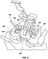
- FIG. 3 is a side view of the virtual jig positioned on a bone according to the embodiment of FIG. 2 ;
- FIG. 4 is a front view of the virtual jig positioned on a bone with corresponding virtual axes of the embodiment of FIG. 2 ;
- FIG. 5 is a side view of the virtual jig positioned on a bone with corresponding virtual axes of the embodiment of FIG. 2 ;
- FIG. 6 is a front view of virtual drill bits superimposed on a grid positioned on a bone
- FIG. 7 is a perspective view of a physical jig secured to a bone
- FIG. 8 is a top view of a grid according to an embodiment of the disclosure.
- FIG. 9 is a top view of another grid according to an embodiment of the disclosure.
- FIG. 10 is a top view of another grid according to an embodiment of the disclosure.
- FIG. 11 is a top view of another grid according to an embodiment of the disclosure.
- FIG. 12 is a top view of another grid according to an embodiment of the disclosure.
- FIG. 13 is a top view of another grid according to an embodiment of the disclosure.
- the terms “virtual,” and “hologram” are used interchangeably, and grammatical equivalents thereof are inclusive or open-ended terms that do not exclude additional, unrecited elements or method steps. These terms are used to describe visual representations of an actual physical device or element, having all, or mostly all, of the same visual characteristics of the physical device, including size and shape.
- Applicant has discovered a novel system and method for generating and using a virtual jig, or virtual instrument, in a surgical procedure, for example, in a knee or tibial implant procedure, or other desired surgical procedure.
- virtual system shall refer broadly to any system capable of generating or creating a simulated or virtual rendering or projection of physical or structural features identical or substantially identical to an actual physical device, instrument or other physical structure, as known in the art.
- a virtual system may also include a device, mechanism, or instrument capable of projecting or displaying the desired a simulated or virtual rendering or projection of physical or structural features identical or substantially identical to an actual physical device.
- a virtual system may also enable a user to manipulate, move and/or modify the simulated or virtual rendering or projection.
- mixed or augmented reality system shall refer broadly to any system capable of generating or creating a simulated or virtual rendering or projection of physical or structural features identical or substantially identical to an actual physical device, instrument or other physical structure, as known in the art.
- a mixed or augmented reality system may also include a device, mechanism, or instrument capable of projecting or displaying the desired a simulated or virtual rendering or projection of physical or structural features identical or substantially identical to an actual physical device overlaid or concurrently with actual physical structures, mechanism or devices in reality, thus incorporating the virtual rendering or projection in real world settings with actual physical element.
- a mixed or augmented reality system may also enable a user to manipulate, move and/or modify the simulated or virtual rendering or projection.
- mixed or augmented reality instrument shall refer broadly to any device, mechanism or instrument used in a mixed or augmented reality system, including a device capable of generating or creating a simulated or virtual rendering or projection of physical or structural features identical or substantially identical to an actual physical device, instrument or other physical structure, as known in the art.
- a mixed or augmented reality instrument may also be capable of projecting or displaying the desired a simulated or virtual rendering or projection of physical or structural features identical or substantially identical to an actual physical device overlaid or concurrently with actual physical structures, mechanism or devices in reality, thus incorporating the virtual rendering or projection in real world settings with actual physical element.
- a mixed or augmented reality instrument may also enable a user to manipulate, move and/or modify the simulated or virtual rendering or projection.
- holographic representation shall refer broadly to a visual rendering or projection representing an actual physical device or element, having all, or mostly all, of the same visual characteristics of the corresponding physical device or element, including size and shape, as known in the art.
- a mixed or augmented system 100 which can be used to produce, or display, a desired mixed or augmented reality instrument, such as a virtual jig or cutting guide in a display to a surgeon or user, or stated another way, that is visible and manipulatable by a surgeon or user.
- the mixed or augmented reality system 100 may also enable a user to activate or deactivate, in full or in part, the virtual instrument or instruments, making a virtual instrument appear or disappear, as desired in a mixed reality assisted surgery, for example.
- the mixed or augmented reality system 100 may include a mixed or augmented reality headset 102 which may include a transparent or mostly transparent viewer 104 which can be suspended or positioned in front of a user's eyes.
- the headset 102 may include headband 106 attached to the viewer 104 , which may be used to secure the headset 102 to a user's head 108 , thereby securing the viewer 104 in place in front of the user's eyes.
- the transparent viewer 104 may be configured to project, or otherwise make viewable, on an interior surface of the viewer 104 , a holographic image or images, such as a virtual jig or cutting guide, which may be positionally manipulated by the user, surgeon, third party or remote system, such as a remote computer system.
- the headset 102 may be configured to view holographic images or, alternatively, the holographic images may be turned off and the user wearing the headset 102 may be able to view the surrounding environment through the transparent viewer 104 , unobstructed.
- a user such as a surgeon for example, can wear the mixed or augmented reality headset 102 and then can choose to activate a holographic image to aide in facilitating a surgical procedure and then shut off the holographic image in order to perform the surgical procedure un-obscured, visually.
- One embodiment of the disclosed headset 102 may be a product created and manufactured by Microsoft, known as the HoloLens® mixed or augmented reality system, or any suitable mixed or augmented reality system for generating virtual images viewable by a user or surgeon.
- Headset 102 may be a conventional “off the shelf” product with a built-in platform that enables all of the features described herein with respect to the headset 102 .
- the headset 102 such as a Microsoft HoloLens product, can be loaded or preloaded with all desired or required virtual instruments, including virtual jigs or surgical cutting guides, virtual drill bits and any other desired virtual instruments or holograms.
- the Microsoft HoloLens product and its capabilities and features, or any suitable mixed or augmented reality system such as is described herein with respect to the headset 102 are known to those skilled in the art.
- a surgeon may use the disclosed method and an embodiment of the disclosed system, to first expose a desired bone 200 or at least a portion of a desired bone 200 to be surgically repaired or to receive a surgical implant. The surgeon may then prepare a surface of the bone, such as cutting a substantially planar surface of the bone, to receive a surgical jig.
- a surgical jig is conventionally, and may be, a surgical tool that may be used to help a surgeon make predetermined and accurate cuts of a desired bone to facilitate attachment of a surgical implant.
- a jig may have one or a series of slots located at specific predetermined locations and at specific predetermined angles, with respect to a body of the jig, such that when the jig is attached to a bone surface, the surgeon can make precise and accurate cuts, using the jig as a guide, without the need of additional measurements.
- the surgeon may attach a grid 300 to the exposed surface of the bone 200 .
- grid shall refer broadly to a platform that may be planar, substantially planar or contoured, and may include a coordinate pattern that may be represented by a physical, visual and/or virtual medium and may include multiple predetermined columns and rows of indicator points, at any desired level of tolerance or spacing between said points, as known in the art, or may include a pattern of indicator points that is not a coordinate pattern or which does not constitute rows and columns, including randomized patterns.
- the general shape of the grid may be any desired shape or size, such as, for example, square, rectangular, circular, triangular, or any other desired shape or configuration.
- the grid may also be made of any desired material, for example, plastic, paper, wax, polyamide, metal, or any other desired material.
- the columns and rows of indicator points may be linear, substantially linear, curved, or the indicator points may be positioned in any desired pattern or randomly positioned without a distinct pattern.
- indicator points shall refer broadly to any visual or physical marker that may be used to identify a specific location on a surface or platform, such as a grid, for example.
- the indicator points may be of any predetermined size or shape.
- the indicator points may be holes that extend through the grid or may be markers visible on a top surface of a grid or other platform or surface.
- Indicator points my include or be represented by numbers, letters, colors, patterns, pictures or drawings, or any other desired visual representation.
- Indicator points may also include physical features such as contours, hills, valleys, grooves, divots, braille, ribs or any other desired physical feature that may be used to identify a specific location on a surface, platform or grid, for example.
- the grid 300 may therefore be attached to an exposed bone that has not been cut, or has been cut already, depending on the needs and desired of the surgeon performing a procedure.
- the grid 300 may include multiple predetermined columns and rows of indicator points 302 , at any desired level of tolerance or spacing between indicator points. These indicator points 302 may for example be equally spaced from one another at predetermined distances.
- the indicator points may also be of a predetermined size, for example, to match a circular diameter of a desired drill bit, attachment pin, or other simply some other desired size or shape.
- the rows and columns of indicator points 302 may essentially form a coordinate pattern on the grid 300 , which can enable a surgeon to locate a virtual jig 400 at a desired location with respect to the bone 200 .
- the grid 300 may also be made of metal, plastic, polyamide or any other desired material.
- pin shall refer broadly to a fastener, stake, staple, rod or other device or mechanism that may pass through at least two objects, releasably securing them together, as known in the art.
- the indicator points 302 may be circular holes, square holes, slots, or formed in any other desired geometric shape.
- the indicator points 302 may be configured of any desired size, for example, indicator points 302 may be configured to receive a 3.2 mm drill bit, or any other desired drill bit size.
- the indicator points 302 may be holes of 3.5 mm diameter, or any other desired diameter or size.
- the grid 300 may be removably fixed or secured to the bone 200 via pins 304 which may be removably inserted through the grid 300 and into the bone 200 .
- the grid 300 may be removably secured or fixed to the bone via some other desired mechanism, such as staples, temporary adhesive, or some other desired attachment mechanism, for example.
- the surgeon may activate the mixed or augmented reality headset 102 , to activate a holographic image, such as the holographic or virtual jig 400 .
- the virtual jig 400 can match the same physical dimensions of a desired physical jig required to make the required bone cuts for engagement with a desired bone implant.
- the headset 102 may be configured with compatible software that can enable the surgeon to pick a desired virtual jig type and size, to match the needs of a patient's bone 200 , and then enable the surgeon to manipulate the positioning of the virtual jig 400 with respect to the bone 200 .
- the surgeon may be able to superimpose the virtual jig over the bone 200 and grid 300 , in a display viewable by the surgeon or user, viewable with the headset 102 .
- the surgeon may also be able to manipulate the virtual jig 400 in that display to achieve a proper desired position with respect to the bone 200 .
- Manipulation of the virtual jig 400 may be accomplished via hand movements of the surgeon, voice activation, or specified key strokes on a linked computer or other compatible electronic device that may be paired and/or electronically linked with the headset 102 .
- the linking between the headset 102 and a remote computer system may be accomplished via WiFi, bluetooth, hardwired or any other desired electronic communication platform or format.
- the compatible software of the mixed or augmented reality headset 102 may also include virtual axes 500 , 502 and 504 (such as x, y and z axes) which may further aid the surgeon in properly and accurately manipulating and positioning the virtual jig 400 .
- the software may further aid the surgeon by changing the color of the corresponding axis 500 , 502 , or 504 when the virtual jig is proper aligned with respect to the bone, for example.
- the software may provide another desired visual indicator when the jig is properly and accurately aligned with respect to the corresponding axes 500 , 502 , and/or 504 .
- the compatible software of the mixed or augmented reality headset 102 may be capable of identifying physical attributes and characteristics of the bone 200 and automatically orient the virtual jig 400 in a proper desired position with respect to the bone 200 . Further, the mixed or augmented reality headset 102 may include virtual representations of potential cutting planes to simulate where and how a cut would be made, given a particular positioning and orientation of the virtual jig 400 or other virtual instrument.
- the virtual jig 400 can be held or anchored in place with respect to the bone.
- the virtual jig 400 at this proper or desired location may be superimposed over the grid 300 .
- the virtual jig 400 may also include at lease one, or multiple, drill holes 402 , which correspond with drill holes in the physical corresponding jig.
- the drill holes 402 may also be superimposed over the grid 300 .
- the surgeon can then locate the coordinates or indicator points 302 that correspond to the drill holes 402 and record the corresponding locations on the grid 300 .
- the surgeon can turn off, hide or otherwise deactivate, in full or at least a portion of, the virtual jig 400 on the viewer 104 of the mixed or augmented reality headset 102 . Then, if desired, the surgeon can activate holographic or virtual drill bits 600 , which can be formed of any desired size or shape, for example.
- the virtual drill bits 600 can also be sized and oriented by the mixed or augmented reality headset 102 and compatible software, to aid and facilitate the surgeon drilling actual physical drill bits or pins into the bone 200 at the proper location on the bone 200 to facilitate the earlier recorded placement of the virtual jig 400 drill holes 402 .
- the compatible software and headset 102 can provide a visual indicator when the drill and drill bit are oriented at the proper angle and location with respect to the bone 200 .
- the compatible software and mixed or augmented reality headset 102 may be preloaded with desired and necessary virtual instruments and/or jigs and corresponding virtual drill bits, or in another example, the corresponding physical drill bits and physical jigs may have self identifying codes or scanable identifiers, such as a QR code (Quick Response) sticker, for example, which can then be used to access the corresponding virtual jig and/or virtual drill bit or pin.
- QR code Quick Response
- the corresponding physical jig 702 can be slipped onto the pins 700 which secure the physical jig 702 into the desired and proper location and orientation with respect to the bone 200 .
- the surgeon will need to deactivate or turn off, in full or at least a portion of, the virtual jig 400 and rely on the identified and recorded coordinates to drill the proper corresponding holes. Without deactivating the virtual jig 400 the surgeon will have significant difficulty making accurate drill holes because the actual drill, drill bit or other required instrument would need to be superimposed over the virtual jig 400 which would then impair the surgeon's view of the precise location and orientation of the proper drill holes.
- the disclosed method of drilling the proper corresponding holes for the actual physical jig 702 avoids this potential inaccuracy, by relying on the coordinates on the grid 300 , which are physical representations and therefore will not be blocked or otherwise impaired when the surgeon makes the required drill holes.
- the physical jig 702 may be made of plastic, metal, polyamide, or any other desired material. Manufacturing the physical jig 702 out of a plastic or polyamide material, or other relatively inexpensive material, may allow the physical jig 702 to be disposable, while still maintaining the precision and accuracy of traditional metal jigs.
- the physical jig 702 may also be manufactured using a 3D printer, which can further reduce the cost of manufacturing and storage of jigs, since 3D printed jigs could be made on demand, customized to the size and shape required by individual patients and users.
- the physical jig 702 may also be manufactured using any other known technique for forming a physical jig.
- the compatible and the corresponding locations and orientations of the virtual drill bits 600 may be activated on the virtual headset 102 after at least a portion of the virtual jig 400 has been deactivated. Because the virtual drill bits 600 may have the same geometric and physical attributes as the actual physical drill bits 700 , the surgeon may use the virtual drill bits 600 as a drilling guide of the actual physical drill bits without risking inaccuracy due to any potential interference between the virtual drill bits 600 and the physical drill bits 700 , during drilling of the actual physical drill bits.
- the surgeon may attach a grid 800 to the exposed surface of a bone, as similarly done with respect to grid 300 disclosed above. Therefore, the grid 800 may be attached to an exposed bone that has not been cut, or has been cut already, depending on the needs and desired of the surgeon performing a procedure.
- the grid 800 may include multiple predetermined columns and rows of indicator points 802 , at any desired level of tolerance or spacing between grid holes. These indicator points 802 may for example be equally spaced from one another at predetermined distances.
- the indicator points 802 may also be of a predetermined size, for example, to match a circular diameter of a desired drill bit, attachment pin, or other simply some other desired size or shape.
- the rows and columns of indicator points 802 may essentially form a coordinate pattern on the grid 800 , which can enable a surgeon to locate a virtual jig 400 at a desired location with respect to a bone.
- each indicator point may be centered within a square 804 or 806 which may have structural features that alternate square 804 to square 806 , ti enable a surgeon or user to better visualize the coordinate pattern on the grid 800 .
- squares 804 may be white in color and squares 806 may be black in color, or squares 804 and 806 can be any other contrasting colors, which can further improve the visual identification of the coordinate pattern.
- Squares 804 may also have a raised surface with respect to adjacent square 806 , which may include a sunken surface or counterbored surface, for example, which also can further improve the visual identification of the coordinate pattern.
- adjacent squares 804 and 806 may also be utilized by the headset 102 during spatial mapping, to facilitate identification and positioning of three dimensional vectors for virtual jigs 400 and/or virtual drill bits.
- Each of the squares 804 and 806 may be of any desired size to accommodate the corresponding indicator points 802 , for example, each square may have 5.5 mm sides, or any other desired size.
- the squares 804 and 806 may also be formed in any desired shape, such as rectangular, triangular or any other desired shape.
- the grid 800 may also be made of metal, plastic, polyamide or any other desired material.
- the indicator points 802 may be circular holes, square holes, slots, or formed in any other desired geometric shape.
- the indicator points 802 may be configured of any desired size, for example, indicator points 302 may be configured to receive a 3.2 mm drill bit, or any other desired drill bit size. In another example, the indicator points 302 may be holes of 3.5 mm diameter, or any other desired diameter or size.
- the grid 800 may be removably fixed or secured to a bone via pins (not shown) which may be removably inserted through the grid 800 at predetermined holes 808 and into the adjoining bone.
- the grid 800 may be removably secured or fixed to the bone via some other desired mechanism, such as staples, temporary adhesive, or some other desired attachment mechanism, for example.
- FIG. 9 illustrates another embodiment which includes a grid 900 which may be used in the same way described with respect to grid 800 above.
- a surgeon may attach grid 900 to an exposed surface of a bone, as similarly done with respect to grids 300 and 800 disclosed above.
- the grid 900 may be formed in a substantially circular shape, or any other desired shape, and include a series of indicator points 902 , at any desired level of tolerance or spacing between adjacent indicator points 902 .
- These indicator points 902 may be position in substantially concentric circular patterns, as shown in FIG. 9 , or in any other desired pattern.
- the indicator points 902 may be holes or visual markers and may be of any predetermined size, for example, to match a circular diameter of a desired drill bit, attachment pin, or other any other desired size or shape.
- FIG. 10 illustrates another embodiment which includes a grid 1000 which may be used in the same way described with respect to grid 800 above.
- a surgeon may attach grid 1000 to an exposed surface of a bone, as similarly done with respect to grids 300 and 800 disclosed above.
- the grid 1000 may be formed in a substantially triangular shape, or any other desired shape, and include a series of indicator points 1002 , at any desired level of tolerance or spacing between adjacent indicator points 1002 .
- These indicator points 1002 may be position in substantially in a random pattern, as shown in FIG. 10 , or in any other desired pattern.
- the indicator points 1002 may be “x”s, holes or other desired visual markers and may be of any predetermined size, for example, to match a circular diameter of a desired drill bit, attachment pin, or other any other desired size or shape.
- FIG. 11 illustrates another embodiment which includes a grid 1100 which may be used in the same way described with respect to grid 800 above.
- a surgeon may attach grid 1100 to an exposed surface of a bone, as similarly done with respect to grids 300 and 800 disclosed above.
- the grid 1100 may be formed in a substantially rectangular shape, or any other desired shape, and include a series of indicator points 1102 , at any desired level of tolerance or spacing between adjacent indicator points 1102 . These indicator points 1102 may be position in substantially in rows and columns, as shown in FIG. 11 , or in any other desired pattern.
- the indicator points 1102 may be numbers, holes or other desired visual markers and may be of any predetermined size, for example, to match a circular diameter of a desired drill bit, attachment pin, or other any other desired size or shape.
- FIG. 12 illustrates another embodiment which includes a grid 1100 which may be used in the same way described with respect to grid 800 above.
- a surgeon may attach grid 1200 to an exposed surface of a bone, as similarly done with respect to grids 300 and 800 disclosed above.
- the grid 1200 may be formed in a substantially rectangular shape, or any other desired shape, and include a series of indicator points 1202 , at any desired level of tolerance or spacing between adjacent indicator points 1202 . These indicator points 1202 may be position in substantially in rows and columns, as shown in FIG. 12 , or in any other desired pattern.
- the indicator points 1202 may be letters, holes or other desired visual markers and may be of any predetermined size, for example, to match a circular diameter of a desired drill bit, attachment pin, or other any other desired size or shape.
- FIG. 13 illustrates another embodiment which includes a grid 1300 which may be used in the same way described with respect to grid 800 above.
- a surgeon may attach grid 1300 to an exposed surface of a bone, as similarly done with respect to grids 300 and 800 disclosed above.
- the grid 1300 may be formed in a substantially rectangular shape, or any other desired shape, and include a series of indicator points 1302 , at any desired level of tolerance or spacing between adjacent indicator points 1302 .
- These indicator points 1302 may be position in substantially in rows and columns, as shown in FIG. 13 , or in any other desired pattern.
- the indicator points 1302 may be contours, hills and valleys, or other desired visual or physical markers and may be of any predetermined size.
- the compatible software and mixed or augmented reality headset 102 may provide the surgeon with holographic or virtual rulers or measurement devices, which can be used and manipulated by the surgeon to measure physical features of the bone, such as medial or later side of the bone, or knee for example, to determine where initial cuts to the bone should be made, such as initial cuts to a femur or tibial in a knee replacement procedure, for example.
- These virtual measurement devices may also aid a surgeon in confirming proper orientation of the virtual jig 400 with respect the bone.
- the compatible software and mixed or augmented reality headset 102 may enable a surgeon or user to make other surgical procedure on various parts and bone of a body, using similar methodology as provided above with respect to a virtual and actual jig, utilizing a grid similar to the disclosed grid 300 , and following the same substantive steps of activating and deactivating the virtual jig (or other desired instrument), and relying on the coordinates of the grid 300 .
- the disclosed system and method of utilizing a virtual instrument superimposed over a physical grid to identify and record the desired orientation and positioning of an actual physical instrument may be useful in other non-analogous fields, such as wall decor and placement, domestic and industrial construction projects, or any other desired filed of use.
Landscapes
- Engineering & Computer Science (AREA)
- Health & Medical Sciences (AREA)
- Physics & Mathematics (AREA)
- Surgery (AREA)
- Life Sciences & Earth Sciences (AREA)
- General Physics & Mathematics (AREA)
- Software Systems (AREA)
- Computer Graphics (AREA)
- Theoretical Computer Science (AREA)
- General Engineering & Computer Science (AREA)
- Computer Hardware Design (AREA)
- Robotics (AREA)
- Medical Informatics (AREA)
- Animal Behavior & Ethology (AREA)
- General Health & Medical Sciences (AREA)
- Public Health (AREA)
- Veterinary Medicine (AREA)
- Nuclear Medicine, Radiotherapy & Molecular Imaging (AREA)
- Molecular Biology (AREA)
- Heart & Thoracic Surgery (AREA)
- Biomedical Technology (AREA)
- Optics & Photonics (AREA)
- Architecture (AREA)
- Radar, Positioning & Navigation (AREA)
- Remote Sensing (AREA)
- Surgical Instruments (AREA)
- Prostheses (AREA)
Abstract
Description
Claims (22)
Priority Applications (1)
| Application Number | Priority Date | Filing Date | Title |
|---|---|---|---|
| US16/788,198 US11045263B1 (en) | 2019-12-16 | 2020-02-11 | System and method for generating a virtual jig for surgical procedures |
Applications Claiming Priority (2)
| Application Number | Priority Date | Filing Date | Title |
|---|---|---|---|
| US201962948760P | 2019-12-16 | 2019-12-16 | |
| US16/788,198 US11045263B1 (en) | 2019-12-16 | 2020-02-11 | System and method for generating a virtual jig for surgical procedures |
Publications (2)
| Publication Number | Publication Date |
|---|---|
| US20210177521A1 US20210177521A1 (en) | 2021-06-17 |
| US11045263B1 true US11045263B1 (en) | 2021-06-29 |
Family
ID=76316596
Family Applications (1)
| Application Number | Title | Priority Date | Filing Date |
|---|---|---|---|
| US16/788,198 Active US11045263B1 (en) | 2019-12-16 | 2020-02-11 | System and method for generating a virtual jig for surgical procedures |
Country Status (1)
| Country | Link |
|---|---|
| US (1) | US11045263B1 (en) |
Cited By (4)
| Publication number | Priority date | Publication date | Assignee | Title |
|---|---|---|---|---|
| US11571225B2 (en) | 2020-08-17 | 2023-02-07 | Russell Todd Nevins | System and method for location determination using movement between optical labels and a 3D spatial mapping camera |
| US11600053B1 (en) | 2021-10-04 | 2023-03-07 | Russell Todd Nevins | System and method for location determination using a mixed reality device and multiple imaging cameras |
| US11806081B2 (en) | 2021-04-02 | 2023-11-07 | Russell Todd Nevins | System and method for location determination using movement of an optical label fixed to a bone using a spatial mapping camera |
| US12236536B2 (en) | 2020-08-17 | 2025-02-25 | Russell Todd Nevins | System and method for location determination using a mixed reality device and a 3D spatial mapping camera |
Citations (23)
| Publication number | Priority date | Publication date | Assignee | Title |
|---|---|---|---|---|
| US20080183179A1 (en) | 2004-05-22 | 2008-07-31 | Thomas Siebel | Surgical Jig |
| US20090163923A1 (en) | 2004-02-27 | 2009-06-25 | Magnus Flett | Surgical jig and methods of use |
| US7812815B2 (en) | 2005-01-25 | 2010-10-12 | The Broad of Trustees of the University of Illinois | Compact haptic and augmented virtual reality system |
| US8876830B2 (en) | 2009-08-13 | 2014-11-04 | Zimmer, Inc. | Virtual implant placement in the OR |
| US8954181B2 (en) | 2010-12-07 | 2015-02-10 | Sirona Dental Systems Gmbh | Systems, methods, apparatuses, and computer-readable storage media for designing and manufacturing custom dental preparation guides |
| US8956165B2 (en) | 2008-01-25 | 2015-02-17 | University Of Florida Research Foundation, Inc. | Devices and methods for implementing endoscopic surgical procedures and instruments within a virtual environment |
| US20160191887A1 (en) | 2014-12-30 | 2016-06-30 | Carlos Quiles Casas | Image-guided surgery with surface reconstruction and augmented reality visualization |
| US9563266B2 (en) | 2012-09-27 | 2017-02-07 | Immersivetouch, Inc. | Haptic augmented and virtual reality system for simulation of surgical procedures |
| US9730713B2 (en) | 2002-05-15 | 2017-08-15 | Howmedica Osteonics Corporation | Arthroplasty jig |
| US20170245781A1 (en) | 2016-02-29 | 2017-08-31 | Extremity Development Company, Llc | Smart drill, jig, and method of orthopedic surgery |
| US9861446B2 (en) | 2016-03-12 | 2018-01-09 | Philipp K. Lang | Devices and methods for surgery |
| US20180090029A1 (en) | 2016-09-29 | 2018-03-29 | Simbionix Ltd. | Method and system for medical simulation in an operating room in a virtual reality or augmented reality environment |
| US20180098813A1 (en) | 2016-10-07 | 2018-04-12 | Simbionix Ltd. | Method and system for rendering a medical simulation in an operating room in virtual reality or augmented reality environment |
| WO2018132804A1 (en) * | 2017-01-16 | 2018-07-19 | Lang Philipp K | Optical guidance for surgical, medical, and dental procedures |
| US10108266B2 (en) | 2012-09-27 | 2018-10-23 | The Board Of Trustees Of The University Of Illinois | Haptic augmented and virtual reality system for simulation of surgical procedures |
| US10194990B2 (en) | 2016-04-27 | 2019-02-05 | Arthrology Consulting, Llc | Method for augmenting a surgical field with virtual guidance content |
| US10220181B2 (en) | 2014-03-06 | 2019-03-05 | Virtual Reality Medical Applications, Inc | Virtual reality medical application system |
| US20190076198A1 (en) * | 2017-09-12 | 2019-03-14 | Michael E. Berend | Femoral medial condyle spherical center tracking |
| US10241569B2 (en) | 2015-12-08 | 2019-03-26 | Facebook Technologies, Llc | Focus adjustment method for a virtual reality headset |
| US10285765B2 (en) | 2014-05-05 | 2019-05-14 | Vicarious Surgical Inc. | Virtual reality surgical device |
| US10401954B2 (en) | 2017-04-17 | 2019-09-03 | Intel Corporation | Sensory enhanced augmented reality and virtual reality device |
| US10405873B2 (en) | 2006-08-03 | 2019-09-10 | Orthosoft Ulc | Computer-assisted surgery tools and system |
| US10437335B2 (en) | 2015-04-14 | 2019-10-08 | John James Daniels | Wearable electronic, multi-sensory, human/machine, human/human interfaces |
-
2020
- 2020-02-11 US US16/788,198 patent/US11045263B1/en active Active
Patent Citations (36)
| Publication number | Priority date | Publication date | Assignee | Title |
|---|---|---|---|---|
| US9730713B2 (en) | 2002-05-15 | 2017-08-15 | Howmedica Osteonics Corporation | Arthroplasty jig |
| US20090163923A1 (en) | 2004-02-27 | 2009-06-25 | Magnus Flett | Surgical jig and methods of use |
| US8123754B2 (en) | 2004-05-22 | 2012-02-28 | Depuy International Ltd. | Surgical jig |
| US20080183179A1 (en) | 2004-05-22 | 2008-07-31 | Thomas Siebel | Surgical Jig |
| US7812815B2 (en) | 2005-01-25 | 2010-10-12 | The Broad of Trustees of the University of Illinois | Compact haptic and augmented virtual reality system |
| US10405873B2 (en) | 2006-08-03 | 2019-09-10 | Orthosoft Ulc | Computer-assisted surgery tools and system |
| US8956165B2 (en) | 2008-01-25 | 2015-02-17 | University Of Florida Research Foundation, Inc. | Devices and methods for implementing endoscopic surgical procedures and instruments within a virtual environment |
| US8876830B2 (en) | 2009-08-13 | 2014-11-04 | Zimmer, Inc. | Virtual implant placement in the OR |
| US8954181B2 (en) | 2010-12-07 | 2015-02-10 | Sirona Dental Systems Gmbh | Systems, methods, apparatuses, and computer-readable storage media for designing and manufacturing custom dental preparation guides |
| US20180348876A1 (en) | 2012-09-27 | 2018-12-06 | The Board Of Trustees Of The University Of Illinois | Haptic augmented and virtual reality system for simulation of surgical procedures |
| US10437339B2 (en) | 2012-09-27 | 2019-10-08 | The Board Of Trustees Of The University Of Illinois | Haptic augmented and virtual reality system for simulation of surgical procedures |
| US10108266B2 (en) | 2012-09-27 | 2018-10-23 | The Board Of Trustees Of The University Of Illinois | Haptic augmented and virtual reality system for simulation of surgical procedures |
| US9563266B2 (en) | 2012-09-27 | 2017-02-07 | Immersivetouch, Inc. | Haptic augmented and virtual reality system for simulation of surgical procedures |
| US10220181B2 (en) | 2014-03-06 | 2019-03-05 | Virtual Reality Medical Applications, Inc | Virtual reality medical application system |
| US10286179B2 (en) | 2014-03-06 | 2019-05-14 | Virtual Reality Medical Applications, Inc | Virtual reality medical application system |
| US20190216562A1 (en) | 2014-05-05 | 2019-07-18 | Vicarious Surgical Inc. | Virtual reality surgical device |
| US10285765B2 (en) | 2014-05-05 | 2019-05-14 | Vicarious Surgical Inc. | Virtual reality surgical device |
| US20160191887A1 (en) | 2014-12-30 | 2016-06-30 | Carlos Quiles Casas | Image-guided surgery with surface reconstruction and augmented reality visualization |
| US10437335B2 (en) | 2015-04-14 | 2019-10-08 | John James Daniels | Wearable electronic, multi-sensory, human/machine, human/human interfaces |
| US10241569B2 (en) | 2015-12-08 | 2019-03-26 | Facebook Technologies, Llc | Focus adjustment method for a virtual reality headset |
| US20170245781A1 (en) | 2016-02-29 | 2017-08-31 | Extremity Development Company, Llc | Smart drill, jig, and method of orthopedic surgery |
| US10278777B1 (en) | 2016-03-12 | 2019-05-07 | Philipp K. Lang | Augmented reality visualization for guiding bone cuts including robotics |
| US10159530B2 (en) | 2016-03-12 | 2018-12-25 | Philipp K. Lang | Guidance for surgical interventions |
| US20190110842A1 (en) | 2016-03-12 | 2019-04-18 | Philipp K. Lang | Augmented Reality Visualization for Guiding Bone Cuts Including Robotics |
| US10405927B1 (en) | 2016-03-12 | 2019-09-10 | Philipp K. Lang | Augmented reality visualization for guiding physical surgical tools and instruments including robotics |
| US9980780B2 (en) | 2016-03-12 | 2018-05-29 | Philipp K. Lang | Guidance for surgical procedures |
| US20180116728A1 (en) | 2016-03-12 | 2018-05-03 | Philipp K. Lang | Novel guidance for surgical procedures |
| US10292768B2 (en) | 2016-03-12 | 2019-05-21 | Philipp K. Lang | Augmented reality guidance for articular procedures |
| US10368947B2 (en) | 2016-03-12 | 2019-08-06 | Philipp K. Lang | Augmented reality guidance systems for superimposing virtual implant components onto the physical joint of a patient |
| US9861446B2 (en) | 2016-03-12 | 2018-01-09 | Philipp K. Lang | Devices and methods for surgery |
| US10194990B2 (en) | 2016-04-27 | 2019-02-05 | Arthrology Consulting, Llc | Method for augmenting a surgical field with virtual guidance content |
| US20180090029A1 (en) | 2016-09-29 | 2018-03-29 | Simbionix Ltd. | Method and system for medical simulation in an operating room in a virtual reality or augmented reality environment |
| US20180098813A1 (en) | 2016-10-07 | 2018-04-12 | Simbionix Ltd. | Method and system for rendering a medical simulation in an operating room in virtual reality or augmented reality environment |
| WO2018132804A1 (en) * | 2017-01-16 | 2018-07-19 | Lang Philipp K | Optical guidance for surgical, medical, and dental procedures |
| US10401954B2 (en) | 2017-04-17 | 2019-09-03 | Intel Corporation | Sensory enhanced augmented reality and virtual reality device |
| US20190076198A1 (en) * | 2017-09-12 | 2019-03-14 | Michael E. Berend | Femoral medial condyle spherical center tracking |
Non-Patent Citations (12)
| Title |
|---|
| Barad, Justin, Virtual and Augmented Reality Can Save Lives by Improving Surgeons' Training, retrieved at https://www.statnews.com/2019/08/16/virtual-reality-improve-surgeon-training, dated Aug. 16, 2019. |
| Daley, Sam, The Cutting Edge: 10 Companies Bringing Virtual Reality & AR to the OR, retrieved at https://builtin.com/healthcare-technology/augmented-virtual-reality-surgery, dated Jul. 5, 2019. |
| Immersive Touch Launches the First Virtual Reality Integrated Suite for Surgical Planning, retrieved at https://spinalnewsinternational.com/immersivetouch-virtual-reality-suite, dated Oct. 5, 2018. |
| Kaluschke et al., HIPS—A Virtual Reality Hip Prosthesis Implantation Simulator, retrieved at https://www.reasearchgate.net/publication/327329265, upload date Sep. 3, 2018 DOI: 10.1109/VR.2018.8446370. |
| Levin et al., The Future of Virtual Reality in Ophthalmology Is Already Here, retrieved at https://www.aao.org/young-ophthalmologists/yo-info/article/future-of-virtual-reality-in-ophthalmology, dated Aug. 16, 2019. |
| LexInnova Patent Landscape Analysis, Virtual Reality, unknown author, copyright date of 2015. |
| Microsoft HoloLens & Mixed /Reality Healthcare Industry Deck, unknown author, at least as early as Oct. 14, 2019. |
| Patently Apple—Apple Reveals a Mixed Reality Headset that Uses a Direct Retinal Projector System With Holographic Lenses, retrieved at https://www.patentlyapple.com/patently-apple/2019/09/apple-reveals-a-mixed-reality-headset-that-uses-a-direct-retinal-projector-system-with-hologra . . . ; posted date Sep. 19, 2019. |
| Vaughan et al., A Review of Virtual Reality Based Training Simulators for Orthopaedic Surgery, retrieved at https://www.researchgate.net/publication/283727217, posted date Feb. 22, 2019, DOI: 10.1016/j.medengphy.2015.11.021. |
| Vaughan et al., Does Virtual-Reality Training on Orthopaedic Simulators Improve Performance in the Operating Room? Science and Information Conference 2015, Jul. 28-30, 2015, London, UK; retrieved at https://www.researchgate.net/publication/284415791; DOI: 10.1109/SAI.2015.7237125. |
| Virtual & Augmented Reality Are You Sure it Isn't Real? Kathleen Boyle, CFA, Managing Editor, Citi GPS dated Oct. 2016. |
| Virtual Reality System Helps Surgeons, Reassures Patients, retrieved at https//medicalgiving.stanford.edu/news/virtual-reality-system-helps-surgeons-reassures-patients.html, retrieved date Oct. 24, 2019. |
Cited By (7)
| Publication number | Priority date | Publication date | Assignee | Title |
|---|---|---|---|---|
| US11571225B2 (en) | 2020-08-17 | 2023-02-07 | Russell Todd Nevins | System and method for location determination using movement between optical labels and a 3D spatial mapping camera |
| US12236536B2 (en) | 2020-08-17 | 2025-02-25 | Russell Todd Nevins | System and method for location determination using a mixed reality device and a 3D spatial mapping camera |
| US12290271B2 (en) | 2020-08-17 | 2025-05-06 | Russell Todd Nevins | System and method for location determination using movement between optical labels and a 3D spatial mapping camera |
| US11806081B2 (en) | 2021-04-02 | 2023-11-07 | Russell Todd Nevins | System and method for location determination using movement of an optical label fixed to a bone using a spatial mapping camera |
| US11871997B2 (en) | 2021-04-02 | 2024-01-16 | Russell Todd Nevins | System and method for location determination using movement of an optical label fixed to a bone using a spatial mapping camera |
| US11600053B1 (en) | 2021-10-04 | 2023-03-07 | Russell Todd Nevins | System and method for location determination using a mixed reality device and multiple imaging cameras |
| US11610378B1 (en) | 2021-10-04 | 2023-03-21 | Russell Todd Nevins | System and method for location determination using a mixed reality device and multiple imaging cameras |
Also Published As
| Publication number | Publication date |
|---|---|
| US20210177521A1 (en) | 2021-06-17 |
Similar Documents
| Publication | Publication Date | Title |
|---|---|---|
| US11045263B1 (en) | System and method for generating a virtual jig for surgical procedures | |
| US12236536B2 (en) | System and method for location determination using a mixed reality device and a 3D spatial mapping camera | |
| US20250107856A1 (en) | System and method for computer-aided surgical navigation implementing 3d scans | |
| KR102378417B1 (en) | METHODS AND DEVICES FOR KNEE SURGERY WITH INERTIAL SENSORS | |
| US10136901B2 (en) | Anatomical concentric spheres THA | |
| US11571225B2 (en) | System and method for location determination using movement between optical labels and a 3D spatial mapping camera | |
| AU2025220774A1 (en) | Robotic surgery system for augmented hip arthroplasty procedures | |
| EP3435922B1 (en) | Bone model for trialing a medical implant | |
| AU2004200326A1 (en) | Universal alignment guide | |
| CA2939934A1 (en) | Acetabular cup impacting using patient-specific instrumentation | |
| US20100106253A1 (en) | Prosthetic joint component planning template | |
| US8926627B2 (en) | Apparatus and method for transferring predetermined spatial positioning information to an adjustable tool | |
| CN104519808A (en) | A system for preoperative planning and patient-specific surgical assistance | |
| US11610378B1 (en) | System and method for location determination using a mixed reality device and multiple imaging cameras | |
| US11806081B2 (en) | System and method for location determination using movement of an optical label fixed to a bone using a spatial mapping camera | |
| US20240221325A1 (en) | System and method for location determination using a virtual alignment target |
Legal Events
| Date | Code | Title | Description |
|---|---|---|---|
| FEPP | Fee payment procedure |
Free format text: ENTITY STATUS SET TO UNDISCOUNTED (ORIGINAL EVENT CODE: BIG.); ENTITY STATUS OF PATENT OWNER: SMALL ENTITY |
|
| FEPP | Fee payment procedure |
Free format text: ENTITY STATUS SET TO SMALL (ORIGINAL EVENT CODE: SMAL); ENTITY STATUS OF PATENT OWNER: SMALL ENTITY |
|
| AS | Assignment |
Owner name: NEVINS, RUSSELL, NEVADA Free format text: ASSIGNMENT OF ASSIGNORS INTEREST;ASSIGNORS:NEVINS, RUSSELL;BACKSTEIN, DAVID JON;NATHAN, BRADLEY H.;SIGNING DATES FROM 20200207 TO 20200722;REEL/FRAME:053298/0505 Owner name: BACKSTEIN, DAVID JON, ONTARIO Free format text: ASSIGNMENT OF ASSIGNORS INTEREST;ASSIGNORS:NEVINS, RUSSELL;BACKSTEIN, DAVID JON;NATHAN, BRADLEY H.;SIGNING DATES FROM 20200207 TO 20200722;REEL/FRAME:053298/0505 Owner name: NATHAN, BRADLEY H., ONTARIO Free format text: ASSIGNMENT OF ASSIGNORS INTEREST;ASSIGNORS:NEVINS, RUSSELL;BACKSTEIN, DAVID JON;NATHAN, BRADLEY H.;SIGNING DATES FROM 20200207 TO 20200722;REEL/FRAME:053298/0505 |
|
| STCF | Information on status: patent grant |
Free format text: PATENTED CASE |
|
| FEPP | Fee payment procedure |
Free format text: MAINTENANCE FEE REMINDER MAILED (ORIGINAL EVENT CODE: REM.); ENTITY STATUS OF PATENT OWNER: SMALL ENTITY |
|
| FEPP | Fee payment procedure |
Free format text: SURCHARGE FOR LATE PAYMENT, SMALL ENTITY (ORIGINAL EVENT CODE: M2554); ENTITY STATUS OF PATENT OWNER: SMALL ENTITY |
|
| MAFP | Maintenance fee payment |
Free format text: PAYMENT OF MAINTENANCE FEE, 4TH YR, SMALL ENTITY (ORIGINAL EVENT CODE: M2551); ENTITY STATUS OF PATENT OWNER: SMALL ENTITY Year of fee payment: 4 |