US11045240B2 - Dispensing system and method - Google Patents
Dispensing system and method Download PDFInfo
- Publication number
- US11045240B2 US11045240B2 US16/437,345 US201916437345A US11045240B2 US 11045240 B2 US11045240 B2 US 11045240B2 US 201916437345 A US201916437345 A US 201916437345A US 11045240 B2 US11045240 B2 US 11045240B2
- Authority
- US
- United States
- Prior art keywords
- chamber
- proximal
- distal
- plunger
- opening
- Prior art date
- Legal status (The legal status is an assumption and is not a legal conclusion. Google has not performed a legal analysis and makes no representation as to the accuracy of the status listed.)
- Active, expires
Links
Images


Classifications
-
- A—HUMAN NECESSITIES
- A61—MEDICAL OR VETERINARY SCIENCE; HYGIENE
- A61B—DIAGNOSIS; SURGERY; IDENTIFICATION
- A61B17/00—Surgical instruments, devices or methods
- A61B17/56—Surgical instruments or methods for treatment of bones or joints; Devices specially adapted therefor
- A61B17/58—Surgical instruments or methods for treatment of bones or joints; Devices specially adapted therefor for osteosynthesis, e.g. bone plates, screws or setting implements
- A61B17/88—Osteosynthesis instruments; Methods or means for implanting or extracting internal or external fixation devices
- A61B17/8802—Equipment for handling bone cement or other fluid fillers
- A61B17/8833—Osteosynthesis tools specially adapted for handling bone cement or fluid fillers; Means for supplying bone cement or fluid fillers to introducing tools, e.g. cartridge handling means
-
- A—HUMAN NECESSITIES
- A61—MEDICAL OR VETERINARY SCIENCE; HYGIENE
- A61B—DIAGNOSIS; SURGERY; IDENTIFICATION
- A61B17/00—Surgical instruments, devices or methods
- A61B17/56—Surgical instruments or methods for treatment of bones or joints; Devices specially adapted therefor
- A61B17/58—Surgical instruments or methods for treatment of bones or joints; Devices specially adapted therefor for osteosynthesis, e.g. bone plates, screws or setting implements
- A61B17/88—Osteosynthesis instruments; Methods or means for implanting or extracting internal or external fixation devices
- A61B17/8802—Equipment for handling bone cement or other fluid fillers
- A61B17/8805—Equipment for handling bone cement or other fluid fillers for introducing fluid filler into bone or extracting it
- A61B17/8816—Equipment for handling bone cement or other fluid fillers for introducing fluid filler into bone or extracting it characterised by the conduit, e.g. tube, along which fluid flows into the body or by conduit connections
-
- A—HUMAN NECESSITIES
- A61—MEDICAL OR VETERINARY SCIENCE; HYGIENE
- A61B—DIAGNOSIS; SURGERY; IDENTIFICATION
- A61B17/00—Surgical instruments, devices or methods
- A61B17/56—Surgical instruments or methods for treatment of bones or joints; Devices specially adapted therefor
- A61B17/58—Surgical instruments or methods for treatment of bones or joints; Devices specially adapted therefor for osteosynthesis, e.g. bone plates, screws or setting implements
- A61B17/88—Osteosynthesis instruments; Methods or means for implanting or extracting internal or external fixation devices
- A61B17/8802—Equipment for handling bone cement or other fluid fillers
- A61B17/8805—Equipment for handling bone cement or other fluid fillers for introducing fluid filler into bone or extracting it
- A61B17/8822—Equipment for handling bone cement or other fluid fillers for introducing fluid filler into bone or extracting it characterised by means facilitating expulsion of fluid from the introducer, e.g. a screw pump plunger, hydraulic force transmissions, application of vibrations or a vacuum
-
- A—HUMAN NECESSITIES
- A61—MEDICAL OR VETERINARY SCIENCE; HYGIENE
- A61B—DIAGNOSIS; SURGERY; IDENTIFICATION
- A61B17/00—Surgical instruments, devices or methods
- A61B17/56—Surgical instruments or methods for treatment of bones or joints; Devices specially adapted therefor
- A61B17/58—Surgical instruments or methods for treatment of bones or joints; Devices specially adapted therefor for osteosynthesis, e.g. bone plates, screws or setting implements
- A61B17/88—Osteosynthesis instruments; Methods or means for implanting or extracting internal or external fixation devices
- A61B17/8802—Equipment for handling bone cement or other fluid fillers
- A61B17/8805—Equipment for handling bone cement or other fluid fillers for introducing fluid filler into bone or extracting it
- A61B17/8825—Equipment for handling bone cement or other fluid fillers for introducing fluid filler into bone or extracting it characterised by syringe details
-
- B01F15/0223—
-
- B01F15/0237—
-
- B01F15/0416—
-
- B—PERFORMING OPERATIONS; TRANSPORTING
- B01—PHYSICAL OR CHEMICAL PROCESSES OR APPARATUS IN GENERAL
- B01F—MIXING, e.g. DISSOLVING, EMULSIFYING OR DISPERSING
- B01F23/00—Mixing according to the phases to be mixed, e.g. dispersing or emulsifying
- B01F23/40—Mixing liquids with liquids; Emulsifying
- B01F23/45—Mixing liquids with liquids; Emulsifying using flow mixing
-
- B—PERFORMING OPERATIONS; TRANSPORTING
- B01—PHYSICAL OR CHEMICAL PROCESSES OR APPARATUS IN GENERAL
- B01F—MIXING, e.g. DISSOLVING, EMULSIFYING OR DISPERSING
- B01F23/00—Mixing according to the phases to be mixed, e.g. dispersing or emulsifying
- B01F23/40—Mixing liquids with liquids; Emulsifying
- B01F23/47—Mixing liquids with liquids; Emulsifying involving high-viscosity liquids, e.g. asphalt
-
- B—PERFORMING OPERATIONS; TRANSPORTING
- B01—PHYSICAL OR CHEMICAL PROCESSES OR APPARATUS IN GENERAL
- B01F—MIXING, e.g. DISSOLVING, EMULSIFYING OR DISPERSING
- B01F25/00—Flow mixers; Mixers for falling materials, e.g. solid particles
- B01F25/40—Static mixers
- B01F25/42—Static mixers in which the mixing is affected by moving the components jointly in changing directions, e.g. in tubes provided with baffles or obstructions
- B01F25/43—Mixing tubes, e.g. wherein the material is moved in a radial or partly reversed direction
- B01F25/431—Straight mixing tubes with baffles or obstructions that do not cause substantial pressure drop; Baffles therefor
- B01F25/4314—Straight mixing tubes with baffles or obstructions that do not cause substantial pressure drop; Baffles therefor with helical baffles
- B01F25/43141—Straight mixing tubes with baffles or obstructions that do not cause substantial pressure drop; Baffles therefor with helical baffles composed of consecutive sections of helical formed elements
-
- B01F3/0861—
-
- B01F3/10—
-
- B—PERFORMING OPERATIONS; TRANSPORTING
- B01—PHYSICAL OR CHEMICAL PROCESSES OR APPARATUS IN GENERAL
- B01F—MIXING, e.g. DISSOLVING, EMULSIFYING OR DISPERSING
- B01F35/00—Accessories for mixers; Auxiliary operations or auxiliary devices; Parts or details of general application
- B01F35/71—Feed mechanisms
- B01F35/716—Feed mechanisms characterised by the relative arrangement of the containers for feeding or mixing the components
- B01F35/7161—Feed mechanisms characterised by the relative arrangement of the containers for feeding or mixing the components the containers being connected coaxially before contacting the contents
-
- B—PERFORMING OPERATIONS; TRANSPORTING
- B01—PHYSICAL OR CHEMICAL PROCESSES OR APPARATUS IN GENERAL
- B01F—MIXING, e.g. DISSOLVING, EMULSIFYING OR DISPERSING
- B01F35/00—Accessories for mixers; Auxiliary operations or auxiliary devices; Parts or details of general application
- B01F35/71—Feed mechanisms
- B01F35/717—Feed mechanisms characterised by the means for feeding the components to the mixer
- B01F35/7174—Feed mechanisms characterised by the means for feeding the components to the mixer using pistons, plungers or syringes
-
- B—PERFORMING OPERATIONS; TRANSPORTING
- B01—PHYSICAL OR CHEMICAL PROCESSES OR APPARATUS IN GENERAL
- B01F—MIXING, e.g. DISSOLVING, EMULSIFYING OR DISPERSING
- B01F35/00—Accessories for mixers; Auxiliary operations or auxiliary devices; Parts or details of general application
- B01F35/80—Forming a predetermined ratio of the substances to be mixed
- B01F35/83—Forming a predetermined ratio of the substances to be mixed by controlling the ratio of two or more flows, e.g. using flow sensing or flow controlling devices
- B01F35/831—Forming a predetermined ratio of the substances to be mixed by controlling the ratio of two or more flows, e.g. using flow sensing or flow controlling devices using one or more pump or other dispensing mechanisms for feeding the flows in predetermined proportion, e.g. one of the pumps being driven by one of the flows
-
- B01F5/0614—
-
- B01F5/0615—
-
- B—PERFORMING OPERATIONS; TRANSPORTING
- B05—SPRAYING OR ATOMISING IN GENERAL; APPLYING FLUENT MATERIALS TO SURFACES, IN GENERAL
- B05C—APPARATUS FOR APPLYING FLUENT MATERIALS TO SURFACES, IN GENERAL
- B05C17/00—Hand tools or apparatus using hand held tools, for applying liquids or other fluent materials to, for spreading applied liquids or other fluent materials on, or for partially removing applied liquids or other fluent materials from, surfaces
- B05C17/005—Hand tools or apparatus using hand held tools, for applying liquids or other fluent materials to, for spreading applied liquids or other fluent materials on, or for partially removing applied liquids or other fluent materials from, surfaces for discharging material from a reservoir or container located in or on the hand tool through an outlet orifice by pressure without using surface contacting members like pads or brushes
- B05C17/00553—Hand tools or apparatus using hand held tools, for applying liquids or other fluent materials to, for spreading applied liquids or other fluent materials on, or for partially removing applied liquids or other fluent materials from, surfaces for discharging material from a reservoir or container located in or on the hand tool through an outlet orifice by pressure without using surface contacting members like pads or brushes with means allowing the stock of material to consist of at least two different components
- B05C17/00559—Hand tools or apparatus using hand held tools, for applying liquids or other fluent materials to, for spreading applied liquids or other fluent materials on, or for partially removing applied liquids or other fluent materials from, surfaces for discharging material from a reservoir or container located in or on the hand tool through an outlet orifice by pressure without using surface contacting members like pads or brushes with means allowing the stock of material to consist of at least two different components the different components being stored in coaxial chambers
-
- B—PERFORMING OPERATIONS; TRANSPORTING
- B05—SPRAYING OR ATOMISING IN GENERAL; APPLYING FLUENT MATERIALS TO SURFACES, IN GENERAL
- B05C—APPARATUS FOR APPLYING FLUENT MATERIALS TO SURFACES, IN GENERAL
- B05C17/00—Hand tools or apparatus using hand held tools, for applying liquids or other fluent materials to, for spreading applied liquids or other fluent materials on, or for partially removing applied liquids or other fluent materials from, surfaces
- B05C17/005—Hand tools or apparatus using hand held tools, for applying liquids or other fluent materials to, for spreading applied liquids or other fluent materials on, or for partially removing applied liquids or other fluent materials from, surfaces for discharging material from a reservoir or container located in or on the hand tool through an outlet orifice by pressure without using surface contacting members like pads or brushes
- B05C17/015—Hand tools or apparatus using hand held tools, for applying liquids or other fluent materials to, for spreading applied liquids or other fluent materials on, or for partially removing applied liquids or other fluent materials from, surfaces for discharging material from a reservoir or container located in or on the hand tool through an outlet orifice by pressure without using surface contacting members like pads or brushes with pneumatically or hydraulically actuated piston or the like
-
- B—PERFORMING OPERATIONS; TRANSPORTING
- B65—CONVEYING; PACKING; STORING; HANDLING THIN OR FILAMENTARY MATERIAL
- B65D—CONTAINERS FOR STORAGE OR TRANSPORT OF ARTICLES OR MATERIALS, e.g. BAGS, BARRELS, BOTTLES, BOXES, CANS, CARTONS, CRATES, DRUMS, JARS, TANKS, HOPPERS, FORWARDING CONTAINERS; ACCESSORIES, CLOSURES, OR FITTINGS THEREFOR; PACKAGING ELEMENTS; PACKAGES
- B65D81/00—Containers, packaging elements, or packages, for contents presenting particular transport or storage problems, or adapted to be used for non-packaging purposes after removal of contents
- B65D81/32—Containers, packaging elements, or packages, for contents presenting particular transport or storage problems, or adapted to be used for non-packaging purposes after removal of contents for packaging two or more different materials which must be maintained separate prior to use in admixture
- B65D81/325—Containers having parallel or coaxial compartments, provided with a piston or a movable bottom for discharging contents
-
- A—HUMAN NECESSITIES
- A61—MEDICAL OR VETERINARY SCIENCE; HYGIENE
- A61B—DIAGNOSIS; SURGERY; IDENTIFICATION
- A61B17/00—Surgical instruments, devices or methods
- A61B17/56—Surgical instruments or methods for treatment of bones or joints; Devices specially adapted therefor
- A61B17/58—Surgical instruments or methods for treatment of bones or joints; Devices specially adapted therefor for osteosynthesis, e.g. bone plates, screws or setting implements
- A61B17/88—Osteosynthesis instruments; Methods or means for implanting or extracting internal or external fixation devices
- A61B17/8802—Equipment for handling bone cement or other fluid fillers
- A61B17/8833—Osteosynthesis tools specially adapted for handling bone cement or fluid fillers; Means for supplying bone cement or fluid fillers to introducing tools, e.g. cartridge handling means
- A61B2017/8838—Osteosynthesis tools specially adapted for handling bone cement or fluid fillers; Means for supplying bone cement or fluid fillers to introducing tools, e.g. cartridge handling means for mixing bone cement or fluid fillers
-
- A—HUMAN NECESSITIES
- A61—MEDICAL OR VETERINARY SCIENCE; HYGIENE
- A61B—DIAGNOSIS; SURGERY; IDENTIFICATION
- A61B90/00—Instruments, implements or accessories specially adapted for surgery or diagnosis and not covered by any of the groups A61B1/00 - A61B50/00, e.g. for luxation treatment or for protecting wound edges
- A61B90/39—Markers, e.g. radio-opaque or breast lesions markers
- A61B2090/3966—Radiopaque markers visible in an X-ray image
-
- B—PERFORMING OPERATIONS; TRANSPORTING
- B01—PHYSICAL OR CHEMICAL PROCESSES OR APPARATUS IN GENERAL
- B01F—MIXING, e.g. DISSOLVING, EMULSIFYING OR DISPERSING
- B01F2101/00—Mixing characterised by the nature of the mixed materials or by the application field
- B01F2101/20—Mixing of ingredients for bone cement
-
- B—PERFORMING OPERATIONS; TRANSPORTING
- B01—PHYSICAL OR CHEMICAL PROCESSES OR APPARATUS IN GENERAL
- B01F—MIXING, e.g. DISSOLVING, EMULSIFYING OR DISPERSING
- B01F2101/00—Mixing characterised by the nature of the mixed materials or by the application field
- B01F2101/2202—Mixing compositions or mixers in the medical or veterinary field
-
- B01F2215/0029—
Definitions
- the present disclosure generally relates to medical devices for bone repair, and more particularly to a medical system and method for mixing and dispensing bone cement or other materials.
- cement is typically dispensed to a bone to fill in voids or spaces in the bone or between medical devices or implants attached to or embedded within the bone.
- These dispensing devices may include systems as simple as syringes and as complex as electronically controlled valves.
- a delivery system in one embodiment, includes a device having a body extending along a longitudinal axis between opposite proximal and distal ends.
- the body includes a proximal chamber, a distal chamber and a wall between the chambers.
- the body includes a first port in communication with the proximal chamber and a second port in communication with the distal chamber.
- a shaft is movably positioned within the body. The shaft extending through the wall and comprising a proximal plunger positioned within the proximal chamber and a distal plunger positioned within the distal chamber.
- FIG. 1 is a cross-sectional view of components of a delivery system in accordance with the principles of the present disclosure
- FIG. 2 is a cross-sectional view of components of a delivery system in accordance with the principles of the present disclosure
- FIG. 3 is a cross-sectional view of components of a delivery system in accordance with the principles of the present disclosure
- FIG. 3 a is a perspective view of components of a delivery system in accordance with the principles of the present disclosure
- FIG. 4 is a perspective view of components of a delivery system in accordance with the principles of the present disclosure.
- FIG. 5 is a perspective view of components of a delivery system in accordance with the principles of the present disclosure.
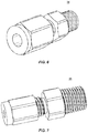
- FIG. 6 is a perspective view of a component of a delivery system in accordance with the principles of the present disclosure.
- FIG. 7 is a perspective view of a component of a delivery system in accordance with the principles of the present disclosure.
- FIG. 8 is a perspective view of a component of a delivery system in accordance with the principles of the present disclosure.
- FIG. 9 is a perspective view of a component of a delivery system in accordance with the principles of the present disclosure.
- FIG. 10 is a perspective view of a component of a delivery system in accordance with the principles of the present disclosure.
- FIG. 11 is a perspective view of a component of a delivery system in accordance with the principles of the present disclosure.
- FIG. 12 is a perspective view of a component of a delivery system in accordance with the principles of the present disclosure.
- FIG. 13 is a perspective view of a component of a delivery system in accordance with the principles of the present disclosure.
- FIG. 14 is a perspective view of a component of a delivery system in accordance with the principles of the present disclosure.
- FIG. 15 is a perspective view of a component of a delivery system in accordance with the principles of the present disclosure.
- FIG. 16 is a perspective view of a component of a delivery system in accordance with the principles of the present disclosure.
- FIG. 17 is a perspective view of a component of a delivery system in accordance with the principles of the present disclosure.
- FIG. 18 is a perspective view of a component of a delivery system in accordance with the principles of the present disclosure.
- FIG. 19 is a perspective view of a component of a delivery system in accordance with the principles of the present disclosure.
- a delivery system and related methods are discussed in terms of medical devices for the treatment of skeletal injuries, disorders and repairs and more particularly, in terms of a mixing and dispensing gun and method for bone repair.
- the system and method may be employed in applications such as correction of cracks, fissures, voids, e.g., due to osteoporosis or other diseases or injuries.
- the system and method may be employed with the placement of support structures or devices attached to or embedded within bone.
- such structures may include pins, screws, replacement joints (e.g., of the hip, knee, shoulder), etc.
- the delivery system includes a device, such as, for example, a master cylinder including two chambers.
- the chambers are filled with a fluid material.
- the device includes chambers disposed in series so as to synchronize expulsion of the fluid to actuate a bone filler dispenser.
- the series configuration facilitates control of the mixture ratio.
- the device is configured to facilitate use with low pressure applications where space is readily available.
- the device is configured to provide for remote delivery (i.e. out of floro) and high pressure delivery.
- the device provides a minimal footprint and a less cumbersome configuration.
- the device maximizes the use of hydraulic pressures but utilizing a dual circuit hydraulic cylinder delivery system.
- the device utilizes hydraulic pressure to simultaneously apply pressure on two plungers that are mechanically connected in series.
- force is applied to a distal plunger.
- the device allows for a single hydraulic force to act on two plungers, maximizing output force while minimizing input force. In some embodiments, the device allows for a single hydraulic signal to dispense cement at a 1:1 ratio (or any other ratio) which is critical to ensure proper mixing of materials.
- the master cylinder includes a hydraulic port.
- the mixer includes a first and a second chamber.
- the device is configured for connection with a hydraulic source and/or inflation syringe.
- the first chamber includes a plunger and the second chamber includes a plunger.
- the first chamber includes a smaller volume due to disposal of a plunger shaft therein.
- the second chamber includes a smaller diameter to account for volume differential.
- the first chamber includes a first material.
- the second chamber includes a second material.
- the first chamber is configured with a port to expel the first material to a static mixer.
- the second chamber includes a port to expel the second material to the static mixer.
- the device includes a rod disposed with the first chamber configured with a diameter equal to the CDS cartridge.
- the first chamber includes a seal configured to resist and/or prevent material from mixing within the chamber.
- the second chamber includes an air vent.
- the ports are configured for connection with tubing such as, for example, 3 ⁇ 4 inch tubing.
- the ports include universal end caps for connection with the tubing.
- the plunger in the first chamber includes a slot for engagement with an instrument such as, for example, a driver.
- the device expels the materials through the ports to a static mixer.
- the static mixer includes a mixing blade.
- the ports a disposed perpendicular to an axis of the mixer.
- the ports are disposed transverse to an axis of the mixer.
- the static mixer is connected with a cannula for disposal with a surgical site.
- the device is configured for connection with a dual chamber plunger.
- the dual chamber plunger is connected with the static mixer.
- one or all of the components of the surgical system may be disposable, peel-pack, pre-packed sterile devices.
- One or all of the components of the surgical system may be reusable.
- the surgical system may be configured as a kit with multiple sized and configured components.
- the present disclosure may be employed to treat or repair bone injuries or disorders such as, for example, osteoporosis, joint replacement, fracture repairs, bone breaks, etc.
- the present disclosure may be employed with other osteal and bone related applications, including those associated with diagnostics and therapeutics, such as the delivery of a therapeutic agents to a site for treatment or the delivery of radio opaque markers for tracking fluid once it is released into a patient.
- the disclosed surgical system and methods may be alternatively employed in a surgical treatment with a patient in a prone or supine position, and/or employ various surgical approaches, including anterior, posterior, posterior mid-line, direct lateral, postero-lateral, antero-lateral approaches, etc. in any body region.
- the system and methods of the present disclosure may also be used on animals, bone models and other non-living substrates, such as, for example, in training, testing and demonstration.
- Ranges may be expressed herein as from “about” or “approximately” one particular value and/or to “about” or “approximately” another particular value. When such a range is expressed, another embodiment includes from the one particular value and/or to the other particular value. Similarly, when values are expressed as approximations, by use of the antecedent “about,” it will be understood that the particular value forms another embodiment. It is also understood that all spatial references, such as, for example, horizontal, vertical, top, upper, lower, bottom, left and right, are for illustrative purposes only and can be varied within the scope of the disclosure. For example, the references “upper” and “lower” are relative and used only in the context to the other, and are not necessarily “superior” and “inferior”.
- treating or “treatment” of a disease or condition refers to performing a procedure that may include administering one or more drugs to a patient (human, normal or otherwise or other mammal), in an effort to alleviate signs or symptoms of the disease or condition. Alleviation can occur prior to signs or symptoms of the disease or condition appearing, as well as after their appearance.
- treating or treatment includes preventing or prevention of disease or undesirable condition (e.g., preventing the disease from occurring in a patient, who may be predisposed to the disease but has not yet been diagnosed as having it).
- treating or treatment does not require complete alleviation of signs or symptoms, does not require a cure, and specifically includes procedures that have only a marginal effect on the patient.
- Treatment can include inhibiting the disease, e.g., arresting its development, or relieving the disease, e.g., causing regression of the disease.
- treatment can include reducing acute or chronic inflammation; alleviating pain and mitigating and inducing re-growth of new ligament, bone and other tissues; as an adjunct in surgery; and/or any repair procedure.
- tissue includes soft tissue, ligaments, tendons, cartilage and/or bone unless specifically referred to otherwise.
- FIGS. 1-19 there are illustrated components of a surgical system, such as, for example, a delivery system 10 .
- the components of spinal implant system 10 can be fabricated from biologically acceptable materials suitable for medical applications, including metals, synthetic polymers, ceramics and bone material and/or their composites.
- the components of spinal implant system 10 individually or collectively, can be fabricated from materials such as stainless steel alloys, commercially pure titanium, titanium alloys, Grade 5 titanium, super-elastic titanium alloys, cobalt-chrome alloys, stainless steel alloys, superelastic metallic alloys (e.g., Nitinol, super elasto-plastic metals, such as GUM METAL® manufactured by Toyota Material Incorporated of Japan), ceramics and composites thereof such as calcium phosphate (e.g., SKELITETM manufactured by Biologix Inc.), thermoplastics such as polyaryletherketone (PAEK) including polyetheretherketone (PEEK), polyetherketoneketone (PEKK) and polyetherketone (PEK), carbon-PEEK composites, PEEK-BaSO4 polymeric rubbers, polyethylene ter
- the components of system 10 may also be fabricated from a heterogeneous material such as a combination of two or more of the above-described materials.
- the components of system 10 may be monolithically formed, integrally connected or include fastening elements and/or instruments, as described herein.
- System 10 is employed, for example, with an open, mini-open or minimally invasive surgical technique to fill voids, provide patches, attach prosthetic devices, etc., or any other bone related repairs.
- System 10 includes a device, such as, for example, a master cylinder 12 configured to simultaneously actuate translation of plungers in a bone filling dispenser 100 , as described herein.
- the plungers are actuated to translate at an equal rate.
- utilization of cylinder 12 facilitates the utilization of a hydraulic force applied to actuate the plungers, as described herein.
- Cylinder 12 includes a body 14 .
- Body 14 extends between a proximal end 18 and a distal end 20 defining a longitudinal axis X 1 .
- Body 14 includes a barrel that encloses a chamber 22 and a chamber 24 .
- body 14 may have cross section configurations, such as, for example, oval, cylindrical, triangular, square, polygonal, irregular, uniform, non-uniform, offset, staggered, undulating, arcuate, variable and/or tapered.
- a wall of barrel 14 can be flexible, elastic, semi-rigid or rigid.
- Chambers 22 , 24 are disposed in a series configuration, as described herein.
- Chamber 22 includes a port 26 configured for connection with an actuator, such as, for example, a hydraulic pressure source.
- Port 26 defines an opening and is configured for connection with tubing configured for attachment with the pressure source.
- port 26 includes a taper, nozzle, valve and/or luer lock connection for connecting with the tubing.
- port 26 includes a pressure fit, friction fit or threaded connection for connecting with the tubing.
- port 26 is integrally connected or monolithically formed with the tubing.
- the tubing includes 3 ⁇ 4 inch tubing.
- Chamber 22 includes a pneumatic material, such as, for example a fluid.
- the fluid may be, such as, for example, water, oil or saline.
- Chamber 22 includes a plunger 30 configured to actuate movement of the fluid within chamber 22 .
- the pressure source applies a force to plunger 30 to actuate translation of plunger 30 within chamber 22 .
- Plunger 30 includes a first part 30 a and a second part 30 b that is movable relative to first part 30 a .
- First part 30 a includes a channel 35 that is in communication with a lumen 37 of port 26 .
- Second part 30 b of plunger 30 includes a shaft 32 configured for engagement with a plunger 40 to actuate translation of plunger 40 within chamber 24 .
- Plunger 30 is configured to actuate movement of the fluid within chamber 22 .
- First part 30 a of plunger 30 includes a recess 31 a having a plunger seal 33 a disposed therein that slidably engages the wall of chamber 22 .
- second part 30 b of plunger 30 includes a recess 31 b having a plunger seal 33 b disposed therein that slidably engages the wall of chamber such that second part 30 b is movably disposed with body 14 .
- Plunger seal 33 a and/or plunger seal 33 b is/are configured to resist and/or prevent the fluid within chamber 22 from exiting chamber 22 .
- Plunger seal 33 b is configured to translate within chamber 22 and contact the fluid within chamber 22 .
- Second part 30 b of plunger 30 translates along axis X 1 relative to body 14 between an initial orientation and a fully or entirely expelled orientation. In the initial orientation, second part 30 b of plunger 30 is disposed adjacent the fluid within chamber 22 .
- Second part 30 b of plunger 30 translates such that plunger seal 33 b applies a force to the fluid within chamber 22 .
- the force applied by plunger seal 33 b causes the fluid to be moved through an opening 50 .
- opening 50 is disposed perpendicular relative to axis X 1 . Compression of the first material causes the fluid within chamber 22 to flow from chamber 22 through opening 50 .
- chamber 22 includes an O-ring retainer 54 .
- O-ring retainer 54 is configured to facilitate movement of the fluid within chamber 22 through opening 50 .
- Chamber 24 includes the second material.
- the second material includes a pneumatic material, such as, for example a fluid.
- the fluid may be, such as, for example, water, oil or saline.
- Plunger 40 is actuated by second part 30 b of plunger 30 such that plungers 30 , 40 expel the fluid from chambers 22 , 24 simultaneously from cylinder 12 .
- Disposal of chambers 22 , 24 in the series configuration allows the force applied to second part 30 b of plunger 30 to translate plunger 40 . In some embodiments, this configuration utilizes a reduced and/or lower hydraulic force to expel the fluid.
- the force applied to plungers, 30 , 40 is configured to simultaneously expel the fluid from chambers 22 , 24 .
- Plunger 40 is configured to actuate movement of the fluid within chamber 24 .
- Plunger 40 includes a recess 41 having a plunger seal 43 disposed therein that slidably engages the wall of chamber 24 such that plunger 40 is movably disposed with body 14 .
- Plunger seal 43 is configured to resist and/or prevent the fluid within chamber 24 from exiting chamber 24 .
- Plunger seal 43 is configured to translate within chamber 24 and contact the fluid within chamber 24 .
- Plunger 40 translates relative to body 14 between an initial orientation and a fully or entirely expelled orientation. In the initial orientation, plunger 40 is disposed adjacent the fluid within chamber 24 . Plunger 40 translates such that plunger seal 43 applies a force to the second material. The force applied by plunger seal 43 causes the second material to be moved through an opening 60 .
- opening 60 is disposed coaxial relative to axis X 1 .
- opening 60 is disposed perpendicular to axis X 1 . Compression of the fluid within chamber 24 causes the second material to flow from chamber 24 through opening 60 . Movement of the fluid from chamber 24 causes a plunger in bone filling dispenser 100 to be actuated, as described herein.
- plunger 40 includes a slot configured for engagement with an instrument, such as, for example, a driver.
- chamber 24 includes an air vent configured to facilitate translation of plunger 40 upon actuation by plunger 30 .
- plunger seals 33 a , 33 b , 43 include O-rings, as shown in FIGS. 10 and 18 .
- chamber 22 includes a smaller volumetric capacity than chamber 24 due to the plunger shaft extending therethrough.
- chamber 24 includes a smaller diameter than chamber 22 to account for the volumetric difference.
- system 10 includes a pressure relief valve.
- system 10 is provided sterilized.
- system 10 is provided as a sterilized kit including bone filler dispenser 100 .
- opening 50 includes a port 52 having a taper, nozzle, valve and/or luer lock connection for connecting with the tubing. In some embodiments, opening 50 includes a pressure fit, friction fit or threaded connection for connecting with the tubing. In some embodiments, opening 50 is integrally connected or monolithically formed with the tubing. In some embodiments, the tubing includes 3 ⁇ 4 inch tubing. In some embodiments, opening 60 includes a port 62 having a taper, nozzle, valve and/or luer lock connection for connecting with the tubing. In some embodiments, opening 60 includes a pressure fit, friction fit or threaded connection for connecting with the tubing. In some embodiments, opening 60 is integrally connected or monolithically formed with the tubing. In some embodiments, the tubing includes 3 ⁇ 4 inch tubing. In some embodiments, the tubing has a length sufficient such to position the syringe out of a field of radiation.
- the tubing attached with opening 50 directs the fluid in chamber 22 to drive a plunger 102 within a barrel 104 of bone filler dispenser 100 , as shown in FIG. 5 .
- opening 60 directs the fluid in chamber 24 to drive a plunger 106 in a barrel 108 of bone filler dispenser 100 , as shown in FIG. 5 .
- Bone filler dispenser 100 includes a dual barrel chamber dispenser oriented in a parallel configuration. Connection of bone filler dispenser 100 with cylinder 12 is configured to facilitate movement and/or translation of viscous material disposed within barrels 104 , 108 .
- the fluid expelled form cylinder 12 drives plungers 102 , 106 disposed at an equal rate, such as, for example, a 1:1 ratio to simultaneous dispense the bone filling material in a static mixer.
- chambers 22 , 24 can be altered, such as, for example, by diameter and/or volumetric capacity to alter the rate of translation of the plungers, such as, for example, a 2:1 ratio.
- barrels 104 , 108 include different materials configured to be mixed before administering to a surgical site.
- bone filler dispenser 100 includes a single plunger and the fluid from chambers 22 , 24 applies a force to a surface of the single plunger to double the pressure applied to expel the bone fill material.
- a static mixer 120 is attached to an end of bone filler dispenser 100 .
- static mixer 120 includes a mixing element, such as, for example, a helical blade 122 configured to mix the materials, such as, for example, a first material and a second material within barrels 104 , 108 , respectively. At the point of entry of the first material is expelled from barrel 104 and the second material is expelled from barrel 108 onto an end of blade 122 .
- Blade 122 is configured to receive the first material on one side of the helix and the second material on a second side of the helix. As the materials flow over blade 122 , the first and second materials mix along the length of blade 122 within the static mixer.
- system 10 is employed with a surgical procedure, such as, for a treatment of bone injuries, to provide bone repairs, to strengthen or rebuild bones, etc.
- a surgical procedure such as, for a treatment of bone injuries, to provide bone repairs, to strengthen or rebuild bones, etc.
- one or all of the components of system 10 can be delivered or implanted as a pre-assembled device or can be assembled in situ.
- System 10 may be completely or partially revised, removed or replaced.
- system 10 and accessories thereof, described above can be employed during a surgical procedure for mixing and dispensing bone cement.
- a medical practitioner obtains access to a surgical site including a bone in any appropriate manner, such as through incision and retraction of tissues.
- system 10 can be used in any existing surgical method or technique including open surgery, mini-open surgery, minimally invasive surgery and percutaneous surgical implantation, whereby the bone is accessed through a mini-incision, or sleeve that provides a protected passageway to the area. Once access to the surgical site is obtained, the particular surgical procedure can be performed for treating or repairing the bone.
- a cutting instrument (not shown) creates a surgical pathway for implantation of components of system 10 .
- a preparation instrument (not shown) can be employed to prepare tissue surfaces of the bone, as well as for aspiration and irrigation of a surgical region according to the requirements of a particular surgical application.
- a material such as, for example, pressurized air or a hydraulic fluid is injected into port such that the material moves through lumen 37 and into channel 35 .
- the material causes second part 30 b to translate relative to first part 30 a along axis X 1 in the direction shown by the arrows in FIG. 2 .
- Translation of second part 30 b relative to first part 30 a along axis X 1 causes the pneumatic material within chamber 22 to move through opening 50 and causes shaft 32 to translate plunger 40 relative to body 14 in the direction shown by the arrows in FIG. 2 such that plunger 40 moves the second material in chamber 24 through opening 50 and port 52 .
- the pneumatic material moves out of opening 50 and into the tubing attached with opening 50 such that the pneumatic material drives plunger 102 to move a component of a bone cement within barrel 104 of bone filler dispenser 100 into static mixer 120 .
- the second material simultaneously moves out of opening 50 and port 52 and tubing attached with port 52 into static mixer 120 .
- the pneumatic material moves out of opening 50 and into the tubing attached with opening 50 at the same time the second material moves out of opening 50 and port 52 and tubing attached with port 52 to drives plungers 102 , 106 at an equal rate, such as, for example, a 1:1 ratio to simultaneously move the first and second components of the bone cement into static mixer 120 .
- Plungers 102 , 106 create a force that moves the first and second components of the bone cement through static mixer 120 such that the first and second components of the bone cement become mixed within static mixer 120 and the mixed first and second components of the bone cement exit static mixer through an opening in static mixer for delivery of the mixed bone cement to a target location or area, such as, for example, holes, fractures, voids and/or depressions in the bone such that the mixed bone cement fills all or at least a portion of the holes, fractures, voids and/or depressions to maintain or improve the bone's structural integrity.
- Components of system 10 e.g., a needle attached to bone filler dispenser 100 is delivered to the surgical site along the surgical pathway(s) and into or onto bone tissue.
- system 10 may also deliver an agent, which may be mixed in the bone cement or delivered separately from the bone cement.
- the bone cement may be a bone filler material that includes, for example, bone material including autograft, allograft, xenograft, MASTERGRAFT®, collagen or transgenic cortical and/or corticocancellous bone, and tissue growth or differentiation factors, partially resorbable materials, such as, for example, composites of metals and calcium-based ceramics, composites of PEEK and calcium based ceramics, composites of PEEK with resorbable polymers, totally resorbable materials, such as, for example, calcium based ceramics such as calcium phosphate, TCP, HA-TCP, calcium sulfate, or other resorbable polymers such as polylactide, polyglycolide, polytyrosine carbonate, polycaprolactone and their combinations.
- the agent may include therapeutic polynucleotides or polypeptides.
- the agent may include biocompatible materials, such as, for example, biocompatible metals and/or rigid polymers, such as, titanium elements, metal powders of titanium or titanium compositions, sterile bone materials, such as allograft or xenograft materials, synthetic bone materials such as coral and calcium compositions, such as HA, calcium phosphate and calcium sulfite, biologically active agents, for example, gradual release compositions such as by blending in a bioresorbable polymer that releases the biologically active agent or agents in an appropriate time dependent fashion as the polymer degrades within the patient.
- Suitable biologically active agents include, for example, BMP, Growth and Differentiation Factors proteins (GDF) and cytokines.
- the components of correction system 10 can be made of radiolucent materials such as polymers. Radiomarkers may be included for identification under x-ray, fluoroscopy, CT or other imaging techniques.
- the agent may include one or a plurality of therapeutic agents and/or pharmacological agents for release, including sustained release, to treat, for example, pain, inflammation and degeneration.
- microsurgical and image guided technologies may be employed to access, view and repair bone deterioration or damage, with the aid of the system 10 .
- the surgical instruments and assemblies are removed and the incision is closed.
Landscapes
- Health & Medical Sciences (AREA)
- Surgery (AREA)
- Orthopedic Medicine & Surgery (AREA)
- Life Sciences & Earth Sciences (AREA)
- Engineering & Computer Science (AREA)
- Chemical & Material Sciences (AREA)
- Chemical Kinetics & Catalysis (AREA)
- Medical Informatics (AREA)
- Biomedical Technology (AREA)
- Heart & Thoracic Surgery (AREA)
- Nuclear Medicine, Radiotherapy & Molecular Imaging (AREA)
- Molecular Biology (AREA)
- Animal Behavior & Ethology (AREA)
- General Health & Medical Sciences (AREA)
- Public Health (AREA)
- Veterinary Medicine (AREA)
- Mechanical Engineering (AREA)
- Dispersion Chemistry (AREA)
- Physics & Mathematics (AREA)
- Fluid Mechanics (AREA)
- Civil Engineering (AREA)
- Structural Engineering (AREA)
- Surgical Instruments (AREA)
- Prostheses (AREA)
- Materials For Medical Uses (AREA)
Abstract
Description
Claims (20)
Priority Applications (1)
| Application Number | Priority Date | Filing Date | Title |
|---|---|---|---|
| US16/437,345 US11045240B2 (en) | 2016-06-03 | 2019-06-11 | Dispensing system and method |
Applications Claiming Priority (3)
| Application Number | Priority Date | Filing Date | Title |
|---|---|---|---|
| US201662345404P | 2016-06-03 | 2016-06-03 | |
| US15/612,063 US10357300B2 (en) | 2016-06-03 | 2017-06-02 | Dispensing system and method |
| US16/437,345 US11045240B2 (en) | 2016-06-03 | 2019-06-11 | Dispensing system and method |
Related Parent Applications (1)
| Application Number | Title | Priority Date | Filing Date |
|---|---|---|---|
| US15/612,063 Continuation US10357300B2 (en) | 2016-06-03 | 2017-06-02 | Dispensing system and method |
Publications (2)
| Publication Number | Publication Date |
|---|---|
| US20190321088A1 US20190321088A1 (en) | 2019-10-24 |
| US11045240B2 true US11045240B2 (en) | 2021-06-29 |
Family
ID=59702758
Family Applications (2)
| Application Number | Title | Priority Date | Filing Date |
|---|---|---|---|
| US15/612,063 Active 2038-01-04 US10357300B2 (en) | 2016-06-03 | 2017-06-02 | Dispensing system and method |
| US16/437,345 Active 2037-12-08 US11045240B2 (en) | 2016-06-03 | 2019-06-11 | Dispensing system and method |
Family Applications Before (1)
| Application Number | Title | Priority Date | Filing Date |
|---|---|---|---|
| US15/612,063 Active 2038-01-04 US10357300B2 (en) | 2016-06-03 | 2017-06-02 | Dispensing system and method |
Country Status (6)
| Country | Link |
|---|---|
| US (2) | US10357300B2 (en) |
| EP (1) | EP3463130B1 (en) |
| KR (1) | KR102508839B1 (en) |
| CN (1) | CN109475374B (en) |
| CA (1) | CA3034189A1 (en) |
| WO (1) | WO2017208073A2 (en) |
Families Citing this family (2)
| Publication number | Priority date | Publication date | Assignee | Title |
|---|---|---|---|---|
| CN109640851B (en) * | 2016-06-03 | 2021-09-03 | 美敦力控股有限责任公司 | Dispensing system and method |
| CN112755826B (en) * | 2021-01-05 | 2022-10-04 | 华东理工大学 | Device and method for enhancing liquid-liquid emulsification |
Citations (11)
| Publication number | Priority date | Publication date | Assignee | Title |
|---|---|---|---|---|
| US20010008968A1 (en) * | 2000-01-18 | 2001-07-19 | Sulzer Orthopedics Ltd. | Pistol for the pressing out of bone cement with an attachable cement syringe |
| US20020049449A1 (en) * | 1999-03-16 | 2002-04-25 | Mohit Bhatnagar | Apparatus and method for fixation of osteoporotic bone |
| US20070228076A1 (en) | 2006-03-29 | 2007-10-04 | Horner Terry A | Single dose dual fluid cartridge for use with hand-held applicators |
| US20080272149A1 (en) * | 2007-03-05 | 2008-11-06 | Virnelson R Craig | Dual component dispenser |
| US20090171361A1 (en) | 2007-12-27 | 2009-07-02 | Melsheimer Jeffry S | Apparatus and method for mixing and dispensing a bone cement mixture |
| EP2269541A1 (en) | 2008-03-24 | 2011-01-05 | Terumo Kabushiki Kaisha | Bone cement injecting tool |
| US20110106054A1 (en) | 2009-10-29 | 2011-05-05 | Osborne Thomas A | Multi-lumen medical mixing device |
| EP2446973A2 (en) | 2010-11-01 | 2012-05-02 | Nordson Corporation | Multiple component dispensing cartridge, mixing nozzle and method for reducing contact between fluids |
| US20130013007A1 (en) * | 2011-07-05 | 2013-01-10 | Kyphon Sarl | Combination directional and non-directional bone tamp |
| US8439929B1 (en) * | 2009-11-09 | 2013-05-14 | Nordson Corporation | Method of preparing a gel matrix for grafting to a bone |
| US20180125558A1 (en) * | 2016-08-18 | 2018-05-10 | Spinal Elements, Inc. | Material delivery surgical device |
Family Cites Families (7)
| Publication number | Priority date | Publication date | Assignee | Title |
|---|---|---|---|---|
| US5370221A (en) * | 1993-01-29 | 1994-12-06 | Biomet, Inc. | Flexible package for bone cement components |
| EP1700639A1 (en) * | 2005-03-11 | 2006-09-13 | 3M Innovative Properties Company | Dispensing device |
| CN102482023A (en) * | 2009-01-12 | 2012-05-30 | 阿克蒂弗派克股份有限公司 | Packaged products, inserts and compartments for aseptic mixing of substances, along with methods for use therewith |
| ES2528222T3 (en) * | 2010-01-25 | 2015-02-05 | Tecres S.P.A. | Device for the preparation and administration of a mixture of two components |
| JP2013537504A (en) * | 2010-08-16 | 2013-10-03 | バイエル・マテリアルサイエンス・アクチェンゲゼルシャフト | Discharge module |
| WO2012094549A1 (en) * | 2011-01-06 | 2012-07-12 | Synthes Usa, Llc | Hydraulic injection system for bone cement |
| WO2015036992A2 (en) * | 2013-09-10 | 2015-03-19 | Augma Biomaterials Ltd. | Dual component applicator |
-
2017
- 2017-06-02 EP EP17757863.0A patent/EP3463130B1/en active Active
- 2017-06-02 CA CA3034189A patent/CA3034189A1/en active Pending
- 2017-06-02 CN CN201780032588.0A patent/CN109475374B/en active Active
- 2017-06-02 US US15/612,063 patent/US10357300B2/en active Active
- 2017-06-02 WO PCT/IB2017/000761 patent/WO2017208073A2/en not_active Ceased
- 2017-06-02 KR KR1020187037343A patent/KR102508839B1/en active Active
-
2019
- 2019-06-11 US US16/437,345 patent/US11045240B2/en active Active
Patent Citations (11)
| Publication number | Priority date | Publication date | Assignee | Title |
|---|---|---|---|---|
| US20020049449A1 (en) * | 1999-03-16 | 2002-04-25 | Mohit Bhatnagar | Apparatus and method for fixation of osteoporotic bone |
| US20010008968A1 (en) * | 2000-01-18 | 2001-07-19 | Sulzer Orthopedics Ltd. | Pistol for the pressing out of bone cement with an attachable cement syringe |
| US20070228076A1 (en) | 2006-03-29 | 2007-10-04 | Horner Terry A | Single dose dual fluid cartridge for use with hand-held applicators |
| US20080272149A1 (en) * | 2007-03-05 | 2008-11-06 | Virnelson R Craig | Dual component dispenser |
| US20090171361A1 (en) | 2007-12-27 | 2009-07-02 | Melsheimer Jeffry S | Apparatus and method for mixing and dispensing a bone cement mixture |
| EP2269541A1 (en) | 2008-03-24 | 2011-01-05 | Terumo Kabushiki Kaisha | Bone cement injecting tool |
| US20110106054A1 (en) | 2009-10-29 | 2011-05-05 | Osborne Thomas A | Multi-lumen medical mixing device |
| US8439929B1 (en) * | 2009-11-09 | 2013-05-14 | Nordson Corporation | Method of preparing a gel matrix for grafting to a bone |
| EP2446973A2 (en) | 2010-11-01 | 2012-05-02 | Nordson Corporation | Multiple component dispensing cartridge, mixing nozzle and method for reducing contact between fluids |
| US20130013007A1 (en) * | 2011-07-05 | 2013-01-10 | Kyphon Sarl | Combination directional and non-directional bone tamp |
| US20180125558A1 (en) * | 2016-08-18 | 2018-05-10 | Spinal Elements, Inc. | Material delivery surgical device |
Non-Patent Citations (3)
| Title |
|---|
| CNIPA—China Patent Office—Notice of the First Office Action, China Application No. 201780032588.0, dated Oct. 10, 2020. |
| International Search Report and Written Opinion of the International Searching Authority, European Patent Office, PCT/IB2017/000761, dated Dec. 13, 2018. |
| PCT/IB2017/000761—International Search Report, Written Opinion of the International Searching Authority EPO, dated Nov. 27, 2017. |
Also Published As
| Publication number | Publication date |
|---|---|
| US10357300B2 (en) | 2019-07-23 |
| KR102508839B1 (en) | 2023-03-13 |
| US20190321088A1 (en) | 2019-10-24 |
| EP3463130A2 (en) | 2019-04-10 |
| CN109475374B (en) | 2021-08-24 |
| CN109475374A (en) | 2019-03-15 |
| WO2017208073A2 (en) | 2017-12-07 |
| WO2017208073A3 (en) | 2018-01-11 |
| KR20190049625A (en) | 2019-05-09 |
| EP3463130B1 (en) | 2022-05-18 |
| CA3034189A1 (en) | 2017-12-07 |
| US20170348036A1 (en) | 2017-12-07 |
Similar Documents
| Publication | Publication Date | Title |
|---|---|---|
| US12172142B2 (en) | Bone cement mixing and delivery system with reduced fume exposure | |
| US9839889B2 (en) | Mixer gun system and method | |
| US11045240B2 (en) | Dispensing system and method | |
| US10188443B2 (en) | Bone cement mixing and delivery device | |
| US20150320470A1 (en) | Cement delivering device and method | |
| EP3154460B1 (en) | High pressure remote delivery system for cement and methods of use | |
| US10194965B2 (en) | Methods of filling bone using bone cement mixing and delivery devices | |
| US11576710B2 (en) | Dispensing system and method |
Legal Events
| Date | Code | Title | Description |
|---|---|---|---|
| AS | Assignment |
Owner name: MEDTRONIC HOLDING COMPANY SARL, SWITZERLAND Free format text: ASSIGNMENT OF ASSIGNORS INTEREST;ASSIGNOR:KYPHON SARL;REEL/FRAME:049434/0565 Effective date: 20180426 Owner name: KYPHON SARL, SWITZERLAND Free format text: ASSIGNMENT OF ASSIGNORS INTEREST;ASSIGNORS:SASAKI, NEIL;ARTHUR, AMY L.;BOLOSAN, SAMUEL V.;SIGNING DATES FROM 20170602 TO 20170603;REEL/FRAME:049433/0609 |
|
| FEPP | Fee payment procedure |
Free format text: ENTITY STATUS SET TO UNDISCOUNTED (ORIGINAL EVENT CODE: BIG.); ENTITY STATUS OF PATENT OWNER: LARGE ENTITY |
|
| STPP | Information on status: patent application and granting procedure in general |
Free format text: DOCKETED NEW CASE - READY FOR EXAMINATION |
|
| STPP | Information on status: patent application and granting procedure in general |
Free format text: NON FINAL ACTION MAILED |
|
| STPP | Information on status: patent application and granting procedure in general |
Free format text: RESPONSE TO NON-FINAL OFFICE ACTION ENTERED AND FORWARDED TO EXAMINER |
|
| STPP | Information on status: patent application and granting procedure in general |
Free format text: NOTICE OF ALLOWANCE MAILED -- APPLICATION RECEIVED IN OFFICE OF PUBLICATIONS |
|
| STPP | Information on status: patent application and granting procedure in general |
Free format text: PUBLICATIONS -- ISSUE FEE PAYMENT RECEIVED |
|
| STPP | Information on status: patent application and granting procedure in general |
Free format text: PUBLICATIONS -- ISSUE FEE PAYMENT VERIFIED |
|
| STCF | Information on status: patent grant |
Free format text: PATENTED CASE |
|
| MAFP | Maintenance fee payment |
Free format text: PAYMENT OF MAINTENANCE FEE, 4TH YEAR, LARGE ENTITY (ORIGINAL EVENT CODE: M1551); ENTITY STATUS OF PATENT OWNER: LARGE ENTITY Year of fee payment: 4 |
|
| AS | Assignment |
Owner name: MEDTRONIC EUROPE SARL, SWITZERLAND Free format text: MERGER;ASSIGNOR:MEDTRONIC HOLDING COMPANY SARL;REEL/FRAME:070809/0661 Effective date: 20241018 |