US11045156B2 - Method for periodontal disease measurement - Google Patents
Method for periodontal disease measurement Download PDFInfo
- Publication number
- US11045156B2 US11045156B2 US14/235,492 US201214235492A US11045156B2 US 11045156 B2 US11045156 B2 US 11045156B2 US 201214235492 A US201214235492 A US 201214235492A US 11045156 B2 US11045156 B2 US 11045156B2
- Authority
- US
- United States
- Prior art keywords
- tooth
- indicator
- ray
- computer
- contour
- Prior art date
- Legal status (The legal status is an assumption and is not a legal conclusion. Google has not performed a legal analysis and makes no representation as to the accuracy of the status listed.)
- Expired - Fee Related, expires
Links
Images


Classifications
-
- A—HUMAN NECESSITIES
- A61—MEDICAL OR VETERINARY SCIENCE; HYGIENE
- A61B—DIAGNOSIS; SURGERY; IDENTIFICATION
- A61B6/00—Apparatus or devices for radiation diagnosis; Apparatus or devices for radiation diagnosis combined with radiation therapy equipment
- A61B6/50—Apparatus or devices for radiation diagnosis; Apparatus or devices for radiation diagnosis combined with radiation therapy equipment specially adapted for specific body parts; specially adapted for specific clinical applications
- A61B6/51—Apparatus or devices for radiation diagnosis; Apparatus or devices for radiation diagnosis combined with radiation therapy equipment specially adapted for specific body parts; specially adapted for specific clinical applications for dentistry
-
- A61B6/14—
-
- A—HUMAN NECESSITIES
- A61—MEDICAL OR VETERINARY SCIENCE; HYGIENE
- A61B—DIAGNOSIS; SURGERY; IDENTIFICATION
- A61B6/00—Apparatus or devices for radiation diagnosis; Apparatus or devices for radiation diagnosis combined with radiation therapy equipment
- A61B6/02—Arrangements for diagnosis sequentially in different planes; Stereoscopic radiation diagnosis
- A61B6/03—Computed tomography [CT]
- A61B6/032—Transmission computed tomography [CT]
-
- A—HUMAN NECESSITIES
- A61—MEDICAL OR VETERINARY SCIENCE; HYGIENE
- A61C—DENTISTRY; APPARATUS OR METHODS FOR ORAL OR DENTAL HYGIENE
- A61C19/00—Dental auxiliary appliances
- A61C19/04—Measuring instruments specially adapted for dentistry
Definitions
- the present invention relates to a method for periodontal disease measurement. More specifically, the present invention relates to a method for measuring the progression of periodontal disease based on a two-dimensional image of an x-ray CT image of the teeth.
- Periodontal disease is a disease that affects a cementum portion around the teeth, in other words, the gingiva (gums), the alveolar bone, the periodontal ligament, and the root surface.
- gingiva gingiva
- periodontal disease indicates an inflammatory disease affecting around the teeth.
- the disease occupies 90% or more of patients. Therefore, a common periodontal disease is caused by microorganisms called periodontal bacteria such as Porphyromonas gingivalis.
- the present invention also mainly targets the common periodontal disease.
- the common periodontal disease is referred to as the “periodontal disease.” and a periodontal disease other than the common periodontal disease is referred to as the “special periodontal disease.”
- FIG. 3 is a cross-sectional view schematically illustrating a normal tooth.
- FIG. 4 is a cross-sectional view schematically illustrating a tooth affected by the periodontal disease.
- a normal tooth 30 has a root 31 supported by a periodontal ligament 32 a , an alveolar bone 35 , and a gingiva (or gums) 32 .
- a periodontal pocket (or simply “pocket” or “gingival sulcus”) 45 .
- the gingiva 32 and the periodontal ligament 32 a are affected by the periodontal disease.
- inflammation as in FIG. 4 is caused in the gingiva 32 and the periodontal ligament 32 a to cause bleeding and pus discharge 48 in the periodontal pocket 45 .
- the alveolar bone 35 starts to be resorbed and retracted.
- the depth of the pocket 45 from a gingival apex 46 to a pocket bottom 47 is approximately 0 to 1 mm in the healthy tooth 30 .
- the depth of a tooth 40 affected by the periodontal disease is increasingly deepened with the progress of the periodontal disease.
- the probing measurement is a method for measuring the state of the symptom while introducing a probe (a needle for examination) into the pocket 45 and measuring the depth of the pocket 45 , and is the simplest method. This method is superior in a respect of being applicable to symptoms at all stages. However, the measurement results vary depending on the skill level of an examiner. Moreover, especially in a severe case, there is a problem in causing pain to a patient since the probe stimulates the nerve. In other words, in the measurement of the depth of the pocket 45 , a probe (a needle for measurement, or specifically, a needle calibrated with markings called a pocket probe) is introduced until reaching the lower end of the pocket. For one tooth 40 , the measurement is performed at approximately six points and may involve bleeding.
- the measurement causes pain to a patient and takes time and effort. Moreover, there is a problem in that it may be insufficient as an objective indicator of the periodontal disease. In other words, even if the pockets 45 have the same depth, the volume of the tooth 40 below the pocket 45 varies depending on the tooth 40 or varies from person to person. In other words, the force supporting the tooth 40 cannot be determined only from the depth of the pocket 45 .
- the measurement using intraoral radiography or panoramic x-ray imaging is a method where the bone level and the external shape of the alveolar bone 35 are grasped from an x-ray of the (three-dimensional) tooth 40 and periodontal tissue to make a measurement. How much the tooth 40 is supported by the alveolar bone is measured based on the bone level and the external shape of the alveolar bone 35 .
- This method is superior to the probing method in that reading can be performed with higher accuracy.
- the method cannot be used at the initial stage where the pocket 45 has just been formed, and cannot be used frequently.
- the measurement using a bacteriological examination is a method where the causative bacteria of periodontal inflammation are examined to measure the activity/progressiveness of the periodontal disease.
- the activity can be therefore determined by identifying the species of bacteria.
- the identification of bacterial species involves the problem of time and cost and is not simple.
- Patent Literature 1 a remaining teeth prediction system is proposed (Patent Literature 1).
- the prediction system evaluates a reduction in root surface area from the total surface area of currently effective roots, and the result is then used to predict a reduction in the number of remaining teeth.
- a reduction in the total surface area of effective roots is represented by a curve or a straight line to predict the number of remaining teeth, which can be easily figured out.
- the method has an advantage that the result can be used as a material for long-term teeth prevention, treatment, and instruction.
- the root surface area is hardly obtained with high accuracy because of being calculated from a probing attachment level (the ratio of a portion where the gingiva is attached to a tooth). Sufficient satisfaction cannot be always obtained in that the resorption of the alveolar bone is not considered.
- Patent Literature 2 an electronic medical support apparatus compares a plaque score, periodontal pocket depth, and tooth mobility with their past data to calculate the progression rate of the periodontal disease. Based on the progression rate, information on the progression prediction of the periodontal disease is displayed.
- the technology has an advantage that can cause a patient to recognize the importance of periodontal disease treatment by motivating the patient. However, it is not necessarily fully satisfying in a respect that alveolar bone resorption is not considered.
- An object of the present invention is to provide a method for periodontal disease measurement that can obtain an indicator indicating the symptoms of periodontal disease objectively, simply and highly accurately without causing pain to a patient. More specifically, an issue of the present invention is to provide the following method for periodontal disease measurement.
- the measurement can collect an indicator indicating the progression of periodontal disease of a patient by x-ray CT without causing pain to the patient and causing a dentist to spend time and effort, achieve a highly accurate calculation for obtaining an objective indicator, and improve the accuracy of automatic detection measurement.
- the present invention provides the following method for periodontal disease measurements to achieve the aforementioned object.
- a first measurement is a method for periodontal disease measurement including: using a plurality of cross-sectional images provided by x-ray CT images of teeth and periodontal tissues to detect a contour of each tooth in each of the cross-sectional images, detect a dentition, and provide a dental formula; detecting the positions of the root apex, the alveolar crest, and the crown of each tooth from the detected tooth contour data; calculating at least one of a distance indicator, a volume indicator, a surface area indicator, a first moment indicator, a center-of-gravity indicator, and an alveolar bone indicator from the detected tooth contour data, and the position data of the root apex, the alveolar crest, and the crown of the tooth; and measuring the progression of periodontal disease based on at least one calculated indicator.
- a second measurement is a method for periodontal disease measurement according to the first measurement, wherein the distance indicator is a value calculated as a ratio DC/DF of a length DC of the root surrounded by the alveolar bone currently supporting the tooth to a tooth length DF calculated based on the data of the root apex, the alveolar crest, and the crown.
- a third measurement is a method for periodontal disease measurement according to first measurement, wherein the volume indicator is a value calculated as a ratio VC/VF of volume VC of the root surrounded by the alveolar bone currently supporting the tooth to tooth volume VF calculated based on the data of the root apex, the alveolar crest, and the crown.
- a fourth measurement is a method for periodontal disease measurement according to the first measurement, wherein the surface area indicator is a value calculated as a ratio SC/SF of a surface area SC of the root surrounded by the alveolar bone currently supporting the tooth to a tooth surface area SF calculated based on the data of the root apex, the alveolar crest, and the crown.
- a fifth measurement is a method for periodontal disease measurement according to the first measurement, wherein the first moment indicator is a value calculated as a ratio MC/MF of a first moment MC of the root surrounded by the alveolar bone currently supporting the tooth to a first moment MF of the tooth calculated based on the data of the root apex, the alveolar crest, and the crown.
- a sixth measurement is a method for periodontal disease measurement according to the first measurement, wherein the center-of-gravity indicator is a value calculated as a ratio GC/GF of the center of gravity GC of the root surrounded by the alveolar bone currently supporting the tooth to the tooth's center of gravity GF calculated based on the data of the root apex, the alveolar crest, and the crown.
- the center-of-gravity indicator is a value calculated as a ratio GC/GF of the center of gravity GC of the root surrounded by the alveolar bone currently supporting the tooth to the tooth's center of gravity GF calculated based on the data of the root apex, the alveolar crest, and the crown.
- a seventh measurement is a method for periodontal disease measurement according to the first measurement, wherein the contour of the tooth is determined by calculating the roundness of the tooth from the detected tooth contour data and comparing the roundness with a standard feature value.
- An eighth measurement is a method for periodontal disease measurement according to the first measurement, wherein the centers of gravity of the teeth are obtained from the detected tooth contour data, a curve passing around the obtained centers of gravity of the respective teeth is obtained, and the contour of the tooth is determined by the curve.
- a ninth measurement is a method for periodontal disease measurement according to the first measurement, wherein the contour is determined by a CT image adjacent to a cross section photographed by the x-ray CT apparatus.
- a tenth measurement is a method for periodontal disease measurement according to the first measurement, wherein the root apex, the alveolar crest, and the crown are determined by standard feature values and corresponding portions of another tooth in the vicinity.
- An eleventh measurement is a method for periodontal disease measurement according to the first measurement, wherein the alveolar crest is determined by the alveolar bone around the contour.
- a twelfth measurement is a method for periodontal disease measurement according to the first measurement, wherein the dentition is determined by referring to a reference dentition pattern.
- a thirteenth measurement is a method for periodontal disease measurement according to the first measurement, further comprising, upon detecting a dentition and providing a dental formula, projecting the dentition on a curved surface along the dentition to create and display a panoramic image, and superimposing and displaying the dental formula thereon.
- a fourteenth measurement is a method for periodontal disease measurement according to the thirteenth measurement, wherein the curved surface is a curved surface parallel to a tooth axis.
- a fifteenth measurement is a method for periodontal disease measurement according to the first measurement, wherein the dental formula is displayed using a plurality of different colors.
- a sixteenth measurement is a method for periodontal disease measurement according to the first measurement, further comprising, upon determining the degree of a disease of teeth and periodontal tissues based on the indicator, comparing the indicator with an indicator previously obtained.
- the present invention can obtain an effect where an indicator indicating the state of periodontal disease objectively can be obtained simply and highly accurately without causing pain to a patient. More specifically, the present invention can obtain the following effects. In other words, it becomes possible to collect an indicator indicating the progression of periodontal disease of a patient by x-ray CT without causing pain to the patient and causing a dentist to spend time and effort, achieve a highly accurate calculation for obtaining an objective indicator, and improve the accuracy of automatic detection measurement.
- FIG. 1 is a flowchart illustrating a method for periodontal disease measurement according to an embodiment of the present invention.
- FIG. 2 schematically illustrates an apparatus that is used for the method for periodontal disease measurement according to the embodiment of the present invention and connected to an x-ray imaging apparatus, a computer, and an image display device.
- FIG. 3 schematically illustrates a cross section of a normal tooth.
- FIG. 4 schematically illustrates a cross section of a tooth affected by periodontal disease.
- FIG. 5( a ) is an explanatory view schematically illustrating the alveolar bone
- FIG. 5( b ) is an x-ray CT image illustrating the alveolar bone.
- FIGS. 6( a ) to 6( h ) are a plurality of x-ray CT images of the teeth of a patient, and are images illustrating progressively lower levels from (a) toward (h).
- FIG. 7 illustrates a midline and a dental formula.
- FIG. 8 illustrates a reference dentition pattern
- FIG. 9 illustrates an example of a contour detection result.
- FIG. 10 illustrates a curve passing around the center of gravity of each tooth.
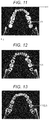
- FIG. 11 illustrates a tooth contour of x-ray CT image number 192 .
- FIG. 12 illustrates the tooth contour of x-ray CT image number 180 .
- FIG. 14 illustrates the tooth contour of x-ray CT image number 168 .
- FIG. 15 illustrates the tooth contour of x-ray CT image number 155 .
- FIG. 16 illustrates a panoramic image projected on a curved surface passing around the center of gravity of each tooth.
- FIG. 1 is a flowchart illustrating a method for periodontal disease measurement according to the embodiment of the present invention.
- FIG. 2 is a diagram illustrating an apparatus that is used for the method for periodontal disease measurement according to the embodiment of the present invention and connected to a dental x-ray imaging apparatus, a computer, and an image display device.
- the teeth of an animal such as a human or dog are photographed by dental radiography to obtain a plurality of x-ray CT images.
- the plurality of obtained CT images is read in one by one to be displayed (Step S- 1 ).
- a midline is detected on the displayed CT image (Step S- 2 ).
- the contour of each tooth is detected on each CT image (Step S- 3 ).
- the contour of each tooth is detected between the CT images (Step S- 4 ).
- a dental formula is provided (Step S- 5 ).
- the root apex, the alveolar crest, and the crown are detected (Step S- 6 ).
- the detection result is displayed (Step S- 7 ).
- the method for periodontal disease measurement for measuring the progression of periodontal disease uses, for example, a system connected to an x-ray CT imaging apparatus 20 , a computer (PC) 21 , and an image display device (monitor) 22 .
- the x-ray CT imaging apparatus 20 photographs the teeth of a patient.
- the computer (PC) 21 automatically detects the root apex, the alveolar crest, and the crown from a two-dimensional image obtained by capturing the photographed x-ray CT image and displays the result on the image display device (monitor) 22 . If there is an error in detection, a correction instruction is given by, for example, a light pen 24 on the displayed image. An instruction may be given by a cursor instead of the light pen 24 .
- Step S 1 is a CT image processing step.
- the teeth of a human or animal are photographed by x-ray CT first. Consequently, several tens to several hundreds of successive CT images of thin cross sections are obtained. The obtained CT images are captured one by one and displayed.
- the above-mentioned method is used to obtain successive cross-sectional x-ray CT images by photographing the teeth of a human or animal by x-rays.
- an alveolar bone 51 is photographed but a gingiva 32 is hardly photographed in the x-ray CT images.
- a tooth 30 is supported by an alveolar bone 35 and the gingiva (gums) 32 .
- a cervix 33 and a gingival apex 46 are aligned in the healthy tooth 30 .
- the gingiva 32 is in close contact with the cervix 33 and supports the tooth 30 .
- the gingiva pulls away from the tooth to form a pocket 45 .
- bleeding and pus discharge 48 are caused in a severe case.
- the portion from the gingival apex 46 to the bottom of the pocket 45 cannot support the tooth 30 . If periodontal disease progresses, the alveolar bone 35 is also resorbed and retracted. The force of the alveolar bone 35 and the gingiva 32 to support the tooth 40 is reduced.
- FIGS. 6( a ) to 6( h ) illustrate the plurality of obtained x-ray CT images of the teeth of the patient. The images represent progressively lower levels from (a) toward (h).
- FIGS. 6( a ) to 6( h ) illustrate examples of every 10 images from the 200th image to the 130th image among approximately 500 x-ray CT images photographed at intervals of 0.3 mm.
- the x-ray CT image is a tomographic image obtained by acquiring data using a computer and reconstructing an image. Especially, in the case of dental x-ray CT, it is possible to observe a fine cross-sectional image with little distortion by short-time x-ray irradiation. It is possible to accurately diagnose/examine hard tissues of the head and neck such as jaws, teeth, and oral region, and their surrounding tissues with a three-dimensional image. Hence, it exerts the effect on implant treatment and diagnosis/measurement/treatment of temporomandibular joint disease, a periapical lesion, and the like. Furthermore, since x-rays are irradiated for a short time, exposure is also reduced compared with conventional CT. Hence, safer and more secure treatment can be offered.
- the resolution of the apparatus is approximately 0.1 mm to 0.5 mm.
- the detection process will be described.
- the order of the steps may be changed. Moreover, not all the steps may be included.
- the order of detection is only an example.
- Step S 2 is the step of detecting a midline.
- the image (d) where all the teeth have been photographed is selected to detect a midline 71 . Detection is automatically performed.
- Software on the computer 21 detects the center of the jawbone, the margin of a tooth, and the like, compares them with a reference dentition pattern 81 of FIG. 8 , and the like, and determines and displays the midline 71 .
- An operator checks the detection result, and if it is wrong, corrects the result on the image.
- a dental formula (the numbers of teeth) is noted by L 1 , L 2 , . . . , R 1 , R 2 , . . . in FIG. 7 . At this stage, the dental formula is not automatically provided yet.
- Step S 3 is the step of detecting tooth contours in one image.
- the software detects the contour of each tooth as illustrated in FIG. 9 .
- a contour is detected by contour tracking or the like.
- the circumference L, inner surface area A, roundness (L 2 /A) of the contour are calculated and compared with the respective standard feature values to determine it as a tooth and conclude its shape.
- the standard feature values include the position of each tooth, a fact that tooth size is 15 mm or less, a fact that canine tooth is slightly larger, and a fact that teeth after tooth number six have a plurality of roots.
- a method for creating and checking a connected curve will be described. As illustrated in FIG. 10 , a spline curve 101 passing around the centers of gravity of the detected teeth is created. This is a method to correct the data if the teeth are not aligned on such a line. If each individual tooth deviates greatly from the curve 101 , an average value of adjacent teeth is used to correct the data and display an alert.
- Step S 4 tooth contour detection between images whose cross sections are adjacent is performed.
- FIGS. 11 to 15 respectively illustrate a tooth contour 111 of x-ray CT image numbers 192 , 180 , 170 , 168 , and 155 .
- the contour 111 in FIGS. 11 to 15 indicates the contour of the tooth L 7 . Assume that there are small, gradual differences in the center of gravity, the circumference, the contour shape, and the like between adjacent CT images. If the changes are not smooth, they are corrected by the software and an alert is displayed. In other words, “determination by adjacent CT images” is achieved.
- the position where the contour cannot be detected is the root apex or the crown.
- the position of the contour (root) shifts from its initial position because it moves diagonally as the x-ray CT images change.
- the x-axis and y-axis are taken as illustrated in FIG. 11
- the z-axis is taken in a manner of being vertical with respect to the paper and facing the other way.
- the tooth axis may not be parallel to the z-axis.
- the inclination of the tooth axis with respect to the z-axis is calculated to be used later for a correction of a distance calculation, a correction of display, and the like.
- Step S 5 is the step of providing a dental formula.
- a final dental formula determined from the result is provided as L 1 , L 2 , L 3 , . . . , R 1 , R 2 , R 3 , . . . as illustrated in FIG. 7 , and is displayed. If there is an error, the error is corrected (by the operator).
- Step S 6 is the step of detecting the root apex, the alveolar crest, and the crown.
- Data on the root apex, the alveolar crest, and the crown is detected. Detection is automatically performed. The detected data on the root apex, the alveolar crest, and the crown is displayed. The operator checks the detection result, and if it is wrong, a correction is made.
- the root apex is set to a position where the contour is no longer detected on the lower side.
- the crown is set to a position where the contour is no longer detected on the upper side.
- the alveolar crest is determined by the alveolar bone around the contour. For example, the alveolar crest is set to the topmost position within a designated width around the contour of the tooth in which the alveolar bone exists. Looking at 111 (L 7 ) of FIG.
- CT image number 170 the alveolar bone is visible around the contour of the tooth. If the alveolar bone is not visible in the images with higher numbers than 170 , the alveolar crest of L 7 is 170 . Similarly, the alveolar crest of each tooth is detected.
- the alveolar crest may not be uniform around the tooth. Looking around the tooth 111 (L 7 ) of number 170 in FIG. 13 , the alveolar bone is visible on the upper, right, and lower sides, but is not visible in any other directions. The alveolar bone comes into sight also on the left side in number 168 in FIG. 14 . In this manner, the heights of the alveolar crest are detected in a plurality of directions. Consequently, it is also possible to cover the measurement by generally measuring six points around a tooth by probing.
- This method assumes that the root apex, the alveolar crest, and the crown of the adjacent tooth are in substantially similar positions, and corrects data. If the positions of the root apex, the alveolar crest, and the crown are greatly different from those of the adjacent tooth, these positions are set to average values between the adjacent teeth, and an alert is displayed to prompt the operator to make corrections. In other words, “the determination of the root apex, the alveolar crest, and the crown by corresponding portions of another tooth in the vicinity” is achieved.
- Step S 7 is a result display step.
- FIG. 16 is an image where the original image portion with the thickness of a fixed width from a curved surface 133 to a curved surface 132 parallel to a curved surface 131 parallel to the tooth axis (z-axis) passing around the positions of the detected teeth are projected on the curved surface 131 as illustrated in FIG. 17 .
- a correct length is projected by inclining the curved surface in agreement with the inclination of the tooth axis.
- the tooth axis of an anterior tooth is not parallel to the z-axis in many cases.
- the correct length is projected by inclining the curved surface in agreement with the inclination of the tooth axis.
- the cross sections of the detected teeth are superimposed on FIG. 16 , and further, the dental formula is also superimposed and displayed as illustrated in FIG. 18 .
- the dental formula is displayed using a plurality of different colors. For example, R 1 and L 1 are illustrated in blue, R 2 and L 2 in cyan, R 3 and L 3 in blue green, R 4 and L 4 in green, R 5 and L 5 in yellow green, R 6 and L 6 in orange, R 7 and L 7 in red, and R 8 and L 8 in magenta. There is no R 8 in FIG. 18 .
- Step S 8 is the step of calculating an indicator of a distance, the volume of the root, the surface area of the root, the first moment of the root, or the center of gravity.
- At least one indicator of a distance indicator, a volume indicator, a surface area indicator, a first moment indicator, and a center-of-gravity indicator is calculated based on the detected data on the root apex, the alveolar crest, and the crown.
- the positions of the root apex, the alveolar crest, and the crown detected in Step S 6 are used to calculate an indicator of at least one of a distance, volume, a surface area, a first moment, or the center of gravity.
- each indicator will be described in turn.
- a distance indicator (root distance indicator) (KD) being an indicator of the state of a tooth can be calculated as follows. Prior to the calculation of the distance indicator (root distance indicator) (KD), an entire length (DF) of one tooth is calculated first as follows. In other words, a length from the root apex 34 to the crown 37 is set as the tooth length (DF).
- a length (DC) of the root surrounded by the alveolar bone is calculated as follows. In other words, the length from an alveolar crest 35 a to the root apex 34 is set as the length (DC) of the root surrounded by the alveolar bone.
- the distance indicator (root distance indicator) (KD) being the indicator of the state of a tooth is calculated as a ratio (DC/DF) of the length (DC) of the root surrounded by the alveolar bone currently supporting the tooth to the entire length (DF) of the tooth calculated from the above.
- a volume indicator (root volume indicator) (Kv) being an indicator of the state of a tooth can be calculated as follows.
- the volume (VF) of the entire tooth is calculated first as follows.
- the contour is automatically detected in the x-ray CT image to calculate its area. This is continued from the root apex to the crown. The sum of them is set as the volume (VF).
- the area is the number of pixels surrounded by the contour. The summation of the number of pixels of the inside surrounded by the contour is performed. This is converted to an actual unit.
- the volume (VF) of the tooth can be calculated by a mathematical equation (4).
- a symbol “SUR” in the mathematical equation (4) indicates the area in the contour of the tooth on a (x, y) coordinate plane with the z-coordinate of z.
- a symbol “HA” indicates the z-coordinate of the root apex 34 .
- a symbol “HC” indicates the z-coordinate of the crown. The same shall apply below.
- the numbers of pixels may be summed and converted to an actual unit.
- V F ⁇ HA HC ⁇ ⁇ d ⁇ ⁇ z ⁇ ⁇ ⁇ SUR ⁇ d ⁇ ⁇ xd ⁇ ⁇ y ( 4 )
- the volume (VC) of the root surrounded by the alveolar bone currently supporting the tooth is calculated as follows.
- the volume (VC) of the root of a region 36 surrounded by the alveolar bone from the alveolar crest 35 a to the root apex 34 is calculated.
- the contours from x-ray CT image number approximately 220 to CT image number approximately 155 are automatically detected to calculate their areas.
- the volume (VC) of the root surrounded by the alveolar bone can be calculated by a mathematical equation (5).
- a symbol “HB” indicates the z-coordinate of an alveolar crest 35 a .
- V C ⁇ HA HB ⁇ ⁇ d ⁇ ⁇ z ⁇ ⁇ ⁇ SUR ⁇ d ⁇ ⁇ xd ⁇ ⁇ y ( 5 )
- the volume indicator (root volume indicator) (Kv) being the indicator of the state of a tooth can be calculated from a ratio (VC/VF) of the volume (VC) of the root surrounded by the alveolar bone currently supporting the tooth to the entire volume (VF) of the tooth calculated from the above.
- the value of the volume indicator ranges from 0 to approximately 0.5, and is large in a healthy condition. For example, assume that a tooth is healthy with KV of down to approximately 0.4. The value, 0.4, is an interim value. The value is to be inspected by many examples and determined. The progression of periodontal disease can be measured based on the indicator calculated in this manner.
- a surface area indicator (root surface area indicator) (KS) being an indicator of the state of a tooth can be calculated as follows. Prior to the calculation of the surface area indicator (root surface area indicator) (KS), a root surface area (S) can be calculated by a mathematical equation (7) first. An upper limit of integration by the equation is set to the crown to calculate an entire surface area (SF) of the tooth. An upper limit of integration is set to the alveolar crest to calculate a surface area (SC) of the root surrounded by the alveolar bone.
- the root surface area can also be substituted by the summation of the contour length of the x-ray CT image. The root surface area is not the contour length in a strict sense.
- a symbol “CON” of the mathematical equation (7) indicates a region, the length of which is calculated, in other words, the contour line of a tooth sectioned on the (x, y) coordinate plane with the z-coordinate of z.
- the surface area indicator (root surface area indicator) (KS) being the indicator of the state of a tooth can be calculated from a ratio (SC/SF) of the surface area (SC) of the root surrounded by the alveolar bone currently supporting the tooth to the entire surface area (SF) of the tooth calculated from the above.
- the value of the surface area indicator KS also ranges from 0 to approximately 0.5. The larger the surface area is, the healthier the tooth is. The progression of periodontal disease can be measured based on the indicator calculated in this manner.
- a first moment indicator (root first moment indicator) (KM) being an indicator of the state of a tooth can be calculated as follows. Prior to the calculation of the first moment indicator (root first moment indicator) (KM), a first moment (M) can be calculated by the summation of the area of the x-ray CT image times the length from the root apex. In other words, the indicator can be calculated by a mathematical equation (9). An upper limit of integration by the equation is set to the crown to calculate all first moments (MF) of the tooth. An upper limit of integration is set to the alveolar crest to calculate the first moment (MC) of the root surrounded by the alveolar bone.
- the first moment indicator (root first moment indicator) (KM) being the indicator of the state of a tooth can be calculated from a ratio (MC/MF) of the first moment (MC) of the root surrounded by the alveolar bone currently supporting the tooth to all the first moments (MF) of the tooth calculated from the above.
- the value of the first moment indicator KM also ranges from 0 to approximately 0.5. The larger the surface area is, the healthier the tooth is. The progression of periodontal disease can be measured based on the indicator calculated in this manner.
- a center-of-gravity indicator (a root center-of-gravity indicator) (KG) being an indicator of the state of a tooth can be calculated as follows. Prior to the calculation of the center-of-gravity indicator (root center-of-gravity indicator) (KG), the center of gravity (G) of the tooth is one obtained by dividing the first moment by mass. The mass is the product of the volume times the density. However, since the denominator and the numerator are multiplied by the density, it can be ignored. In other words, the center of gravity can be calculated by the following equation 11.
- the center-of-gravity indicator (root center-of-gravity indicator) (KG) being the indicator of the state of a tooth can be calculated from a ratio (GC/GF) of the center of gravity (GC) of the root surrounded by the alveolar bone currently supporting the tooth to the tooth's center of gravity (GF) calculated from the above.
- the value of the center-of-gravity indicator KG also ranges from 0 to approximately 0.5. The larger the surface area is, the healthier the tooth is. The progression of periodontal disease can be measured based on the indicator calculated in this manner.
- At least one of the above-mentioned indicators is used to measure the progression of periodontal disease. Moreover, the indicator is compared with an indicator obtained in the previous measurement and accordingly it is possible to check the validity of the indicator, the speed of progression, and the like. It is preferred that a combination of indicators to be adopted be determined by considering various things such as a measurement time and measurement accuracy. Moreover, another indicator such as an indicator based on the depth of a periodontal pocket or another method may be combined and used.
Landscapes
- Health & Medical Sciences (AREA)
- Life Sciences & Earth Sciences (AREA)
- Engineering & Computer Science (AREA)
- Medical Informatics (AREA)
- General Health & Medical Sciences (AREA)
- Biomedical Technology (AREA)
- Biophysics (AREA)
- Veterinary Medicine (AREA)
- Public Health (AREA)
- Animal Behavior & Ethology (AREA)
- Dentistry (AREA)
- Oral & Maxillofacial Surgery (AREA)
- Optics & Photonics (AREA)
- Radiology & Medical Imaging (AREA)
- Heart & Thoracic Surgery (AREA)
- Molecular Biology (AREA)
- Surgery (AREA)
- Pathology (AREA)
- Physics & Mathematics (AREA)
- Nuclear Medicine, Radiotherapy & Molecular Imaging (AREA)
- High Energy & Nuclear Physics (AREA)
- Epidemiology (AREA)
- Pulmonology (AREA)
- Theoretical Computer Science (AREA)
- Apparatus For Radiation Diagnosis (AREA)
Abstract
Description
- PATENT DOCUMENT 1: JP-A-2001-061873
- PATENT DOCUMENT 2: JP-A-11-047095
[Math. 1]
D F =D F/cos T (1)
[Math. 2]
D C =D C/cos T (2)
[Math. 3]
K D =D C /D F (3)
[Math. 6]
K V =V C /V F (6)
[Math. 8]
K S =S C /S F (8)
[Math. 10]
K M =M C /M F (10)
[Math. 11]
G F =M F /V F (11)
[Math. 12]
K G =G C /G F (12)
- 20 X-ray imaging apparatus
- 21 Computer (PC)
- 22 Image display device (monitor)
- 24 Pen light
- 30 Tooth
- 31 Root
- 32 Gingiva (gums)
- 32 a Periodontal ligament
- 33 Cervix (curvature change point)
- 34 Root apex
- 35 Alveolar bone
- 35 a Alveolar crest
- 36 Region surrounded by the alveolar bone
- 40 Tooth
- 45 Pocket (Gingival sulcus)
- 46 Gingival (gum) apex
- 47 Pocket bottom
- 48 Bleeding and pus discharge
- 51 Alveolar bone
- 52 Two-dimensional x-ray image
- 71 Midline
- 81 Reference dentition pattern
- 101 Curve
- 111 Contour
- 131 Curved surface
- 132 Curved surface
- 133 Curved surface
- L1 to L8 Dental formula
- R1 to R8 Dental formula
Claims (7)
Applications Claiming Priority (4)
| Application Number | Priority Date | Filing Date | Title |
|---|---|---|---|
| JP2011-166696 | 2011-07-29 | ||
| JPJP2011-166696 | 2011-07-29 | ||
| JP2011166696 | 2011-07-29 | ||
| PCT/JP2012/067825 WO2013018522A1 (en) | 2011-07-29 | 2012-07-12 | Method for testing periodontal disease |
Publications (2)
| Publication Number | Publication Date |
|---|---|
| US20140234796A1 US20140234796A1 (en) | 2014-08-21 |
| US11045156B2 true US11045156B2 (en) | 2021-06-29 |
Family
ID=47629053
Family Applications (1)
| Application Number | Title | Priority Date | Filing Date |
|---|---|---|---|
| US14/235,492 Expired - Fee Related US11045156B2 (en) | 2011-07-29 | 2012-07-12 | Method for periodontal disease measurement |
Country Status (4)
| Country | Link |
|---|---|
| US (1) | US11045156B2 (en) |
| EP (1) | EP2742865B1 (en) |
| JP (1) | JP5732535B2 (en) |
| WO (1) | WO2013018522A1 (en) |
Cited By (1)
| Publication number | Priority date | Publication date | Assignee | Title |
|---|---|---|---|---|
| US11464466B2 (en) | 2018-07-11 | 2022-10-11 | Novodynamics, Inc. | Methods and systems for periodontal disease screening |
Families Citing this family (12)
| Publication number | Priority date | Publication date | Assignee | Title |
|---|---|---|---|---|
| CN105451660B (en) * | 2013-07-19 | 2020-08-21 | Axion 日本株式会社 | Panoramic image photographing apparatus and image diagnosis method used in the same |
| JP6544786B2 (en) * | 2013-12-18 | 2019-07-17 | メディア株式会社 | Periodontal disease diagnosis support apparatus, method and program therefor |
| JP6632800B2 (en) * | 2014-12-24 | 2020-01-22 | メディア株式会社 | Periodontal disease diagnosis support device, periodontal disease diagnosis support system, periodontal disease diagnosis support program, and periodontal disease diagnosis support method |
| JP6921043B2 (en) * | 2018-08-10 | 2021-08-18 | 鹿島建設株式会社 | Bar arrangement inspection device and bar arrangement inspection method |
| JP7158234B2 (en) * | 2018-10-02 | 2022-10-21 | ライオン株式会社 | Oral condition determination device, oral condition determination method and program |
| WO2020218560A1 (en) * | 2019-04-26 | 2020-10-29 | 株式会社カイ | Tooth position analysis device, tooth region extraction model generation method, tooth position analysis method, program, and recording medium |
| KR102380166B1 (en) * | 2020-04-21 | 2022-03-29 | 서울대학교산학협력단 | Periodontitis automatic diagnosis method, and program implementing the same method |
| CN111975416A (en) * | 2020-09-11 | 2020-11-24 | 哈尔滨汽轮机厂有限责任公司 | Device for processing blade root and blade shroud of special moving blade of steam turbine |
| WO2023097045A1 (en) * | 2021-11-24 | 2023-06-01 | Paul Kwon | Systems, devices and methods related to periodontal measurements |
| JP2024013413A (en) * | 2022-07-20 | 2024-02-01 | 聖士 田島 | Dental examination AI system, periodontal disease examination AI system, and dental comprehensive examination AI system |
| KR102835672B1 (en) * | 2022-12-22 | 2025-07-22 | 오스템임플란트 주식회사 | Method for displaying object in 3d panorama image and system thereof |
| JP2025059014A (en) * | 2023-09-28 | 2025-04-09 | 株式会社モリタ製作所 | DATA GENERATION PROGRAM, DATA GENERATION METHOD, DATA GENERATION DEVICE, AND X-RAY IMAGING DEVICE |
Citations (11)
| Publication number | Priority date | Publication date | Assignee | Title |
|---|---|---|---|---|
| JPH1147095A (en) | 1997-08-04 | 1999-02-23 | Sanyo Electric Co Ltd | Electronic medical auxiliary equipment |
| JP2001061873A (en) | 1999-08-27 | 2001-03-13 | Hidehiko Takizawa | Persistent tooth anticipation system |
| JP2001333898A (en) | 2000-05-26 | 2001-12-04 | Morita Mfg Co Ltd | Display method and display device for X-ray image of dentition and facial region, and recording medium storing program for implementing this display method |
| US7343305B2 (en) * | 2001-05-03 | 2008-03-11 | University Of Florida Research Foundation, Inc. | Method and system for recording carious lesions |
| US20080226150A1 (en) | 2007-02-27 | 2008-09-18 | J. Morita Manufacturing Corporation | X-ray CT imaging displaying method, X-ray CT image displaying apparatus, and X-ray CT apparatus |
| JP2008237895A (en) | 2007-02-27 | 2008-10-09 | Morita Mfg Co Ltd | X-ray CT imaging image display method, X-ray CT image display device, X-ray CT imaging device |
| JP2009226016A (en) | 2008-03-24 | 2009-10-08 | Hitachi Medical Computer Systems Inc | Medical image diagnosis support device and medical image diagnosis support program |
| JP2009226096A (en) | 2008-03-25 | 2009-10-08 | Hitachi Medical Computer Systems Inc | Medical image diagnosis support device and medical image diagnosis support program |
| JP2011072573A (en) | 2009-09-30 | 2011-04-14 | Medeia Kk | Management support system for periodontal disease using dental x-rays |
| JP2011098047A (en) | 2009-11-05 | 2011-05-19 | Medeia Kk | Inspection method of periodontal disease |
| US20130094740A1 (en) * | 2010-06-11 | 2013-04-18 | Bart Vandenberghe | Method for quantifying local bone changes |
-
2012
- 2012-07-12 US US14/235,492 patent/US11045156B2/en not_active Expired - Fee Related
- 2012-07-12 EP EP12820710.7A patent/EP2742865B1/en active Active
- 2012-07-12 JP JP2013526801A patent/JP5732535B2/en active Active
- 2012-07-12 WO PCT/JP2012/067825 patent/WO2013018522A1/en not_active Ceased
Patent Citations (11)
| Publication number | Priority date | Publication date | Assignee | Title |
|---|---|---|---|---|
| JPH1147095A (en) | 1997-08-04 | 1999-02-23 | Sanyo Electric Co Ltd | Electronic medical auxiliary equipment |
| JP2001061873A (en) | 1999-08-27 | 2001-03-13 | Hidehiko Takizawa | Persistent tooth anticipation system |
| JP2001333898A (en) | 2000-05-26 | 2001-12-04 | Morita Mfg Co Ltd | Display method and display device for X-ray image of dentition and facial region, and recording medium storing program for implementing this display method |
| US7343305B2 (en) * | 2001-05-03 | 2008-03-11 | University Of Florida Research Foundation, Inc. | Method and system for recording carious lesions |
| US20080226150A1 (en) | 2007-02-27 | 2008-09-18 | J. Morita Manufacturing Corporation | X-ray CT imaging displaying method, X-ray CT image displaying apparatus, and X-ray CT apparatus |
| JP2008237895A (en) | 2007-02-27 | 2008-10-09 | Morita Mfg Co Ltd | X-ray CT imaging image display method, X-ray CT image display device, X-ray CT imaging device |
| JP2009226016A (en) | 2008-03-24 | 2009-10-08 | Hitachi Medical Computer Systems Inc | Medical image diagnosis support device and medical image diagnosis support program |
| JP2009226096A (en) | 2008-03-25 | 2009-10-08 | Hitachi Medical Computer Systems Inc | Medical image diagnosis support device and medical image diagnosis support program |
| JP2011072573A (en) | 2009-09-30 | 2011-04-14 | Medeia Kk | Management support system for periodontal disease using dental x-rays |
| JP2011098047A (en) | 2009-11-05 | 2011-05-19 | Medeia Kk | Inspection method of periodontal disease |
| US20130094740A1 (en) * | 2010-06-11 | 2013-04-18 | Bart Vandenberghe | Method for quantifying local bone changes |
Non-Patent Citations (4)
| Title |
|---|
| Extended European Search Report dated Feb. 24, 2015 for corresponding EP Patent Application No. 12820710.7. |
| International Search Report dated Sep. 25, 2012 filed in PCT/JP2012/067825. |
| Office Action dated Jun. 13, 2019 for corresponding EP Patent Application No. 12820710.7. |
| Office Action dated Sep. 30, 2014 for the corresponding Japanese Patent Application No. 2013-526801 and its English translation. |
Cited By (1)
| Publication number | Priority date | Publication date | Assignee | Title |
|---|---|---|---|---|
| US11464466B2 (en) | 2018-07-11 | 2022-10-11 | Novodynamics, Inc. | Methods and systems for periodontal disease screening |
Also Published As
| Publication number | Publication date |
|---|---|
| WO2013018522A1 (en) | 2013-02-07 |
| JP5732535B2 (en) | 2015-06-10 |
| EP2742865B1 (en) | 2022-09-07 |
| JPWO2013018522A1 (en) | 2015-03-05 |
| EP2742865A4 (en) | 2015-03-25 |
| US20140234796A1 (en) | 2014-08-21 |
| EP2742865A1 (en) | 2014-06-18 |
Similar Documents
| Publication | Publication Date | Title |
|---|---|---|
| US11045156B2 (en) | Method for periodontal disease measurement | |
| US10722191B2 (en) | Digital X-ray diagnosis and evaluation of dental disease | |
| Alqerban et al. | Comparison of 6 cone-beam computed tomography systems for image quality and detection of simulated canine impaction-induced external root resorption in maxillary lateral incisors | |
| Frumkin et al. | Evaluation of the width of the alveolar bone in subjects with different gingival biotypes: A prospective cohort study using cone beam computed tomography. | |
| Natto et al. | A comparison of the horizontal and vertical bitewing images in detecting approximal caries and interdental bone loss in posterior teeth: A diagnostic accuracy randomized cross over clinical trial | |
| Naitoh et al. | Three-dimensional display with quantitative analysis in alveolar bone resorption using cone-beam computerized tomography for dental use: a preliminary study. | |
| JP5580572B2 (en) | How to display the progress of periodontal disease | |
| JP6544786B2 (en) | Periodontal disease diagnosis support apparatus, method and program therefor | |
| Khalaf et al. | Clinical extension of proximal carious lesions compared to bitewing radiographs using photostimulable phosphor plates (PSP) | |
| JP5441141B1 (en) | Periodontitis index creation method, creation device, creation program, recording medium recording the same, periodontitis diagnosis method, diagnosis device, diagnosis program, and recording medium recorded the same | |
| JP7709476B2 (en) | Support device, support method, and support program | |
| Palomo et al. | Diagnostic value of 3D imaging in clinical orthodontics | |
| JP2019072531A (en) | Periodontal disease diagnosis support apparatus, and method and program for the same | |
| JP5759599B2 (en) | Periodontal disease inspection method and apparatus | |
| ALTHAF et al. | Accuracy of Cone Beam Computed Tomography Over Conventional Radiography (IOPA), Clinical Probing and Direct Surgical Measurements in the Assessment of Periodontal Defects. | |
| JP2019048116A (en) | Periodontal disease diagnosis support apparatus, method and program therefor | |
| JP2020093061A (en) | Periodontal disease diagnosis support apparatus, and method and program for the same | |
| JP2019055269A (en) | Periodontal disease diagnosis support apparatus, and method and program for the same | |
| JP2018138212A (en) | Periodontal disease diagnosis support apparatus, and method and program for the same | |
| JP2018126559A (en) | Periodontal disease diagnosis support apparatus, and method and program for the same | |
| Cruvinel et al. | Clinical analysis of molar fissures by Cone-Beam Tomography | |
| Mishra et al. | A Review of Various Techniques and Studies for Bone Mapping in Oral Implant Placement | |
| Vandenberghe et al. | Periodontal Disease Diagnosis Using Cone Beam Computed Tomography | |
| Padala | A Grey-level Assisted Method for CBCT Alveolar Bone Height Measurements | |
| JP2019000719A (en) | Periodontal disease diagnosis support apparatus, and method and program for the same |
Legal Events
| Date | Code | Title | Description |
|---|---|---|---|
| AS | Assignment |
Owner name: MEDIA CO., LTD., JAPAN Free format text: ASSIGNMENT OF ASSIGNORS INTEREST;ASSIGNORS:TSUJI, HIRONOBU;KATSUMATA, AKITOSHI;SAITO, SHINYA;AND OTHERS;REEL/FRAME:032450/0357 Effective date: 20140228 |
|
| STPP | Information on status: patent application and granting procedure in general |
Free format text: RESPONSE TO NON-FINAL OFFICE ACTION ENTERED AND FORWARDED TO EXAMINER |
|
| STPP | Information on status: patent application and granting procedure in general |
Free format text: FINAL REJECTION MAILED |
|
| STPP | Information on status: patent application and granting procedure in general |
Free format text: RESPONSE AFTER FINAL ACTION FORWARDED TO EXAMINER |
|
| STPP | Information on status: patent application and granting procedure in general |
Free format text: ADVISORY ACTION MAILED |
|
| STPP | Information on status: patent application and granting procedure in general |
Free format text: DOCKETED NEW CASE - READY FOR EXAMINATION |
|
| STPP | Information on status: patent application and granting procedure in general |
Free format text: NON FINAL ACTION MAILED |
|
| STPP | Information on status: patent application and granting procedure in general |
Free format text: RESPONSE TO NON-FINAL OFFICE ACTION ENTERED AND FORWARDED TO EXAMINER |
|
| STPP | Information on status: patent application and granting procedure in general |
Free format text: NOTICE OF ALLOWANCE MAILED -- APPLICATION RECEIVED IN OFFICE OF PUBLICATIONS |
|
| STPP | Information on status: patent application and granting procedure in general |
Free format text: DOCKETED NEW CASE - READY FOR EXAMINATION |
|
| STPP | Information on status: patent application and granting procedure in general |
Free format text: NOTICE OF ALLOWANCE MAILED -- APPLICATION RECEIVED IN OFFICE OF PUBLICATIONS |
|
| STPP | Information on status: patent application and granting procedure in general |
Free format text: PUBLICATIONS -- ISSUE FEE PAYMENT RECEIVED |
|
| STPP | Information on status: patent application and granting procedure in general |
Free format text: PUBLICATIONS -- ISSUE FEE PAYMENT VERIFIED |
|
| STCF | Information on status: patent grant |
Free format text: PATENTED CASE |
|
| FEPP | Fee payment procedure |
Free format text: MAINTENANCE FEE REMINDER MAILED (ORIGINAL EVENT CODE: REM.); ENTITY STATUS OF PATENT OWNER: SMALL ENTITY |
|
| LAPS | Lapse for failure to pay maintenance fees |
Free format text: PATENT EXPIRED FOR FAILURE TO PAY MAINTENANCE FEES (ORIGINAL EVENT CODE: EXP.); ENTITY STATUS OF PATENT OWNER: SMALL ENTITY |
|
| STCH | Information on status: patent discontinuation |
Free format text: PATENT EXPIRED DUE TO NONPAYMENT OF MAINTENANCE FEES UNDER 37 CFR 1.362 |
|
| FP | Lapsed due to failure to pay maintenance fee |
Effective date: 20250629 |