US11043148B2 - Paint tester - Google Patents
Paint tester Download PDFInfo
- Publication number
- US11043148B2 US11043148B2 US16/352,235 US201916352235A US11043148B2 US 11043148 B2 US11043148 B2 US 11043148B2 US 201916352235 A US201916352235 A US 201916352235A US 11043148 B2 US11043148 B2 US 11043148B2
- Authority
- US
- United States
- Prior art keywords
- receptacle
- seal
- applicator
- seal cutter
- channel
- Prior art date
- Legal status (The legal status is an assumption and is not a legal conclusion. Google has not performed a legal analysis and makes no representation as to the accuracy of the status listed.)
- Expired - Fee Related, expires
Links
Images


Classifications
-
- B—PERFORMING OPERATIONS; TRANSPORTING
- B65—CONVEYING; PACKING; STORING; HANDLING THIN OR FILAMENTARY MATERIAL
- B65D—CONTAINERS FOR STORAGE OR TRANSPORT OF ARTICLES OR MATERIALS, e.g. BAGS, BARRELS, BOTTLES, BOXES, CANS, CARTONS, CRATES, DRUMS, JARS, TANKS, HOPPERS, FORWARDING CONTAINERS; ACCESSORIES, CLOSURES, OR FITTINGS THEREFOR; PACKAGING ELEMENTS; PACKAGES
- B65D25/00—Details of other kinds or types of rigid or semi-rigid containers
- B65D25/38—Devices for discharging contents
- B65D25/40—Nozzles or spouts
- B65D25/48—Separable nozzles or spouts
-
- G—PHYSICS
- G09—EDUCATION; CRYPTOGRAPHY; DISPLAY; ADVERTISING; SEALS
- G09F—DISPLAYING; ADVERTISING; SIGNS; LABELS OR NAME-PLATES; SEALS
- G09F5/00—Means for displaying samples
- G09F5/02—Portable sample cases
-
- B—PERFORMING OPERATIONS; TRANSPORTING
- B05—SPRAYING OR ATOMISING IN GENERAL; APPLYING FLUENT MATERIALS TO SURFACES, IN GENERAL
- B05C—APPARATUS FOR APPLYING FLUENT MATERIALS TO SURFACES, IN GENERAL
- B05C17/00—Hand tools or apparatus using hand held tools, for applying liquids or other fluent materials to, for spreading applied liquids or other fluent materials on, or for partially removing applied liquids or other fluent materials from, surfaces
- B05C17/005—Hand tools or apparatus using hand held tools, for applying liquids or other fluent materials to, for spreading applied liquids or other fluent materials on, or for partially removing applied liquids or other fluent materials from, surfaces for discharging material from a reservoir or container located in or on the hand tool through an outlet orifice by pressure without using surface contacting members like pads or brushes
- B05C17/00503—Details of the outlet element
- B05C17/00516—Shape or geometry of the outlet orifice or the outlet element
-
- B—PERFORMING OPERATIONS; TRANSPORTING
- B65—CONVEYING; PACKING; STORING; HANDLING THIN OR FILAMENTARY MATERIAL
- B65D—CONTAINERS FOR STORAGE OR TRANSPORT OF ARTICLES OR MATERIALS, e.g. BAGS, BARRELS, BOTTLES, BOXES, CANS, CARTONS, CRATES, DRUMS, JARS, TANKS, HOPPERS, FORWARDING CONTAINERS; ACCESSORIES, CLOSURES, OR FITTINGS THEREFOR; PACKAGING ELEMENTS; PACKAGES
- B65D41/00—Caps, e.g. crown caps or crown seals, i.e. members having parts arranged for engagement with the external periphery of a neck or wall defining a pouring opening or discharge aperture; Protective cap-like covers for closure members, e.g. decorative covers of metal foil or paper
- B65D41/02—Caps or cap-like covers without lines of weakness, tearing strips, tags, or like opening or removal devices
- B65D41/023—Caps or cap-like covers without lines of weakness, tearing strips, tags, or like opening or removal devices with integral internal sealing means
-
- B—PERFORMING OPERATIONS; TRANSPORTING
- B65—CONVEYING; PACKING; STORING; HANDLING THIN OR FILAMENTARY MATERIAL
- B65D—CONTAINERS FOR STORAGE OR TRANSPORT OF ARTICLES OR MATERIALS, e.g. BAGS, BARRELS, BOTTLES, BOXES, CANS, CARTONS, CRATES, DRUMS, JARS, TANKS, HOPPERS, FORWARDING CONTAINERS; ACCESSORIES, CLOSURES, OR FITTINGS THEREFOR; PACKAGING ELEMENTS; PACKAGES
- B65D41/00—Caps, e.g. crown caps or crown seals, i.e. members having parts arranged for engagement with the external periphery of a neck or wall defining a pouring opening or discharge aperture; Protective cap-like covers for closure members, e.g. decorative covers of metal foil or paper
- B65D41/02—Caps or cap-like covers without lines of weakness, tearing strips, tags, or like opening or removal devices
- B65D41/16—Snap-on caps or cap-like covers
- B65D41/18—Snap-on caps or cap-like covers non-metallic, e.g. made of paper or plastics
-
- B—PERFORMING OPERATIONS; TRANSPORTING
- B65—CONVEYING; PACKING; STORING; HANDLING THIN OR FILAMENTARY MATERIAL
- B65D—CONTAINERS FOR STORAGE OR TRANSPORT OF ARTICLES OR MATERIALS, e.g. BAGS, BARRELS, BOTTLES, BOXES, CANS, CARTONS, CRATES, DRUMS, JARS, TANKS, HOPPERS, FORWARDING CONTAINERS; ACCESSORIES, CLOSURES, OR FITTINGS THEREFOR; PACKAGING ELEMENTS; PACKAGES
- B65D41/00—Caps, e.g. crown caps or crown seals, i.e. members having parts arranged for engagement with the external periphery of a neck or wall defining a pouring opening or discharge aperture; Protective cap-like covers for closure members, e.g. decorative covers of metal foil or paper
- B65D41/32—Caps or cap-like covers with lines of weakness, tearing-strips, tags, or like opening or removal devices, e.g. to facilitate formation of pouring openings
- B65D41/325—Caps or cap-like covers with lines of weakness, tearing-strips, tags, or like opening or removal devices, e.g. to facilitate formation of pouring openings with integral internal sealing means
-
- B—PERFORMING OPERATIONS; TRANSPORTING
- B65—CONVEYING; PACKING; STORING; HANDLING THIN OR FILAMENTARY MATERIAL
- B65D—CONTAINERS FOR STORAGE OR TRANSPORT OF ARTICLES OR MATERIALS, e.g. BAGS, BARRELS, BOTTLES, BOXES, CANS, CARTONS, CRATES, DRUMS, JARS, TANKS, HOPPERS, FORWARDING CONTAINERS; ACCESSORIES, CLOSURES, OR FITTINGS THEREFOR; PACKAGING ELEMENTS; PACKAGES
- B65D41/00—Caps, e.g. crown caps or crown seals, i.e. members having parts arranged for engagement with the external periphery of a neck or wall defining a pouring opening or discharge aperture; Protective cap-like covers for closure members, e.g. decorative covers of metal foil or paper
- B65D41/62—Secondary protective cap-like outer covers for closure members
-
- B—PERFORMING OPERATIONS; TRANSPORTING
- B65—CONVEYING; PACKING; STORING; HANDLING THIN OR FILAMENTARY MATERIAL
- B65D—CONTAINERS FOR STORAGE OR TRANSPORT OF ARTICLES OR MATERIALS, e.g. BAGS, BARRELS, BOTTLES, BOXES, CANS, CARTONS, CRATES, DRUMS, JARS, TANKS, HOPPERS, FORWARDING CONTAINERS; ACCESSORIES, CLOSURES, OR FITTINGS THEREFOR; PACKAGING ELEMENTS; PACKAGES
- B65D47/00—Closures with filling and discharging, or with discharging, devices
- B65D47/42—Closures with filling and discharging, or with discharging, devices with pads or like contents-applying means
-
- B—PERFORMING OPERATIONS; TRANSPORTING
- B65—CONVEYING; PACKING; STORING; HANDLING THIN OR FILAMENTARY MATERIAL
- B65D—CONTAINERS FOR STORAGE OR TRANSPORT OF ARTICLES OR MATERIALS, e.g. BAGS, BARRELS, BOTTLES, BOXES, CANS, CARTONS, CRATES, DRUMS, JARS, TANKS, HOPPERS, FORWARDING CONTAINERS; ACCESSORIES, CLOSURES, OR FITTINGS THEREFOR; PACKAGING ELEMENTS; PACKAGES
- B65D51/00—Closures not otherwise provided for
- B65D51/18—Arrangements of closures with protective outer cap-like covers or of two or more co-operating closures
- B65D51/20—Caps, lids, or covers co-operating with an inner closure arranged to be opened by piercing, cutting, or tearing
- B65D51/22—Caps, lids, or covers co-operating with an inner closure arranged to be opened by piercing, cutting, or tearing having means for piercing, cutting, or tearing the inner closure
- B65D51/221—Caps, lids, or covers co-operating with an inner closure arranged to be opened by piercing, cutting, or tearing having means for piercing, cutting, or tearing the inner closure a major part of the inner closure being left inside the container after the opening
- B65D51/222—Caps, lids, or covers co-operating with an inner closure arranged to be opened by piercing, cutting, or tearing having means for piercing, cutting, or tearing the inner closure a major part of the inner closure being left inside the container after the opening the piercing or cutting means being integral with, or fixedly attached to, the outer closure
-
- B—PERFORMING OPERATIONS; TRANSPORTING
- B65—CONVEYING; PACKING; STORING; HANDLING THIN OR FILAMENTARY MATERIAL
- B65D—CONTAINERS FOR STORAGE OR TRANSPORT OF ARTICLES OR MATERIALS, e.g. BAGS, BARRELS, BOTTLES, BOXES, CANS, CARTONS, CRATES, DRUMS, JARS, TANKS, HOPPERS, FORWARDING CONTAINERS; ACCESSORIES, CLOSURES, OR FITTINGS THEREFOR; PACKAGING ELEMENTS; PACKAGES
- B65D55/00—Accessories for container closures not otherwise provided for
- B65D55/02—Locking devices; Means for discouraging or indicating unauthorised opening or removal of closure
- B65D55/022—Locking devices; Means for discouraging or indicating unauthorised opening or removal of closure with ratchet effect between relatively rotating parts
-
- B—PERFORMING OPERATIONS; TRANSPORTING
- B05—SPRAYING OR ATOMISING IN GENERAL; APPLYING FLUENT MATERIALS TO SURFACES, IN GENERAL
- B05C—APPARATUS FOR APPLYING FLUENT MATERIALS TO SURFACES, IN GENERAL
- B05C17/00—Hand tools or apparatus using hand held tools, for applying liquids or other fluent materials to, for spreading applied liquids or other fluent materials on, or for partially removing applied liquids or other fluent materials from, surfaces
- B05C17/005—Hand tools or apparatus using hand held tools, for applying liquids or other fluent materials to, for spreading applied liquids or other fluent materials on, or for partially removing applied liquids or other fluent materials from, surfaces for discharging material from a reservoir or container located in or on the hand tool through an outlet orifice by pressure without using surface contacting members like pads or brushes
- B05C17/00583—Hand tools or apparatus using hand held tools, for applying liquids or other fluent materials to, for spreading applied liquids or other fluent materials on, or for partially removing applied liquids or other fluent materials from, surfaces for discharging material from a reservoir or container located in or on the hand tool through an outlet orifice by pressure without using surface contacting members like pads or brushes the container for the material to be dispensed being deformable
-
- B—PERFORMING OPERATIONS; TRANSPORTING
- B05—SPRAYING OR ATOMISING IN GENERAL; APPLYING FLUENT MATERIALS TO SURFACES, IN GENERAL
- B05C—APPARATUS FOR APPLYING FLUENT MATERIALS TO SURFACES, IN GENERAL
- B05C17/00—Hand tools or apparatus using hand held tools, for applying liquids or other fluent materials to, for spreading applied liquids or other fluent materials on, or for partially removing applied liquids or other fluent materials from, surfaces
- B05C17/005—Hand tools or apparatus using hand held tools, for applying liquids or other fluent materials to, for spreading applied liquids or other fluent materials on, or for partially removing applied liquids or other fluent materials from, surfaces for discharging material from a reservoir or container located in or on the hand tool through an outlet orifice by pressure without using surface contacting members like pads or brushes
- B05C17/00586—Means, generally located near the nozzle, for piercing or perforating the front part of a cartridge
-
- B—PERFORMING OPERATIONS; TRANSPORTING
- B65—CONVEYING; PACKING; STORING; HANDLING THIN OR FILAMENTARY MATERIAL
- B65D—CONTAINERS FOR STORAGE OR TRANSPORT OF ARTICLES OR MATERIALS, e.g. BAGS, BARRELS, BOTTLES, BOXES, CANS, CARTONS, CRATES, DRUMS, JARS, TANKS, HOPPERS, FORWARDING CONTAINERS; ACCESSORIES, CLOSURES, OR FITTINGS THEREFOR; PACKAGING ELEMENTS; PACKAGES
- B65D2221/00—Small packaging specially adapted for product samples, single-use packages or échantillons
-
- B—PERFORMING OPERATIONS; TRANSPORTING
- B65—CONVEYING; PACKING; STORING; HANDLING THIN OR FILAMENTARY MATERIAL
- B65D—CONTAINERS FOR STORAGE OR TRANSPORT OF ARTICLES OR MATERIALS, e.g. BAGS, BARRELS, BOTTLES, BOXES, CANS, CARTONS, CRATES, DRUMS, JARS, TANKS, HOPPERS, FORWARDING CONTAINERS; ACCESSORIES, CLOSURES, OR FITTINGS THEREFOR; PACKAGING ELEMENTS; PACKAGES
- B65D2251/00—Details relating to container closures
- B65D2251/0003—Two or more closures
- B65D2251/0006—Upper closure
- B65D2251/0015—Upper closure of the 41-type
-
- B—PERFORMING OPERATIONS; TRANSPORTING
- B65—CONVEYING; PACKING; STORING; HANDLING THIN OR FILAMENTARY MATERIAL
- B65D—CONTAINERS FOR STORAGE OR TRANSPORT OF ARTICLES OR MATERIALS, e.g. BAGS, BARRELS, BOTTLES, BOXES, CANS, CARTONS, CRATES, DRUMS, JARS, TANKS, HOPPERS, FORWARDING CONTAINERS; ACCESSORIES, CLOSURES, OR FITTINGS THEREFOR; PACKAGING ELEMENTS; PACKAGES
- B65D2251/00—Details relating to container closures
- B65D2251/0003—Two or more closures
- B65D2251/0037—Intermediate closure(s)
- B65D2251/0056—Intermediate closure(s) of the 47-type
-
- B—PERFORMING OPERATIONS; TRANSPORTING
- B65—CONVEYING; PACKING; STORING; HANDLING THIN OR FILAMENTARY MATERIAL
- B65D—CONTAINERS FOR STORAGE OR TRANSPORT OF ARTICLES OR MATERIALS, e.g. BAGS, BARRELS, BOTTLES, BOXES, CANS, CARTONS, CRATES, DRUMS, JARS, TANKS, HOPPERS, FORWARDING CONTAINERS; ACCESSORIES, CLOSURES, OR FITTINGS THEREFOR; PACKAGING ELEMENTS; PACKAGES
- B65D2251/00—Details relating to container closures
- B65D2251/0003—Two or more closures
- B65D2251/0068—Lower closure
- B65D2251/0078—Lower closure of the 41-type
-
- B—PERFORMING OPERATIONS; TRANSPORTING
- B65—CONVEYING; PACKING; STORING; HANDLING THIN OR FILAMENTARY MATERIAL
- B65D—CONTAINERS FOR STORAGE OR TRANSPORT OF ARTICLES OR MATERIALS, e.g. BAGS, BARRELS, BOTTLES, BOXES, CANS, CARTONS, CRATES, DRUMS, JARS, TANKS, HOPPERS, FORWARDING CONTAINERS; ACCESSORIES, CLOSURES, OR FITTINGS THEREFOR; PACKAGING ELEMENTS; PACKAGES
- B65D2251/00—Details relating to container closures
- B65D2251/0003—Two or more closures
- B65D2251/0068—Lower closure
- B65D2251/0093—Membrane
Definitions
- the present invention is directed to methods and apparatuses that satisfy the above shortcomings and drawbacks.
- the present invention also relates to methods and paint testers comprising a sealed receptacle, an applicator, and a seal cutter.
- the paint tester comprises a cap which removablely encapsulates and provides a substantially fluid tight barrier around the applicator.
- the sealed receptacle includes a base, a receptacle wall, and a channel.
- the channel has a channel walls defining a space in fluid communication with an interior of the receptacle.
- a seal extending over a channel exit provides a fluid tight barrier to the interior of the receptacle.
- the seal cutter engages with an exterior surface of the channel walls.
- the seal cutter has one or more teeth extending in a direction of the seal.
- the seal cutter has a threaded interior surface that mates with a threaded exterior surface of the channel walls, such that when the seal cutter is rotated with respect to the receptacle, the one or more teeth will cut into and break the seal.
- the receptacle has first ratchet teeth that mate with second ratchet teeth on the seal cutter, such that the seal cutter may only be rotated in one direction relative to the receptacle.
- the receptacle has rotationally stationary first stops that engage with second stops on interior surface of the seal cutter, so as to prevent the seal cutter from being rotated relative to the receptacle to a distance sufficient to cut into the seal, until a force greater than a determined breaking force is applied.
- the seal cutter forms a fluid tight barrier with the exterior walls of the channel, but not with the channel exit.
- the seal cutter has a conduit that is aligned with a channel exit of the receptacle.
- the conduit extends into a crevice defined in an interior of the applicator.
- the conduit extends between one half and three fourths a distance from a base of the applicator to a top of the applicator, and a top end of the conduit defines a plurality of crenulations encircling a conduit exit.
- the applicator has a tapered shape, with a base of the applicator multiple times wider than a top of the applicator.
- the applicator is a foam brush.
- the receptacle is made of one of polypropalene or polyethylene.
- the receptacle base is transparent and the receptacle walls are opaque.
- the paint tester includes a volume of paint substantially filling an interior of the receptacle.
- the present invention further relates to products and methods of testing paint using a paint tester having a sealed receptacle containing paint, a foam applicator, and a seal cutter, comprising rotating the seal cutter with respect to the receptacle until one or more teeth will cut into and break a seal on the receptacle, applying inward pressure to an exterior surface of a receptacle wall causing paint to flow from the receptacle through a channel exit of the receptacle, through a conduit defined in the seal cutter, out a conduit exit encircled by crenulations, through pores in the applicator, and onto an exterior surface of the applicator, and touching the exterior surface of the applicator to a surface upon which paint is desired.
- the present invention further relates to methods and paint testers comprising a sealed receptacle having a base, a receptacle wall, and a channel, a foam brush applicator, a seal cutter, a cap which removablely encapsulating and providing a substantially fluid tight barrier around the applicator, wherein the channel has channel walls defining a space in fluid communication with an interior of the receptacle, a seal extends over a channel exit providing a fluid tight barrier to the interior of the receptacle, the seal cutter engages with an exterior surface of the channel walls, the seal cutter has one or more teeth extending in a direction of the seal, the seal cutter has a threaded interior surface that mates with a threaded exterior surface of the channel walls, such that when the seal cutter is rotated with respect to the receptacle, the one or more teeth will cut into and break the seal, the receptacle has first ratchet teeth that mate with second ratchet teeth on the seal cutter, such that the seal
- the paint tester is substantially the same size as a lipstick container, preferably between 2.0 and 5.0 inches in height and 0.25 and 1.0 inches in width, or more preferably approximately 3.0 inches in height and about 0.50 inch in width.
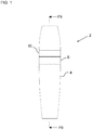
- FIG. 1 is a front plan view of the paint tester according to a first embodiment of the present invention
- FIGS. 2A and 2B are respective top plan and bottom plan views of the paint tester of FIG. 1 ;
- FIG. 3 is an isometric view of the paint tester of FIG. 1 ;
- FIGS. 4A and 4B are respective exploded top front right isometric and exploded bottom front left isometric views of the paint tester of FIG. 1 ;
- FIG. 5 is an enlarged view of the portion of FIG. 4A within the box marked F 5 ;
- FIG. 6 is an enlarged view of the portion of FIG. 4A within the box marked F 6 ;
- FIG. 7 is an enlarged view of the portion of FIG. 4B within the box marked F 7 ;
- FIG. 8 is an enlarged view of the portion of FIG. 4B within the box marked F 8 ;
- FIG. 9 is a sectional view of paint tester of FIG. 1 along the sectional line F 9 ;
- FIG. 10 is an enlarged view of the portion of FIG. 9 within the box marked F 10 .
- components A, B, and C can consist of (i.e., contain only) components A, B, and C, or can contain not only components A, B, and C but also one or more other components.
- the defined steps can be carried out in any order or simultaneously (except where the context excludes that possibility), and the method can include one or more other steps which are carried out before any of the defined steps, between two of the defined steps, or after all the defined steps (except where the context excludes that possibility).
- the term “at least” followed by a number is used herein to denote the start of a range beginning with that number (which may be a range having an upper limit or no upper limit, depending on the variable being defined). For example “at least 1” means 1 or more than 1.
- the term “at most” followed by a number is used herein to denote the end of a range ending with that number (which may be a range having 1 or 0 as its lower limit, or a range having no lower limit, depending upon the variable being defined). For example, “at most 4” means 4 or less than 4, and “at most 40%” means 40% or less than 40%.
- a range is given as “(a first number) to (a second number)” or “(a first number) ⁇ (a second number),” this means a range whose lower limit is the first number and whose upper limit is the second number.
- 25 to 100 mm means a range whose lower limit is 25 mm, and whose upper limit is 100 mm.
- the paint tester 2 comprises a receptacle 4 , a seal cutter 6 , and an applicator 8 .
- the paint tester may also include a cap 10 .
- the receptacle 4 is a preferably elongate container with a base 12 , a wall 14 extending from the base 12 , and a channel 16 , all defining an interior 18 of the receptacle 4 .
- the channel 16 is connected to an upper portion of the wall 14 by a ledge 20 .
- the wall 14 is preferably opaque, to prevent paint 22 held within the receptacle 4 from being exposed to light.
- the wall 14 may be all or partly transparent.
- an opaque covering such as a wrapping, may be included to block light.
- a clear window in the wrapping may be provided, to allow a purchaser to see the true color of the paint 22 .
- the receptacle 4 may have a transparent base 12 , and preferably either an opaque wall 14 or a transparent wall 14 with an opaque covering. This would allow a purchaser to lift up the paint tester 2 and turn it over to see the true color of the paint 22 , but still block light from reaching the paint 22 if the paint tester 2 was stored in an upright position, with the base 12 adjacent to a base of a storage or display box or other surface.
- the wall 14 , base 12 , and channel 16 are preferably formed of a polymer plastic, such as, for example, polypropylene and polyethylene. Other plastics could include PLA or other biodegradable plastics.
- the paint 22 stored inside the paint tester 2 is preferably latex paint.
- an oil-based paint 22 could be stored in the paint tester, preferably with a metal or other lining on the inner surface 24 of the receptacle 4 that resists degradation from oil.
- the channel 16 has channel walls 26 defining a channel space 28 in fluid communication with a remaining interior 18 of the receptacle 4 .
- a seal 30 extends over a channel exit 32 , and provides a fluid tight barrier to the interior 18 of the receptacle 4 .
- the seal cutter 6 preferably has threaded radially interior seal cutter walls 34 , which matingly engage with threaded exterior channel walls 36 .
- the seal cutter 6 has one or more teeth 38 , aligned with and extending in a direction of the seal 30 , but preferably initially spaced from the seal 30 .
- the mating threaded walls 34 , 36 cause the respective rotational motion to also cause linear and downward motion on the seal cutter 6 , downward being in a direction toward the base 12 of the receptacle 4 .
- the one or more teeth 38 on the seal cutter 6 will cut into and break the seal 30 that extends over the channel exit 32 , and thereby break the fluid tight barrier to the interior 18 of the receptacle 4 and the paint 22 stored within.
- the seal cutter 6 When the seal cutter 6 is rotated fully, such that the seal cutter 6 is fully screwed onto the channel 16 and further relative rotation is mechanically prevented, the seal cutter 6 forms a fluid tight barrier with the exterior walls 36 of the channel 16 , while providing an opening to the channel exit 32 .
- the seal cutter 6 is preferably prevented from unscrewing from the channel 16 , and thereby failing to maintain a fluid barrier and allowing unintended paint 22 leakage.
- the receptacle 4 has first ratchet teeth 40 that mate with second ratchet teeth 42 on the seal cutter 6 .
- the respective alignment of the first and second ratchet teeth 40 , 42 allow the seal cutter 6 to only be rotated in one direction relative to the receptacle 4 , and thus prevent unscrewing of the seal cutter 6 .
- the receptacle 4 has first stops 44 and full stops 46 disposed on an exterior of the receptacle adjacent to the threaded exterior channel walls 36 .
- the first stops 44 in the form of breakable tabs 44 , engage with second stops 48 on a radially interior surface of the seal cutter 6 , and resist relative rotation of the seal cutter 6 and receptacle 4 up to a breaking force threshold.
- the tabs 44 would break or fold and allow the seal cutter 6 to continue to rotate around the receptacle 4 .
- the breaking force would be a twisting force or torque of a magnitude large enough to provide substantial tactile feedback, but small enough that an average adult could easily overcome it.
- the breaking force is preferably between 0.1 and 5.0 Nm, more preferably between 0.5 and 3.0 Nm, and most preferably between 1.0 and 2.0 Nm.
- the optional full stops 46 would engage the second stops 48 a given distance of rotation past the first stops 44 , and fully prevent the seal cutter 6 from being over tightened and striping the treads on the threaded interior seal cutter walls 34 and threaded exterior channel walls 36 .
- first stops 44 may be more robust, resisting folding or breaking, and be disposed on a removable stop collar that encircles the exterior of the channel walls 26 .
- the stop collar would be rotationally stationary with respect to the receptacle 4 , but removable, either by peeling off, or pulling up over the channel exit 32 , for example.
- the first and second stops 44 , 48 prevent the seal cutter 6 from being rotated relative to the receptacle 4 a distance sufficient to cut into the seal 30 , until the stop collar is removed.
- the seal cutter 6 has a conduit 50 that is aligned with the channel exit 32 of the receptacle 4 .
- the conduit 50 extends into a crevice 52 defined in an interior of the applicator 8 .
- the conduit 50 preferably extends between one half and three fourths a distance from the applicator base 54 to the applicator top 56 , and a conduit top end 58 defines a plurality of crenulations 60 encircling a conduit exit 62 . Perforations may be used in place of or in addition to the crenulation 60 to help disperse paint 22 from the conduit exit 62 .
- a snap fit is preferably formed between the cap 10 and the seal cutter 6 , when the cap 10 is fully seated on the seal cutter 6 .
- the snap fit is formed with a circumferential ridge 64 on the exterior circumference of the seal cutter 2 and a mating circumferential grove 66 on the interior circumference of the cap 10 .
- This snap fit provides for a fluid tight barrier around the applicator when the cap is fully seated on the seal cutter 6 .
- the ridge 64 may be on the cap 10 and the grove 66 on the seal cutter 6 .
- other fluid tight designs allowing the removable attaching of the cap 10 to the seal cutter 6 may be provided, including mating threaded surfaces.
- the applicator 8 preferably has a tapered shape, allowing for even paint 22 dispersion and a more natural painting motion when a user applies the paint 22 to a surface. As shown in FIG. 9 , for example, at least one width the applicator base 54 is preferably multiple times wider than the applicator top 56 .
- the applicator 8 is preferably made of a porous foam, which allows fluid to pass through from the crevice 52 to an exterior of the applicator.
- the user would first either apply a breaking force to turn the second stops 48 past the tabs 44 , as in one embodiment, or would remove the stop collar 46 , as in another embodiment.
- the seal cutter 6 would then be rotated with respect to the receptacle 4 until one or more seal cutter teeth 38 cut into and break the seal 30 on the receptacle 4 .
- the user would then apply an inward pressure to an exterior surface of a receptacle wall 14 , such as squeezing the wall 14 inwardly with his or her hand, causing paint 22 to flow from the receptacle 4 through the channel exit 32 of the channel, through the conduit 50 defined in the seal cutter 6 , out the conduit exit 62 encircled by crenulations 60 , through pores in the applicator 8 , and onto an exterior surface of the applicator 8 .
- the user would then touch the exterior surface of the applicator 8 to a surface upon which paint 22 is desired, causing the paint 22 previously stored in the interior of the receptacle to attach to the surface upon which paint 22 is desired.
Landscapes
- Engineering & Computer Science (AREA)
- Mechanical Engineering (AREA)
- Physics & Mathematics (AREA)
- Geometry (AREA)
- General Physics & Mathematics (AREA)
- Theoretical Computer Science (AREA)
- Details Or Accessories Of Spraying Plant Or Apparatus (AREA)
- Coating Apparatus (AREA)
Abstract
Description
Claims (19)
Priority Applications (1)
| Application Number | Priority Date | Filing Date | Title |
|---|---|---|---|
| US16/352,235 US11043148B2 (en) | 2019-01-08 | 2019-03-13 | Paint tester |
Applications Claiming Priority (2)
| Application Number | Priority Date | Filing Date | Title |
|---|---|---|---|
| US201962789626P | 2019-01-08 | 2019-01-08 | |
| US16/352,235 US11043148B2 (en) | 2019-01-08 | 2019-03-13 | Paint tester |
Publications (2)
| Publication Number | Publication Date |
|---|---|
| US20200219422A1 US20200219422A1 (en) | 2020-07-09 |
| US11043148B2 true US11043148B2 (en) | 2021-06-22 |
Family
ID=71404472
Family Applications (1)
| Application Number | Title | Priority Date | Filing Date |
|---|---|---|---|
| US16/352,235 Expired - Fee Related US11043148B2 (en) | 2019-01-08 | 2019-03-13 | Paint tester |
Country Status (2)
| Country | Link |
|---|---|
| US (1) | US11043148B2 (en) |
| WO (1) | WO2020146474A1 (en) |
Citations (10)
| Publication number | Priority date | Publication date | Assignee | Title |
|---|---|---|---|---|
| US4659243A (en) | 1985-04-15 | 1987-04-21 | Winson John P | Fountain type applicator for ink or the like and cartridge therefor |
| US4738358A (en) | 1986-11-14 | 1988-04-19 | Kehl Charles W | Paint roller storage container and extractor |
| US6655746B1 (en) | 1997-12-13 | 2003-12-02 | Sterkel Gmbh Pinsel-Und Frabrollerwerk | Paint roller and its production process |
| US20070048066A1 (en) | 2005-08-11 | 2007-03-01 | Geka Brush Gmbh | Application for cosmetic product |
| US20080245314A1 (en) * | 2007-04-05 | 2008-10-09 | Brodowski Thomas | Fluid delivery assembly |
| US7563048B2 (en) * | 2005-06-16 | 2009-07-21 | Platinum Innovations, Inc. | Twist-open dispenser with applicator & method of applying skin care products & method of merchandising paint |
| US20140361016A1 (en) * | 2012-02-23 | 2014-12-11 | Francoise MOREAU | Dispensing and mixing device |
| US9066711B2 (en) * | 2011-11-02 | 2015-06-30 | Adhezion Biomedical, Llc | Applicators for storing sterilizing, and dispensing an adhesive |
| US9688443B2 (en) * | 2012-01-27 | 2017-06-27 | Poly-Clip System Gmbh & Co. Kg | Packaging combination |
| US20170369210A1 (en) | 2016-06-23 | 2017-12-28 | Albea Services | Perforator cap, in particular for a flexible tube |
Family Cites Families (1)
| Publication number | Priority date | Publication date | Assignee | Title |
|---|---|---|---|---|
| US7338227B2 (en) * | 2005-08-29 | 2008-03-04 | Bullivant Todd J | Roller applicator for touch-up system |
-
2019
- 2019-03-13 US US16/352,235 patent/US11043148B2/en not_active Expired - Fee Related
-
2020
- 2020-01-08 WO PCT/US2020/012706 patent/WO2020146474A1/en not_active Ceased
Patent Citations (10)
| Publication number | Priority date | Publication date | Assignee | Title |
|---|---|---|---|---|
| US4659243A (en) | 1985-04-15 | 1987-04-21 | Winson John P | Fountain type applicator for ink or the like and cartridge therefor |
| US4738358A (en) | 1986-11-14 | 1988-04-19 | Kehl Charles W | Paint roller storage container and extractor |
| US6655746B1 (en) | 1997-12-13 | 2003-12-02 | Sterkel Gmbh Pinsel-Und Frabrollerwerk | Paint roller and its production process |
| US7563048B2 (en) * | 2005-06-16 | 2009-07-21 | Platinum Innovations, Inc. | Twist-open dispenser with applicator & method of applying skin care products & method of merchandising paint |
| US20070048066A1 (en) | 2005-08-11 | 2007-03-01 | Geka Brush Gmbh | Application for cosmetic product |
| US20080245314A1 (en) * | 2007-04-05 | 2008-10-09 | Brodowski Thomas | Fluid delivery assembly |
| US9066711B2 (en) * | 2011-11-02 | 2015-06-30 | Adhezion Biomedical, Llc | Applicators for storing sterilizing, and dispensing an adhesive |
| US9688443B2 (en) * | 2012-01-27 | 2017-06-27 | Poly-Clip System Gmbh & Co. Kg | Packaging combination |
| US20140361016A1 (en) * | 2012-02-23 | 2014-12-11 | Francoise MOREAU | Dispensing and mixing device |
| US20170369210A1 (en) | 2016-06-23 | 2017-12-28 | Albea Services | Perforator cap, in particular for a flexible tube |
Non-Patent Citations (1)
| Title |
|---|
| "AkzoNobel wins leading packaging innovation award for Flexa wet tester" (AkzoNobe), Nov. 25, 2016, entire document. |
Also Published As
| Publication number | Publication date |
|---|---|
| US20200219422A1 (en) | 2020-07-09 |
| WO2020146474A1 (en) | 2020-07-16 |
Similar Documents
| Publication | Publication Date | Title |
|---|---|---|
| US11730249B2 (en) | Cosmetic jars with sweep collar | |
| US9167881B2 (en) | Container for storing and displaying a cosmetic product | |
| US3521745A (en) | Mixing package | |
| CN1331712C (en) | Container for a brushable coating composition | |
| US4732287A (en) | Container and applicator for fluids | |
| US2990076A (en) | Closure cap and container neck construction | |
| CN106103295B (en) | Resealable container and closed packaging | |
| ATE464239T1 (en) | DISPENSING CONTAINER FOR FLOWABLE PRODUCTS AND METHOD FOR PRODUCING THE SAME | |
| JPH05506416A (en) | Container and sealing body | |
| MXPA06012860A (en) | Fluid dispensers having removably attached dual applicator assembly. | |
| WO2007030663A2 (en) | Inner container attachable to primary container cap | |
| AU2021414419B2 (en) | Vessel and system for reducing packaging waste | |
| US7044669B2 (en) | Packaging device for a fluid product | |
| US20130025740A1 (en) | Container for dispensing liquid | |
| US11043148B2 (en) | Paint tester | |
| US20220055051A1 (en) | Fluid dispenser | |
| JP7416442B2 (en) | double container | |
| US3467282A (en) | Mixing tube | |
| JP2020055557A (en) | Discharge container | |
| US20160311590A1 (en) | Identification lid wrap | |
| US1918308A (en) | Container | |
| JPH06115563A (en) | Distributing device | |
| JPH0715559U (en) | Discharge container | |
| EP3982785B1 (en) | A hair oil applicator | |
| JP7058510B2 (en) | Laminated foam container |
Legal Events
| Date | Code | Title | Description |
|---|---|---|---|
| FEPP | Fee payment procedure |
Free format text: ENTITY STATUS SET TO UNDISCOUNTED (ORIGINAL EVENT CODE: BIG.); ENTITY STATUS OF PATENT OWNER: SMALL ENTITY |
|
| FEPP | Fee payment procedure |
Free format text: ENTITY STATUS SET TO SMALL (ORIGINAL EVENT CODE: SMAL); ENTITY STATUS OF PATENT OWNER: SMALL ENTITY |
|
| STPP | Information on status: patent application and granting procedure in general |
Free format text: RESPONSE TO NON-FINAL OFFICE ACTION ENTERED AND FORWARDED TO EXAMINER |
|
| STPP | Information on status: patent application and granting procedure in general |
Free format text: RESPONSE TO NON-FINAL OFFICE ACTION ENTERED AND FORWARDED TO EXAMINER |
|
| STPP | Information on status: patent application and granting procedure in general |
Free format text: NOTICE OF ALLOWANCE MAILED -- APPLICATION RECEIVED IN OFFICE OF PUBLICATIONS |
|
| STPP | Information on status: patent application and granting procedure in general |
Free format text: PUBLICATIONS -- ISSUE FEE PAYMENT RECEIVED |
|
| STPP | Information on status: patent application and granting procedure in general |
Free format text: PUBLICATIONS -- ISSUE FEE PAYMENT VERIFIED |
|
| STCF | Information on status: patent grant |
Free format text: PATENTED CASE |
|
| FEPP | Fee payment procedure |
Free format text: MAINTENANCE FEE REMINDER MAILED (ORIGINAL EVENT CODE: REM.); ENTITY STATUS OF PATENT OWNER: SMALL ENTITY |
|
| LAPS | Lapse for failure to pay maintenance fees |
Free format text: PATENT EXPIRED FOR FAILURE TO PAY MAINTENANCE FEES (ORIGINAL EVENT CODE: EXP.); ENTITY STATUS OF PATENT OWNER: SMALL ENTITY |
|
| STCH | Information on status: patent discontinuation |
Free format text: PATENT EXPIRED DUE TO NONPAYMENT OF MAINTENANCE FEES UNDER 37 CFR 1.362 |
|
| FP | Lapsed due to failure to pay maintenance fee |
Effective date: 20250622 |