US11042073B2 - Tunable graphene metamaterials for beam steering and tunable flat lenses - Google Patents
Tunable graphene metamaterials for beam steering and tunable flat lenses Download PDFInfo
- Publication number
- US11042073B2 US11042073B2 US16/268,566 US201916268566A US11042073B2 US 11042073 B2 US11042073 B2 US 11042073B2 US 201916268566 A US201916268566 A US 201916268566A US 11042073 B2 US11042073 B2 US 11042073B2
- Authority
- US
- United States
- Prior art keywords
- graphene
- array
- graphene layer
- layer
- electrolyte
- Prior art date
- Legal status (The legal status is an assumption and is not a legal conclusion. Google has not performed a legal analysis and makes no representation as to the accuracy of the status listed.)
- Active, expires
Links
Images


Classifications
-
- G—PHYSICS
- G02—OPTICS
- G02F—OPTICAL DEVICES OR ARRANGEMENTS FOR THE CONTROL OF LIGHT BY MODIFICATION OF THE OPTICAL PROPERTIES OF THE MEDIA OF THE ELEMENTS INVOLVED THEREIN; NON-LINEAR OPTICS; FREQUENCY-CHANGING OF LIGHT; OPTICAL LOGIC ELEMENTS; OPTICAL ANALOGUE/DIGITAL CONVERTERS
- G02F1/00—Devices or arrangements for the control of the intensity, colour, phase, polarisation or direction of light arriving from an independent light source, e.g. switching, gating or modulating; Non-linear optics
- G02F1/29—Devices or arrangements for the control of the intensity, colour, phase, polarisation or direction of light arriving from an independent light source, e.g. switching, gating or modulating; Non-linear optics for the control of the position or the direction of light beams, i.e. deflection
-
- G—PHYSICS
- G02—OPTICS
- G02F—OPTICAL DEVICES OR ARRANGEMENTS FOR THE CONTROL OF LIGHT BY MODIFICATION OF THE OPTICAL PROPERTIES OF THE MEDIA OF THE ELEMENTS INVOLVED THEREIN; NON-LINEAR OPTICS; FREQUENCY-CHANGING OF LIGHT; OPTICAL LOGIC ELEMENTS; OPTICAL ANALOGUE/DIGITAL CONVERTERS
- G02F2202/00—Materials and properties
- G02F2202/30—Metamaterials
-
- G—PHYSICS
- G02—OPTICS
- G02F—OPTICAL DEVICES OR ARRANGEMENTS FOR THE CONTROL OF LIGHT BY MODIFICATION OF THE OPTICAL PROPERTIES OF THE MEDIA OF THE ELEMENTS INVOLVED THEREIN; NON-LINEAR OPTICS; FREQUENCY-CHANGING OF LIGHT; OPTICAL LOGIC ELEMENTS; OPTICAL ANALOGUE/DIGITAL CONVERTERS
- G02F2202/00—Materials and properties
- G02F2202/36—Micro- or nanomaterials
-
- G—PHYSICS
- G02—OPTICS
- G02F—OPTICAL DEVICES OR ARRANGEMENTS FOR THE CONTROL OF LIGHT BY MODIFICATION OF THE OPTICAL PROPERTIES OF THE MEDIA OF THE ELEMENTS INVOLVED THEREIN; NON-LINEAR OPTICS; FREQUENCY-CHANGING OF LIGHT; OPTICAL LOGIC ELEMENTS; OPTICAL ANALOGUE/DIGITAL CONVERTERS
- G02F2203/00—Function characteristic
- G02F2203/24—Function characteristic beam steering
-
- H01L27/092—
-
- H—ELECTRICITY
- H10—SEMICONDUCTOR DEVICES; ELECTRIC SOLID-STATE DEVICES NOT OTHERWISE PROVIDED FOR
- H10D—INORGANIC ELECTRIC SEMICONDUCTOR DEVICES
- H10D84/00—Integrated devices formed in or on semiconductor substrates that comprise only semiconducting layers, e.g. on Si wafers or on GaAs-on-Si wafers
- H10D84/80—Integrated devices formed in or on semiconductor substrates that comprise only semiconducting layers, e.g. on Si wafers or on GaAs-on-Si wafers characterised by the integration of at least one component covered by groups H10D12/00 or H10D30/00, e.g. integration of IGFETs
- H10D84/82—Integrated devices formed in or on semiconductor substrates that comprise only semiconducting layers, e.g. on Si wafers or on GaAs-on-Si wafers characterised by the integration of at least one component covered by groups H10D12/00 or H10D30/00, e.g. integration of IGFETs of only field-effect components
- H10D84/83—Integrated devices formed in or on semiconductor substrates that comprise only semiconducting layers, e.g. on Si wafers or on GaAs-on-Si wafers characterised by the integration of at least one component covered by groups H10D12/00 or H10D30/00, e.g. integration of IGFETs of only field-effect components of only insulated-gate FETs [IGFET]
- H10D84/85—Complementary IGFETs, e.g. CMOS
Definitions
- Metamaterials are materials engineered at the sub-wavelength scale to have optical properties beyond those available in natural materials, such as enhanced light absorption or transmission, light bending, and negative index of refraction. Plasmons are collective oscillations of charge carriers that allow for light manipulation below the diffraction limit via extreme confinement of electromagnetic fields. These properties of metamaterials and plasmonics have opened up a wide range of promising applications, including surface-enhanced Raman scattering, plasmonic waveguiding, biochemical sensing, and plasmon-enhanced nonlinear optics.
- Graphene a two-dimensional carbon-atom lattice, possesses unique mechanical, electrical and thermal characteristics.
- optics for example, graphene's exceptionally strong and broadband light-matter interaction, extreme Fermi level tunability by electrical gating or chemical doping, high carrier mobility, and high optical nonlinearity have led to many demonstrations of optoelectronic devices, such as high-speed photodetectors for visible to terahertz, high-speed optical modulators with large contrast, and saturable absorbers for mode-locked lasers.
- optoelectronic devices such as high-speed photodetectors for visible to terahertz, high-speed optical modulators with large contrast, and saturable absorbers for mode-locked lasers.
- SPP surface plasmon polaritons
- graphene Compared to conventional metals, graphene features extremely low loss and tunable plasmons that can be confined into an extremely small mode volume ⁇ ( ⁇ /100) 3 and modulated at extremely high frequencies. As an example, this could lead to optical nonlinearities at a few-photon level.
- Embodiments of these technologies include devices made with a comprehensive and iterative approach that enables dramatically improving graphene photonic device properties through closely coupled efforts in systems design, high-quality graphene sample growth and assembly, nanofabrication and sample processing, and measurement-based device modeling.
- graphene plasmons with higher quality factors are achieved by adopting a material assembly geometry of encapsulation of chemical vapor deposition (CVD)-grown graphene in CVD-grown hexagonal boron-nitride (hBN) and applying an optical conductivity variation approach for excitation of graphene plasmons without nanopatterning of the graphene, leveraging new material growth methods and a nanoscale strong electrostatic doping technique.
- CVD chemical vapor deposition
- hBN hexagonal boron-nitride
- Nonreciprocal graphene plasmons and optical isolators, flat optics with graphene metamaterials, and extreme mode-confinement of graphene plasmons and few-photon nonlinear optics take advantage of several phenomena of graphene plasmonics, including nonreciprocal graphene plasmons, the generalized law of refraction and reflection of metamaterials, and the low-power nonlinear optics as a result of the extreme mode confinement by graphene plasmons. They also take advantage of novel simulation methods and an iterative measurement-based device modeling approach. These techniques lead to further embodiments of the present technology, including nanophotonic ultra-thin zoom-lenses, compact and flat LIDAR transmitters, and single photon optical switches.
- Embodiments of the present technology address the grand challenge faced by the field of graphene plasmonics today: limited plasmon quality factor for large-scale samples due to sample assembly and fabrication. Solutions to this problem, combined with closely coupled efforts in iterative device and system designs, open up numerous possibilities for nanophotonic technology in optical communication, optical computing, sensing, imaging, and precision navigation, among other applications. The present technology may impact other fields as well. Improvements in material growth and assembly, nanofabrication, nanoscale doping control technique, and nanoantenna designs may enable breakthroughs in other emerging 2D material applications, such as light-emitting devices, single photon emitters, and optical detectors based on transition metal dichalcogenides (TMDs).
- TMDs transition metal dichalcogenides
- the present technology may take the form of apparatus (e.g., a tunable lens or beam-steering device) with a first electrode on one side of a substrate and an array of unit cells on the other side of the substrate.
- Each unit cell in the array of unit cells comprises a layer of hexagonal boron-nitride (hBN) disposed on the substrate, a graphene layer disposed on the layer of hBN and having a carrier mobility substantially equal to or greater than 10,000 cm 2 /(V ⁇ s), and a second electrode disposed in electrical communication with the graphene layer.
- hBN hexagonal boron-nitride
- the first and second electrodes apply a voltage across the graphene layer that shifts a Fermi level of the graphene layer, thereby changing an amplitude and/or phase of at least a portion of an incident beam of light. This causes the array of unit cells to spatially modulate the incident beam of light.
- the array of unit cells may form a one-dimensional (1D) array of unit cells configured to steer the incident beam of light in an arbitrary direction.
- the array of unit cells may include a two-dimensional (2D) array of unit cells configured to change a divergence of the incident beam of light.
- a first group of unit cells in the 2D array of unit cells may form a first ring and a second group of unit cells in the 2D array of unit cells form a second ring concentric with the first ring.
- the graphene layer in at least one unit cell in the array of unit cells may be patterned to from an array of graphene nanostructures.
- the unit cell may include an array of metal strips, each of which is disposed next to a corresponding graphene nanostructure in the array of graphene nanostructures.
- the unit cell can also include an array of metal nanoantennas disposed on the layer of graphene and having hotspots at graphene nanostructures in the array of graphene nanostructures to excite and couple to localized graphene plasmons.
- the unit cell may include hBN disposed between the graphene nanostructures in the array of graphene nanostructures.
- the graphene layer may include alternating regions of a first carrier concentration and a second carrier concentration different from the first carrier concentration. These alternating regions can be at a pitch substantially equal to or greater than 15 nm. A difference between the first carrier concentration and the second carrier concentration may be substantially equal to or less than 10 14 cm ⁇ 2 .
- a given unit cell in the array of unit cells can include another layer of hBN disposed on the graphene layer, a periodic array of metallic slits disposed on the graphene layer, a two-arm Archimedean spiral antenna, and/or a nanoantenna comprising concentric metallic rings electrically connected to each other.
- the graphene layer may be formed as or include a graphene nanodisk disposed at a center of the Archimedean spiral antenna or nanoantenna.
- the substrate may be a layer in a complementary metal-oxide-semiconductor (CMOS) stack. If so, then at least a portion of the second electrode can extend into the CMOS stack. And the first electrode may be at least part of a metal layer in the CMOS stack.
- CMOS complementary metal-oxide-semiconductor
- Another apparatus embodying the present technology includes a substrate, a graphene layer (e.g., with a carrier mobility of at least about 10,000 cm 2 /(V ⁇ s)) disposed on the substrate, an electrolyte disposed on the graphene layer, a first electrode in electrical communication with the graphene layer, a second electrode in electrical communication with the electrolyte, and a patterned dielectric layer between the graphene layer and the electrolyte.
- the pair of electrodes applies a bias voltage across the graphene layer and the electrolyte that causes ions in the electrolyte to migrate toward the graphene layer.
- the patterned dielectric layer screens at least a portion of the graphene layer from ions in the electrolyte, thereby creating a spatially varying carrier concentration in the graphene layer.
- This spatially varying carrier concentration spatially modulates an optical conductivity of the graphene layer.
- the patterned dielectric layer can be patterned in a periodic array such that the spatially varying carrier concentration varies periodically with the periodic array.
- FIG. 1A shows universal 2.3% optical absorption by a uniform sheet of monolayer graphene.
- FIG. 1B shows enhanced absorption in certain spectral ranges by a nanostructured sheet of monolayer graphene subject to an applied voltage.
- FIG. 2 shows example devices fabricated with stacks of monolayer hBN and graphene grown by chemical vapor deposition (CVD) and transferred by the van der Waals assembly technique onto a substrate.
- CVD chemical vapor deposition
- FIG. 3A is a diagram of a graphene device with nanoscale electrolyte gates.
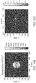
- FIG. 3B shows SEMs of example fabricated PMMA masks on graphene with nanoscale dimensions.
- FIG. 3C is a plot of simulated charge carrier density for a single metal-dielectric split gating junction and an electrolyte-PMMA-mask gating junction like those in the device of FIG. 3A .
- FIG. 3D is a plot of simulated in-plane electric field intensity E in-plane for a single metal-dielectric split gating junction and an electrolyte-PMMA-mask gating junction like those in the device of FIG. 3A .
- FIG. 3E is a plot of the capacitance of an example PMMA-mask/electrolyte system like the one shown in FIG. 3A .
- FIG. 3F shows a schematic (right) and a photograph (left) of a compact graphene thermopile coated with a patterned PMMA mask.
- FIG. 4A is an optical image of a graphene p-n junction device, with the p-n junction defined by a PMMA mask as in the device shown in FIG. 3A .
- FIG. 4C is a plot of resistance of the graphene p-n junction device of FIG. 4A as a function of the top gate voltage V TG and the back gate voltage V BG .
- FIG. 4D is a plot of photovoltage of the graphene p-n junction device of FIG. 4A as a function of the top gate voltage V TG and the back gate voltage V BG .
- FIG. 5A shows optical absorption spectra for nanoscale electrolytically gated graphene absorbers with different dimensions.
- FIG. 5B shows absorption spectra of a nanoscale electrolytically gated graphene absorber via electrostatic gating of graphene with Fermi levels from 0.4 eV to 0.8 eV.
- FIG. 6A shows an optical microscope image of an optical conductivity modulation devices enabled by nanopatterning electrolyte gates.
- FIG. 6B shows a scanning electron micrograph (SEM) of devices like those in FIG. 6A with cross-linked PMMA masks prior to electrolyte deposition.
- FIG. 6C shows Fourier-transform infrared (FTIR) transmission spectra of reference devices with etched graphene nanostructures with different dimensions and different graphene Fermi levels (gate voltages).
- FTIR Fourier-transform infrared
- FIG. 6D shows finite-difference time-domain (FDTD) simulated transmission spectra of optical conductivity modulation devices. Each 2D plot assumes constant graphene Fermi level on one side of the junction and varies graphene Fermi level on the other side of the junction.
- FDTD finite-difference time-domain
- FIG. 7A shows a flat, tunable graphene lens suitable for use in a smartphone camera.
- FIG. 7B shows a flat, tunable graphene beam-steering device suitable for use in a lidar for a self-driving car.
- FIGS. 8A-8L show different unit cells for tunable flat optics made with graphene metamaterials.
- FIG. 8M shows graphene unit cells in a CMOS stack
- FIG. 9A shows a tunable beam-steering device with a one-dimensional array of graphene metamaterial unit cells.
- FIG. 9B shows a tunable lens with graphene metamaterial unit cells arranged in a two-dimensional pattern.
- FIG. 10A shows an excitation cross section of a single graphene nanodisk when a plasmonic mode is excited.
- FIG. 10B is an intensity profile of an electric field in an x-y plane scattered by a graphene nanodisk when a plasmonic mode is excited at a wavelength of 7 ⁇ m.
- FIG. 10C is an intensity profile of an electric field in an x-z plane scattered by a graphene nanodisk when a plasmonic mode is excited at a wavelength of 7 ⁇ m.
- FIG. 11A illustrates nonlinear frequency conversion with an optically nonlinear graphene nanostructure.
- FIG. 11B illustrates saturable absorption by an optically nonlinear graphene nanostructure.
- FIG. 11C illustrates few-photon cross-modulation by an optically nonlinear graphene nanostructure.
- FIG. 12A shows a bowtie graphene nanoantenna with a triangular metal plasmonic nanoantenna that induces a plasmonic mode and concentrates a strong electromagnetic field in a graphene nanodisk.
- FIG. 12B is a plot of the Purcell enhancement factor versus wavelength for different bowtie nanoantennas (one example shown in FIG. 12A ).
- FIG. 13A illustrates splitting of a plasmon resonance in a patterned graphene ribbon due to the current-induced Doppler effect.
- FIG. 13B shows an on-chip optical isolator based on a Mach-Zehnder interferometer and relying on the plasmonic Doppler effect.
- the present technology includes several approaches for metamaterials and plasmonics in graphene that provide and exploit high-quality graphene grown with chemical vapor deposition (CVD).
- CVD chemical vapor deposition
- approaches for metamaterials and plasmonics in graphene that provide and exploit high-quality graphene grown with chemical vapor deposition (CVD).
- CVD chemical vapor deposition
- hBN hexagonal boron-nitride
- a higher carrier mobility e.g., a carrier mobility of 10,000 cm 2 /(V ⁇ s) or higher
- a nanoscale 2D material doping technique that enables plasmon excitation without patterning the graphene (the patterning process usually degrades graphene's quality and mobility by one to two orders of magnitude due to harsh environment during etching and edge scattering in the patterned sample)
- FIGS. 1A and 1B illustrate this voltage-tunable enhanced absorption.
- FIG. 1A shows the universal 2.3% absorption of a non-structured graphene sheet.
- FIG. 1B shows perfect absorption by a nanostructured graphene sheet in different spectral regions when a variable voltage is applied to the nanostructured graphene sheet.
- the spectral range of the nanostructured graphene sheet's enhanced absorption can be tuned by tuning the applied voltage. This varies the Fermi level of the nanostructured graphene sheet.
- the absorption can occur over a wide range of wavelengths, from the visible to the infrared.
- this mismatch may arise from the low carrier mobility of graphene after the etching step in the nanostructure fabrication process and the edge scattering from patterned graphene nanostructures that is not considered in numerical electromagnetic simulations.
- the graphene metamaterials with high quality factors disclosed here address these two causes of low-quality graphene plasmons using three techniques: (1) growing or transferring graphene on hBN to increase carrier mobility, (2) exciting plasmonic modes by creating periodic optical conductivity variation patterns in a continuous sheet of graphene, and (3) growing an in-plane, lattice-matched graphene/hBN heterostructure with well-defined graphene edges to reduce scattering loss from rough edges.
- hBN can be grown in monolayer single-crystalline flakes with sizes up to 50 ⁇ m and continuous polycrystalline films that are centimeters in size have been synthesized.
- CVD graphene on CVD hBN can be transferred using a dry transfer method to avoid the strain caused by trapped water bubbles between graphene and hBN surfaces typically seen in wet transfer methods.
- Synthesis of large-area graphene and other 2D materials with high carrier mobility can be realized in the growth of multilayer hBN as well as uniform thickness single-layer hBN that is centimeters by centimeters in size. This is a dramatic increase in size from exfoliated samples (e.g., 10 ⁇ m ⁇ 10 ⁇ m) of graphene, providing high-quality large-area graphene samples for experiments in the mid-infrared and terahertz, where most applications of graphene plasmonics lie.
- encapsulating the graphene in hBN reduces contamination of the graphene by charge impurities, and the uniform thickness of hBN provides a flat substrate for graphene that largely prevents the wrinkles and tearing of graphene typically seen in CVD samples.
- FIG. 2 shows an example of a CVD hBN-encapsulated graphene device 200 fabricated with graphene and hBN grown by chemical vapor deposition (CVD) and transferred by the van der Waals assembly technique onto a dielectric substrate 210 , such as SiO 2 , SiN x , CaF 2 , or intrinsic Si.
- the device 200 forms a metasurface with several unit cells 202 arranged in a one-dimensional array on the substrate 210 and connected to electrodes 250 and 260 .
- a layer of metal or doped semiconductor (not shown) is deposited to the back side of the substrate 210 to serve as a gate electrode.
- the unit cells 202 can be arranged in other patterns, including two-dimensional arrays, as explained below.
- Applying a voltage to a unit cell 202 with the corresponding electrodes changes the Fermi level of the graphene in the unit cell 202 , thereby changing the unit cell's absorption (e.g., from low absorption at a particular wavelength to high absorption at that wavelength).
- each unit cell 202 includes a graphene layer 230 sandwiched between a lower hBN layer 220 and an upper hBN layer 240 .
- the graphene layer 230 is grown or transferred on the lower hBN layer 220 , it has a carrier mobility of 10,000 cm 2 /(V ⁇ s) (for monolayer hBN) to even 24,000 cm 2 /(V ⁇ s) (for multilayer hBN).
- These hBN/G/hBN stacks 202 can be used to study the confinement of acoustic plasmons in graphene 230 .
- the observation of atomically thin plasmon field confinement in the few-layer hBN on top of graphene has been shown to be the tightest plasmon confinement ever observed, demonstrating the ultimate limit of plasmon field confinement in any material system.
- High quality factors for graphene plasmons in graphene metasurfaces can also be maintained by creating periodic optical conductivity variation patterns in a continuous sheet of graphene.
- This periodic conductivity variation pattern can be realized at the nanoscale with a high conductivity contrast without the edge scattering that occurs in patterned graphene nanostructures. It allows for electrostatic doping of graphene at record high Fermi levels (e.g., >1 eV) with an unprecedentedly high spatial resolution (e.g., sub-10 nm). These are both orders of magnitude improvement on the state-of-the-art doping techniques and could push the plasmonic resonance wavelength of graphene into the near-infrared or even visible range.
- FIGS. 3A-3D illustrate aspects of a device 300 with a continuous sheet of graphene 330 that has a spatial carrier density variation pattern.
- FIG. 3A shows the device 300 itself, with the graphene layer 330 between a layer 340 of solid polymer electrolyte, such as PEO/LiClO 4 , and a silicon dioxide layer 320 on a silicon substrate 310 .
- the graphene layer 330 can be grown or transferred by CVD on an hBN monolayer (not shown) on the silicon dioxide layer 330 .
- growing or transferring the graphene layer 330 on an hBN monolayer can yield a graphene layer that has fewer impurities, a larger wrinkle-free area, and a carrier mobility of 10,000 cm 2 /(V ⁇ s) or higher.
- a patterned dielectric 350 such as a layer of electron-beam (e-beam) over-exposed, cross-linked poly(methyl methacrylate) (PMMA), covers part of the graphene layer 330 and is covered by the electrolyte layer 340 .
- the patterned dielectric 350 has a thickness of about 10 nm to about 500 nm and can be patterned into nanostructures of different shapes, including circles, ribbons, ellipses, or even rectangular waveguide and circular ring resonator shapes. These nanostructures can be arranged in one or two dimensions with feature sizes all the way from about 15 nm to about micrometer-sized or larger. In FIG.
- the patterned dielectric 350 is patterned in an array of discs on a square lattice.
- Other patterned dielectrics may be patterned into one-dimensional arrays of nanoribbons, two-dimensional arrays on different lattices (e.g., rectangular or hexagonal lattices), or aperiodic, random, or sparse arrays.
- FIG. 3B shows scanning-electron-micrographs (SEMs) of two examples of PMMA mask on graphene with nanometer feature size and different geometries, including disks (upper right image) and ribbons (upper left image and lower image).
- the disks have a radius of about 50 nm, and the ribbons are about 29 nm wide and 118 nm tall with a period of about 60 nm.
- the patterned dielectric 350 screens ions in electrolytes. This creates a spatially varying carrier concentration in the graphene layer 330 as carriers within the graphene redistribute themselves in response to the carrier movement in the electrolyte 340 under the applied voltage.
- the patterned dielectric 350 prevents the mask-protected areas of the graphene layer 330 from being modulated by the electrolyte gate. This effectively create lithographically-defined local electrolyte gates with geometries and feature sizes determined by the pattern etched into the patterned dielectric layer. Because the patterned dielectric layer can be etched lithographically, this means that the gates can be patterned with feature sizes down to several nanometers.
- FIG. 3C shows finite-element simulations of both an electrolyte-PMMA junction like those in FIG. 3A and a conventional metal-dielectric split gate junction.
- FIG. 3C shows a much sharper carrier density transition for an electrolyte-PMMA junction compared to a conventional metal-dielectric split gate junction, with a junction sharpness of as low as 10 nm and a local carrier concentration contrast of more than 10 14 cm ⁇ 2 .
- FIG. 3D shows an in-plane electric field intensity of 600 MV/m at the vicinity close to the graphene boundary.
- FIG. 3E is a plot of the capacitance of an example PMMA-mask/electrolyte system extracted from capacitance-voltage (CV) measurements (dots) and fitted to a model (curve) as a function of the mask thickness.
- the area between the two dotted lines indicates the 95% confidence interval of the fitting.
- the inset of FIG. 3E shows measured CV curves for samples with different PMMA mask thicknesses.
- the arrows indicate the voltage sweeping directions.
- FIG. 3F shows a schematic (right) and a photograph (left) of a compact graphene thermopile 390 with wedges of resist (PMMA) 394 .
- the resist 394 When viewed from the top (as in FIG. 3F ), the resist 394 creates a pinwheel-like pattern of exposed and coated wedges of graphene.
- the wedges can be represented electrically as alternating impedance and voltage sources (V 1 , R 1 , V 2 , R 2 , and so on) connected in series.
- the dashed circles indicate the size of the thermopile 390 .
- the solid circle at lower right in the left inset indicates the full-width half-maximum (FWHM) of the laser spot (about 30 ⁇ m) used to make the measurements.
- FWHM full-width half-maximum
- FIGS. 4A-4E show tests of full-range carrier density control of a graphene p-n junction created by depositing a patterned PMMA layer on half of a graphene channel and covering the entire channel and the patterned PMMA layer with an electrolyte.
- FIG. 4A is an optical photograph of the graphene p-n junction, which is tuned by applying a voltage to gold (Au) electrodes. The white dashed lines indicate the shape of the graphene channel and the green region is the cross-linked PMMA mask. The entire device is then covered with solid polymer electrolyte PEO/LiClO 4 (not shown in the picture).
- FIG. 4A is an optical photograph of the graphene p-n junction, which is tuned by applying a voltage to gold (Au) electrodes.
- the white dashed lines indicate the shape of the graphene channel and the green region is the cross-linked PMMA mask.
- the entire device is then covered with solid polymer electrolyte PEO/LiClO
- FIG. 4B shows a spatial photovoltage map of the graphene p-n junction created with near-infrared confocal microscope with a spot size indicated by the circle at lower left.
- the darker regions illustrate strong photovoltage signals generated at the p-n junction and the graphene/metal junction.
- the polarity of the photovoltage signal at the p-n junction is opposite the polarity of the photovoltage signal at the graphene/metal junction.
- FIGS. 4C and 4D illustrate the graphene p-n junction's voltage-tunable resistance and the voltage-tunable photoresponse generated at the interface of separately doped graphene regions, respectively.
- FIGS. 5A and 5B show simulated optical absorption spectra for an example graphene metamaterial with conductivity variation with a single atomic layer of graphene.
- the conductivity variation was patterned as disks with a radius of 50 nm on a square lattice, as shown in the insets of FIGS. 5A and 5B .
- Each trace in FIG. 5A represents a different lattice pitch, from 160 nm to 220 nm in increments of 20 nm.
- Each trace in FIG. 5B represents a different graphene Fermi level, from 0.4 eV to 0.8 eV.
- FIGS. 5A and 5B show that this graphene metamaterial exhibits spectrally tunable enhanced optical absorption.
- the geometry and dimensions of the periodic doping pattern can be optimized to achieve coherent perfect absorption.
- the resonant wavelength of the graphene plasmonic modes can vary across a large wavelength range when graphene's Fermi level is tuned by changing the lattice pitch, as shown in FIG. 5A , and tuned dynamically by applying an electric voltage to the gates.
- FIG. 5B shows a wavelength blueshift of more than 2 ⁇ m as the Fermi level of graphene is increased from 0.4 eV to 0.8 eV.
- FIGS. 6A-6D illustrate optical conductivity spatial modulation devices with high carrier mobility and spatially varying optical conductivity as well as measurements of those devices.
- FIG. 6A is an optical microscope image of a device like the one shown in FIG. 2 (without hBN encapsulation) with a PMMA mask on the graphene and a spin-coated electrolyte layer on the graphene and PMMA mask as in FIG. 3A .
- FIG. 6B shows SEM images of different devices with cross-linked PMMA masks prior to electrolyte deposition. The insets at bottom show close-ups of some of the devices.
- the devices shown in FIGS. 6A and 6B were made on CVD graphene transferred on a SiO 2 substrate.
- Nanoribbon-shaped spatial modulation of optical conductivity is enabled by the nanopatterned electrolyte gates with various dimensions (widths of 30 nm to 80 nm as shown in FIG. 6B ). These devices had plasmonic resonances in the 4-10 ⁇ m range, according to finite difference time domain (FDTD) simulations.
- FDTD finite difference time domain
- FIG. 6C shows FTIR transmission spectra of reference devices with etched graphene nanostructures with different dimensions and different graphene Fermi levels (gate voltages).
- FIG. 6D shows transmission spectra, simulated with FDTD, of a graphene periodic optical conductivity modulation device.
- the left plot in FIG. 6D shows the transmission spectrum for a Fermi level of 1 eV on one side of the periodic junction a variable Fermi level on the other side of the junction.
- the right plot in FIG. 6D shows the transmission spectrum for a Fermi level of 0.4 eV on one side of the periodic junction a variable Fermi level on the other side of the junction.
- the graphene nanostructures have poorly defined edges, these edges can cause roughness-related scattering loss.
- the graphene nanostructures can first be defined on copper foils by a standard e-beam lithography and reactive-ion-etch process. The edge roughness is then reduced by another CVD step that transforms the poorly-defined edges into well-defined armchair or zigzag edges.
- This approach as an alternative to the optical conductivity modulation approach disclosed above with the electrolyte nanopatterning technique, allows a simpler geometry where the optical disruption of the electrolyte and the resist mask above the graphene plasmonic metamaterials can be eliminated.
- FIGS. 7A and 7B show flat optics using the graphene metamaterials disclosed herein for focusing and steering light without any moving parts.
- FIG. 7A shows a tunable flat lens made of graphene material (top) whose focus can be changed by changing the applied voltage. This type of lens could replace conventional optical zoom lenses like the mobile phone cameras shown at the bottom of FIG. 7A . The replacement lens could be much thinner and would not need any moving parts.
- FIG. 7B shows a graphene metamaterial beam-steering device (top) that could replace a scanning galvanometer in a laser radar (LIDAR) system, e.g., in a self-driving car (bottom) or another autonomous vehicle.
- LIDAR laser radar
- Changing the Fermi level of the graphene with an applied voltage changes the direction of the graphene metamaterial beam-steering device's output. This device steers the beam in one dimension (e.g., in a plane roughly parallel to the ground), but other devices may steer beams in two dimensions.
- Metasurfaces include optical scatterers, such as arrays of optical metal antennas or other resonators.
- metal-based metasurfaces may be constrained by their inherent plasmonic frequency, so their working wavelength is limited, and they are passive devices that cannot be dynamically controlled.
- Metamaterials based on graphene (including those disclosed here), on the other hand, enable full dynamic tunability across a large wavelength range thanks to their large variation of optical conductivity by electrical gating, opening up numerous new possibilities for active dynamic photonic devices for a broad range of wavelengths from visible to terahertz.
- nanoscale electrolyte doping of graphene as shown in FIG. 3A and described above can be used to produce graphene metamaterials for flat optics.
- These graphene metamaterials may be periodically or aperiodically doped in ribbon, cut-wire, or nanoantenna geometries.
- Other approaches including in-plane graphene/hBN heterostructure with nanoresonator patterns and graphene nanoresonators coupled with metal nanoantennas can be used to produce voltage-tunable metamaterials as well. They can be used to steer and bend light possibly due at least in part to their improved graphene plasmon quality factor.
- FIGS. 8A-8L show several geometries for a unit cell in a reconfigurable graphene metasurface device.
- FIG. 8M shows how these unit cells can be fabricated in a CMOS process.
- Each unit cell in the device can be considered an optical resonant subwavelength antenna that can interact with and scatter incident light waves with certain amplitude and phase.
- the unit cells can be combined in various ways to generate far-field radiation patterns produced by the interference of the individual radiation patterns of the unit cells and can be calculated via the antenna array theory.
- each of these unit cells can be arranged in a one-dimensional periodic array (e.g., as in FIG. 2 ), a two-dimensional array, or any other suitable pattern.
- Two applications, a beam-steering device and a planar focusing lens, are shown in FIGS. 9A and 9B , respectively.
- FIG. 8A shows a unit cell 800 a with graphene nanoribbons 830 a on one side of a silicon nitride substrate 820 that is about 1 ⁇ m thick and is supported by a silicon substrate 822 .
- These graphene nanoribbons 830 a (and the graphene in each of the other unit cells shown in FIGS. 8A-8L ) may be grown or transferred on a monolayer or multi-layer of hBN 824 and, optionally, encapsulated with one or more additional layers of hBN as shown in FIG. 2 .
- the other side of the substrate 820 is coated with a thin layer of gold 810 .
- This gold layer 810 serves as both a reflector that reflects light incident on the graphene side of the unit cell 800 a and a back-gate electrode.
- the unit cell 800 a (and each of the other unit cells shown in FIGS. 8A-8L ) may include one or more other electrodes (not shown) on the graphene side of the unit cell 800 a . Applying a voltage across the graphene layer 830 a with these electrodes modulates the unit cell's reflectivity as explained in greater detail below.
- FIG. 8B shows a unit cell 800 b with a uniform layer of graphene 830 b on the HBN layer 824 one side of the substrate 820 and a PMMA mask 850 b on the graphene 830 b .
- An electrolyte 840 b covers the PMMA mask 850 b and the portions of the graphene 830 b exposed through the PMMA mask 850 b .
- the PMMA mask 850 b is patterned into a one-dimensional array of nanoribbons, creating a corresponding one-dimensional spatial variation in the optical conductivity of the graphene as explained above with respect to FIGS. 3A-3D .
- the spatial variation in the conductivity can be changed by applying a voltage across the unit cell 800 b with the back electrode 810 and other electrodes like those shown in FIG. 3A .
- FIG. 8C shows a unit cell 800 c with a uniform graphene layer 830 c on the HBN layer 824 and coated with gold nanoribbons 860 c .
- These nanoribbons 860 c are arranged in a periodic one-dimensional array and modulate the optical conductivity of the unit cell 800 c .
- Other nanoribbon arrangements are also possible; for example, the nanoribbons could form an array that is linearly chirped in nanoribbon width, pitch, or both to produce a voltage-tunable prismatic effect.
- the nanoribbons could also be arranged in a quadratically chirped array to form a cylindrical Fresnel lens with a voltage-tunable focus in one dimension.
- FIG. 8D shows a unit cell 800 d with an in-plane graphene/hBN heterostructure on the substrate 820 .
- the in-plane graphene/hBN heterostructure comprises alternating ribbons or strips of graphene 830 d and hBN 870 .
- the graphene nanostructures can first be defined on copper foils by an e-beam lithography and reactive-ion-etch process. The edge roughness is then reduced by another CVD step that transforms the poorly-defined edges into well-defined armchair or zigzag edges. A layer of hBN is then grown to fill the gap between the graphene nanostructures.
- the carrier concentration in graphene can be modulated by applying a voltage across the back-gate electrode 810 on one side of the substrate 820 and another electrode 812 on the other side of the substrate 820 .
- FIGS. 8E-8I show examples of graphene nanostructures coupled to metallic plasmonic nanoantennas.
- the metallic nanoantennas facilitate the excitation of graphene plasmons and enhance the localized field surrounding the graphene plasmonic nanostructures.
- FIG. 8E shows a unit cell 800 e with a metallic plasmonic metasurface (here, gold nanoribbons 830 e ) with graphene 860 e as an active load.
- the graphene 860 e is patterned into strips or nanoribbons that are interleaved with the gold nanoribbons 830 e.
- FIG. 8F shows a unit cell 800 f with square graphene nano-patches 830 f coupled to rectangular metallic plasmonic antennas 860 f made of gold.
- FIG. 8G shows a unit cell 800 g with a graphene “fishnet” 830 that defines exposed squares of substrate 810 on a square lattice.
- the unit cell 800 g includes rectangular gold plasmonic antennas 860 g arranged diagonally on each exposed substrate square.
- FIG. 8H shows a unit cell 800 h with a graphene nanodisk 830 h at the center of a gold bull's eye nanoantenna 860 h.
- FIG. 8I shows a unit cell 800 i with a graphene nanodisk 830 i coupled to gold Archimedean spiral antennas 860 i that terminate at the graphene nanodisk 830 i.
- FIGS. 8J-8L show examples of metallic plasmonic structures whose optical response can be dynamically tuned by changing the Fermi level of the graphene underneath these structures.
- FIG. 8J shows unit cells 800 j with metallic triangular plasmonic metasurfaces 860 j with graphene squares 830 j as active loads.
- Each metallic triangular plasmonic metasurface 860 j includes an isosceles triangle with a different apex angle and orientation. The triangles on the top row have the largest apex angles, the triangles in the left column point up, and the triangles in the right column point down.
- These unit cells 800 j can be arranged to generate a desired phase pattern for a specific application, such as a zoomable lens or beam-steering device.
- FIG. 8K shows unit cells 800 k with metallic Vee-shaped plasmonic metasurfaces 860 k with graphene squares 830 k as active loads.
- the metallic Vee-shaped plasmonic metasurfaces 860 k includes Vees with different apex angles and orientations. The Vees on the top row have the smallest apex angles, the Vees in the left column point up, and the Vees in the right column point down.
- These unit cells 800 k can be arranged to generate a desired phase pattern for a specific application, such as a zoomable lens or beam-steering device.
- FIG. 8L shows a unit cell 800 l with metallic unconnected rectangular loop plasmonic metasurfaces 860 l with graphene squares 830 l as an active load.
- the unconnected metallic rectangular loop plasmonic metasurfaces 860 l includes unconnected or broken rectangles with different aspect ratios, “break” or disconnection locations, and lateral dimensions.
- These unit cells 800 l can be arranged to generate a desired phase pattern for a specific application, such as a zoomable lens or beam-steering device.
- FIG. 8M illustrates unit cells 800 m made within a CMOS platform.
- the graphene 830 m in the unit cells 800 m is formed on top of an oxide layer 898 , which is in turn on a CMOS stack 890 .
- the graphene 830 m in each unit cell 800 m is electrically connected to metal pads (electrodes) 896 through vertical contacts (interface vias) 894 .
- the vertical contacts 894 connect to separate metal layers 892 in the CMOS stack 890 .
- Each unit cell 800 m is controlled by a global, uniform oxide gate (e.g., metal layer 893 in the CMOS stack), and a different contact voltage, enabling locally varying gate voltages.
- FIG. 9A shows a one-dimensional beam-steering device 902 with an array of unit cells 900 n on the same substrate 920 .
- the unit cells 900 a are controlled by a common back gate electrode 920 and individual electrodes 914 .
- Electrodes 914 apply potentials V 1 through V 5 to the unit cells 900 a . These potentials can be the same or different (e.g., linearly ramped) and control the amplitude and phase of an incident beam of light 901 .
- a number of applications including beam steering, beam focusing, perfect absorption, perfect reflection, polarization control, super-resolution lens, and “cloaking” can be achieved.
- the applied voltages form a voltage gradient that causes the beam of light 901 to reflect at angle that is less than the angle of incidence. Changing the voltages changes the angle of reflection, steering the beam of light 901 , and may also change the reflectivity at certain wavelengths.
- FIG. 9B shows a voltage-tunable planar focusing lens 904 .
- the lens 904 includes graphene metasurface unit cells 900 b arranged in rings 906 that form a Fresnel lens pattern.
- the unit cells 900 b are on a multi-layer CMOS stack with a silicon nitride or silicon dioxide layer 986 , a first metal layer 984 , a dielectric layer 982 , and a second metal layer 980 . Vias (not shown) connect the electrodes in the unit cells 900 b to one of the metal layers for applying voltages to the unit cells 900 b , e.g., as in FIG. 8M .
- Each unit cell 900 b is controlled by a voltage V ij that determines the amplitude and phase of the light reflected by the unit cell 900 b .
- Each phase setting causes the lens 904 to focus a particular wavelength of light at a different focal distance away. Changing the voltage (phase) configuration changes the lens's focal length.
- FIGS. 10A-10C illustrate simulations of the extreme mode confinement ability of a graphene nanodisk. These simulations were based on the boundary element method.
- FIG. 10A shows the excitation cross section of graphene nanodisk with a diameter of 100 nm (inset) when a plasmonic mode is excited.
- FIGS. 10B and 10C show the scattered electric field intensity in different planes around a 100 nm diameter graphene nanodisk corresponding to the plasmonic mode at a free space wavelength of 7 ⁇ m. From the side view of the disk, shown in FIG. 8C , the field is strongly confined to the surface of the disk and its intensity can be enhanced by as high as four orders of magnitude on the edge of the disk.
- a mid-infrared plane wave excitation of 7 mW for a laser focused to a 10 ⁇ m radius spot corresponds to an incident field amplitude of about 10 5 V/m. With a 100 times enhancement in field amplitude, this results in a 10 7 V/m electric field, which is the same as predicted by theoretical calculations.
- s-SNOM scanning type near-field optical microscope
- dielectric gratings require a large coupling length for efficient excitation, which in turn requires a large plasmon propagation length that is hard to achieve (on the order of the free-space wavelength).
- the coupling efficiency between plasmons and photons has as of yet been extremely low.
- FIGS. 12A and 12B illustrate a plasmonic nanoantenna device 1200 that addresses the challenges associated with coupling light from free space into a graphene nanodisk.
- FIG. 12A shows the device 1200 , which includes a graphene nanodisk 1230 with a diameter of 100 nm at the center of a bowtie-shaped metal nanoantenna 1220 .
- a dielectric substrate 1210 supports the graphene nanodisk 1230 and the bowtie-shaped metal nanoantenna 1220 .
- An incident single photon is coupled into the graphene nanodisk 1230 through the metal plasmonic nanoantenna 1220 , inducing plasmonic mode and concentrating strong electromagnetic field in the graphene nanodisk.
- FIG. 12A shows the device 1200 , which includes a graphene nanodisk 1230 with a diameter of 100 nm at the center of a bowtie-shaped metal nanoantenna 1220 .
- FIG. 12B shows the Purcell enhancement factor for the device 1200 in FIG. 12A (top trace) and for several other nanoantenna designs, which have large bandwidths (Q ⁇ 10).
- the bow-tie design in FIG. 12A has a maximum Purcell enhancement of over 350 at a wavelength of about 640 nm, to produce near-100% light absorption from free space into the graphene disk 1230 .
- the nanoantennas can themselves be made of graphene.
- the dynamic voltage tunability of graphene's Fermi level can allow maximum overlap at all time between the bow-tie antenna's Purcell enhancement envelope and graphene nanodisk's plasmonic modes.
- the graphene plasmon simulation can also take advantage of the boundary element method (BEM) of simulating graphene plasmons, which has been shown to reduce the computational complexity of the typically time-consuming simulation techniques.
- Custom codes can be developed for graphene single nanodisk and nanodisk arrays and can be extended to more complex geometries such as graphene nanoantennas as well. These techniques provide a promising solution to the photon-plasmon coupling problem and creates an opportunity to explore and exploit the plasmon blockade phenomenon in graphene nanodisks as well as other nonlinear optical processes that typically only occur at extremely high pumping powers.
- the high-quality graphene plasmons of Technique 1 open up numerous opportunities in tunable plasmon physics that are currently not possible. One of them is the exciting possibility of observing the quasi-relativistic Doppler effect for graphene plasmons propagating along a nanoribbon.
- Non-reciprocity in materials is typically induced by breaking the time-reversal symmetry with an applied magnetic field or using bulky birefringent materials.
- an applied magnetic field nor a bulky birefringent material is suitable for nanophotonic systems due to challenges in applying magnetic fields at the nanoscale and large device footprints, respectively.
- One approach to demonstrate non-reciprocity for graphene plasmonic modes is the plasmonic Doppler effect, which works as follows: injecting a DC current along or against the propagation direction of graphene plasmons alters the plasmonic dispersion relation, causing downstream (upstream) propagation to result in a blue (red) frequency shift.
- the plasmonic Doppler effect can be very strong in graphene and other two-dimensional electron system (2DES) due to the fact that the carrier drift velocity can reach a substantial fraction of the Fermi velocity.
- 2DES two-dimensional electron system
- a direct result of this Doppler effect is the plasmonic mode splitting and selective excitation of plasmonic propagation direction with different photon energies.
- This phenomenon is interesting both from a fundamental point of view and from a device application design perspective. It can be used to demonstrate non-reciprocal graphene plasmons without the magneto-optical effect or strong optical pumping and enables optical isolators that can take advantage of graphene plasmons' wide frequency range, voltage tunability, extreme field confinement and low losses.
- FIGS. 13A and 13B illustrate non-reciprocity induced by plasmonic Doppler effect in the presence of a DC current.
- FIG. 13A is from Dan S. Borgnia, Trung V. Phan, and Leonid S. Levitov, “Quasi-Relativistic Doppler Effect and Non-Reciprocal Plasmons in Graphene,” arXiv preprint arXiv:1512.09044 (2015). It shows that a plasmon resonance in a patterned graphene ribbon (top) undergoes splitting due to the current-induced Doppler effect. Each of the two modes in the graphene ribbon can be excited individually by radiation with photons of different frequencies. Increasing drift velocity causes the resonances to split farther apart.
- FIG. 13B shows an on-chip optical isolator 1300 based on a Mach-Zehnder interferometer and the plasmonic Doppler effect.
- the isolator 1300 includes a graphene sheet 1310 that is patterned in the form of a Mach-Zehnder interferometer using the spatial optical conductivity modulation approach or in-plane graphene/hBN heterostructure approach described above. Injecting a DC current 1301 against the propagation direction of graphene plasmons alters the plasmonic dispersion relation, causing downstream (upstream) propagation to result in a blue (red) frequency shift.
- the frequency shift causes the Mach-Zehnder interferometer to reflect incident light 1311 , producing a counter-propagating reflected beam 1313 whose wavelength can be shifted by changing the amplitude of the DC current 1301 .
- This provides tunable optical isolation without a magnetic field or a bulky birefringent material.
- inventive embodiments are presented by way of example only and that, within the scope of the appended claims and equivalents thereto, inventive embodiments may be practiced otherwise than as specifically described and claimed.
- inventive embodiments of the present disclosure are directed to each individual feature, system, article, material, kit, and/or method described herein.
- inventive concepts may be embodied as one or more methods, of which an example has been provided.
- the acts performed as part of the method may be ordered in any suitable way. Accordingly, embodiments may be constructed in which acts are performed in an order different than illustrated, which may include performing some acts simultaneously, even though shown as sequential acts in illustrative embodiments.
- a reference to “A and/or B”, when used in conjunction with open-ended language such as “comprising” can refer, in one embodiment, to A only (optionally including elements other than B); in another embodiment, to B only (optionally including elements other than A); in yet another embodiment, to both A and B (optionally including other elements); etc.
- the phrase “at least one,” in reference to a list of one or more elements, should be understood to mean at least one element selected from any one or more of the elements in the list of elements, but not necessarily including at least one of each and every element specifically listed within the list of elements and not excluding any combinations of elements in the list of elements.
- This definition also allows that elements may optionally be present other than the elements specifically identified within the list of elements to which the phrase “at least one” refers, whether related or unrelated to those elements specifically identified.
- “at least one of A and B” can refer, in one embodiment, to at least one, optionally including more than one, A, with no B present (and optionally including elements other than B); in another embodiment, to at least one, optionally including more than one, B, with no A present (and optionally including elements other than A); in yet another embodiment, to at least one, optionally including more than one, A, and at least one, optionally including more than one, B (and optionally including other elements); etc.
Landscapes
- Physics & Mathematics (AREA)
- Nonlinear Science (AREA)
- General Physics & Mathematics (AREA)
- Optics & Photonics (AREA)
- Optical Modulation, Optical Deflection, Nonlinear Optics, Optical Demodulation, Optical Logic Elements (AREA)
- Carbon And Carbon Compounds (AREA)
- Crystals, And After-Treatments Of Crystals (AREA)
Abstract
Description
where θi, θr, θt, ϕr, ϕt are incident, reflected and transmitted light angles, ni and nt are refractive indices of the media on the two sides of the interface, k0 is the magnitude of the free-space wavevector. dφ/dx and dφ/dy denote the phase change imparted on the incident light by the metasurface.
Claims (20)
Priority Applications (1)
| Application Number | Priority Date | Filing Date | Title |
|---|---|---|---|
| US16/268,566 US11042073B2 (en) | 2018-02-06 | 2019-02-06 | Tunable graphene metamaterials for beam steering and tunable flat lenses |
Applications Claiming Priority (2)
| Application Number | Priority Date | Filing Date | Title |
|---|---|---|---|
| US201862626872P | 2018-02-06 | 2018-02-06 | |
| US16/268,566 US11042073B2 (en) | 2018-02-06 | 2019-02-06 | Tunable graphene metamaterials for beam steering and tunable flat lenses |
Publications (2)
| Publication Number | Publication Date |
|---|---|
| US20190243208A1 US20190243208A1 (en) | 2019-08-08 |
| US11042073B2 true US11042073B2 (en) | 2021-06-22 |
Family
ID=67476718
Family Applications (1)
| Application Number | Title | Priority Date | Filing Date |
|---|---|---|---|
| US16/268,566 Active 2039-05-26 US11042073B2 (en) | 2018-02-06 | 2019-02-06 | Tunable graphene metamaterials for beam steering and tunable flat lenses |
Country Status (2)
| Country | Link |
|---|---|
| US (1) | US11042073B2 (en) |
| WO (1) | WO2020036626A2 (en) |
Families Citing this family (22)
| Publication number | Priority date | Publication date | Assignee | Title |
|---|---|---|---|---|
| US10763290B2 (en) | 2017-02-22 | 2020-09-01 | Elwha Llc | Lidar scanning system |
| US10591598B2 (en) | 2018-01-08 | 2020-03-17 | SOS Lab co., Ltd | Lidar device |
| WO2019135494A1 (en) | 2018-01-08 | 2019-07-11 | 주식회사 에스오에스랩 | Lidar device |
| WO2020036626A2 (en) * | 2018-02-06 | 2020-02-20 | Massachusetts Institute Of Technology | Tunable graphene metamaterials for beam steering and tunable flat lenses |
| US10451800B2 (en) * | 2018-03-19 | 2019-10-22 | Elwha, Llc | Plasmonic surface-scattering elements and metasurfaces for optical beam steering |
| KR102050677B1 (en) | 2018-05-14 | 2019-12-03 | 주식회사 에스오에스랩 | Lidar device |
| WO2021167657A2 (en) | 2019-11-13 | 2021-08-26 | Lumotive, LLC | Lidar systems based on tunable optical metasurfaces |
| US11121279B2 (en) * | 2019-12-14 | 2021-09-14 | Yaser Banadaki | Electrically controllable and tunable electromagnetic-field absorber/emitter using graphene/2D material multilayer nanostructures |
| CN111682319A (en) * | 2020-04-14 | 2020-09-18 | 中国计量大学 | A Design Method for Novel Broadband Tunable Encoding Metasurface Based on Metal-graphene |
| US11746018B2 (en) * | 2021-03-08 | 2023-09-05 | California Institute Of Technology | Nanoscale strain engineering of graphene devices with tuneable electronic correlation for quantum valleytronics and spintronics |
| CN113258295B (en) * | 2021-05-13 | 2022-11-04 | 浙江工业大学 | Method for realizing tunable electromagnetic induction transparency based on graphene-dielectric composite super surface |
| CN114442205B (en) * | 2021-12-28 | 2023-11-28 | 天津中德应用技术大学 | Graphene plasmon signal modulator device based on stress regulation and control technology |
| CN114442207B (en) * | 2022-01-25 | 2024-06-21 | 国家纳米科学中心 | Van der Waals heterojunction negative refraction focusing device |
| US11429008B1 (en) | 2022-03-03 | 2022-08-30 | Lumotive, LLC | Liquid crystal metasurfaces with cross-backplane optical reflectors |
| US11487183B1 (en) | 2022-03-17 | 2022-11-01 | Lumotive, LLC | Tunable optical device configurations and packaging |
| CN114594534B (en) * | 2022-04-14 | 2025-06-24 | 黑龙江大学 | Metasurface optical switch based on adjustable structural units |
| US11487184B1 (en) | 2022-05-11 | 2022-11-01 | Lumotive, LLC | Integrated driver and self-test control circuitry in tunable optical devices |
| US11493823B1 (en) | 2022-05-11 | 2022-11-08 | Lumotive, LLC | Integrated driver and heat control circuitry in tunable optical devices |
| WO2024191836A1 (en) * | 2023-03-10 | 2024-09-19 | The Regents Of The University Of California | Light emission from electrically controlled hyperbolic media |
| CN116315642A (en) * | 2023-04-17 | 2023-06-23 | 深圳市笨辉光电科技有限公司 | High-efficiency terahertz chip and terahertz wave generator |
| WO2025010303A2 (en) * | 2023-07-06 | 2025-01-09 | Outdoor Wireless Networks LLC | Radiating elements with meta material lenses and related base station antennas |
| CN117712705B (en) * | 2024-01-26 | 2024-09-03 | 中国矿业大学 | A terahertz multifunctional metasurface device based on graphene |
Citations (4)
| Publication number | Priority date | Publication date | Assignee | Title |
|---|---|---|---|---|
| US20140070167A1 (en) | 2012-09-04 | 2014-03-13 | Massachusetts Institute Of Technology | Solid State Cloaking for Electrical Charge Carrier Mobility Control |
| US9257509B2 (en) | 2010-12-21 | 2016-02-09 | The Trustees Of Columbia University In The City Of New York | Electrical devices with graphene on boron nitride |
| US20170037530A1 (en) | 2015-08-07 | 2017-02-09 | North Carolina State University | Synthesis and processing of q-carbon, graphene, and diamond |
| US20190243208A1 (en) | 2018-02-06 | 2019-08-08 | Cheng Peng | Tunable graphene metamaterials for beam steering and tunable flat lenses |
-
2019
- 2019-02-06 WO PCT/US2019/016751 patent/WO2020036626A2/en not_active Ceased
- 2019-02-06 US US16/268,566 patent/US11042073B2/en active Active
Patent Citations (4)
| Publication number | Priority date | Publication date | Assignee | Title |
|---|---|---|---|---|
| US9257509B2 (en) | 2010-12-21 | 2016-02-09 | The Trustees Of Columbia University In The City Of New York | Electrical devices with graphene on boron nitride |
| US20140070167A1 (en) | 2012-09-04 | 2014-03-13 | Massachusetts Institute Of Technology | Solid State Cloaking for Electrical Charge Carrier Mobility Control |
| US20170037530A1 (en) | 2015-08-07 | 2017-02-09 | North Carolina State University | Synthesis and processing of q-carbon, graphene, and diamond |
| US20190243208A1 (en) | 2018-02-06 | 2019-08-08 | Cheng Peng | Tunable graphene metamaterials for beam steering and tunable flat lenses |
Non-Patent Citations (68)
Also Published As
| Publication number | Publication date |
|---|---|
| US20190243208A1 (en) | 2019-08-08 |
| WO2020036626A9 (en) | 2020-04-09 |
| WO2020036626A2 (en) | 2020-02-20 |
| WO2020036626A3 (en) | 2020-05-14 |
Similar Documents
| Publication | Publication Date | Title |
|---|---|---|
| US11042073B2 (en) | Tunable graphene metamaterials for beam steering and tunable flat lenses | |
| Wu et al. | Manipulating polaritons at the extreme scale in van der Waals materials | |
| Choudhury et al. | Material platforms for optical metasurfaces | |
| Dai et al. | Artificial metaphotonics born naturally in two dimensions | |
| Siday et al. | Terahertz detection with perfectly-absorbing photoconductive metasurface | |
| Huang et al. | Planar nonlinear metasurface optics and their applications | |
| Galiffi et al. | Broadband tunable THz absorption with singular graphene metasurfaces | |
| Kuznetsov et al. | Optically resonant dielectric nanostructures | |
| Xu et al. | Planar gradient metamaterials | |
| Deng et al. | Coupling-enhanced broadband mid-infrared light absorption in graphene plasmonic nanostructures | |
| Decker et al. | Resonant dielectric nanostructures: a low-loss platform for functional nanophotonics | |
| Gan et al. | 2D materials-enabled optical modulators: From visible to terahertz spectral range | |
| Gan et al. | High-contrast electrooptic modulation of a photonic crystal nanocavity by electrical gating of graphene | |
| Watanabe et al. | Low-contrast BIC metasurfaces with quality factors exceeding 100,000 | |
| Liu et al. | Tuning of plasmons in transparent conductive oxides by carrier accumulation | |
| Wang et al. | Two-dimensional materials for tunable and nonlinear metaoptics | |
| Wang et al. | A review of gallium phosphide nanophotonics towards omnipotent nonlinear devices | |
| Guo et al. | Hybrid graphene-plasmon gratings | |
| Xie et al. | Ultrathin BIC metasurfaces based on ultra-low-loss Sb2Se3 phase-change material | |
| He et al. | Electro-optically modulated nonlinear metasurfaces | |
| Zotev et al. | Nanophotonics with multilayer van der Waals materials | |
| Gupta et al. | Bound states in the continuum and long-range coupling of polaritons in hexagonal boron nitride nanoresonators | |
| Li et al. | Graphene metasurfaces for terahertz wavefront shaping and light emission | |
| Qiang et al. | High Q-factor controllable phononic modes in hybrid phononic–dielectric structures | |
| Li et al. | Electrically tunable topological singularities in excitonic two-dimensional heterostructures for wavefront manipulation |
Legal Events
| Date | Code | Title | Description |
|---|---|---|---|
| FEPP | Fee payment procedure |
Free format text: ENTITY STATUS SET TO UNDISCOUNTED (ORIGINAL EVENT CODE: BIG.); ENTITY STATUS OF PATENT OWNER: SMALL ENTITY |
|
| FEPP | Fee payment procedure |
Free format text: ENTITY STATUS SET TO SMALL (ORIGINAL EVENT CODE: SMAL); ENTITY STATUS OF PATENT OWNER: SMALL ENTITY |
|
| AS | Assignment |
Owner name: MASSACHUSETTS INSTITUTE OF TECHNOLOGY, MASSACHUSET Free format text: ASSIGNMENT OF ASSIGNORS INTEREST;ASSIGNORS:PENG, CHENG;ENGLUND, DIRK ROBERT;REEL/FRAME:048781/0604 Effective date: 20190309 Owner name: MASSACHUSETTS INSTITUTE OF TECHNOLOGY, MASSACHUSETTS Free format text: ASSIGNMENT OF ASSIGNORS INTEREST;ASSIGNORS:PENG, CHENG;ENGLUND, DIRK ROBERT;REEL/FRAME:048781/0604 Effective date: 20190309 |
|
| AS | Assignment |
Owner name: NAVY, SECRETARY OF THE UNITED STATES OF AMERICA, V Free format text: CONFIRMATORY LICENSE;ASSIGNOR:MASSACHUSETTS INSTITUTE OF TECHNOLOGY;REEL/FRAME:050394/0573 Effective date: 20190208 Owner name: NAVY, SECRETARY OF THE UNITED STATES OF AMERICA, VIRGINIA Free format text: CONFIRMATORY LICENSE;ASSIGNOR:MASSACHUSETTS INSTITUTE OF TECHNOLOGY;REEL/FRAME:050394/0573 Effective date: 20190208 |
|
| AS | Assignment |
Owner name: NAVY, SECRETARY OF THE UNITED STATES OF AMERICA, V Free format text: CONFIRMATORY LICENSE;ASSIGNOR:MIT;REEL/FRAME:051048/0893 Effective date: 20190208 Owner name: NAVY, SECRETARY OF THE UNITED STATES OF AMERICA, VIRGINIA Free format text: CONFIRMATORY LICENSE;ASSIGNOR:MIT;REEL/FRAME:051048/0893 Effective date: 20190208 |
|
| STPP | Information on status: patent application and granting procedure in general |
Free format text: NON FINAL ACTION MAILED |
|
| STPP | Information on status: patent application and granting procedure in general |
Free format text: NOTICE OF ALLOWANCE MAILED -- APPLICATION RECEIVED IN OFFICE OF PUBLICATIONS |
|
| STPP | Information on status: patent application and granting procedure in general |
Free format text: PUBLICATIONS -- ISSUE FEE PAYMENT RECEIVED |
|
| STPP | Information on status: patent application and granting procedure in general |
Free format text: PUBLICATIONS -- ISSUE FEE PAYMENT VERIFIED |
|
| STCF | Information on status: patent grant |
Free format text: PATENTED CASE |
|
| MAFP | Maintenance fee payment |
Free format text: PAYMENT OF MAINTENANCE FEE, 4TH YR, SMALL ENTITY (ORIGINAL EVENT CODE: M2551); ENTITY STATUS OF PATENT OWNER: SMALL ENTITY Year of fee payment: 4 |