US11041454B2 - Method and system for correcting fuel injection amount - Google Patents
Method and system for correcting fuel injection amount Download PDFInfo
- Publication number
- US11041454B2 US11041454B2 US16/678,578 US201916678578A US11041454B2 US 11041454 B2 US11041454 B2 US 11041454B2 US 201916678578 A US201916678578 A US 201916678578A US 11041454 B2 US11041454 B2 US 11041454B2
- Authority
- US
- United States
- Prior art keywords
- fuel
- fuel amount
- frequency analysis
- value
- current value
- Prior art date
- Legal status (The legal status is an assumption and is not a legal conclusion. Google has not performed a legal analysis and makes no representation as to the accuracy of the status listed.)
- Expired - Fee Related
Links
Images


Classifications
-
- F—MECHANICAL ENGINEERING; LIGHTING; HEATING; WEAPONS; BLASTING
- F02—COMBUSTION ENGINES; HOT-GAS OR COMBUSTION-PRODUCT ENGINE PLANTS
- F02D—CONTROLLING COMBUSTION ENGINES
- F02D41/00—Electrical control of supply of combustible mixture or its constituents
- F02D41/30—Controlling fuel injection
-
- F—MECHANICAL ENGINEERING; LIGHTING; HEATING; WEAPONS; BLASTING
- F02—COMBUSTION ENGINES; HOT-GAS OR COMBUSTION-PRODUCT ENGINE PLANTS
- F02D—CONTROLLING COMBUSTION ENGINES
- F02D41/00—Electrical control of supply of combustible mixture or its constituents
- F02D41/30—Controlling fuel injection
- F02D41/38—Controlling fuel injection of the high pressure type
- F02D41/3809—Common rail control systems
- F02D41/3836—Controlling the fuel pressure
- F02D41/3845—Controlling the fuel pressure by controlling the flow into the common rail, e.g. the amount of fuel pumped
-
- F—MECHANICAL ENGINEERING; LIGHTING; HEATING; WEAPONS; BLASTING
- F02—COMBUSTION ENGINES; HOT-GAS OR COMBUSTION-PRODUCT ENGINE PLANTS
- F02D—CONTROLLING COMBUSTION ENGINES
- F02D41/00—Electrical control of supply of combustible mixture or its constituents
- F02D41/20—Output circuits, e.g. for controlling currents in command coils
-
- F—MECHANICAL ENGINEERING; LIGHTING; HEATING; WEAPONS; BLASTING
- F02—COMBUSTION ENGINES; HOT-GAS OR COMBUSTION-PRODUCT ENGINE PLANTS
- F02D—CONTROLLING COMBUSTION ENGINES
- F02D41/00—Electrical control of supply of combustible mixture or its constituents
- F02D41/02—Circuit arrangements for generating control signals
- F02D41/04—Introducing corrections for particular operating conditions
-
- F—MECHANICAL ENGINEERING; LIGHTING; HEATING; WEAPONS; BLASTING
- F02—COMBUSTION ENGINES; HOT-GAS OR COMBUSTION-PRODUCT ENGINE PLANTS
- F02D—CONTROLLING COMBUSTION ENGINES
- F02D41/00—Electrical control of supply of combustible mixture or its constituents
- F02D41/24—Electrical control of supply of combustible mixture or its constituents characterised by the use of digital means
- F02D41/2406—Electrical control of supply of combustible mixture or its constituents characterised by the use of digital means using essentially read only memories
- F02D41/2425—Particular ways of programming the data
- F02D41/2429—Methods of calibrating or learning
- F02D41/2451—Methods of calibrating or learning characterised by what is learned or calibrated
- F02D41/2464—Characteristics of actuators
- F02D41/2467—Characteristics of actuators for injectors
-
- F—MECHANICAL ENGINEERING; LIGHTING; HEATING; WEAPONS; BLASTING
- F02—COMBUSTION ENGINES; HOT-GAS OR COMBUSTION-PRODUCT ENGINE PLANTS
- F02D—CONTROLLING COMBUSTION ENGINES
- F02D41/00—Electrical control of supply of combustible mixture or its constituents
- F02D41/30—Controlling fuel injection
- F02D41/3005—Details not otherwise provided for
-
- F—MECHANICAL ENGINEERING; LIGHTING; HEATING; WEAPONS; BLASTING
- F02—COMBUSTION ENGINES; HOT-GAS OR COMBUSTION-PRODUCT ENGINE PLANTS
- F02M—SUPPLYING COMBUSTION ENGINES IN GENERAL WITH COMBUSTIBLE MIXTURES OR CONSTITUENTS THEREOF
- F02M63/00—Other fuel-injection apparatus having pertinent characteristics not provided for in groups F02M39/00 - F02M57/00 or F02M67/00; Details, component parts, or accessories of fuel-injection apparatus, not provided for in, or of interest apart from, the apparatus of groups F02M39/00 - F02M61/00 or F02M67/00; Combination of fuel pump with other devices, e.g. lubricating oil pump
- F02M63/02—Fuel-injection apparatus having several injectors fed by a common pumping element, or having several pumping elements feeding a common injector; Fuel-injection apparatus having provisions for cutting-out pumps, pumping elements, or injectors; Fuel-injection apparatus having provisions for variably interconnecting pumping elements and injectors alternatively
- F02M63/0225—Fuel-injection apparatus having a common rail feeding several injectors ; Means for varying pressure in common rails; Pumps feeding common rails
-
- F—MECHANICAL ENGINEERING; LIGHTING; HEATING; WEAPONS; BLASTING
- F02—COMBUSTION ENGINES; HOT-GAS OR COMBUSTION-PRODUCT ENGINE PLANTS
- F02M—SUPPLYING COMBUSTION ENGINES IN GENERAL WITH COMBUSTIBLE MIXTURES OR CONSTITUENTS THEREOF
- F02M65/00—Testing fuel-injection apparatus, e.g. testing injection timing ; Cleaning of fuel-injection apparatus
- F02M65/001—Measuring fuel delivery of a fuel injector
-
- F—MECHANICAL ENGINEERING; LIGHTING; HEATING; WEAPONS; BLASTING
- F02—COMBUSTION ENGINES; HOT-GAS OR COMBUSTION-PRODUCT ENGINE PLANTS
- F02M—SUPPLYING COMBUSTION ENGINES IN GENERAL WITH COMBUSTIBLE MIXTURES OR CONSTITUENTS THEREOF
- F02M65/00—Testing fuel-injection apparatus, e.g. testing injection timing ; Cleaning of fuel-injection apparatus
- F02M65/003—Measuring variation of fuel pressure in high pressure line
-
- F—MECHANICAL ENGINEERING; LIGHTING; HEATING; WEAPONS; BLASTING
- F02—COMBUSTION ENGINES; HOT-GAS OR COMBUSTION-PRODUCT ENGINE PLANTS
- F02D—CONTROLLING COMBUSTION ENGINES
- F02D41/00—Electrical control of supply of combustible mixture or its constituents
- F02D41/24—Electrical control of supply of combustible mixture or its constituents characterised by the use of digital means
- F02D41/26—Electrical control of supply of combustible mixture or its constituents characterised by the use of digital means using computer, e.g. microprocessor
- F02D41/28—Interface circuits
- F02D2041/286—Interface circuits comprising means for signal processing
- F02D2041/288—Interface circuits comprising means for signal processing for performing a transformation into the frequency domain, e.g. Fourier transformation
-
- F—MECHANICAL ENGINEERING; LIGHTING; HEATING; WEAPONS; BLASTING
- F02—COMBUSTION ENGINES; HOT-GAS OR COMBUSTION-PRODUCT ENGINE PLANTS
- F02D—CONTROLLING COMBUSTION ENGINES
- F02D2200/00—Input parameters for engine control
- F02D2200/02—Input parameters for engine control the parameters being related to the engine
- F02D2200/06—Fuel or fuel supply system parameters
- F02D2200/0602—Fuel pressure
-
- F—MECHANICAL ENGINEERING; LIGHTING; HEATING; WEAPONS; BLASTING
- F02—COMBUSTION ENGINES; HOT-GAS OR COMBUSTION-PRODUCT ENGINE PLANTS
- F02D—CONTROLLING COMBUSTION ENGINES
- F02D2250/00—Engine control related to specific problems or objectives
- F02D2250/31—Control of the fuel pressure
Definitions
- the present invention relates to a method and system for correcting a fuel injection amount, the method and system correcting a difference of the fuel amount which is injected through an injector using the characteristics of a pressure signal which is detected from a fuel pressure rail.
- a fuel supply system that sends fuel from a fuel tank to an engine includes a fuel pump module that sends fuel in a fuel tank to the front end portion of an engine high-pressure pump, a high-pressure pump that increases fuel pressure to high pressure, a fuel pressure rail that maintains the fuel at high pressure before the fuel is injected into cylinders, and an injector that finally injects the fuel.
- an optimal fuel amount is determined to be suitable for the operation state of an engine and the traveling state of a vehicle by an Electronic Control Unit (ECU) and an appropriate fuel amount is injected through an injector by determining a necessary fuel amount in accordance with operation of an accelerator pedal by a driver.
- ECU Electronic Control Unit
- Various aspects of the present invention are directed to providing a method and system for correcting a fuel injection amount, wherein a difference of the fuel amount which is injected through an injector is corrected using the characteristics of a pressure signal which is detected from a fuel pressure rail.
- a method of correcting a fuel injection amount may include: applying a current value for injecting a target fuel amount to an injector and injecting fuel when a fuel amount correction driving condition that does not requires fuel injection is satisfied, by a controller; detecting a pressure signal of a fuel rail pressure from which fuel is injected when the fuel is injected, by the controller; determining a frequency analysis value of the detected pressure signal by the controller; determining a fuel amount difference corresponding to a difference value between the determined frequency analysis value and a reference frequency analysis value stored in advance, by the controller; and correcting a current value of an injector of the fuel pressure rail, the current value of the injector being applied to inject the target fuel amount to remove the fuel amount difference, by the controller.
- the current value for injecting the target fuel amount may be applied to one of several injectors of the fuel pressure rail, injecting fuel through the corresponding injector.
- the pressure signal may be a signal which is detected by a pressure sensor mounted on the fuel pressure rail.
- a frequency analysis value may be determined by analyzing the detected pressure signal through a Fast Fourier Transform (FFT) algorithm.
- FFT Fast Fourier Transform
- the current value of the injector which is applied to inject the target fuel amount may be corrected by: determining a maximum frequency analysis value for the target fuel amount through the FFT algorithm analysis; determining a difference value between the determined maximum frequency analysis value and a maximum reference frequency analysis value stored in the data storage for the target fuel amount; determining the fuel amount difference corresponding to the difference value; and determining a current value corresponding to the fuel amount difference.
- Current value correction of the injector may be sequentially performed on all injectors of the fuel pressure rail.
- Current value correction of the injector may be performed for each corresponding target fuel amount by differently setting target fuel amount to be learned.
- fuel may be injected by applying a current value previously learned through correction.
- a system for correcting a fuel injection amount may include: a fuel injection controller that applies a current value for injecting a target fuel amount to an injector such that fuel is injected when a driving condition that does not requires fuel injection is determined; a pressure signal analyzer that detects a pressure signal of the fuel pressure rail and determines a frequency analysis value of the detected pressure signal when fuel according to the target fuel amount is injected; a fuel difference calculator that determines a fuel amount difference corresponding to a difference value between a frequency analysis value for the determined target fuel amount and a reference frequency analysis value stored in a data storage in advance; and a fuel injection corrector that corrects a current value of the injector which is applied to inject the target fuel amount to remove the determined fuel amount difference.
- the difference between a target fuel amount and the amount of the actually injected fuel is removed and fuel is injected to be more suitable for the driving conditions of the vehicle, whereby the temperature of a catalyst is more accurately controlled. Accordingly, there is an effect in that it is possible to improve EM and prevent hardware damage to the catalyst.
- FIG. 1 is a diagram showing the configuration of a system for correcting a fuel injection amount according to an exemplary embodiment of the present invention
- FIG. 2 is a diagram showing an example of the configuration of a controller according to an exemplary embodiment of the present invention
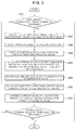
- FIG. 3 is a diagram showing an example of a process of correcting a fuel injection amount according to an exemplary embodiment of the present invention
- FIG. 4 is a diagram showing an example of pressure which is detected through a fuel sensor of the present invention.
- FIG. 5 is a diagram showing an example of a frequency analysis values for each target fuel amount of an input signal which is detected in FIG. 4 .
- FIG. 1 is a diagram showing the configuration of a system for correcting a fuel injection amount according to an exemplary embodiment of the present invention, in which a high-pressure pump 7 that increases the pressure of fuel which is supplied from a fuel tank 9 to high pressure is provided and a fuel pressure rail 3 is provided to store and distribute super high-pressure fuel increased in pressure by the high-pressure pump 7 to individual injectors 1 .
- Injectors 1 a , 1 b , 1 c , and 1 d are provided for cylinders, respectively, to receive and supply fuel from the fuel pressure rail 3 .
- Driving conditions reflecting the traveling state of a vehicle are input to a controller CLR to adjust the fuel amount which is injected through the injectors 1 and a target fuel amount is determined on the basis of the input driving conditions by the controller CLR.
- a pressure sensor 5 for measuring pressure in the fuel pressure rail 3 is mounted on the fuel pressure rail 3 and a detecting value of the fuel pressure rail 3 detected by the pressure sensor 5 is transmitted to the controller CLR, whereby pressure may be detected.
- the controller CLR may be an ECU.
- the controller CLR according to exemplary embodiments of the present invention may be implemented through a nonvolatile memory configured to store algorithms for controlling operation of various components of a vehicle or data about software commands for executing the algorithms, and a processor configured to perform operation to be described below using the data stored in the memory.
- the memory and the processor may be individual chips. Alternatively, the memory and the processor may be integrated in a single chip.
- the processor may be implemented as one or more processors.
- the controller CLR having the present configuration includes a fuel injection controller 10 , a pressure signal analyzer 20 , a fuel difference calculator 30 , and a fuel information corrector 40 .
- the fuel injection controller 10 applies a current value for injecting a target fuel amount to an injector 1 such that fuel is injected when it is determined that a fuel amount correction driving condition that does not requires fuel injection is satisfied.
- the current value which is applied to the injector 1 is a current value previously learned through correction and fuel may be injected in accordance with the applied current value.
- the controller CLR may further include a data storage 50 and current values that will be applied to the injector 1 for each of target fuel amounts may be stored in the data storage 50 .
- the target fuel amount is a fuel amount to be learned and several target fuel amounts may be set within a fuel injection amount which is used for pilot injection and may be stored in the data storage 50 .
- the learning order of the stored target fuel amount may be freely determined or the learning order of target fuel amounts stored in accordance with the traveling states of a vehicle may be determined.
- the pressure signal analyzer 20 detects a pressure signal from the fuel pressure rail 3 from which fuel is injected, through the pressure sensor 5 and determines a frequency analysis value of the detected pressure signal when fuel according to a target fuel amount is injected.
- the frequency analysis value of the pressure signal may be determined using a FFT algorithm.
- the fuel difference calculator 30 determines a fuel amount difference corresponding to the difference between the frequency analysis value for the target fuel amount determined by the pressure signal analyzer 20 and a reference frequency analysis value stored in advance.
- Reference frequency analysis values for pressure signals detected from the fuel pressure rail 3 when fuel is injected are stored in advance in the data storage 50 respectively for target fuel amounts through tests. Accordingly, it is possible to compare the frequency analysis value determined for the pressure signal and a reference frequency analysis value with each other.
- the fuel injection corrector 40 corrects a current value of the injector 1 which is applied to inject the target fuel amount to remove the fuel amount difference determined by the fuel difference calculator 30 .
- the fuel injection corrector 40 corrects and learns a corresponding current value by reflecting the correction current value to the current value of a corresponding target fuel amount stored in the data storage 50 . Accordingly, when a target fuel amount is injected through a corresponding injector 1 , the operation of the injector 1 is controlled with the current value learned through correction and the fuel is injected.
- the difference between the target fuel amount and the amount of the actually injected fuel is removed and fuel is injected to be more suitable for driving conditions of the vehicle, whereby the temperature of a catalyst is more accurately controlled. Accordingly, it is possible to improve EM and prevent hardware damage to the catalyst.
- a method of correcting a fuel injection amount includes a fuel injection control step, a pressure signal detection step, a frequency analysis step, a fuel amount difference determination step, and a fuel injection correction step.
- the controller CLR applies a current value for injecting a target fuel amount to an injector 1 to inject fuel under a driving condition that does not requires fuel injection.
- a current value for injecting a target fuel amount is applied to one of several injectors 1 , whereby fuel is injected through the corresponding injector 1 .
- the driving condition that does not requires fuel injection may be overrun in which fuel which is supplied to an injector valve when an engine brake is used or deceleration is performed is fully closed, and may be other driving conditions in which fuel injection is blocked.
- the controller CLR detects a pressure signal from the fuel pressure rail 3 from which fuel is injected, as shown in FIG. 4 .
- the pressure signal may be a signal which is detected by the pressure sensor 5 mounted on the high-pressure fuel pressure rail 3 (e.g., a common rail).
- the controller CLR determines a frequency analysis value of the detected pressure signal.
- FIG. 5 is a graph showing frequency analysis values respectively for target fuel amount.
- FFT Fast Fourier Transform
- the controller CLR determines a fuel amount difference corresponding to the difference value between the determined frequency analysis value and a reference frequency analysis value stored in advance.
- the controller CLR corrects a current value of an injector 1 which is applied to inject the target fuel amount to remove the fuel amount difference.
- a maximum frequency analysis value is determined from a target fuel amount through analysis using the FFT algorithm.
- the difference value between the determined maximum frequency analysis value and a maximum reference frequency analysis value stored for the target fuel amount in the data storage 50 is determined.
- a maximum frequency analysis value which is the peak value of the determined frequency analysis value and a maximum reference frequency analysis value which is the peak value of a stored frequency analysis value are compared.
- the reason of comparing maximum values, as described above, is for increasing reliability of corresponding target fuel amount because the peak values of analysis values determined through frequency analysis for target fuel amounts have large differences and the other analyzed values for the target fuel amounts have little differences.
- a fuel amount difference corresponding to the difference between the determined maximum frequency analysis value and the stored maximum reference frequency analysis value and a current value corresponding to the fuel amount difference is determined, whereby a current value of the injector 1 which is applied to inject the target fuel amount is corrected.
- Such correction of a current value for the injector may be sequentially performed for all the injectors 1 . That is, when an engine has four injectors 1 a , 1 b , 1 c , and 1 d , current value correction may be performed for all of the four injectors 1 a , 1 b , 1 c , and 1 d.
- current value correction of the injectors 1 may be performed for each of target fuel amount by differently setting the target fuel amounts to be learned.
- the target fuel amount may be set in the unit of 1 mg/str and a current value of the injector 1 may be corrected for each target fuel amount.
- a current value of an injector 1 for a target fuel amount of the injector 1 to be learned is applied and fuel is injected (S 20 ). That is, a current value of the injector 1 for injecting a target fuel amount to be learned is applied to the injector 1 , whereby fuel is injected by the target fuel amount.
- a pressure signal is detected through the pressure sensor 5 mounted on the fuel pressure rail 3 (S 30 ) and a maximum frequency analysis value for the target fuel amount is determined by analyzing the detected pressure signal through an FFT algorithm (S 40 ).
- the maximum frequency analysis value for the currently injected target fuel amount and a maximum reference frequency analysis value stored for the target fuel amount in the data storage 50 are compared, determining the difference value of the analysis values (S 50 ).
- a fuel amount difference corresponding to the difference value is determined (S 60 )
- a correction current value of the injector 1 corresponding to the fuel amount difference is determined (S 70 )
- the present correction process may be performed on the injector 1 for each of target fuel amounts to be learned. Furthermore, the present correction process is performed on injector other than the injector 1 for each of target fuel amounts to be learned, being able to correct the fuel injection amounts of the injectors 1 .
- the difference between a target fuel amount and the amount of the actually injected fuel is removed and fuel is injected to be more suitable for driving conditions of the vehicle, whereby the temperature of a catalyst is more accurately controlled. Accordingly, it is possible to improve EM and prevent hardware damage to the catalyst.
Landscapes
- Engineering & Computer Science (AREA)
- Chemical & Material Sciences (AREA)
- Combustion & Propulsion (AREA)
- Mechanical Engineering (AREA)
- General Engineering & Computer Science (AREA)
- Electrical Control Of Air Or Fuel Supplied To Internal-Combustion Engine (AREA)
- Combined Controls Of Internal Combustion Engines (AREA)
Abstract
Description
Claims (13)
Applications Claiming Priority (2)
| Application Number | Priority Date | Filing Date | Title |
|---|---|---|---|
| KR1020190071970A KR20200144246A (en) | 2019-06-18 | 2019-06-18 | Method and system for compensating fuel injection amount |
| KR10-2019-0071970 | 2019-06-18 |
Publications (2)
| Publication Number | Publication Date |
|---|---|
| US20200400092A1 US20200400092A1 (en) | 2020-12-24 |
| US11041454B2 true US11041454B2 (en) | 2021-06-22 |
Family
ID=73654523
Family Applications (1)
| Application Number | Title | Priority Date | Filing Date |
|---|---|---|---|
| US16/678,578 Expired - Fee Related US11041454B2 (en) | 2019-06-18 | 2019-11-08 | Method and system for correcting fuel injection amount |
Country Status (4)
| Country | Link |
|---|---|
| US (1) | US11041454B2 (en) |
| KR (1) | KR20200144246A (en) |
| CN (1) | CN112096533A (en) |
| DE (1) | DE102019218287A1 (en) |
Families Citing this family (2)
| Publication number | Priority date | Publication date | Assignee | Title |
|---|---|---|---|---|
| CN116480481B (en) * | 2023-05-15 | 2025-07-18 | 一汽解放汽车有限公司 | Fuel injector control method and device, fuel injection system and vehicle |
| CN118375527B (en) * | 2024-05-31 | 2026-03-13 | 东风商用车有限公司 | Methods, devices, electronic equipment and storage media for estimating fuel injection quantity |
Citations (9)
| Publication number | Priority date | Publication date | Assignee | Title |
|---|---|---|---|---|
| US6901791B1 (en) * | 1999-10-19 | 2005-06-07 | Robert Bosch Gmbh | Method and device for diagnosing of a fuel supply system |
| KR100534724B1 (en) | 2002-10-23 | 2005-12-07 | 현대자동차주식회사 | Cylinder injection controling method of common rail system in diesel engine |
| US20060156801A1 (en) * | 2002-10-25 | 2006-07-20 | Ulrich Kuhn | Method and device for measuring the injection rate of an injection valve for liquids |
| US7299706B2 (en) * | 2005-02-04 | 2007-11-27 | Michigan Custom Machines, Inc. | Flow meter and method of using the same |
| US7516652B2 (en) * | 2004-12-01 | 2009-04-14 | Robert Bosch Gmbh | Method and device for exciting pressure fluctuations in a fuel supply system of an internal combustion engine |
| US20090205413A1 (en) * | 2008-02-15 | 2009-08-20 | Hitachi, Ltd. | Diagnostic apparatus for high-pressure fuel supply system |
| US20130275026A1 (en) * | 2012-04-13 | 2013-10-17 | Caterpillar Inc. | Common Rail System Fault Diagnostic Using Digital Resonating Filter |
| US20150233318A1 (en) * | 2014-02-19 | 2015-08-20 | GM Global Technology Operations LLC | Method of operating an internal combustion engine |
| US20180142644A1 (en) * | 2016-11-23 | 2018-05-24 | GM Global Technology Operations LLC | Controlling fuel injectors using correlated gain curve data |
Family Cites Families (13)
| Publication number | Priority date | Publication date | Assignee | Title |
|---|---|---|---|---|
| JP3966096B2 (en) * | 2002-06-20 | 2007-08-29 | 株式会社デンソー | Injection amount control device for internal combustion engine |
| EP1870586B1 (en) * | 2006-06-16 | 2018-12-05 | Delphi International Operations Luxembourg S.à r.l. | Apparatus for detecting and identifying component failure in a fuel system |
| GB0613948D0 (en) * | 2006-07-13 | 2006-08-23 | Delphi Tech Inc | Fuel temperature estimation and control of fuel injection |
| DE102008040227A1 (en) * | 2008-07-07 | 2010-01-14 | Robert Bosch Gmbh | Method and apparatus for pressure wave compensation in successive injections in an injection system of an internal combustion engine |
| KR100992665B1 (en) * | 2008-11-24 | 2010-11-05 | 현대자동차주식회사 | Fuel level correction method according to injector aging |
| GB2495755A (en) * | 2011-10-20 | 2013-04-24 | Gm Global Tech Operations Inc | Correction of fuel injection timings in an internal combustion engine |
| US9255543B2 (en) * | 2012-12-14 | 2016-02-09 | Hyundai Motor Company | Fuel injection amount compensating method |
| KR101755864B1 (en) * | 2015-10-21 | 2017-07-10 | 현대자동차주식회사 | Controlling method of engine rpm |
| ITUB20159189A1 (en) * | 2015-12-16 | 2017-06-16 | Torino Politecnico | APPARATUS AND METHOD FOR THE CONTROL OF THE QUANTITY OF FUEL INJECTED IN AN INTERNAL COMBUSTION ENGINE |
| ITUB20160530A1 (en) * | 2016-01-27 | 2017-07-27 | Torino Politecnico | SYSTEM OF INJECTION, APPARATUS AND METHOD FOR THE CONTROL OF THE INJECTED FUEL QUANTITY |
| JP2017141739A (en) * | 2016-02-10 | 2017-08-17 | トヨタ自動車株式会社 | Control device for internal combustion engine |
| DE102017217113A1 (en) * | 2017-09-26 | 2019-03-28 | Robert Bosch Gmbh | Method for operating an internal combustion engine and electronic control unit for an internal combustion engine |
| GB2569579A (en) * | 2017-12-20 | 2019-06-26 | Delphi Tech Ip Ltd | Method of determining rail pressure in a common rail fuel system |
-
2019
- 2019-06-18 KR KR1020190071970A patent/KR20200144246A/en not_active Ceased
- 2019-11-08 US US16/678,578 patent/US11041454B2/en not_active Expired - Fee Related
- 2019-11-26 CN CN201911172565.7A patent/CN112096533A/en active Pending
- 2019-11-26 DE DE102019218287.9A patent/DE102019218287A1/en not_active Withdrawn
Patent Citations (10)
| Publication number | Priority date | Publication date | Assignee | Title |
|---|---|---|---|---|
| US6901791B1 (en) * | 1999-10-19 | 2005-06-07 | Robert Bosch Gmbh | Method and device for diagnosing of a fuel supply system |
| KR100534724B1 (en) | 2002-10-23 | 2005-12-07 | 현대자동차주식회사 | Cylinder injection controling method of common rail system in diesel engine |
| US20060156801A1 (en) * | 2002-10-25 | 2006-07-20 | Ulrich Kuhn | Method and device for measuring the injection rate of an injection valve for liquids |
| US7516652B2 (en) * | 2004-12-01 | 2009-04-14 | Robert Bosch Gmbh | Method and device for exciting pressure fluctuations in a fuel supply system of an internal combustion engine |
| US7299706B2 (en) * | 2005-02-04 | 2007-11-27 | Michigan Custom Machines, Inc. | Flow meter and method of using the same |
| US20090205413A1 (en) * | 2008-02-15 | 2009-08-20 | Hitachi, Ltd. | Diagnostic apparatus for high-pressure fuel supply system |
| US20130275026A1 (en) * | 2012-04-13 | 2013-10-17 | Caterpillar Inc. | Common Rail System Fault Diagnostic Using Digital Resonating Filter |
| US20150233318A1 (en) * | 2014-02-19 | 2015-08-20 | GM Global Technology Operations LLC | Method of operating an internal combustion engine |
| US9765725B2 (en) * | 2014-02-19 | 2017-09-19 | GM Global Technology Operations LLC | Method of operating an internal combustion engine |
| US20180142644A1 (en) * | 2016-11-23 | 2018-05-24 | GM Global Technology Operations LLC | Controlling fuel injectors using correlated gain curve data |
Also Published As
| Publication number | Publication date |
|---|---|
| US20200400092A1 (en) | 2020-12-24 |
| CN112096533A (en) | 2020-12-18 |
| KR20200144246A (en) | 2020-12-29 |
| DE102019218287A1 (en) | 2020-12-24 |
Similar Documents
| Publication | Publication Date | Title |
|---|---|---|
| US7703437B2 (en) | Electronic control device for controlling the internal combustion engine in a motor vehicle | |
| US7926331B2 (en) | Detection of fuel property based on change in rotational speed of engine | |
| US7836870B2 (en) | Method for controlling an internal combustion engine of a motor vehicle | |
| US7909020B2 (en) | Controller for internal combustion engine | |
| US11041454B2 (en) | Method and system for correcting fuel injection amount | |
| US9976506B2 (en) | Method and device for calibrating post-injections of an internal combustion engine | |
| US9109561B2 (en) | Method and device for zero-fuel quantity calibration of a fuel injector | |
| US6985807B2 (en) | Injection quantity controller for an internal combustion engine | |
| JP2003314337A (en) | Accumulator type fuel injection device | |
| US20140048047A1 (en) | Fuel supply control device and control method for engine | |
| US20100139614A1 (en) | Method of pilot injection control and system thereof | |
| JP2011252418A (en) | Fuel injection system for internal combustion engine | |
| US12516644B2 (en) | Pressure drop analysis strategy | |
| US20170342930A1 (en) | Diagnostic device | |
| US6932059B2 (en) | Fuel injection system of internal combustion engine | |
| US11346300B2 (en) | Method and device for learning opening time of injector for vehicle engine | |
| JP4551425B2 (en) | Fuel injection control device for diesel engine | |
| US7305872B2 (en) | Method for operating an internal combustion engine | |
| US10570830B2 (en) | Method and system for controlling injection of mixture fuel in an internal combustion engine | |
| JP7021595B2 (en) | Fuel passage characteristic acquisition device | |
| KR102473710B1 (en) | Method and apparatus for fuel amount training and compensation in GDI engine | |
| US20180245535A1 (en) | Method for ascertaining a cause of a fault in an injection system of an internal combustion engine | |
| US10844806B2 (en) | Method and apparatus for detecting drift of pilot | |
| JP2009008057A (en) | Fuel injection device for internal combustion engine of vehicle | |
| KR20210076501A (en) | Method for compensating static flow of an injector and control apparatus for fuel injection of an injector |
Legal Events
| Date | Code | Title | Description |
|---|---|---|---|
| AS | Assignment |
Owner name: KIA MOTORS CORPORATION, KOREA, REPUBLIC OF Free format text: ASSIGNMENT OF ASSIGNORS INTEREST;ASSIGNOR:OH, JEONG SANG;REEL/FRAME:050960/0448 Effective date: 20191104 Owner name: HYUNDAI MOTOR COMPANY, KOREA, REPUBLIC OF Free format text: ASSIGNMENT OF ASSIGNORS INTEREST;ASSIGNOR:OH, JEONG SANG;REEL/FRAME:050960/0448 Effective date: 20191104 |
|
| FEPP | Fee payment procedure |
Free format text: ENTITY STATUS SET TO UNDISCOUNTED (ORIGINAL EVENT CODE: BIG.); ENTITY STATUS OF PATENT OWNER: LARGE ENTITY |
|
| STPP | Information on status: patent application and granting procedure in general |
Free format text: NOTICE OF ALLOWANCE MAILED -- APPLICATION RECEIVED IN OFFICE OF PUBLICATIONS |
|
| STPP | Information on status: patent application and granting procedure in general |
Free format text: PUBLICATIONS -- ISSUE FEE PAYMENT RECEIVED |
|
| STPP | Information on status: patent application and granting procedure in general |
Free format text: PUBLICATIONS -- ISSUE FEE PAYMENT VERIFIED |
|
| STCF | Information on status: patent grant |
Free format text: PATENTED CASE |
|
| FEPP | Fee payment procedure |
Free format text: MAINTENANCE FEE REMINDER MAILED (ORIGINAL EVENT CODE: REM.); ENTITY STATUS OF PATENT OWNER: LARGE ENTITY |
|
| LAPS | Lapse for failure to pay maintenance fees |
Free format text: PATENT EXPIRED FOR FAILURE TO PAY MAINTENANCE FEES (ORIGINAL EVENT CODE: EXP.); ENTITY STATUS OF PATENT OWNER: LARGE ENTITY |
|
| STCH | Information on status: patent discontinuation |
Free format text: PATENT EXPIRED DUE TO NONPAYMENT OF MAINTENANCE FEES UNDER 37 CFR 1.362 |
|
| FP | Lapsed due to failure to pay maintenance fee |
Effective date: 20250622 |