US11039880B2 - Method of surgical perforation via the delivery of energy - Google Patents
Method of surgical perforation via the delivery of energy Download PDFInfo
- Publication number
- US11039880B2 US11039880B2 US15/463,913 US201715463913A US11039880B2 US 11039880 B2 US11039880 B2 US 11039880B2 US 201715463913 A US201715463913 A US 201715463913A US 11039880 B2 US11039880 B2 US 11039880B2
- Authority
- US
- United States
- Prior art keywords
- dilator
- perforation
- tissue
- sheath
- distal end
- Prior art date
- Legal status (The legal status is an assumption and is not a legal conclusion. Google has not performed a legal analysis and makes no representation as to the accuracy of the status listed.)
- Expired - Lifetime, expires
Links
Images


Classifications
-
- A—HUMAN NECESSITIES
- A61—MEDICAL OR VETERINARY SCIENCE; HYGIENE
- A61B—DIAGNOSIS; SURGERY; IDENTIFICATION
- A61B18/00—Surgical instruments, devices or methods for transferring non-mechanical forms of energy to or from the body
- A61B18/04—Surgical instruments, devices or methods for transferring non-mechanical forms of energy to or from the body by heating
- A61B18/12—Surgical instruments, devices or methods for transferring non-mechanical forms of energy to or from the body by heating by passing a current through the tissue to be heated, e.g. high-frequency current
- A61B18/14—Probes or electrodes therefor
- A61B18/1492—Probes or electrodes therefor having a flexible, catheter-like structure, e.g. for heart ablation
-
- A—HUMAN NECESSITIES
- A61—MEDICAL OR VETERINARY SCIENCE; HYGIENE
- A61B—DIAGNOSIS; SURGERY; IDENTIFICATION
- A61B18/00—Surgical instruments, devices or methods for transferring non-mechanical forms of energy to or from the body
- A61B18/04—Surgical instruments, devices or methods for transferring non-mechanical forms of energy to or from the body by heating
- A61B18/12—Surgical instruments, devices or methods for transferring non-mechanical forms of energy to or from the body by heating by passing a current through the tissue to be heated, e.g. high-frequency current
- A61B18/14—Probes or electrodes therefor
- A61B18/16—Indifferent or passive electrodes for grounding
-
- A—HUMAN NECESSITIES
- A61—MEDICAL OR VETERINARY SCIENCE; HYGIENE
- A61M—DEVICES FOR INTRODUCING MEDIA INTO, OR ONTO, THE BODY; DEVICES FOR TRANSDUCING BODY MEDIA OR FOR TAKING MEDIA FROM THE BODY; DEVICES FOR PRODUCING OR ENDING SLEEP OR STUPOR
- A61M29/00—Dilators with or without means for introducing media, e.g. remedies
- A61M29/02—Dilators made of swellable material
-
- A—HUMAN NECESSITIES
- A61—MEDICAL OR VETERINARY SCIENCE; HYGIENE
- A61M—DEVICES FOR INTRODUCING MEDIA INTO, OR ONTO, THE BODY; DEVICES FOR TRANSDUCING BODY MEDIA OR FOR TAKING MEDIA FROM THE BODY; DEVICES FOR PRODUCING OR ENDING SLEEP OR STUPOR
- A61M5/00—Devices for bringing media into the body in a subcutaneous, intra-vascular or intramuscular way; Accessories therefor, e.g. filling or cleaning devices, arm-rests
- A61M5/007—Devices for bringing media into the body in a subcutaneous, intra-vascular or intramuscular way; Accessories therefor, e.g. filling or cleaning devices, arm-rests for contrast media
-
- A—HUMAN NECESSITIES
- A61—MEDICAL OR VETERINARY SCIENCE; HYGIENE
- A61B—DIAGNOSIS; SURGERY; IDENTIFICATION
- A61B18/00—Surgical instruments, devices or methods for transferring non-mechanical forms of energy to or from the body
- A61B18/04—Surgical instruments, devices or methods for transferring non-mechanical forms of energy to or from the body by heating
- A61B18/12—Surgical instruments, devices or methods for transferring non-mechanical forms of energy to or from the body by heating by passing a current through the tissue to be heated, e.g. high-frequency current
- A61B18/1206—Generators therefor
-
- A—HUMAN NECESSITIES
- A61—MEDICAL OR VETERINARY SCIENCE; HYGIENE
- A61B—DIAGNOSIS; SURGERY; IDENTIFICATION
- A61B18/00—Surgical instruments, devices or methods for transferring non-mechanical forms of energy to or from the body
- A61B18/18—Surgical instruments, devices or methods for transferring non-mechanical forms of energy to or from the body by applying electromagnetic radiation, e.g. microwaves
- A61B18/20—Surgical instruments, devices or methods for transferring non-mechanical forms of energy to or from the body by applying electromagnetic radiation, e.g. microwaves using laser
- A61B18/22—Surgical instruments, devices or methods for transferring non-mechanical forms of energy to or from the body by applying electromagnetic radiation, e.g. microwaves using laser the beam being directed along or through a flexible conduit, e.g. an optical fibre; Couplings or hand-pieces therefor
- A61B18/24—Surgical instruments, devices or methods for transferring non-mechanical forms of energy to or from the body by applying electromagnetic radiation, e.g. microwaves using laser the beam being directed along or through a flexible conduit, e.g. an optical fibre; Couplings or hand-pieces therefor with a catheter
-
- A—HUMAN NECESSITIES
- A61—MEDICAL OR VETERINARY SCIENCE; HYGIENE
- A61B—DIAGNOSIS; SURGERY; IDENTIFICATION
- A61B18/00—Surgical instruments, devices or methods for transferring non-mechanical forms of energy to or from the body
- A61B2018/00315—Surgical instruments, devices or methods for transferring non-mechanical forms of energy to or from the body for treatment of particular body parts
- A61B2018/00345—Vascular system
- A61B2018/00351—Heart
- A61B2018/0038—Foramen ovale
-
- A—HUMAN NECESSITIES
- A61—MEDICAL OR VETERINARY SCIENCE; HYGIENE
- A61B—DIAGNOSIS; SURGERY; IDENTIFICATION
- A61B18/00—Surgical instruments, devices or methods for transferring non-mechanical forms of energy to or from the body
- A61B2018/00571—Surgical instruments, devices or methods for transferring non-mechanical forms of energy to or from the body for achieving a particular surgical effect
- A61B2018/00601—Cutting
-
- A—HUMAN NECESSITIES
- A61—MEDICAL OR VETERINARY SCIENCE; HYGIENE
- A61B—DIAGNOSIS; SURGERY; IDENTIFICATION
- A61B18/00—Surgical instruments, devices or methods for transferring non-mechanical forms of energy to or from the body
- A61B2018/00636—Sensing and controlling the application of energy
- A61B2018/00773—Sensed parameters
- A61B2018/00839—Bioelectrical parameters, e.g. ECG, EEG
-
- A—HUMAN NECESSITIES
- A61—MEDICAL OR VETERINARY SCIENCE; HYGIENE
- A61B—DIAGNOSIS; SURGERY; IDENTIFICATION
- A61B90/00—Instruments, implements or accessories specially adapted for surgery or diagnosis and not covered by any of the groups A61B1/00 - A61B50/00, e.g. for luxation treatment or for protecting wound edges
- A61B90/06—Measuring instruments not otherwise provided for
- A61B2090/064—Measuring instruments not otherwise provided for for measuring force, pressure or mechanical tension
-
- A—HUMAN NECESSITIES
- A61—MEDICAL OR VETERINARY SCIENCE; HYGIENE
- A61B—DIAGNOSIS; SURGERY; IDENTIFICATION
- A61B90/00—Instruments, implements or accessories specially adapted for surgery or diagnosis and not covered by any of the groups A61B1/00 - A61B50/00, e.g. for luxation treatment or for protecting wound edges
- A61B90/39—Markers, e.g. radio-opaque or breast lesions markers
- A61B2090/3966—Radiopaque markers visible in an X-ray image
Definitions
- This disclosure relates to a method, and device therefore, for creating a surgical perforation via energy delivery. More particularly, this disclosure relates to a method for creating a surgical perforation using an electrosurgical apparatus and at least two dilators.
- Trans-septal catherization procedures typically involve insertion of a needle, such as the trans-septal needle of Cook Incorporated (Bloomington, Ind., USA) into a patient's heart.
- the needle comprises a stiff metal cannula with a sharpened distal tip.
- the needle is generally introduced through a dilator and guiding sheath set in the femoral vein and advanced through the vasculature into the right atrium. From there the needle tip is positioned at the fossa ovalis, the preferred location on the septum for creating a puncture.
- Joseph states that trans-jugular septal puncture may find application in cardiac electrophysiology because it offers a more direct approach to the mitral annulus, left ventricle, and inferior aspect of the left atrium.
- the author states that in transvenous mitral valvuloplasty, the jugular approach simplifies septal puncture and mitral valve crossing in patients with a huge left atrium and distorted anatomy, besides making the procedure feasible in the presence of obstruction of the inferior vena cava.
- needle trans-septal punctures from the jugular approach are more difficult to perform and require significant practice.
- the SafeSheath® CSG Worley described in the publication entitled “Using the Pressure Products SafeSheath CSG Worley with Radio Opaque Soft-Tipped Braided Core” is a surgical sheath designed to be introduced into a patient's heart through the Superior Vena Cava (SVC) and on through the coronary sinus.
- SVC Superior Vena Cava
- the SafeSheath® device is not intended or structured to allow for perforation of patient material nor is it structured to allow for positioning within a patient's heart for perforation and/or dilation.
- U.S. Pat. No. 7,056,294 to Khairkhahan et al discloses a method that uses mechanical force to gain transseptal access.
- the method includes positioning a needle against material and mechanically advancing the needle to gain transseptal access.
- the tip of a sheath-dilator-transseptal needle combination is placed in the desired location against the fossa ovalis and the transseptal needle is abruptly advanced to accomplish a quick puncture.
- the needle preferably comprises a tubular structure such as a stainless steel hypotube having a sharpened distal end.
- Some embodiments include additional mechanical advancement means such as cutting edges or a corkscrew thread.
- the disclosed method does not include using RF energy to perforate the septum and gain transseptal access.
- U.S. Pat. No. 6,814,733 to Schwartz et al includes a method of ablation to create circumferential lesions in the myocardial sleeve of the pulmonary vein to block electrical propagation between the pulmonary vein and the left atrium.
- Schwartz teaches conventional mechanical needle perforation of the interatrial septum.
- the method includes a needle and guide-wire crossing the septum before an energy delivery coil.
- the coil can be energized for ablation of septal tissue to ease the passage of a catheter through the septum.
- This method can include using energy to enlarge an already existing perforation in a septum, but it does not include using energy to perforate a septum.
- the method's preferred approach to the heart is from an inferior direction.
- the safe perforation of heart tissue of a patient when an inferior approach to the heart is contraindicated can be accomplished by introducing an apparatus using a superior approach, positioning the apparatus at the correct tissue location and delivering a controlled amount of non-mechanical energy to the tissue.
- One such method comprises the steps of (a) from a superior approach, advancing a first dilator (having a shape for facilitating positioning its distal end against tissue) until the first dilator's distal end is adjacent the tissue, (b) using an electrosurgical apparatus positioned through the first dilator to create a perforation by delivering energy to the tissue, and advancing the distal end of the electrosurgical apparatus through the perforation, and (c) withdrawing the first dilator and advancing over the electrosurgical apparatus a second dilator being configured for facilitating advancement of the second dilator through the perforation wherein the outer diameter of the second dilator is equal to or less than that of the first dilator.
- embodiments of the present invention are for a method of perforating a tissue of a heart of a patient, the method utilizing an electrosurgical apparatus and a delivery system comprising at least two dilators wherein a first dilator is configured for facilitating positioning of the electrosurgical apparatus adjacent the tissue and wherein a second dilator is configured for advancement through a perforation in the tissue.
- This method comprises the steps of: (a) advancing the first dilator into the heart of the patient, from a superior approach, until a distal end of the first dilator is adjacent the tissue; (b) using the electrosurgical apparatus, being positioned through the first dilator, to create a perforation in the tissue by delivering electrical energy to the tissue; (c) advancing the distal end of the electrosurgical apparatus through the perforation; (d) withdrawing the first dilator; and (e) advancing the second dilator over the electrosurgical apparatus, wherein an outer diameter of the second dilator is substantially equal to or less than an outer diameter of the first dilator.
- the tissue is an atrial septum.
- Typical embodiments include the electrosurgical apparatus comprising an energy delivery device at a distal end thereof, and step (b) including, prior to delivering energy, positioning the energy delivery device adjacent the tissue, wherein such embodiments typically further include step (b) comprising energy being delivered through the energy delivery device to the tissue.
- step (e) further comprises advancing the second dilator through the perforation to thereby dilate the perforation.
- a taper at a distal tip of the second dilator has a more gradual slope than a taper at a distal tip of the first dilator.
- the taper at the distal tip of the first dilator has a length of about 0.5 cm to about 1 cm.
- Some embodiments comprise the taper at the distal tip of the second dilator having a length of about 2 to about 5 cm.
- Some embodiments of the first broad aspect include the delivery system further comprising a sheath, and the outer diameter of the first dilator and the outer diameter of the second dilator being substantially equal and corresponding with an inner diameter of the sheath.
- step (a) further includes positioning the first dilator such that a distal end of the first dilator is oriented at an angle of about 80 degrees to about 100 degrees relative to a surface of the atrial septum.
- the distal end of the first dilator is oriented substantially perpendicularly relative to the surface of the atrial septum.
- step (e) further comprises positioning the second dilator such that a distal end of the second dilator is oriented at an angle of less than 90 degrees relative to the surface of the atrial septum.
- first feature typically comprise the electrosurgical apparatus being bent at an angle greater than 90 degrees when it is being positioned.
- first dilator has a distal tip with a curve greater than 90 degrees to facilitate positioning the distal end of the first dilator and the second dilator has a distal tip with a curve of less than 90 degrees to facilitate transmitting mechanical force applied at a proximal end of the second dilator to thereby advance the second dilator through the perforation.
- the tissue is an atrial septum of the heart and step (a) further comprises positioning the first dilator such that a distal end of the first dilator is oriented at an oblique angle relative to a surface of the atrial septum.
- the first dilator has a flexural rigidity of about 3 Ncm 2 to about 7 Ncm 2 and the second dilator has a flexural rigidity of about 23 Ncm 2 to about 28 Ncm 2 .
- step (a) further comprises positioning the first dilator such that a distal end of the first dilator is oriented at an angle of about 20 degrees to about 70 degrees relative to a surface of the atrial septum. In some such embodiments, the distal end of the first dilator is oriented at an angle of about 45 degrees relative to a surface of the atrial septum. In some embodiments of the second feature, step (c) further includes positioning the second dilator such that a distal end of the second dilator is oriented at an angle of about 20 degrees to about 70 degrees relative to a surface of the atrial septum.
- Some embodiments of the second feature include the delivery system further comprising a sheath and step (a) further comprises using the sheath for positioning the first dilator, wherein the sheath and the first dilator are supported by a superior vena cava; and step (e) further includes using the sheath for positioning the second dilator, wherein the sheath and the second dilator are supported by the superior vena cava.
- FIG. 1 illustrates a schematic view of an electrosurgical system including an electrosurgical device in accordance with an embodiment of the invention
- FIG. 2 illustrates a side cross-sectional view of the device of FIG. 1 ;
- FIG. 3 illustrates a cross-sectional view of an alternate embodiment of the device
- FIG. 4 illustrates an active electrode of the device of FIG. 1 ;
- FIG. 5 illustrates the distal region of a device in accordance with an alternate embodiment of the invention
- FIG. 6 illustrates a side cross-sectional view of an alternate embodiment of the device
- FIG. 7 illustrates a side cross-sectional view of an alternate embodiment of the device
- FIGS. 8A and 8B illustrate two possible embodiments of a guiding sheath
- FIG. 9 illustrates one embodiment of a dilator
- FIGS. 10A, 10B and 10C illustrate alternate embodiments of a dilator
- FIG. 11 illustrates a first position of one embodiment of the present invention within a patient's heart
- FIG. 12 illustrates a second position of one embodiment of the present invention within a patient's heart
- FIGS. 13A and 13B illustrate first positions of alternate embodiments of the present invention within a patient's heart
- FIGS. 14A and 14B illustrate second positions of alternate embodiments of the present invention within a patient's heart
- FIG. 15 illustrates a position of one embodiment of a guiding sheath of the present invention within a patient's heart
- FIGS. 16A and 16B illustrate a flow chart of a trans-septal perforation method in accordance with an embodiment of this invention.
- FIGS. 17A and 17B illustrate another embodiment of the present invention.
- the perforation or puncture of a patient's heart tissue when an inferior approach to the heart is contraindicated can be accomplished by introducing an electrosurgical apparatus using a superior approach, that is, an approach from above a patient's heart.
- the apparatus can then be positioned and a controlled amount of non-mechanical energy can then be delivered to tissue to create the perforation or puncture.
- One embodiment is a method including the steps of (a) from a superior approach, advancing a first dilator (having a shape for facilitating positioning its distal end against tissue) until the first dilator's distal end is adjacent the tissue, (b) using an electrosurgical apparatus positioned through the first dilator to create a perforation by delivering energy to the tissue, and advancing the distal end of the electrosurgical apparatus through the perforation, and (c) withdrawing the first dilator, and advancing over the electrosurgical apparatus a second dilator configured for facilitating advancement of the second dilator through the perforation, wherein the outer diameter of the second dilator is equal to or less than that of the first dilator.
- a relevant definition of mechanical energy is “a combination of kinetic and potential energy resulting from the movement or release of a machine component, such as a wheel or spring”.
- the definition is not intended to include thermal or electrical energy.
- Benson et. al. discusses the fundamental differences between RF ablation and RF perforation.
- energy is applied to rapidly increase tissue temperature to the extent that the intracellular fluid becomes converted to steam, inducing cell lysis as a result of elevated pressure within the cell.
- cell lysis Upon the occurrence of cell lysis and rupture, a void is created, allowing the tip of the catheter to penetrate the tissue.
- RF perforation devices must apply a high voltage to the tissue region over a short period of time. Also, the tip of the device being used should be relatively small, in order to increase the impedance of the device.
- perforation is defined as the creation of a void within a material.
- FIG. 1 illustrates an embodiment of an apparatus 102 in a system 100 .
- Apparatus 102 comprises an elongate member 104 having a distal region 106 , and a proximal region 108 .
- Distal region 106 is adapted to be inserted within and along a lumen of a body of a patient, such as a patient's vasculature, and maneuverable therethrough to a desired location proximate material, such as tissue, to be perforated.
- the elongate member 104 may be tubular in configuration, having at least one lumen extending from proximal region 108 to distal region 106 such as lumen 200 shown in FIG. 2 .
- Elongate member 104 may be constructed of a biocompatible polymer material that provides column strength to apparatus 102 .
- the elongate member 104 is sufficiently stiff to permit a dilator 910 and a guiding sheath 800 (See FIG. 8 ) to be easily advanced over apparatus 102 and through a perforation.
- suitable materials for the tubular portion of elongate member 104 are polyetheretherketone (PEEK), and polyimide.
- the outer diameter along the tubular portion of elongate member 104 tapers down to distal region 106 .
- the outer diameter along elongate member 104 remains substantially constant from proximal region 108 to distal region 106 .
- Distal region 106 is constructed of a softer polymer material so that it is pliable and atraumatic when advanced through vasculature. In some embodiments, the material is also formable, so that its shape can be changed during manufacturing, typically by exposing it to heat while it is fixed in a desired shape. In an alternate embodiment, the shape of distal region is modifiable by the operator during use.
- An example of a suitable plastic is Pebax (a registered trademark of Atofina Chemicals, Inc.).
- the distal region 106 comprises a curve portion 115 . Referring to FIG.
- Curve length may be about 4 cm (about 1.57′′) to about 6 cm (about 2.36′′) and the curve may traverse about 225 to about 315 degrees of the circumference of a circle.
- the curve may be about 5 cm in length and may traverse about 270 degrees of the circumference of a circle. Such an embodiment may be useful to avoid unwanted damage to cardiac structures.
- curve portion 115 begins about 0.5 cm to about 1.5 cm proximal to energy delivery device 112 , leaving an approximately 1 cm (about 0.39′′) straight portion in the distal region 106 of apparatus 102 . This ensures that this initial portion of apparatus 102 will exit dilator 910 (see FIG. 9 below) without curving, enabling the operator to easily position the apparatus 102 , for example, against a septum as described further below. This feature further ensures that the distal region 106 of apparatus 102 will not begin curving within the atrial septum.
- Distal region 106 may have a smaller outer diameter compared to the remainder of elongate member 104 so that dilation of a perforation is limited while the distal region 106 is advanced through the perforation. Limiting dilation ensures that the perforation will not cause hemodynamic instability once apparatus 102 is removed.
- the outer diameter of distal region 106 may be no larger than about 0.8 mm to about 1.0 mm.
- the outer diameter of distal region 106 may be about 0.9 mm (about 0.035′′). This is comparable to the distal outer diameter of the trans-septal needle that is traditionally used for creating a perforation in the atrial septum.
- the outer diameter of elongate member 104 may be no larger than about 0.040′′ to about 0.060′′.
- the outer diameter of elongate member 104 may be about 0.050′′ (1.282 mm), which is also comparable to the trans-septal needle dimensions.
- Distal region 106 terminates at functional tip region 110 , which comprises a device that functions as an energy delivery device as well as an ECG measuring device.
- Functional tip region 110 comprises at least one energy delivery device 112 made of a conductive and radiopaque material, such as stainless steel, tungsten, platinum, or another metal.
- One or more radiopaque markings may be affixed to elongate member 104 to highlight the location of the transition from distal region 106 to the remainder of elongate member 104 , or other important landmarks on apparatus 102 . Alternately, the entire distal region 106 of apparatus 102 may be radiopaque.
- Distal region 106 may contain at least one opening 109 which is in fluid communication with main lumen 200 ( FIG. 2 ) as described further below.
- proximal region 108 comprises a hub 114 , to which are attached a catheter connector cable 116 , and connector 118 . Tubing 117 and adapter 119 are attached to hub 114 as well. Proximal region 108 may also have one or more depth markings 113 to indicate distances from functional tip region 110 , or other important landmarks on apparatus 102 .
- Hub 114 comprises a curve direction or orientation indicator 111 that is located on the same side of apparatus 102 as the curve 115 in order to indicate the direction of curve 115 .
- Orientation indicator 111 may comprise inks, etching, or other materials that enhance visualization or tactile sensation.
- One or more curve direction indicators may be used and they may be of any suitable shape and size and a location thereof may be varied about the proximal region 108 .
- adapter 119 is configured to releasably couple apparatus 102 to an external pressure transducer 121 via external tubing 123 .
- External pressure transducer 121 is coupled to a monitoring system 125 that converts a pressure signal from external pressure transducer 121 and displays pressure as a function of time.
- Catheter connector cable 116 connects to Electro-cardiogram (ECG) interface unit 120 via connector 118 .
- ECG connector cable 122 connects ECG interface unit 120 to ECG recorder 126 , which displays and captures ECG signals as a function of time.
- Generator connector cable 124 connects ECG interface unit 120 to an energy source such as generator 128 .
- ECG interface unit 120 functions as a splitter, permitting connection of electrosurgical apparatus 102 to both ECG recorder 126 and generator 128 simultaneously.
- ECG signals can be continuously monitored and recorded and the filtering circuit within ECG interface unit 120 may permit energy, for example RF energy, to be delivered from generator 128 through electrosurgical apparatus 102 without compromising ECG recorder 126 .
- apparatus 102 there may be a control mechanism associated with the distal region 106 of apparatus 102 and an operating mechanism to operate said control mechanism associated with the proximal region 108 of apparatus 102 .
- the control mechanism may be used to steer or otherwise actuate at least a portion of distal region 106 .
- Generator 128 may be a radiofrequency (RF) electrical generator that is designed to work in a high impedance range. Because of the small size of energy delivery device 112 the impedance encountered during RF energy application is very high. General electrosurgical generators are typically not designed to deliver energy in these impedance ranges, so only certain RF generators can be used with this device. In one embodiment, the energy is delivered as a continuous wave at a frequency between about 400 kHz and about 550 kHz, a voltage of between 100 to 200 V RMS and a duration of up to 99 seconds. An appropriate generator for this application is the BMC RF Perforation Generator (model number RFP-100, Baylis Medical Company, Montreal, Canada). This generator delivers continuous RF energy at about 460 kHz.
- a grounding pad 130 is coupled to generator 128 for attaching to a patient to provide a return path for the RF energy when generator 128 is operated in a monopolar mode.
- pulsed radio frequency energy have radio frequency energy of not more than about 60 watts, a voltage from about 200 Vrms to about 400 Vrms and a duty cycle of about 5% to about 50% at about from slightly more than 0 Hz to about 10 Hz. More specific embodiments include radio frequency energy of not more than about 60 watts, a voltage from about 240 Vrms to about 300 Vrms and a duty cycle of 5% to 40% at 1 Hz, with possibly, the pulsed radio frequency energy being delivered for a maximum of 10 seconds.
- An appropriate generator for this application is the BMC RF Perforation Generator model number RFP-200 (Baylis Medical Company, Montreal, Canada).
- This generator can be set to provide pulsed radio frequency energy of not more than about 50 watts, a voltage of about 270 Vrms, and a duty cycle of about 10% at 1 Hz.
- the pulsed radio frequency energy could comprise radio frequency energy of not more than about 50 watts, a voltage of about 270 Vrms, and a duty cycle of about 30% at 1 Hz.
- different energy sources may be used, such as radiant (e.g. laser), ultrasound, thermal or other frequencies of electrical energy (e.g. microwave), with appropriate energy sources, coupling devices and delivery devices.
- radiant e.g. laser
- ultrasound e.g., ultrasound
- thermal or other frequencies of electrical energy e.g. microwave
- Functional tip region 110 comprises an energy delivery device 112 that is coupled to an insulated conducting wire 202 .
- Conducting wire 202 may be attached to distal region 106 using an adhesive. Alternately, distal region 106 may be melted onto insulation 204 on conducting wire 202 to form a bond.
- Conducting wire 202 carries electrical energy from generator 128 to the energy delivery device 112 .
- Conducting wire 202 also carries action potentials or voltage measured by energy delivery device 112 to ECG recorder 126 .
- Action potentials or voltage measured by energy delivery device 112 is with reference to a zero potential or ground electrode (not shown) within ECG recorder 126 or with reference to a ground electrode (not shown) attached to the patient (not shown).
- Conducting wire 202 is covered with electrical insulation 204 made of a biocompatible material that is able to withstand high temperatures such as polytetrafluoroethylene (PTFE), or other insulating material.
- Conducting wire 202 may extend through a main lumen 200 of apparatus 102 , which lumen may extend from proximal region 108 to distal region 106 .
- an elongate member 300 comprises main lumen 302 and a separate lumen 304 .
- the separate lumen 304 contains a conducting wire 306 covered with electrical insulation 308 and main lumen 302 can be used for aspiration of blood and injection of contrast (e.g. for staining) and other media.
- This embodiment of elongate member 300 allows a dedicated lumen for each function of apparatus 102 .
- apparatus 102 may not comprise a lumen and the present invention is not limited in this regard.
- main lumen 200 extends from proximal region 108 along elongate member 104 and through distal region 106 of apparatus 102 .
- At least one opening 109 at the distal region 106 provides a pathway between main lumen 200 and the environment surrounding distal region 106 , such as a desired location within a patient's body. Openings 109 may be sufficiently dimensioned to easily aspirate blood to and through main lumen 200 and to inject radiopaque contrast; however, openings 109 may be limited in number and dimension so that they do not compromise the structural integrity of distal region 106 .
- openings 109 may be dimensioned such that distally located openings are larger than proximally located openings.
- the location of openings 109 is as close to energy delivery device 112 as possible so that only a small portion of apparatus 102 is required to extend from dilator 910 and sheath 800 in order to measure pressure.
- adapter 119 is configured for releasably coupling to an external pressure transducer 121 or to a standard syringe.
- adapter 119 comprises a female Luer lock connection.
- Adapter 119 is coupled to main lumen 200 via tubing 117 to provide a pathway from main lumen 200 to external pressure transducer 121 so that blood pressure can be measured.
- apparatus 102 may or may not comprise openings 109 .
- insulated conducting wire 202 exits elongate member 104 through an exit point 210 .
- Exit point 210 may be sealed with an adhesive or a polymeric material.
- Conducting wire 202 extends along elongate member 104 from distal region 106 to proximal region 108 and is electrically coupled to catheter connector cable 116 within hub 114 by an electrical joint 206 . Soldering or another wire joining method can be used to make joint 206 .
- Catheter connector cable 116 terminates with a connector 118 that can mate with either the ECG interface unit 120 , or a separate extension connector cable (not shown).
- Catheter connector cable 116 and connector 118 may be made of materials suitable for sterilization, and may insulate the user from energy traveling through the conductor.
- elongate member 104 is coupled to tubing 117 at proximal end 212 of elongate member 104 .
- Tubing 117 may be made of a polymeric material that is more flexible than elongate member 104 .
- a suitable material for tubing 117 is polyvinylchloride (PVC), or another flexible polymer.
- Tubing 117 is coupled to adapter 119 . This configuration provides a flexible region for the user to handle when releasably coupling external pressure transducer 121 , or other devices to adapter 119 .
- Couplings between elongate member 104 and tubing 117 , and between tubing 117 and adapter 119 may be made with an adhesive such as a UV curable adhesive, an epoxy, or another type of bonding agent.
- a hub 114 surrounds electrical joint 206 and proximal end 212 of elongate member 104 in order to conceal the aforementioned connections.
- the hub 114 may be made of a polymeric material, and may be filled with a filling agent 208 such as an epoxy, or another polymeric material, in order to hold catheter connector cable 116 and tubing 117 in place.
- functional tip region 110 comprises one energy delivery device 112 configured as an active electrode in a bullet shape.
- Energy delivery device 112 may be about 0.10 cm to about 0.20 cm in length and may have an outer diameter of about 0.02 cm to about 0.06 cm.
- energy delivery device 112 may have a length of about 0.15 cm (about 0.059′′) and may have an outer diameter of about 0.04 cm (about 0.016′′).
- Energy delivery device 112 is coupled to an end of conducting wire 202 , which may also be made out of a conductive and radiopaque material.
- Energy may be delivered through energy delivery device 112 to tissue, and may travel through the patient to grounding pad 130 , which is connected to generator 128 . Additionally, action potentials or voltage measured from tissue through energy delivery device 112 travel through conducting wire 202 to ECG recorder 126 .
- Alternate embodiments of energy delivery device 112 may be configured in shapes other than a bullet. These shapes include a spherical shape, a rounded shape, a ring shape, a semi-annular shape, an ellipsoid shape, an arrowhead shape, a spring shape and a cylindrical shape, among others.
- Functional tip region 500 comprises one energy delivery device 502 in a ring configuration.
- Conducting wire 504 covered with electrical insulation 506 is coupled to the energy delivery device 502 , and energy delivery device 502 is positioned around the perimeter of a single opening 508 that provides a pathway between main lumen 510 and a patient's body.
- Another similar embodiment to functional tip region 500 comprises an active electrode in a partially annular shape (not shown).
- a functional tip may comprise multiple electrodes. Such electrodes may operate in a monopolar mode as with the embodiments detailed in FIGS. 2 and 5 .
- an external pressure transducer 121 may be coupled to apparatus 102 .
- adapter 119 may be releasably coupled to external tubing 123 that is coupled to external pressure transducer 121 .
- external tubing 123 may be flushed with saline to remove air bubbles.
- the at least one opening 109 and lumen 200 provide a pressure sensing mechanism in the form of a pressure transmitting lumen for coupling to pressure transducer 121 .
- External pressure transducer 121 produces a signal that varies as a function of the pressure it senses.
- External pressure transducer 121 may also be releasably electrically coupled to a pressure monitoring system 125 that converts the transducer's signal and displays a pressure contour as a function of time.
- pressure may be optionally measured and/or recorded and, in accordance with one embodiment of a method aspect as described further herein below, used to determine a position of the distal region 106 in a patient's body.
- a pressure transducer may be mounted at or proximate to distal region 106 and coupled to pressure monitoring system 125 via an electrical connection.
- Apparatus 600 comprises an elongate member 602 having a distal region 604 , and a proximal region 606 .
- Elongate member 602 has at least one lumen 608 extending from proximal region 606 to distal region 604 .
- the outer diameter of elongate member 602 tapers down to distal region 604 .
- the outer diameter of elongate member 602 remains substantially constant along its length.
- Distal region 604 terminates at functional tip region 610 .
- Functional tip region 610 comprises one energy delivery device 612 and one reference electrode 614 .
- a reference electrode may be located at the distal tip 912 of dilator 910 or at the distal tip 802 of sheath 800 . Both the energy delivery device 612 and reference electrode 614 can be configured in various shapes.
- Radiopaque markings may be affixed to elongate member 602 to highlight the location of the transition from distal region 604 to the remainder of elongate member 602 , or other important landmarks on apparatus 600 .
- the entire distal region 604 of apparatus 600 may be radiopaque.
- Distal region 604 may define at least one opening 613 in fluid communication with lumen 608 .
- the distal region 604 comprises a curve portion.
- Curve length may be about 4 cm (about 1.57′′) to about 6 cm (about 2.36′′) and the curve may traverse about 225 to about 315 degrees of the circumference of a circle.
- the curve may be about 5 cm in length and may traverse about 270 degrees of the circumference of a circle. Such an embodiment may be useful to avoid unwanted damage to cardiac structures.
- the curve portion begins about 0.5 cm to about 1.5 cm proximal to energy delivery device 612 , leaving an approximately 1 cm (about 0.39′′) straight portion in the distal region 604 of apparatus 600 .
- This ensures that this initial portion of apparatus 600 will exit dilator 910 (see FIG. 9 below) without curving, enabling the operator to easily position the apparatus 600 , for example, against a septum as described further below.
- This feature further ensures that the distal region 604 of apparatus 600 will not begin curving within the atrial septum.
- Lumen 608 extends from proximal region 606 along elongate member 602 and through distal region 604 of apparatus 600 .
- At least one opening 613 at the distal region 604 provides a pathway between lumen 608 and the environment surrounding distal region 604 , such as a desired location within a patient's body. Openings 613 may be sufficiently dimensioned to easily aspirate blood to and through lumen 608 and to inject radiopaque contrast; however, openings 613 may be limited in number and dimension so that they do not compromise the structural integrity of distal region 604 .
- openings 613 may be dimensioned such that distally located openings are larger than proximally located openings.
- the location of openings 613 is as close to energy delivery device 612 as possible so that only a small portion of apparatus 600 is required to extend from dilator 910 and sheath 800 in order to measure pressure.
- Proximal region 606 comprises a hub 616 , an active connector cable 618 , a reference connector cable 620 , tubing 626 and an adapter 628 .
- Hub 616 may comprise a curve direction or orientation indicator that is located on the same side of apparatus 600 as the curve in order to indicate the direction of the curve.
- Proximal region 606 may also have one or more depth markings 630 to indicate distances from energy delivery device 612 , or other important landmarks on apparatus 600 .
- Adapter 628 is configured to releasably couple apparatus 600 to an external pressure transducer. Both active connector cable 618 and reference connector cable 620 may connect to an ECG interface unit.
- Energy delivery device 612 may be coupled to an insulated conducting wire 622 .
- Conducting wire 622 carries electrical energy from a generator to the energy delivery device 612 .
- Conducting wire 622 also carries action potentials or voltage measured by energy delivery device 612 to an ECG recorder.
- Conducting wire 622 extends through main lumen 608 of apparatus 600 .
- Conducting wire 622 extends along elongate member 602 from distal region 604 to proximal region 606 and is electrically coupled to active connector cable 618 within hub 616 .
- Reference electrode 614 may be coupled to an insulated conducting wire 624 .
- Conducting wire 624 carries electrical energy from a patient to a generator.
- Conducting wire 624 also carries action potentials or voltage measured by reference electrode 614 to an ECG recorder.
- Conducting wire 624 extends through main lumen 608 of apparatus 600 .
- Conducting wire 624 extends along elongate member 602 from distal region 604 to proximal region 606 and is electrically coupled to reference connector cable 620 within hub 616 .
- RF energy is delivered through energy delivery device 612 (i.e. active electrode 612 ), and returns to the generator through reference electrode 614 .
- energy delivery device 612 i.e. active electrode 612
- reference electrode 614 The use of an active and a reference electrode attached to apparatus 600 eliminates the need for a grounding pad to be attached to the patient.
- action potentials or voltage measured by the energy delivery device 612 are with reference to the ground or reference electrode 614 located at the function tip region 610 .
- the ECG recorder assigns a zero potential value to the reference electrode 614 .
- a zero potential or ground electrode within the ECG recorder or placement of a ground electrode on the patient is not required and a higher fidelity recording may be facilitated.
- the pressure sensing mechanism comprises an on-board pressure transducer 708 coupled by an adhesive to elongate member 702 at distal region 704 .
- the pressure transducer 708 is configured at distal region 704 such that pressure close to energy delivery device 710 can be transduced.
- the on-board pressure transducer 708 is electrically coupled to a pressure communicating cable 712 to provide power to transducer 708 and to carry a pressure signal to proximal region 706 of the apparatus 700 .
- Pressure communicating cable 712 terminates in a monitoring system connector 714 that is configured to be releasably coupled to a pressure monitoring system.
- the pressure monitoring system converts the pressure signal and displays pressure as a function of time.
- a main lumen such as the main lumen 200 of FIG. 2 is not required for fluid communication with an external pressure transducer 121 (shown in FIG. 1 ).
- this embodiment does not require openings, such as openings 109 shown in FIG. 1 , at distal region 704 for fluid communication with a main lumen.
- a lumen with openings may be provided for injecting or aspirating fluids, if desired.
- ECG recorder 126 is connected to apparatus 102 through the ECG interface unit 120 .
- Hub 114 is coupled to catheter connector cable 116 that is coupled to connector 118 as shown in FIG. 1 .
- Connector 118 is attached to ECG Interface unit 120 .
- electrical action potentials or voltage detected by energy delivery device 112 are transmitted along conducting wire 202 and catheter connector cable 116 , through ECG interface unit 120 and are captured and displayed on ECG recorder 126 .
- Different locations in a heart are at different electric potentials and thus the voltage measured varies as the position of energy delivery device 112 is varied.
- a conversion circuit within ECG recorder 126 may be used to convert the measured voltage or potential into a picture or waveform recording that varies as a function of time.
- FIGS. 8A and 8B show alternate embodiments 800 and 810 of a guiding sheath.
- Guiding sheaths 800 and 810 both comprise distal tips ( 802 and 812 , respectively) and proximal hubs 804 .
- Distal tip 802 is configured and shaped for approaching the heart via the inferior vena cava (IVC) while distal tip 812 is configured and shaped for approaching the heart via the superior vena cava (SVC).
- IVC inferior vena cava
- SVC superior vena cava
- Distal tip 812 may comprise a curve of between about 45 degrees to about 90 degrees with a relatively short radius such that, when sheath 810 is advanced into the left atrium, the entire curve may sit within the left atrium. Then, through rotating the sheath shaft, the orientation of distal tip 812 may be rotated about its lateral axis.
- One purpose of the sheath is to provide a conduit for any catheters or other devices that may be introduced therethrough into a patient's heart and to orient the devices such that it facilitates their use. Thus, various curves would be useful depending on the final desired position of the sheath within the patient's heart.
- Sheaths 800 and 810 may both define a lumen through which a dilator or other device may be delivered.
- sheaths 800 and 810 may comprise one or more radiopaque markers or reference electrodes.
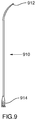
- FIG. 9 illustrates a dilator 910 comprising a tip 912 at the distal end thereof and a proximal hub 914 .
- Dilator 910 may be useful when approaching the heart via the IVC due to the shape thereof.
- Dilator 910 may have one or more radiopaque markers or reference electrodes.
- dilator 910 may define a lumen sized to allow for passage of said dilator over a guidewire or for delivery of Apparatus 102 through said dilator.
- FIGS. 10A, 10B and 10C show alternate embodiments of dilator shapes that may be useful when approaching the heart via the SVC.
- performing a trans-septal perforation utilizing a sheath and dilator typically involves several steps, including positioning the energy delivery device against the septum and advancing the dilator and/or sheath across the septum. Each of these steps may require the dilator to be configured in a specific manner in order to perform the desired function.
- a dilator as shown in FIG. 10A ( 1010 ) or 10 B ( 1020 ) may be employed. Both of these dilators comprise distal tips ( 1012 and 1022 , respectively) that are shaped so as to position the energy delivery device appropriately against the septum when the heart is approached via the SVC.
- the dilator and/or sheath may be advanced across the perforation into the left atrium.
- a dilator that can transmit a longitudinal force applied at a proximal end thereof into a force directed at the perforation in order to dilate the perforation sufficiently.
- a dilator 1030 as illustrated in FIG. 10C , may be used.
- Dilator 1030 comprises a distal tip 1032 with a relatively gentle curve (less than 90 degrees) that lends itself to transmitting mechanical force applied at a proximal end of the dilator to advance the dilator through the perforation.
- the apparatus comprising the energy delivery device may serve to act as a rail to prevent dilator 1030 from slipping down the septum.
- dilator 1010 may be used to advance the dilator and/or sheath through the perforation.
- the dilator and/or sheath may flex and push against the free wall of the right atrium, thereby providing back support and directing force towards the septum.
- the specific curve used in this embodiment may depend on the specific geometry of the right atrium of the patient.
- Any of dilators 1010 , 1020 and 1030 may comprise hubs 914 as well as radiopaque markers and/or reference electrodes.
- one or more of the sheath and dilator may be steerable and/or articulating, whereby a shape of the sheath or dilator may be adjusted during the course of the procedure. This may allow for a user to define the precise curve required for each step of the trans-septal perforation.
- FIGS. 11 and 12 there is illustrated Apparatus 102 inserted through dilator 910 and sheath 800 within a heart 1100 of a patient.
- the heart has been approached via the inferior vena cava.
- FIGS. 13 and 14 provide illustrations of apparatus 102 inserted into the heart via the superior vena cava.
- FIGS. 13A and 14A show apparatus 102 inserted through dilator 1010 while FIGS. 13B and 14B show apparatus 102 inserted through dilators 1020 and 1030 , respectively.
- the dilators are inserted within sheath 810 .
- embodiments of the present invention provide a method of surgical perforation via the delivery of electrical, radiant or thermal energy.
- the method may typically involve at least the following steps: introducing an apparatus comprising an energy delivery device into a patient's heart via the patient's superior vena cava; positioning the energy delivery device at a first location adjacent the material to be perforated; and perforating the material by delivering energy via the energy delivery device; wherein the energy is selected from the group consisting of electrical energy, radiant energy and thermal energy.
- operational steps 1600 for a method of creating a trans-septal perforation in accordance with an embodiment of the invention are outlined in flowchart form in FIGS. 16A and 16B .
- the apparatus, dilator and sheath may be introduced into the heart via the SVC (step 1601 ).
- the heart may be accessed via the IVC, as shown in FIGS. 11 and 12 .
- a guiding sheath and dilator with a lumen sufficient to accommodate the outer diameter of the Apparatus 102 may be introduced into a patient's vasculature.
- the procedure may be performed without a sheath and/or dilator.
- the method comprises steps of introducing one or more devices and/or apparatuses into the patient's vasculature and advancing the devices/apparatuses through the vasculature into the patient's heart.
- Access to the vasculature may be achieved through a variety of veins large enough to accommodate the guiding sheath and dilator and the present invention is not limited in this regard.
- the guiding sheath and dilator may be advanced together through the vasculature. In one embodiment, illustrated in FIGS. 11 and 12 , they approach the heart from the Inferior Vena Cava (IVC) 1106 and proceed into the Superior Vena Cava (SVC) 1108 of the heart 1100 . In accordance with this embodiment, access to the vasculature may be gained via the femoral vein. The sheath and dilator may then be withdrawn from the SVC 1108 , into the right atrium 1110 . In another embodiment, illustrated in FIGS.
- the guiding sheath and dilator approach the heart via the SVC and proceed directly into the right atrium.
- access to the vasculature may be gained via one or more of the subclavian vein, the brachial vein, the axillary vein and the jugular vein.
- methods that include introducing the apparatus, sheath and/or dilator via the Superior Vena Cava, as illustrated in FIGS. 13-14 should not be confused with IVC-approach methods where the distal parts of the guiding sheath and dilator temporarily entering the SVC from an inferior approach.
- Contrast agent may be delivered through the dilator while positioning the dilator and sheath along the atrial septum 1102 .
- the sheath and dilator are now positioned within the right atrium 1110 of heart 1100 so that the tip of the dilator is located against the upper region of the atrial septum 1102 (step 1603 ).
- apparatus 102 can be advanced through the dilator until functional tip region 110 is located distally to the tip of the dilator (step 1604 ).
- Distal region 106 of apparatus 102 is pliable so that the curve 115 straightens out within the dilator and takes on the shape of the dilator as it is advanced to the atrial septum 1102 .
- Apparatus 102 is coupled to the ECG recorder 126 and an ECG tracing monitored through energy delivery device 112 , known to those of ordinary skill in the art, may be shown on ECG recorder 126 . The technique for obtaining an ECG tracing was previously described.
- apparatus 102 , the dilator and the sheath are now dragged along the atrial septum 1102 while monitoring the ECG tracing on the ECG recorder 126 (step 1606 ).
- Confirmation of the position of energy delivery device 112 of apparatus 102 against the fossa ovalis 1104 is made once a distinctive change in the ECG tracing on ECG recorder 126 is observed. This is due to energy delivery device 112 advancing over the region of the fossa ovalis 1104 which is membranous in comparison with the muscular atrial septum 1102 .
- ECG signal recorded by a surgical device while on the membranous fossa ovalis will be damped in comparison with the ECG signal recorded on the muscular areas of the atrial septum or atrial walls.
- This difference in ECG signal may be useful in locating the region of the fossa ovalis as a surgical device is positioned within a heart.
- ECG may be displayed on a screen and/or printed on a chart, for example. The distinctive change may be signaled for observation as well using an alarm such as an audible or visual signal.
- radiopaque contrast agent or dye delivered through apparatus 102 will be directed through the openings 109 in functional tip region 110 into the tissue of the fossa ovalis 1104 in order to stain the tissue and make it more visible under radiographic imaging (step 1608 ).
- the stained region of the fossa ovalis 1104 can be seen as a dark patch in contrast to the atrial septum 1102 , which appears as a lighter color.
- Functional tip region 110 may now be easily directed towards the fossa ovalis 1104 .
- one or more of the dilator, sheath and apparatus may be shaped and or configured such that, upon positioning the apparatus within the right atrium 1110 , functional tip region 110 may be positioned at an angle of about 80 degrees to about 100 degrees relative to the fossa ovalis 1104 . In further embodiments, functional tip region 110 may be positioned substantially perpendicularly relative to the fossa ovalis 1104 . Such a position may be achieved, for example, by using dilators 1010 or 1020 , as shown in FIGS. 13A and 13B .
- apparatus 102 may also be confirmed by monitoring pressure at the functional tip region 110 (step 1610 ).
- Apparatus 102 is coupled to external pressure transducer 121 and a right atrial pressure contour, known to those of ordinary skill in the art, may be displayed on monitoring system 125 .
- the technique for obtaining a pressure contour was previously described.
- the position of functional tip region 110 and energy delivery device 112 may be additionally confirmed using an imaging modality such as fluoroscopy.
- an imaging modality such as fluoroscopy.
- radiopaque markings associated with distal region 106 of apparatus 102 may be aligned with a radiopaque marker located distally on the dilator such that functional tip region 110 of apparatus 102 is located at the fossa ovalis 1104 .
- radiopaque markings associated with distal region 106 of apparatus 102 may be aligned with a radiopaque marker located distally on the sheath such that functional tip region 110 of apparatus 102 is located at the fossa ovalis 1104 (step 1612 ).
- step 1606 The position of functional tip region 110 of apparatus 102 is evaluated and if the desired position is not confirmed (step 1614 , No branch), step 1606 may be repeated. If confirmed (step 1614 , Yes branch), energy may be delivered to create the perforation.
- generator 128 may be activated and RF energy may be delivered through apparatus 102 to make a perforation (step 1616 ).
- the perforation may alternatively be created using radiant (e.g. laser) or thermal energy.
- functional tip region 110 of apparatus 102 is thereafter advanced through the perforation and into a second location (step 1618 ). Advancement may be monitored under fluoroscopy using radiopaque markings on the distal region 106 of apparatus 102 .
- the second location is the left atrium 1112 of the heart.
- the distal region 106 of apparatus 102 is advanced incrementally into the left atrium 1112 through the dilator, for example, in about 1 cm (about 0.39′′) increments.
- the curve portion 115 of distal region 106 of apparatus 102 establishes its curved shape within the left atrium 1112 .
- the distal tip of apparatus 102 may be directing in a desired direction, for example away from cardiac structures, following perforation of the septum.
- An orientation indicator located on apparatus 102 may be monitored in order to determine the direction of the distal tip of apparatus 102 .
- the position of depth markings 113 of apparatus 102 relative to the proximal hub of the dilator can be used as a guide.
- advancement of perforating apparatus 102 can be controlled by monitoring radiopaque markings on the distal region 106 of apparatus 102 under fluoroscopy.
- the evaluation of pressure contours from the left atrium via pressure transducer 121 can be performed.
- Apparatus 102 may remain coupled to external pressure transducer 121 so that a pressure contour at the second location can be measured and/or monitored confirming the desired location of the distal region following the perforation.
- the evaluation of the ECG tracing (step 1622 ) can be performed.
- Apparatus 102 remains coupled to ECG recorder 126 so that an ECG tracing at the second location can be monitored.
- a left atrial pressure contour known to those of ordinary skill in the art, will be shown on monitoring system 125 .
- a left atrial ECG tracing known to those of ordinary skill in the art, will be shown on the ECG recorder 126 .
- apparatus 102 may be retracted into the right atrium 1110 (step 1626 ) and may be repositioned for another perforation attempt (step 1606 ). If the perforation is successfully made in the correct location (step 1624 , Yes branch), distal region 106 of apparatus 102 may be further advanced through the perforation. In some embodiments, when apparatus 102 is fully inserted into the dilator, hub 114 of the apparatus 102 will be flush against the proximal hub of the dilator, and no depth markings 113 of apparatus 102 will be visible (step 1628 , FIG. 16B ). When fully inserted, apparatus 102 provides sufficient support to permit the dilator to be advanced over it through the perforation.
- the dilator may be advanced through the perforation by applying a longitudinal force to the proximal end of the dilator. If the heart has been approached via the IVC, this longitudinal force may directly advance the dilator through the perforation. However, in some embodiments whereby the heart has been approached via the SVC, applying a longitudinal force may push the dilator down along the septum rather than through the perforation. In such embodiments, the dilator may be designed in such a way so that application of a longitudinal force onto a proximal end of the dilator may advance the distal end of the dilator through the perforation. For example, in FIG.
- dilator 1010 is shaped such that application of a longitudinal, downward force onto a proximal end of the dilator will cause a portion ( 1016 in FIG. 10A ) of dilator 1010 to push against the free atrial wall. This in turn will transmit the longitudinal force in a lateral direction, thus forcing the distal end of dilator 1010 through the perforation.
- dilator 1030 may comprise a gentle curve which lends itself to transmitting mechanical force, such that the longitudinal force applied at a proximal end of the dilator will advance the distal end through the perforation.
- apparatus 102 may serve as a rail to support dilator 1030 and to ensure that dilator 1030 does not slip down the septal wall.
- hub 114 of apparatus 102 may be fixed in place spatially, and both the proximal hub 914 of the dilator and proximal hub 804 of the sheath may be incrementally advanced forward, together, thus sliding the dilator and sheath over apparatus 102 (step 1630 ).
- the distal tip of the dilator and the distal tip of the sheath may be monitored under fluoroscopy as they are advanced over apparatus 102 and, once the tip of the dilator has traversed the perforation and has advanced into the left atrium 1112 , the tip of the sheath may then be advanced over the dilator, across the perforation and into the left atrium 1112 as well (step 1632 ).
- hub 114 of apparatus 102 may all be advanced forward together, for example under fluoroscopy. Forward momentum will cause the distal tip of the dilator to traverse the perforation, advancing into the left atrium 1112 . The distal tip of the sheath will follow over the dilator, across the perforation and into the left atrium 1112 .
- apparatus 102 , the dilator and the sheath may each be advanced independently through the perforation. For example, the sheath may be advanced prior to the dilator.
- step 1634 the positions of distal region 106 of apparatus 102 , the distal tip of the dilator and the distal tip of the sheath may be confirmed, for example, under fluoroscopy, to be in the left atrium 1112 . If not in the desired location (step 1636 ), step 1630 may be repeated. If the positions are confirmed (step 1636 ), apparatus 102 and the dilator may now be respectively withdrawn outside the body, for example under fluoroscopic guidance (step 1638 ). While maintaining the position of the distal tip of the dilator and the distal tip of the sheath in the left atrium 1112 , apparatus 102 may be withdrawn.
- the dilator may then be withdrawn outside the body under fluoroscopic guidance, while maintaining the position of the distal tip of the sheath in the left atrium 1112 .
- the sheath may assume its original shape once the dilator is withdrawn. In other words, while the dilator is located within the sheath lumen, the sheath may conform to the shape of the dilator. However, once the dilator is removed, the sheath may revert to its original shape, i.e. the shape it had prior to receiving the dilator within the sheath.
- a contrast agent may now be injected through the sheath into the left atrium 1112 , blood may be aspirated through the sheath from the left atrium 1112 , or other devices (for example treatment devices or diagnostic devices) or treatment compositions may be introduced into the left atrium 1112 through the perforation (for example, through the sheath).
- a dilator having a first shape may be used to facilitate positioning of apparatus 102 adjacent the fossa ovalis or other material to be perforated.
- a dilator having a second shape may be used to facilitate advancement of the dilator across the perforation.
- These two dilator shapes may be achieved in a number of ways.
- two separate dilators may be used.
- One embodiment may comprise two dilators which may be exchanged during the course of the procedure. In other words, one dilator may be used to position the apparatus for perforation and, after perforation has been completed, the dilator may be exchanged for a second dilator configured to facilitate advancement of the dilator across the perforation.
- One method of using more than one dilator includes the steps of (a) from a superior approach, advancing a first dilator, which has a shape for facilitating positioning of its distal end against tissue, until the first dilator's distal end is adjacent the tissue, (b) using an electrosurgical apparatus positioned through the first dilator to create a perforation by delivering energy to the tissue, and advancing the distal end of the electrosurgical apparatus through the perforation, and (c) withdrawing the first dilator, and advancing over the electrosurgical apparatus a second dilator (configured for facilitating advancement of the second dilator through the perforation) wherein the outer diameter of the second dilator is equal to or less than that of the first dilator.
- positioning the first dilator's distal end adjacent the tissue may include positioning near the issue or against the tissue.
- adjacent can be taken to mean either close to, or against.
- the dilator is touching and tenting the tissue.
- the above described method of using more than one dilator includes an embodiment which utilizes an electrosurgical apparatus 102 and a delivery system comprising at least two dilators wherein a first dilator 1020 B is configured for facilitating positioning of the electrosurgical apparatus 102 adjacent the tissue and wherein a second dilator 1030 is configured for advancement through a perforation in the tissue.
- a first dilator 1020 B is configured for facilitating positioning of the electrosurgical apparatus 102 adjacent the tissue and wherein a second dilator 1030 is configured for advancement through a perforation in the tissue.
- the term “configured” is intended to mean having an appropriate shape and/or stiffness.
- This method comprises the steps of: (a) advancing the first dilator 1020 B into the heart 1100 of the patient, from a superior approach, until a distal end of the first dilator 1020 B is adjacent the tissue; (b) using the electrosurgical apparatus, which is positioned through the first dilator, to create a perforation in the tissue by delivering electrical energy to the tissue; (c) advancing the distal end of the electrosurgical apparatus (e.g. functional tip 110 of FIG. 17B ) through the perforation; (d) withdrawing the first dilator 1020 B; and (e) advancing the second dilator 1030 ( FIG.
- the tissue is an atrial septum 1102 , in particular, a fossa ovalis 1104 .
- the method of using more than one dilator typically includes the electrosurgical apparatus 102 comprising an energy delivery device 112 at a distal end thereof, and wherein step (b) includes, prior to delivering energy, positioning the energy delivery device 112 adjacent the tissue. Following the positioning of energy delivery device, energy may be delivered through the energy delivery device 112 to the tissue to create the perforation in the tissue.
- the method typically includes a step (e) of advancing the second dilator through the perforation to thereby dilate the perforation.
- a taper at a distal tip of the second dilator 1030 has a more gradual slope than a taper at a distal tip of the first dilator.
- the taper at the distal tip of the first dilator has a length of about 0.5 cm to about 1 cm.
- the taper at the distal tip of the second dilator has a length of about 2 to about 5 cm. while in other examples, the taper at the distal tip of the second dilator has a length of about 3 to about 4 cm. Having a shorter taper provides for better support for puncturing by the electrosurgical apparatus 102 while a longer and more gradual taper provides for better dilation since the tissue can be dilated using less applied longitudinal force.
- the first dilator has a stiffness which facilitates it being positioned
- the second dilator is stiffer than the first dilator, having a stiffness which facilitate transmitting mechanical force applied at a proximal end of the second dilator to thereby advance the second dilator through the perforation.
- the delivery system further comprises a sheath, and the outer diameter of the first dilator and the outer diameter of the second dilator are substantially equal and correspond with an inner diameter of the sheath.
- the outer diameters of the dilators corresponding with the inner diameter of a sheath should not be interpreted as meaning the outer diameters of the dilators have to be exactly equal to the inner diameter of the sheath, but rather that the dilators fit within the sheath for proper functioning.
- the outer diameter of the first dilator fits closely to the inner diameter of the sheath.
- step (a) further comprises positioning the first dilator 1020 B such that a distal end of the first dilator is oriented at an oblique angle relative to a surface of the atrial septum 1102 .
- This use of the term “oblique angle” is intended to describe that the first dilator is not perpendicular or parallel to the surface of the atrial septum.
- step (a) comprises positioning the first dilator 1020 B such that a distal end of the first dilator is oriented at an angle of about 20 degrees to about 70 degrees relative to a surface of the atrial septum 1102 .
- step (c) further includes positioning the second dilator 1030 ( FIG. 17B ) such that a distal end of the second dilator is oriented at an angle of about 20 degrees to about 70 degrees relative to a surface of the atrial septum 1102 .
- the first dilator 1020 B has a flexural rigidity of about 3 Ncm 2 to about 7 Ncm 2 and the second dilator 1030 has a flexural rigidity of about 23 Ncm 2 to about 28 Ncm 2 , and in some such embodiments, the first dilator and is comprised of LDPE and the second dilator is comprised of HDPE. In the embodiments shown in FIGS.
- the first dilator 1020 B has a distal tip with a curve of less than 90 degrees to facilitate using it with the electrosurgical apparatus which is stiff enough to function as a rail for advancing other devices thereover
- the second dilator 1030 has a distal tip with a curve of less than 90 degrees to facilitate transmitting mechanical force applied at a proximal end of the second dilator to thereby advance the second dilator through the perforation.
- the delivery system (illustrated in FIGS. 17A and 17B ) further comprises a sheath and step (a) further comprises using the sheath 810 for positioning the first dilator 1020 B, wherein the sheath 810 and the first dilator are supported by a superior vena cava 1108 and step (e) includes using the sheath 810 for positioning the second dilator 1030 wherein the sheath 810 and the second dilator are supported by the superior vena cava 1108 .
- the tissue is an atrial septum 1102 of the heart 1100 and step (a) further includes positioning the first dilator 1020 such that a distal end of the first dilator 1020 is oriented at an angle of about 80 degrees to about 100 degrees relative to a surface of the atrial septum 1102 ( FIG. 13B ). In some such embodiments, the distal end of the first dilator 1020 is oriented substantially perpendicularly relative to the surface of the atrial septum 1102 .
- Typical embodiments include step (e) further comprising positioning the second dilator 1030 such that a distal end of the second dilator is oriented at an angle of less than 90 degrees relative to the surface of the atrial septum 1102 ( FIG. 14B ).
- the electrosurgical apparatus 102 is bent at an angle greater than 90 degrees when it is being positioned.
- the electrosurgical apparatus 102 used in such embodiments is sufficiently flexible to facilitate this bending.
- the first dilator has a distal tip with a curve greater than 90 degrees (e.g. FIGS. 10A and 10B ) to facilitate positioning the distal end of the first dilator at a generally perpendicular approach when approaching from the superior vena cava (e.g. FIGS.
- the second dilator 1030 has a distal tip 1032 with a curve of less than 90 degrees (e.g. FIG. 10C ) to facilitate transmitting mechanical force applied at a proximal end of the second dilator to thereby advance the second dilator through the perforation.
- the first dilator 1020 is typically flexible enough to conform to the shape of the sheath 810 being used to engage the atrial septum when advancing from the superior vena cava.
- the second dilator 1030 which is used to improve or increase dilation, approaches the surface of the tissue from an angle of about 45 degrees, and is typically comprised of a material stiff enough to provide support to compensate for having a longer distal taper (relative to the first dilator).
- another embodiment may comprise a first, more flexible dilator configured to facilitate advancement of the dilator through the perforation.
- a second, stiffer dilator may be located within a lumen defined by the more flexible dilator.
- the stiffer dilator may be configured to facilitate positioning of the apparatus for perforation.
- the stiffer dilator may be inserted within the more flexible dilator in order to position the apparatus for perforation.
- the stiffer dilator may be retracted, thus allowing the more flexible dilator to assume its natural shape, configured to allow for advancement of the dilator through the perforation.
- elongated support member such as a stylet
- the elongated support may be inserted into a lumen and retracted after tissue penetration is completed.
- the dilator may be configured such that a user can modify the shape of the dilator during the course of the procedure.
- the dilator may have a single configuration throughout the procedure, as illustrated, for example, in FIGS. 13A and 14A .
- the present invention in various embodiments thus provides a device and method that is capable of creating a perforation while determining a position of the device in response to action potentials or measured voltage at a location in the heart as well as determining a position of the device in response to pressure at a location in the body.
- the present invention decreases the risk of inadvertent and unwanted cardiac injury associated with creating the perforation.
- One means for decreasing the risk of unwanted injury comprises a curve at the distal end of the device.
- the present invention also provides a method for staining the area to be perforated in order to make it easier to locate during the perforation.
- embodiments of the present invention provide a method for delivering a dilator and sheath over the device after the perforation.
- the perforation may be created by the application of energy produced by a generator and delivered to an active tip on the device.
- the energy may be selected from the group consisting of electrical energy (various frequencies), radiant energy (e.g. laser) and thermal energy, amongst others.
- a means for determining the position of the device may comprise an ECG measuring device for monitoring action potentials or measured voltage through an active electrode in a unipolar or bipolar manner and displaying the ECG tracings on an ECG recorder.
- a means for determining the position of the device may also comprise a pressure transmitting lumen that may be releasably coupled to an external pressure transducer.
- the means for determining the position of the device in response to pressure comprises a transducer located on the device proximal to the functional tip.
- the device of the invention may be useful as a substitute for a traditional trans-septal needle to create a trans-septal perforation.
- Some embodiments of the device of the present invention may have a soft and curved distal region with a functional tip that uses RF energy to create a perforation across a septum, making the procedure more easily controlled and less operator dependent than a trans-septal needle procedure.
- the soft distal region of the device may reduce incidents of vascular trauma as the device is advanced through the vasculature.
- the application of RF energy may be controlled via an electric generator, eliminating the need for the operator to subjectively manage the amount of force necessary to cross the septum with a traditional needle.
- the present invention may reduce the danger of applying too much mechanical force and injuring the posterior wall of the heart.
- the present invention also provides a method for the creation of a perforation in, for example, an atrial septum.
- ECG as well as pressure monitoring may be advantageous in this procedure, as there is the possibility of inadvertently perforating the aorta due to its proximity to the atrial septum.
- Electrical action potential or voltage measurements displayed as ECG tracings allow the operator to position the device accurately at the fossa ovalis on the septum as well as confirm that the distal end of the device has entered the left atrium, and not the aorta or another undesirable location in the heart.
- pressure measurements allow the operator to confirm that the distal end of the device has entered the left atrium, and not the aorta, or another undesirable location in the heart.
- Staining the atrial septum may also be advantageous in this procedure, as it easily identifies the region of the atrial septum (fossa ovalis) to be perforated.
- the device may also be visible using standard imaging techniques; however the ability to monitor both ECG and pressure provides the operator with a level of safety and confidence that would not exist using only these techniques. It should be noted, however, that a method of the present invention may be practiced without any or all of pressure monitoring, ECG monitoring and staining and is thus intended to comprise, in a basic form, a method of creating a perforation in a tissue utilizing any intravascular approach.
- the heart is approached via the inferior vena cava (IVC) (an ‘inferior’ approach).
- the device may be introduced into the patient's vasculature via the femoral vein and via the inferior vena cava.
- the heart may be approached via the superior vena cava (SVC) (a ‘superior’ approach).
- SVC superior vena cava
- Such embodiments may be useful in instances where introduction via the IVC is contra-indicated. For example, occasionally, due to abnormalities of the venous system such as azygous continuation of the inferior vena cava or thrombosis or obliteration of the iliofemoral veins it may not be possible to gain access to the right atrium using a femoral approach.
- the standard femoral transvenous approach to the atrial septum for trans-septal access may be difficult in situation where the cardiac anatomy is grossly distorted such as in patients with longstanding and marked elevation of left atrial and pulmonary artery pressures, or patients who have previously undergone cardiac surgery.
- Gaining trans-septal access from the femoral approach may also be difficult in patients with dextrocardia, a condition in which the heart is located on the right side of the chest rather than the left and in whom there is significant variation in the orientation of the atrial septum.
- trans-septal punctures would benefit from a device that utilizes a non-femoral, i.e. superior, approach and which is more reliable and user-friendly than the trans-septal needle.
- the patient population discussed above would benefit from a device and technique for trans-septal perforation that allows for a multiplicity of uncomplicated intravascular approaches as well as providing a more controlled method of perforation.
- access to the patient's vasculature may be achieved through one or more of a brachial vein, an axillary vein, a subclavian vein and a jugular vein.
- the device In order to create the perforation, it may be desirable to position the device at a specific orientation relative to the material to be perforated. For example, the device may be oriented at an angle of between about 80 to about 100 degrees relative to the fossa ovalis. Achieving such an orientation using a superior approach may require the use of dilators and/or sheaths having appropriate shapes, as have been described herein above.
- the present invention also provides a method for delivering the dilator and sheath over the device into the left atrium once a successful perforation has been created.
- An application of a method aspect of the present invention may involve the implantation of a device, such as an implantable pressure monitor or other sensor into the left atrium of a patient's heart.
- a perforation may be created between the right and left atria of a patient's heart utilizing a superior intravascular approach, for example through a subclavian vein.
- an implantable device may be inserted through to the left atrium and implanted at a desired location.
- the implantable device may be initially mounted on one of an electrosurgical device, a dilator, a sheath or a guidewire, thus obviating the need for an additional device to insert the implantable device.
- a pressure sensor or other device may be inserted into the left atrium after the creation of a perforation in order to monitor pressure or some other physiological parameter without being permanently implanted.
- the device may be used to monitor some parameter and may then be removed, in the same procedure, without being permanently implanted into the patient. All of these applications are intended to be exemplary only and are not intended to limit the scope of the present invention in any way.
- any of the hubs referred to throughout this specification may be removable in order to facilitate exchange or removal of any devices or components during the course of a procedure.
- a device may be made within the scope of the invention without a curve portion of the distal region.
- a pressure sensing mechanism for positioning the device is optional and, in other instances, the ECG monitoring feature is optional.
- Embodiments of the present invention are useful, for example, for the perforation of a patient's heart tissue when an inferior approach to the heart is contraindicated.
- a heart tissue perforation can be accomplished introducing an electrosurgical apparatus via a superior approach.
- the apparatus may then be positioned and a controlled amount of non-mechanical energy may then be delivered to tissue at a treatment site to create the perforation or puncture.
Landscapes
- Health & Medical Sciences (AREA)
- Life Sciences & Earth Sciences (AREA)
- Engineering & Computer Science (AREA)
- Surgery (AREA)
- Public Health (AREA)
- Veterinary Medicine (AREA)
- Heart & Thoracic Surgery (AREA)
- Biomedical Technology (AREA)
- Animal Behavior & Ethology (AREA)
- General Health & Medical Sciences (AREA)
- Physics & Mathematics (AREA)
- Plasma & Fusion (AREA)
- Nuclear Medicine, Radiotherapy & Molecular Imaging (AREA)
- Otolaryngology (AREA)
- Medical Informatics (AREA)
- Molecular Biology (AREA)
- Anesthesiology (AREA)
- Cardiology (AREA)
- Hematology (AREA)
- Vascular Medicine (AREA)
- Surgical Instruments (AREA)
Abstract
Description
Claims (20)
Priority Applications (2)
| Application Number | Priority Date | Filing Date | Title |
|---|---|---|---|
| US15/463,913 US11039880B2 (en) | 2003-01-21 | 2017-03-20 | Method of surgical perforation via the delivery of energy |
| US17/350,434 US20210307823A1 (en) | 2003-01-21 | 2021-06-17 | Method of surgical perforation via the delivery of energy |
Applications Claiming Priority (8)
| Application Number | Priority Date | Filing Date | Title |
|---|---|---|---|
| US10/347,366 US7112197B2 (en) | 2003-01-21 | 2003-01-21 | Surgical device with pressure monitoring ability |
| US10/666,301 US7048733B2 (en) | 2003-09-19 | 2003-09-19 | Surgical perforation device with curve |
| US10/666,288 US20040143262A1 (en) | 2003-01-21 | 2003-09-19 | Surgical perforation device and method with pressure monitoring and staining abilities |
| US10/760,479 US7270662B2 (en) | 2004-01-21 | 2004-01-21 | Surgical perforation device with electrocardiogram (ECG) monitoring ability and method of using ECG to position a surgical perforation device |
| US52275304P | 2004-11-03 | 2004-11-03 | |
| US11/265,304 US7947040B2 (en) | 2003-01-21 | 2005-11-03 | Method of surgical perforation via the delivery of energy |
| US13/113,326 US9597146B2 (en) | 2003-01-21 | 2011-05-23 | Method of surgical perforation via the delivery of energy |
| US15/463,913 US11039880B2 (en) | 2003-01-21 | 2017-03-20 | Method of surgical perforation via the delivery of energy |
Related Parent Applications (1)
| Application Number | Title | Priority Date | Filing Date |
|---|---|---|---|
| US13/113,326 Continuation-In-Part US9597146B2 (en) | 2003-01-21 | 2011-05-23 | Method of surgical perforation via the delivery of energy |
Related Child Applications (1)
| Application Number | Title | Priority Date | Filing Date |
|---|---|---|---|
| US17/350,434 Continuation US20210307823A1 (en) | 2003-01-21 | 2021-06-17 | Method of surgical perforation via the delivery of energy |
Publications (2)
| Publication Number | Publication Date |
|---|---|
| US20170189113A1 US20170189113A1 (en) | 2017-07-06 |
| US11039880B2 true US11039880B2 (en) | 2021-06-22 |
Family
ID=59236142
Family Applications (2)
| Application Number | Title | Priority Date | Filing Date |
|---|---|---|---|
| US15/463,913 Expired - Lifetime US11039880B2 (en) | 2003-01-21 | 2017-03-20 | Method of surgical perforation via the delivery of energy |
| US17/350,434 Abandoned US20210307823A1 (en) | 2003-01-21 | 2021-06-17 | Method of surgical perforation via the delivery of energy |
Family Applications After (1)
| Application Number | Title | Priority Date | Filing Date |
|---|---|---|---|
| US17/350,434 Abandoned US20210307823A1 (en) | 2003-01-21 | 2021-06-17 | Method of surgical perforation via the delivery of energy |
Country Status (1)
| Country | Link |
|---|---|
| US (2) | US11039880B2 (en) |
Families Citing this family (12)
| Publication number | Priority date | Publication date | Assignee | Title |
|---|---|---|---|---|
| US10478251B2 (en) * | 2006-12-19 | 2019-11-19 | Srgi Holdings Llc | Steerable and controllable medical laser fibers |
| US11224725B2 (en) | 2017-12-05 | 2022-01-18 | Baylis Medical Company Inc. | Transseptal guide wire puncture system |
| US11058829B1 (en) * | 2019-03-01 | 2021-07-13 | Michael B. McDonald | Injection device and method |
| US12156642B2 (en) | 2019-04-29 | 2024-12-03 | Boston Scientific Medical Device Limited | Transseptal systems, devices and methods |
| JP7791834B2 (en) | 2020-11-12 | 2025-12-24 | 株式会社カネカ | Lancing Device |
| WO2022176604A1 (en) | 2021-02-22 | 2022-08-25 | 株式会社カネカ | Puncturing device |
| JP7788555B2 (en) * | 2021-11-30 | 2025-12-18 | ボストン サイエンティフィック メディカル デバイス リミテッド | System for tissue puncture |
| EP4489674A1 (en) * | 2022-03-11 | 2025-01-15 | Boston Scientific Medical Device Limited | Medical devices |
| US12490963B2 (en) | 2022-12-27 | 2025-12-09 | Transmural Systems Llc | Tissue cutting systems and methods |
| CN121038709A (en) * | 2022-12-27 | 2025-11-28 | 透壁系统有限责任公司 | Catheter and actuator systems and methods |
| WO2024145061A1 (en) | 2022-12-27 | 2024-07-04 | Transmural Systems Llc | Catheter and actuator systems and methods |
| US20240407705A1 (en) * | 2023-06-09 | 2024-12-12 | Boston Scientific Scimed, Inc. | Shaped dilator for transseptal puncture and electroanatomical mapping |
Citations (8)
| Publication number | Priority date | Publication date | Assignee | Title |
|---|---|---|---|---|
| US5364393A (en) * | 1990-07-02 | 1994-11-15 | Heart Technology, Inc. | Tissue dissipative recanalization catheter |
| US5575766A (en) * | 1993-11-03 | 1996-11-19 | Daig Corporation | Process for the nonsurgical mapping and treatment of atrial arrhythmia using catheters guided by shaped guiding introducers |
| US20020169377A1 (en) * | 2000-04-13 | 2002-11-14 | Khairkhahan Alexander K. | Method and apparatus for accessing the left atrial appendage |
| US20030225392A1 (en) | 2002-05-31 | 2003-12-04 | Kimberly-Clark Worldwide, Inc. | Low profile transpyloric jejunostomy system and method to enable |
| US20140296769A1 (en) * | 2013-03-28 | 2014-10-02 | Silk Road Medical, Inc. | Methods and Systems for Establishing Retrograde Carotid Arterial Blood Flow |
| US20160220741A1 (en) * | 2014-03-21 | 2016-08-04 | Route 92 Medical, Inc. | Rapid aspiration thrombectomy system and method |
| US20190021763A1 (en) * | 2017-07-20 | 2019-01-24 | Terumo Kabushiki Kaisha | Introducer sheath and introducer |
| US20190247035A1 (en) * | 2016-10-25 | 2019-08-15 | Muffin Incorporated | Vascular anchoring introducer sheath |
Family Cites Families (6)
| Publication number | Priority date | Publication date | Assignee | Title |
|---|---|---|---|---|
| US6565562B1 (en) * | 1997-06-27 | 2003-05-20 | Baylis Medical Company Inc. | Method for the radio frequency perforation and the enlargement of a body tissue |
| US6328699B1 (en) * | 2000-01-11 | 2001-12-11 | Cedars-Sinai Medical Center | Permanently implantable system and method for detecting, diagnosing and treating congestive heart failure |
| ATE333843T1 (en) * | 2000-12-11 | 2006-08-15 | Bard Inc C R | MAPPING DEVICE |
| US6666862B2 (en) * | 2001-03-01 | 2003-12-23 | Cardiac Pacemakers, Inc. | Radio frequency ablation system and method linking energy delivery with fluid flow |
| US6814733B2 (en) * | 2002-01-31 | 2004-11-09 | Biosense, Inc. | Radio frequency pulmonary vein isolation |
| ATE506891T1 (en) * | 2002-08-24 | 2011-05-15 | St Jude Medical Atrial Fibrill | METHOD AND DEVICE FOR LOCALIZING THE FOSSA OVALIS AND PERFORMING A TRANSSEPTAL PUNCTURE |
-
2017
- 2017-03-20 US US15/463,913 patent/US11039880B2/en not_active Expired - Lifetime
-
2021
- 2021-06-17 US US17/350,434 patent/US20210307823A1/en not_active Abandoned
Patent Citations (8)
| Publication number | Priority date | Publication date | Assignee | Title |
|---|---|---|---|---|
| US5364393A (en) * | 1990-07-02 | 1994-11-15 | Heart Technology, Inc. | Tissue dissipative recanalization catheter |
| US5575766A (en) * | 1993-11-03 | 1996-11-19 | Daig Corporation | Process for the nonsurgical mapping and treatment of atrial arrhythmia using catheters guided by shaped guiding introducers |
| US20020169377A1 (en) * | 2000-04-13 | 2002-11-14 | Khairkhahan Alexander K. | Method and apparatus for accessing the left atrial appendage |
| US20030225392A1 (en) | 2002-05-31 | 2003-12-04 | Kimberly-Clark Worldwide, Inc. | Low profile transpyloric jejunostomy system and method to enable |
| US20140296769A1 (en) * | 2013-03-28 | 2014-10-02 | Silk Road Medical, Inc. | Methods and Systems for Establishing Retrograde Carotid Arterial Blood Flow |
| US20160220741A1 (en) * | 2014-03-21 | 2016-08-04 | Route 92 Medical, Inc. | Rapid aspiration thrombectomy system and method |
| US20190247035A1 (en) * | 2016-10-25 | 2019-08-15 | Muffin Incorporated | Vascular anchoring introducer sheath |
| US20190021763A1 (en) * | 2017-07-20 | 2019-01-24 | Terumo Kabushiki Kaisha | Introducer sheath and introducer |
Non-Patent Citations (2)
| Title |
|---|
| Final Office Action of U.S. Appl. No. 13/113,326, dated Jun. 28, 2016. |
| Response to Final Office Action of U.S. Appl. No. 13/113,326, dated Jun. 28, 2016. |
Also Published As
| Publication number | Publication date |
|---|---|
| US20210307823A1 (en) | 2021-10-07 |
| US20170189113A1 (en) | 2017-07-06 |
Similar Documents
| Publication | Publication Date | Title |
|---|---|---|
| US7947040B2 (en) | Method of surgical perforation via the delivery of energy | |
| US9597146B2 (en) | Method of surgical perforation via the delivery of energy | |
| US20210307823A1 (en) | Method of surgical perforation via the delivery of energy | |
| US12558152B2 (en) | Transseptal crossing system for single pass large bore access | |
| US7270662B2 (en) | Surgical perforation device with electrocardiogram (ECG) monitoring ability and method of using ECG to position a surgical perforation device | |
| US7048733B2 (en) | Surgical perforation device with curve | |
| US20040143262A1 (en) | Surgical perforation device and method with pressure monitoring and staining abilities | |
| JP2023153314A (en) | Apparatus and method for puncturing tissue | |
| US20040143261A1 (en) | Surgical device with pressure monitoring ability | |
| US20230329771A1 (en) | Electrosurgical device with sensing | |
| KR102406833B1 (en) | RF ablation catheter for Septal reduction theraphy having cooling effect | |
| JP2020081884A (en) | Rf electrode ablation catheter for treating hypertrophic cardiomyopathy and usage | |
| CN203524766U (en) | Trans-luminal wall-penetration nerve ablation catheter and equipment thereof | |
| EP2401978B1 (en) | Surgical perforation device with ecg monitoring, pressure monitoring, curve and staining abilities | |
| KR102406831B1 (en) | RF ablation catheter for hypertrophic cardiomyopahty | |
| US20240407705A1 (en) | Shaped dilator for transseptal puncture and electroanatomical mapping | |
| US20240245452A1 (en) | Single pass large bore transseptal crossing | |
| US20250127560A1 (en) | Percutaneous vascular access with radiofrequency energy | |
| CN116744849A (en) | microcatheter |
Legal Events
| Date | Code | Title | Description |
|---|---|---|---|
| AS | Assignment |
Owner name: BAYLIS MEDICAL COMPANY INC., CANADA Free format text: ASSIGNMENT OF ASSIGNORS INTEREST;ASSIGNORS:URBANSKI, JOHN PAUL;DICICCO, MATTHEW PAUL JOSEPH;HACHEM, BAHE;AND OTHERS;SIGNING DATES FROM 20170321 TO 20170523;REEL/FRAME:043006/0310 |
|
| STPP | Information on status: patent application and granting procedure in general |
Free format text: DOCKETED NEW CASE - READY FOR EXAMINATION |
|
| STPP | Information on status: patent application and granting procedure in general |
Free format text: NON FINAL ACTION MAILED |
|
| STPP | Information on status: patent application and granting procedure in general |
Free format text: FINAL REJECTION MAILED |
|
| STPP | Information on status: patent application and granting procedure in general |
Free format text: ADVISORY ACTION MAILED |
|
| STPP | Information on status: patent application and granting procedure in general |
Free format text: NOTICE OF ALLOWANCE MAILED -- APPLICATION RECEIVED IN OFFICE OF PUBLICATIONS |
|
| STPP | Information on status: patent application and granting procedure in general |
Free format text: PUBLICATIONS -- ISSUE FEE PAYMENT RECEIVED |
|
| STPP | Information on status: patent application and granting procedure in general |
Free format text: PUBLICATIONS -- ISSUE FEE PAYMENT VERIFIED |
|
| STCF | Information on status: patent grant |
Free format text: PATENTED CASE |
|
| AS | Assignment |
Owner name: BOSTON SCIENTIFIC MEDICAL DEVICE LIMITED, IRELAND Free format text: ASSIGNMENT OF ASSIGNORS INTEREST;ASSIGNOR:BAYLIS MEDICAL COMPANY INC.;REEL/FRAME:060938/0731 Effective date: 20220601 |
|
| FEPP | Fee payment procedure |
Free format text: ENTITY STATUS SET TO UNDISCOUNTED (ORIGINAL EVENT CODE: BIG.); ENTITY STATUS OF PATENT OWNER: LARGE ENTITY |
|
| MAFP | Maintenance fee payment |
Free format text: PAYMENT OF MAINTENANCE FEE, 4TH YEAR, LARGE ENTITY (ORIGINAL EVENT CODE: M1551); ENTITY STATUS OF PATENT OWNER: LARGE ENTITY Year of fee payment: 4 |