US11037337B2 - Method and apparatus for generating measurement plan for measuring X-ray CT - Google Patents
Method and apparatus for generating measurement plan for measuring X-ray CT Download PDFInfo
- Publication number
- US11037337B2 US11037337B2 US16/299,513 US201916299513A US11037337B2 US 11037337 B2 US11037337 B2 US 11037337B2 US 201916299513 A US201916299513 A US 201916299513A US 11037337 B2 US11037337 B2 US 11037337B2
- Authority
- US
- United States
- Prior art keywords
- measurement
- test object
- tolerance information
- volume data
- magnification
- Prior art date
- Legal status (The legal status is an assumption and is not a legal conclusion. Google has not performed a legal analysis and makes no representation as to the accuracy of the status listed.)
- Active, expires
Links
Images


Classifications
-
- G06T11/005—
-
- G—PHYSICS
- G01—MEASURING; TESTING
- G01N—INVESTIGATING OR ANALYSING MATERIALS BY DETERMINING THEIR CHEMICAL OR PHYSICAL PROPERTIES
- G01N23/00—Investigating or analysing materials by the use of wave or particle radiation, e.g. X-rays or neutrons, not covered by groups G01N3/00 – G01N17/00, G01N21/00 or G01N22/00
- G01N23/02—Investigating or analysing materials by the use of wave or particle radiation, e.g. X-rays or neutrons, not covered by groups G01N3/00 – G01N17/00, G01N21/00 or G01N22/00 by transmitting the radiation through the material
- G01N23/04—Investigating or analysing materials by the use of wave or particle radiation, e.g. X-rays or neutrons, not covered by groups G01N3/00 – G01N17/00, G01N21/00 or G01N22/00 by transmitting the radiation through the material and forming images of the material
- G01N23/046—Investigating or analysing materials by the use of wave or particle radiation, e.g. X-rays or neutrons, not covered by groups G01N3/00 – G01N17/00, G01N21/00 or G01N22/00 by transmitting the radiation through the material and forming images of the material using tomography, e.g. computed tomography [CT]
-
- G—PHYSICS
- G01—MEASURING; TESTING
- G01B—MEASURING LENGTH, THICKNESS OR SIMILAR LINEAR DIMENSIONS; MEASURING ANGLES; MEASURING AREAS; MEASURING IRREGULARITIES OF SURFACES OR CONTOURS
- G01B15/00—Measuring arrangements characterised by the use of electromagnetic waves or particle radiation, e.g. by the use of microwaves, X-rays, gamma rays or electrons
-
- G—PHYSICS
- G06—COMPUTING OR CALCULATING; COUNTING
- G06T—IMAGE DATA PROCESSING OR GENERATION, IN GENERAL
- G06T12/00—Tomographic reconstruction from projections
- G06T12/10—Image preprocessing, e.g. calibration, positioning of sources or scatter correction
-
- G—PHYSICS
- G01—MEASURING; TESTING
- G01B—MEASURING LENGTH, THICKNESS OR SIMILAR LINEAR DIMENSIONS; MEASURING ANGLES; MEASURING AREAS; MEASURING IRREGULARITIES OF SURFACES OR CONTOURS
- G01B15/00—Measuring arrangements characterised by the use of electromagnetic waves or particle radiation, e.g. by the use of microwaves, X-rays, gamma rays or electrons
- G01B15/04—Measuring arrangements characterised by the use of electromagnetic waves or particle radiation, e.g. by the use of microwaves, X-rays, gamma rays or electrons for measuring contours or curvatures
-
- G—PHYSICS
- G01—MEASURING; TESTING
- G01N—INVESTIGATING OR ANALYSING MATERIALS BY DETERMINING THEIR CHEMICAL OR PHYSICAL PROPERTIES
- G01N2223/00—Investigating materials by wave or particle radiation
- G01N2223/30—Accessories, mechanical or electrical features
- G01N2223/306—Accessories, mechanical or electrical features computer control
-
- G—PHYSICS
- G06—COMPUTING OR CALCULATING; COUNTING
- G06T—IMAGE DATA PROCESSING OR GENERATION, IN GENERAL
- G06T2211/00—Image generation
- G06T2211/40—Computed tomography
- G06T2211/432—Truncation
Definitions
- the present invention relates to a method and an apparatus for generating a measurement plan for measuring X-ray CT.
- the present invention relates to a method and an apparatus for generating a measurement plan for measuring X-ray CT that is capable of automatically calculating a measurement field of view magnification to ensure measurement accuracy, and that is capable of automatically generating an optimized measurement plan including a measurement field of view that fits as many targeted measurement locations as possible.
- volume data (or a tomographic image) of a test object non-destructively
- an X-ray irradiation is performed while rotating the test object, and in doing so, projection image data is acquired and the volume data is reconstructed from the projection image data.
- a measurement operator measures targeted measurement locations in the volume data.
- the volume data is generated based on the measurement field of view. However, while the measurement locations can be measured accurately when the measurement field of view is smaller, not all targeted measurement locations fit in the measurement field of view and X-ray images may need to be captured a number of times.
- a configuration of a generic measuring X-ray CT apparatus and a measurement procedure for a work piece are described below.
- a generic X-ray CT apparatus which is used for measurement is configured with an enclosure 10 which shields X-rays, a controller 30 , and a control PC 40 .
- the enclosure 10 includes therein: an X-ray tube 12 that fires X-rays 13 , an X-ray detection device 14 detecting the X-rays 13 , a rotary table 16 on which a test object (such as a work piece) W is placed and which rotates the test object W for CT imaging, and an XYZ displacement mechanism 18 adjusting a position or magnification of the test object W which is projected onto the X-ray detection device 14 .
- the controller 30 controls the devices mentioned above, and the control PC 40 issues instructions from a user operation to the controller 30 .
- An X-ray CT control program 42 is running on the control PC 40 and the X-ray CT control program 42 controls each device, displays a projection image of the test object W which is projected onto the X-ray detection device 14 , and generates a tomographic image as volume data from a plurality of projection images of the test object W.
- an X-ray collimator 20 is provided near the X-ray tube 12 .
- the X-ray collimator 20 is configured with upper and lower components made of an X-ray non-transmissible material (such as tungsten) in order to restrict an irradiation range of the X-rays 13 and those components can be shifted in an up-down direction respectively.
- the X-ray collimator 20 can be adjusted from the control PC 40 in accordance with an image capture range of the test object W.
- the X-rays 13 fired from the X-ray tube 12 (X-ray source) pass through the test object W on the rotary table 16 and reach the X-ray detection device 14 .
- the tomographic image of the test object W is generated by obtaining, with the X-ray detection device 14 , transmission images of the test object W in various directions while rotating the test object W.
- the position of the test object W can be shifted and the image capture range (position, magnification) or an image capture angle of the test object W can be adjusted.
- a measurement using such a measuring X-ray CT apparatus is generally performed by the following two procedures.
- the work piece W depicted in FIG. 4A is considered.
- the work piece W has a cylindrical outer shape and has a cylindrical hollow space H on an interior thereof, and a diameter D of the cylinder of the hollow space H is measured.
- a surface of the hollow space (boundary between the material and air) is detected first and a plurality of measurement points (detection points) are obtained.
- a best fit hollow cylinder is created for the cylindrical shape of the hollow space, and then the diameter D is calculated.
- the measurement locations to obtain the set of measurement points it is better to select a measurement location having no deviation in consideration of the cylindrical hollow space, and therefore three measurement locations in a circumferential direction for the respective upper and lower portions of the cylinder (total of six locations) are selected as shown in FIG. 4B .
- the plurality of measurement points can be obtained in one measurement location.
- the measurement magnification for each measurement location must be determined, and tolerance information is used for deriving the measurement magnification.
- the measurement points used in the calculation of the cylindrical diameter D must be found with a higher degree of accuracy than 0.1 mm (0.01 mm for example).
- these measurements are performed on the volume data, and therefore the volume data must have the accuracy required for the measurement.
- the accuracy of the volume data is expressed by a voxel size [mm], and generating volume data having a voxel size of 0.01 mm is considered.
- mag the magnification
- mag fdd fcd ( 1 )
- DetectorWidth a width of the generated volume data is defined as VolumeWidth [pixels]
- VoxelSize a relational expression is expressed below.
- mag DetectorWidth VoxelSize ⁇ VolumeWidth ( 3 )
- the required magnification is 20 times.
- the desired volume data can be generated by changing the position or angle of the rotary table 16 , making adjustment so that the measurement location of the work piece W is displayed at 20 times magnification, and performing a CT scan.
- magnification required for each measurement location is calculated respectively and is brought in line with the largest magnification (highest resolution).
- the surface of the hollow space (boundary between the material and air) is detected first and the plurality of measurement points (detection points) are obtained.
- the set of measurement points On the basis of the set of measurement points, a best fit hollow cylinder is created for the cylindrical shape of the hollow space, and then the diameter D is calculated.
- the measurement operator needs to perform the CT scan after considering the measurement location and measurement accuracy ahead of time, and there are challenges in creating a plan that results in the minimum number of CT scans for the plurality of measurement locations.
- the present invention has been conceived in order to resolve the conventional circumstances described above, and is configured for a measuring X-ray CT apparatus to automatically calculate a measurement field of view magnification that can ensure proper measurement accuracy from information such as a tolerance included in CAD data of a test object, and to automatically generate an optimized measurement plan including a measurement field of view that fits as many targeted measurement locations as possible.
- the present invention addresses the challenges noted above by way of a method for generating a measurement plan for measuring X-ray CT that performs X-ray irradiation while rotating a test object, and in doing so acquires projection image data, reconstructs volume data from the projection image data, and measures a targeted measurement location in the volume data.
- the method calculates required measurement accuracy and a measurement field of view range based on tolerance information included in CAD data of the test object and a measurement location on the test object defined by a measurement operator ahead of time; and automatically generates, from this information, an optimized measurement plan that minimizes the number of measurements.
- the auto-generation of the measurement plan can be performed by using an arbitrary measurement location as a standard; verifying whether other arbitrary measurement locations can each be measured using the same measurement magnification as the standard; forming groups that can be measured at the same measurement magnification; determining a CT scan position for generating volume data for each group; and assigning the positions an order.
- the present invention similarly addresses the challenges noted above by way of an apparatus for generating a measurement plan for measuring X-ray CT that performs X-ray irradiation while rotating a test object, and in doing so acquires projection image data, reconstructs volume data from the projection image data, and measures a targeted measurement location in the volume data.
- the apparatus is provided with a measurement plan auto-generation program which calculates required measurement accuracy and a measurement field of view range based on tolerance information included in CAD data of the test object and a measurement location on the test object defined by a measurement operator ahead of time, and automatically generates, from this information, an optimized measurement plan that minimizes the number of measurements.
- the measurement plan auto-generation program can generate the measurement plan by using an arbitrary measurement location as a standard; verifying whether other arbitrary measurement locations can each be measured using the same measurement magnification as the standard; forming groups that can be measured at the same measurement magnification; determining a CT scan position for generating volume data for each group; and assigning the positions an order.
- a task of adjusting a measurement field of view that is difficult to adjust can be performed automatically using CAD data, and a measurement plan that records the adjustment result can be generated automatically. Accordingly, the magnification calculation required for each measurement location and the optimized measurement plan for the measurement location, which conventionally were handled by the measurement operator, can be generated automatically and the work of the measurement operator can be made more efficient.
- FIG. 1 is a front view illustrating an overall configuration of a generic measuring X-ray CT apparatus
- FIG. 2 is a perspective view showing a configuration of a relevant portion of the generic measuring X-ray CT apparatus when a test object is a cylinder;
- FIG. 3 is a plan view showing a configuration of a relevant portion of the generic measuring X-ray CT apparatus when the test object is a rectangular column;
- FIGS. 4A and 4B are perspective views illustrating examples of the test object and measurement locations
- FIG. 5 is a front view illustrating an overall configuration of a measuring X-ray CT apparatus according to the present invention.
- FIG. 6 is a perspective view of an exemplary measurement plan
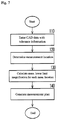
- FIG. 7 is a flowchart illustrating a procedural flow according to an embodiment of the present invention.
- FIG. 8 is a flowchart illustrating a flow for generating the measurement plan according to the embodiment of the present invention.
- FIG. 9 is a perspective view illustrating an example of a standard measurement location
- FIG. 10 is a perspective view illustrating an exemplary group reconstruction range
- FIG. 11 is a perspective view illustrating another example of the group reconstruction range.
- FIG. 12 is a perspective view illustrating yet another example of the group reconstruction range.
- FIG. 5 illustrates an embodiment of a measuring X-ray CT apparatus according to the present invention.
- a measurement plan auto-generation program 44 is newly added to an apparatus configuration similar to FIG. 1 .
- the measurement plan auto-generation program 44 performs auto-generation of a measurement plan (main component of the present invention).
- the measurement plan generated by the measurement plan auto-generation program 44 includes CT scan positions (plural) of a work piece W, measurement locations (plural) of volume data that is generated by the CT scans, and information for a measurement order of the positions and locations.
- the measurement plan as shown in FIG. 6 is generated for the work piece W illustrated in FIGS. 4A and 4B , for example.
- C 1 , C 2 , and C 3 show the CT scan positions respectively and measurement magnification is uniquely determined by the CT scan position. Further, the plan shows that the CT scans are performed in the order of C 1 ⁇ C 2 ⁇ C 3 , and shows locations to be measured with respect to the volume data generated by each CT scan.
- a measurement operator enters CAD data with tolerance information into the measurement plan auto-generation program 44 .
- the CAD data may be entered into the measurement plan auto-generation program 44 from the X-ray CT control program 42 .
- step 120 measurement locations are determined using the tolerance information of the CAD data.
- step 130 using the tolerance information for each measurement location, a minimum magnification required for performing measurement (measurement lower limit magnification) is calculated.
- a required voxel size is found from the tolerance information and the required magnification is calculated from the voxel size.
- VoxelSize k ⁇ precision (4)
- mag DetectorWidth VoxelSize ⁇ VolumeWidth ( 5 )
- step 140 the measurement plan is generated as shown in FIG. 8 .
- the method uses an arbitrary measurement location as a standard; verifies whether other arbitrary measurement locations can each be measured using the same volume data (that is, the same measurement magnification) as the standard; and forms groups that can be measured using the same volume data.
- the measurement locations can be separates into groups, the CT scan positions for generating the volume data for each group are determined and an order is assigned thereto.
- a measurement location that will serve as the standard is selected from among the measurement locations that do not belong to any group. Since there are no groups at the initial stage of generating the measurement plan, the measurement location is selected from all measurement locations.
- a target measurement location positioned on an end is selected.
- the measurement location closest to an X-ray source 12 is defined as the standard reference.
- p4 is closest to the X-ray source 12 and is selected as the standard measurement location.
- the following information is defined for the group that includes the standard measurement location:
- the measurement locations can be measured using the same volume data, and the number of groups ultimately formed is equal to the number of volume data required for the measurement (in other words, the number of CT scan positions).
- the group measurement magnification is a magnification of the work piece included in the corresponding volume data and an initial value thereof is set to the measurement lower limit magnification of the standard measurement location.
- the group reconstruction range shows a range in real space of the corresponding volume data.
- the reconstruction range is handled as a rectangular parallelepiped or a cylinder, however, for ease of calculation, only the cylinder is used in this example.
- a cylinder diameter and a cylinder height are used as values indicating the reconstruction range.
- the initial value is the reconstruction range uniquely obtained by the group measurement magnification.
- DetectorWidth a width of the volume data is defined as VolumeWidth [pixels]
- a height of the volume data is defined as VolumeHeight [pixels]
- the cylinder diameter (Diameter) and the cylinder height (Height) indicating the reconstruction range can be calculated as shown below.
- an arbitrary measurement location other than the standard measurement location is selected from among the measurement locations that do not belong to any group and is defined as the verification measurement location.
- step 230 verification is performed as to whether the verification measurement location can be measured with the same volume data as the standard measurement location. Specifically, verification is performed as to whether the measurement magnification can be matched and included in the same reconstruction range.
- the group measurement magnification can be matched to the larger of the current value and the measurement lower limit magnification of the verification measurement location.
- the group reconstruction range also changes.
- FIG. 10 indicates that, when the standard measurement location is defined as p4 and the verification measurement location is defined as p6, and the measurement lower limit magnification of p4 is ⁇ 10 and the measurement lower limit magnification of p6 is ⁇ 5, p6 is included in the reconstruction range (grouping is possible).
- FIG. 11 indicates that, when the standard measurement location is defined as p4 and the verification measurement location is defined as p5, and the measurement lower limit magnification of p4 is ⁇ 10 and the measurement lower limit magnification of p5 is ⁇ 15, p5 is not included in the reconstruction range (grouping is not possible). When p5 is included, the group measurement magnification is increased to ⁇ 15, and the group reconstruction range becomes smaller accordingly.
- the position of the reconstruction range can be defined as desired, however, due to various restrictions depending on the apparatus configuration, such restrictions must be considered.
- a center of the reconstruction range (cylinder axis) is matched with a rotation center (rotation axis). Therefore, unless there is a special mechanism or the like to change the rotation center, a relative relationship between the rotation axis and each measurement location of the work piece W placed directly on a rotary table 16 is fixed.
- the position of the reconstruction range is restricted due to upper and lower limits on displacement of the rotary table 16 .
- FIG. 12 illustrates a view where the center of the reconstruction range is fixed at the rotation axis of the work piece W when the measurement lower limit magnification of p6 is ⁇ 15.
- the group measurement magnification or the list of the group measurement locations is finalized and the CT scan positions are determined.
- an X position of the rotary table 16 during the CT scan can be determined by the measurement magnification.
- Y/Z positions can be defined as desired within a range where the rotary table 16 can be displaced.
- a center of gravity of all measurement locations included in the group may be set so as to be positioned on the center of the reconstruction range.
- step 250 When determining the CT scan order in step 250 , the processes of step 210 to step 240 are repeated until all the measurement locations are included in any of the groups, after which an execution order is determined for the CT scan positions obtained from each group.
- the order should be set so as to achieve the shortest route for displacing the rotary table 16 to each CT scan position.
- the displacement time of the rotary table 16 is much shorter than the CT scan execution time, and therefore, the displacement time is considered to have no effect on the overall measurement time.
Landscapes
- Physics & Mathematics (AREA)
- General Physics & Mathematics (AREA)
- Health & Medical Sciences (AREA)
- Engineering & Computer Science (AREA)
- Theoretical Computer Science (AREA)
- Biochemistry (AREA)
- Nuclear Medicine, Radiotherapy & Molecular Imaging (AREA)
- Pulmonology (AREA)
- Radiology & Medical Imaging (AREA)
- Life Sciences & Earth Sciences (AREA)
- Chemical & Material Sciences (AREA)
- Analytical Chemistry (AREA)
- General Health & Medical Sciences (AREA)
- Immunology (AREA)
- Pathology (AREA)
- Electromagnetism (AREA)
- Analysing Materials By The Use Of Radiation (AREA)
- Apparatus For Radiation Diagnosis (AREA)
Abstract
Description
[Formula 4]
VoxelSize=k×precision (4)
-
- Group identifier: Gn *n is a number
- Group measurement magnification: Gn_Mag
- Group reconstruction range: Gn_Range
- Group measurement location list: Gn_MeasList
Claims (7)
Applications Claiming Priority (3)
| Application Number | Priority Date | Filing Date | Title |
|---|---|---|---|
| JP2018-051551 | 2018-03-19 | ||
| JPJP2018-051551 | 2018-03-19 | ||
| JP2018051551A JP6983704B2 (en) | 2018-03-19 | 2018-03-19 | Measurement plan generation method and equipment for X-ray CT for measurement |
Publications (2)
| Publication Number | Publication Date |
|---|---|
| US20190287274A1 US20190287274A1 (en) | 2019-09-19 |
| US11037337B2 true US11037337B2 (en) | 2021-06-15 |
Family
ID=67774734
Family Applications (1)
| Application Number | Title | Priority Date | Filing Date |
|---|---|---|---|
| US16/299,513 Active 2039-08-29 US11037337B2 (en) | 2018-03-19 | 2019-03-12 | Method and apparatus for generating measurement plan for measuring X-ray CT |
Country Status (4)
| Country | Link |
|---|---|
| US (1) | US11037337B2 (en) |
| JP (1) | JP6983704B2 (en) |
| CN (1) | CN110286135B (en) |
| DE (1) | DE102019001686A1 (en) |
Cited By (1)
| Publication number | Priority date | Publication date | Assignee | Title |
|---|---|---|---|---|
| US11353410B2 (en) * | 2018-09-14 | 2022-06-07 | Shimadzu Techno-Research, Inc. | Material testing machine and radiation CT device |
Families Citing this family (2)
| Publication number | Priority date | Publication date | Assignee | Title |
|---|---|---|---|---|
| JP7198577B2 (en) * | 2017-11-17 | 2023-01-04 | シスメックス株式会社 | Image analysis method, device, program, and method for manufacturing trained deep learning algorithm |
| JP7137935B2 (en) * | 2018-02-27 | 2022-09-15 | シスメックス株式会社 | Image analysis method, image analysis device, program, method for manufacturing trained deep learning algorithm, and trained deep learning algorithm |
Citations (2)
| Publication number | Priority date | Publication date | Assignee | Title |
|---|---|---|---|---|
| US6574304B1 (en) * | 2002-09-13 | 2003-06-03 | Ge Medical Systems Global Technology Company, Llc | Computer aided acquisition of medical images |
| JP2016205899A (en) | 2015-04-17 | 2016-12-08 | 株式会社ミツトヨ | Control method and device of turntable |
Family Cites Families (14)
| Publication number | Priority date | Publication date | Assignee | Title |
|---|---|---|---|---|
| JPH0692884B2 (en) * | 1990-01-10 | 1994-11-16 | 新日本製鐵株式会社 | X-ray tomography system |
| JP3853620B2 (en) * | 2001-08-21 | 2006-12-06 | 株式会社ミツトヨ | Part program generation device and program for image measurement device |
| EP1380263B1 (en) * | 2002-07-12 | 2007-08-29 | MYCRONA Gesellschaft für innovative Messtechnik mbH | Process and device for measuring the actual position of the structure of an object to be examined |
| DE102005032686A1 (en) * | 2005-07-06 | 2007-01-11 | Carl Zeiss Industrielle Messtechnik Gmbh | Method and device for examining a test object by means of invasive radiation |
| JP5197024B2 (en) * | 2008-01-09 | 2013-05-15 | 株式会社東芝 | Radiotherapy system, radiotherapy support apparatus, and radiotherapy support program |
| TWI467128B (en) * | 2009-07-03 | 2015-01-01 | Koh Young Tech Inc | Method for inspecting measurement object |
| JP5223876B2 (en) * | 2010-03-12 | 2013-06-26 | オムロン株式会社 | X-ray inspection apparatus, X-ray inspection method, X-ray inspection program, and X-ray inspection system |
| JP2014527663A (en) * | 2011-07-29 | 2014-10-16 | ヘキサゴン メトロロジー,インコーポレイテッド | Coordinate measurement system data organization |
| US20140368500A1 (en) * | 2013-06-17 | 2014-12-18 | Hexagon Metrology, Inc. | Method and apparatus of measuring objects using selective imaging |
| US9558569B2 (en) * | 2014-08-12 | 2017-01-31 | Toshiba Medical Systems Corporation | Method and system for substantially reducing cone beam artifacts based upon image domain differentiation in circular computer tomography (CT) |
| JP6763301B2 (en) * | 2014-09-02 | 2020-09-30 | 株式会社ニコン | Inspection equipment, inspection methods, inspection processing programs and structure manufacturing methods |
| WO2016053677A1 (en) * | 2014-09-30 | 2016-04-07 | Hexagon Metrology, Inc. | System and method for measuring an object using x-ray projections |
| DE102016101005A1 (en) * | 2015-02-11 | 2016-08-11 | Werth Messtechnik Gmbh | Device and method for computer tomographic measurement of a workpiece |
| EP3299503B1 (en) | 2016-09-27 | 2021-09-08 | Karl Mayer Rotal Srl | Device and method for feeding a cloth web with a liquor |
-
2018
- 2018-03-19 JP JP2018051551A patent/JP6983704B2/en active Active
-
2019
- 2019-03-08 DE DE102019001686.6A patent/DE102019001686A1/en active Pending
- 2019-03-12 US US16/299,513 patent/US11037337B2/en active Active
- 2019-03-14 CN CN201910192542.6A patent/CN110286135B/en active Active
Patent Citations (3)
| Publication number | Priority date | Publication date | Assignee | Title |
|---|---|---|---|---|
| US6574304B1 (en) * | 2002-09-13 | 2003-06-03 | Ge Medical Systems Global Technology Company, Llc | Computer aided acquisition of medical images |
| JP2016205899A (en) | 2015-04-17 | 2016-12-08 | 株式会社ミツトヨ | Control method and device of turntable |
| US10190996B2 (en) | 2015-04-17 | 2019-01-29 | Mitutoyo Corporation | Method and device for controlling rotary table |
Non-Patent Citations (5)
| Title |
|---|
| Automatic Measurement Program Generation Software: MiCAT Planner, 16019 dated Jan. 2014. |
| U.S. Appl. No. 16/250,167 to Kozo Ariga et al., filed Jan. 17, 2019. |
| U.S. Appl. No. 16/250,201 to Hidemitsu Asano et al., filed Jan. 17, 2019. |
| U.S. Appl. No. 16/291,674 to Sadayuki Matsumiya et al., filed Mar. 4, 2019. |
| U.S. Appl. No. 16/291,699 to Hidemitsu Asano et al., filed Mar. 4, 2019. |
Cited By (1)
| Publication number | Priority date | Publication date | Assignee | Title |
|---|---|---|---|---|
| US11353410B2 (en) * | 2018-09-14 | 2022-06-07 | Shimadzu Techno-Research, Inc. | Material testing machine and radiation CT device |
Also Published As
| Publication number | Publication date |
|---|---|
| DE102019001686A1 (en) | 2019-09-19 |
| JP6983704B2 (en) | 2021-12-17 |
| US20190287274A1 (en) | 2019-09-19 |
| JP2019164008A (en) | 2019-09-26 |
| CN110286135A (en) | 2019-09-27 |
| CN110286135B (en) | 2024-05-07 |
Similar Documents
| Publication | Publication Date | Title |
|---|---|---|
| JP6471151B2 (en) | X-ray inspection system and method for rotating a test object using such an X-ray inspection system | |
| CN108738341B (en) | Spiral CT device | |
| US10545102B2 (en) | Coordinate alignment tool for coordinate measuring device and measuring X-ray CT apparatus | |
| JP5780931B2 (en) | Radiation tomography apparatus, dose calculation method and program | |
| JP5921119B2 (en) | X-ray diagnostic equipment | |
| US11037337B2 (en) | Method and apparatus for generating measurement plan for measuring X-ray CT | |
| JP6711410B2 (en) | Imaging magnification calibration method for radiation tomography apparatus | |
| CN110261416B (en) | X-ray CT apparatus for measurement and tomographic image generation method | |
| JPWO2019008620A1 (en) | X-ray CT system | |
| CN112535490B (en) | X-ray CT apparatus, correction method and apparatus therefor, measurement method and apparatus therefor | |
| JP7154535B2 (en) | Dimensional measurement method using projection image obtained by X-ray CT device | |
| JP5600271B2 (en) | Radiation imaging apparatus and method, and program | |
| JP5060862B2 (en) | Tomography equipment | |
| US20190099151A1 (en) | Systems and methods for image correction in an x-ray device | |
| KR101904788B1 (en) | Computed tomography apparatus | |
| US11262319B2 (en) | Measuring X-ray CT apparatus and production work piece measurement method | |
| JP4818695B2 (en) | Radiographic imaging condition correction device | |
| JP2002209877A (en) | Automatic geometrical quantity measurement of image chain | |
| JP4733484B2 (en) | Computed tomography equipment | |
| JP2022010384A (en) | X-ray CT device | |
| JP2017113081A (en) | X-ray CT apparatus and imaging method | |
| JP7265159B2 (en) | Analysis device and analysis method | |
| JP4416655B2 (en) | Spiral CT system | |
| JP2023130084A (en) | Evaluation device and evaluation method for X-ray CT equipment | |
| JP2025001323A (en) | X-ray ct device and method for controlling x-ray ct device |
Legal Events
| Date | Code | Title | Description |
|---|---|---|---|
| AS | Assignment |
Owner name: MITUTOYO CORPORATION, JAPAN Free format text: ASSIGNMENT OF ASSIGNORS INTEREST;ASSIGNORS:ARIGA, KOZO;CHO, GYOKUBU;ASANO, HIDEMITSU;AND OTHERS;REEL/FRAME:048573/0469 Effective date: 20190311 |
|
| FEPP | Fee payment procedure |
Free format text: ENTITY STATUS SET TO UNDISCOUNTED (ORIGINAL EVENT CODE: BIG.); ENTITY STATUS OF PATENT OWNER: LARGE ENTITY |
|
| STPP | Information on status: patent application and granting procedure in general |
Free format text: DOCKETED NEW CASE - READY FOR EXAMINATION |
|
| STPP | Information on status: patent application and granting procedure in general |
Free format text: NON FINAL ACTION MAILED |
|
| STPP | Information on status: patent application and granting procedure in general |
Free format text: NOTICE OF ALLOWANCE MAILED -- APPLICATION RECEIVED IN OFFICE OF PUBLICATIONS |
|
| STPP | Information on status: patent application and granting procedure in general |
Free format text: PUBLICATIONS -- ISSUE FEE PAYMENT RECEIVED |
|
| STPP | Information on status: patent application and granting procedure in general |
Free format text: PUBLICATIONS -- ISSUE FEE PAYMENT VERIFIED |
|
| STCF | Information on status: patent grant |
Free format text: PATENTED CASE |
|
| MAFP | Maintenance fee payment |
Free format text: PAYMENT OF MAINTENANCE FEE, 4TH YEAR, LARGE ENTITY (ORIGINAL EVENT CODE: M1551); ENTITY STATUS OF PATENT OWNER: LARGE ENTITY Year of fee payment: 4 |