US11036206B2 - Numerical controller - Google Patents
Numerical controller Download PDFInfo
- Publication number
- US11036206B2 US11036206B2 US16/725,053 US201916725053A US11036206B2 US 11036206 B2 US11036206 B2 US 11036206B2 US 201916725053 A US201916725053 A US 201916725053A US 11036206 B2 US11036206 B2 US 11036206B2
- Authority
- US
- United States
- Prior art keywords
- command
- resultant vector
- numerical controller
- synthesis unit
- axis movement
- Prior art date
- Legal status (The legal status is an assumption and is not a legal conclusion. Google has not performed a legal analysis and makes no representation as to the accuracy of the status listed.)
- Active
Links
Images


Classifications
-
- G—PHYSICS
- G05—CONTROLLING; REGULATING
- G05B—CONTROL OR REGULATING SYSTEMS IN GENERAL; FUNCTIONAL ELEMENTS OF SUCH SYSTEMS; MONITORING OR TESTING ARRANGEMENTS FOR SUCH SYSTEMS OR ELEMENTS
- G05B19/00—Program-control systems
- G05B19/02—Program-control systems electric
- G05B19/18—Numerical control [NC], i.e. automatically operating machines, in particular machine tools, e.g. in a manufacturing environment, so as to execute positioning, movement or co-ordinated operations by means of program data in numerical form
- G05B19/41—Numerical control [NC], i.e. automatically operating machines, in particular machine tools, e.g. in a manufacturing environment, so as to execute positioning, movement or co-ordinated operations by means of program data in numerical form characterised by interpolation, e.g. the computation of intermediate points between programmed end points to define the path to be followed and the rate of travel along that path
- G05B19/4103—Digital interpolation
-
- G—PHYSICS
- G05—CONTROLLING; REGULATING
- G05B—CONTROL OR REGULATING SYSTEMS IN GENERAL; FUNCTIONAL ELEMENTS OF SUCH SYSTEMS; MONITORING OR TESTING ARRANGEMENTS FOR SUCH SYSTEMS OR ELEMENTS
- G05B19/00—Program-control systems
- G05B19/02—Program-control systems electric
- G05B19/18—Numerical control [NC], i.e. automatically operating machines, in particular machine tools, e.g. in a manufacturing environment, so as to execute positioning, movement or co-ordinated operations by means of program data in numerical form
- G05B19/4155—Numerical control [NC], i.e. automatically operating machines, in particular machine tools, e.g. in a manufacturing environment, so as to execute positioning, movement or co-ordinated operations by means of program data in numerical form characterised by program execution, i.e. part program or machine function execution, e.g. selection of a program
-
- G—PHYSICS
- G05—CONTROLLING; REGULATING
- G05B—CONTROL OR REGULATING SYSTEMS IN GENERAL; FUNCTIONAL ELEMENTS OF SUCH SYSTEMS; MONITORING OR TESTING ARRANGEMENTS FOR SUCH SYSTEMS OR ELEMENTS
- G05B19/00—Program-control systems
- G05B19/02—Program-control systems electric
- G05B19/18—Numerical control [NC], i.e. automatically operating machines, in particular machine tools, e.g. in a manufacturing environment, so as to execute positioning, movement or co-ordinated operations by means of program data in numerical form
- G05B19/408—Numerical control [NC], i.e. automatically operating machines, in particular machine tools, e.g. in a manufacturing environment, so as to execute positioning, movement or co-ordinated operations by means of program data in numerical form characterised by data handling or data format, e.g. reading, buffering or conversion of data
-
- G—PHYSICS
- G05—CONTROLLING; REGULATING
- G05B—CONTROL OR REGULATING SYSTEMS IN GENERAL; FUNCTIONAL ELEMENTS OF SUCH SYSTEMS; MONITORING OR TESTING ARRANGEMENTS FOR SUCH SYSTEMS OR ELEMENTS
- G05B19/00—Program-control systems
- G05B19/02—Program-control systems electric
- G05B19/18—Numerical control [NC], i.e. automatically operating machines, in particular machine tools, e.g. in a manufacturing environment, so as to execute positioning, movement or co-ordinated operations by means of program data in numerical form
- G05B19/182—Numerical control [NC], i.e. automatically operating machines, in particular machine tools, e.g. in a manufacturing environment, so as to execute positioning, movement or co-ordinated operations by means of program data in numerical form characterised by the machine tool function, e.g. thread cutting, cam making, tool direction control
-
- G—PHYSICS
- G05—CONTROLLING; REGULATING
- G05B—CONTROL OR REGULATING SYSTEMS IN GENERAL; FUNCTIONAL ELEMENTS OF SUCH SYSTEMS; MONITORING OR TESTING ARRANGEMENTS FOR SUCH SYSTEMS OR ELEMENTS
- G05B19/00—Program-control systems
- G05B19/02—Program-control systems electric
- G05B19/18—Numerical control [NC], i.e. automatically operating machines, in particular machine tools, e.g. in a manufacturing environment, so as to execute positioning, movement or co-ordinated operations by means of program data in numerical form
- G05B19/416—Numerical control [NC], i.e. automatically operating machines, in particular machine tools, e.g. in a manufacturing environment, so as to execute positioning, movement or co-ordinated operations by means of program data in numerical form characterised by control of velocity, acceleration or deceleration
- G05B19/4163—Adaptive control of feed or cutting velocity
-
- G—PHYSICS
- G05—CONTROLLING; REGULATING
- G05B—CONTROL OR REGULATING SYSTEMS IN GENERAL; FUNCTIONAL ELEMENTS OF SUCH SYSTEMS; MONITORING OR TESTING ARRANGEMENTS FOR SUCH SYSTEMS OR ELEMENTS
- G05B2219/00—Program-control systems
- G05B2219/30—Nc systems
- G05B2219/33—Director till display
- G05B2219/33271—Convert workpiece to machine coordinates
-
- G—PHYSICS
- G05—CONTROLLING; REGULATING
- G05B—CONTROL OR REGULATING SYSTEMS IN GENERAL; FUNCTIONAL ELEMENTS OF SUCH SYSTEMS; MONITORING OR TESTING ARRANGEMENTS FOR SUCH SYSTEMS OR ELEMENTS
- G05B2219/00—Program-control systems
- G05B2219/30—Nc systems
- G05B2219/34—Director, elements to supervisory
- G05B2219/34095—Look ahead segment calculation
Definitions
- the present disclosure relates to a numerical controller, and particularly relates to a numerical controller that realizes efficient performance of a synthesis processing for blocks in a continuous axis control command.
- NC program In a machining program (NC program) executed by a numerical controller, one line segment or arc movement command is normally described for each block. Therefore, when a machining path including a plurality of line segments or arcs is commanded, it is necessary to describe the axis movement command continuously over a plurality of blocks (see FIG. 1 ).
- the numerical controller normally reads command blocks described in the NC program successively from a head to analyze a program, generates block information, performs interpolation processing based on the block information, and creates a distribution pulse of each axis.
- the numerical controller needs to continuously create and output the distribution pulse without interruption. For this reason, the numerical controller needs to complete creation of block information necessary for interpolation prior to interpolation processing. Therefore, the numerical controller normally starts reading each block of the NC program before a command described in the block is executed, and analyzes all commands included in the NC program, which is referred to as prefetch processing (see FIG. 2 ).
- a numerical controller is a numerical controller for generating block information of a path by analyzing an axis movement command described in a machining program, the numerical controller including a command analysis unit for analyzing the machining program in which the axis movement command for a plurality of sections is described in one block in a reading processing for the one block to specify a plurality of coordinate values, a command synthesis unit for generating a plurality of direction vectors constituting the path based on the plurality of coordinate values and generating a resultant vector obtained by adding the direction vectors, and a block information generation unit for generating the block information based on the resultant vector.
- the command synthesis unit generates the resultant vector when a tolerance related to the resultant vector is less than a predetermined allowable value.
- the command synthesis unit generates the resultant vector when a length of the resultant vector is less than a predetermined allowable value.
- the command synthesis unit generates the resultant vector when a plurality of the axis movement commands includes the same feed speed or main axis rotating speed.
- the command synthesis unit generates the resultant vector when a plurality of the axis movement commands includes a specific and the same G code, T code, or mode command.
- FIG. 1 is a diagram illustrating an example of a conventional machining program
- FIG. 2 is a diagram illustrating an example of conventional prefetch processing
- FIG. 3 is a diagram illustrating a hardware configuration example of a numerical controller
- FIG. 4 is a diagram illustrating an example of a conventional axis movement command
- FIG. 5 is a diagram illustrating an example of an axis movement command in the present embodiment
- FIG. 6 is a diagram illustrating an example of an axis movement command in the present embodiment
- FIG. 7 is a diagram illustrating an example of an axis movement command in the present embodiment
- FIG. 8 is a diagram illustrating an example of an axis movement command in the present embodiment
- FIG. 9 is a diagram illustrating an example of an axis movement command in the present embodiment.
- FIG. 10 is a diagram illustrating an example of an axis movement command in the present embodiment
- FIG. 11 is a diagram illustrating an operation example of a conventional numerical controller
- FIG. 12 is a diagram illustrating an operation example of the numerical controller
- FIG. 13 is a diagram illustrating an operation example of the numerical controller
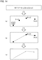
- FIG. 14 is a diagram illustrating an operation example of the numerical controller
- FIG. 15 is a diagram illustrating a functional configuration example of the numerical controller
- FIG. 16 is a diagram illustrating an example of a machining path synthesis processing by a command synthesis unit
- FIG. 17 is a diagram illustrating an example of the machining path synthesis processing by the command synthesis unit
- FIG. 18 is a diagram illustrating an example of the machining path synthesis processing by the command synthesis unit.
- FIG. 19 is a diagram illustrating an example of the machining path synthesis processing by the command synthesis unit.
- FIG. 3 is a schematic hardware configuration diagram illustrating a numerical controller 1 according to an embodiment.
- the numerical controller 1 is a device that controls an industrial machine including a machine tool.
- the numerical controller 1 includes a central processing unit (CPU) 11 , a read only memory (ROM) 12 , a random access memory (RAM) 13 , a nonvolatile memory 14 , a bus 10 , an axis control circuit 16 , a servo amplifier 17 , and an interface 18 .
- a servomotor 50 and an input/output device 60 are connected to the numerical controller 1 .
- the CPU 11 is a processor that controls the numerical controller 1 as a whole.
- the CPU 11 reads a system program stored in the ROM 12 via the bus 10 .
- the CPU 11 controls the entire numerical controller 1 according to the system program.
- the ROM 12 stores in advance a system program for executing various controls of a machine.
- the RAM 13 temporarily stores calculation data or display data, and data, a program, or the like input by an operator via the input/output device 60 .
- the nonvolatile memory 14 is backed up by a battery (not illustrated).
- the nonvolatile memory 14 maintains a storage state even when a power source of the numerical controller 1 is turned off.
- the nonvolatile memory 14 stores data, a program, etc. input from the input/output device 60 .
- the program and data stored in the nonvolatile memory 14 may be loaded in the RAM 13 during execution and use.
- the axis control circuit 16 controls an operating axis of the machine.
- the axis control circuit 16 receives a movement command amount of the axis output by the CPU 11 and outputs a movement command of the operating axis to the servo amplifier 17 .
- the servo amplifier 17 receives the axis movement command output by the axis control circuit 16 and drives the servomotor 50 .
- the servomotor 50 is driven by the servo amplifier 17 to move the operating axis of the machine.
- a spindle is moved by the servomotor 50 .
- the servomotor 50 has a position/speed detector.
- the position/speed detector outputs a position/speed feedback signal. This position/speed feedback signal is fed back to the axis control circuit 16 so that position/speed feedback control is performed.
- FIG. 3 only one set of an axis control circuit 16 , a servo amplifier 17 , and a servomotor 50 is illustrated. However, in practice, the set is prepared for each axis provided in the machine to be controlled.
- the input/output device 60 is a data input/output device including a display, a hardware key, etc.
- the input/output device 60 is an MDI unit or an operation panel.
- the input/output device 60 displays information received from the CPU 11 via the interface 18 on a display.
- the input/output device 60 passes a command, data, etc. input from a hardware key, etc. to the CPU 11 via the interface 18 .
- FIG. 15 is a block diagram illustrating an outline of a functional configuration of the numerical controller 1 .
- the numerical controller 1 includes a command analysis unit 101 , a command synthesis unit 102 , and a block information generation unit 103 .
- the command analysis unit 101 reads and analyzes a machining program including an axis movement command that can define line segments of a plurality of sections using a command of one block.
- the command analysis unit 101 specifies all coordinate points as movement destinations based on an analysis result of the machining program.
- the command synthesis unit 102 performs a processing of synthesizing vectors constituting a machining path.
- the block information generation unit 103 generates block information of the machining path indicated by a vector synthesized by the command synthesis unit 102 .
- FIG. 4 is a diagram illustrating an example of a conventional axis movement command.
- the axis movement command includes a combination of an address indicated by alphabets (G, X, Y, Z, etc.) and a command value indicated by numbers.
- Commands such as G91 and G00 are referred to as G codes.
- G code causes the numerical controller 1 to execute a preparation function for performing machining.
- a command such as F4000. is a movement command.
- a numerical value of the movement command indicates a feed speed.
- Each command such as X1.5, Y2., and Z-95 designates a coordinate value or a movement amount of an X-axis, a Y-axis, and a Z-axis.
- a conventional description method for the axis movement command in principle, only one line segment can be expressed by one block (one line of the machining program).
- axis movement command of the present embodiment content corresponding to a command for a plurality of conventional blocks can be described using a command of one block.
- This axis movement command has the following features.
- command values (coordinate values, movement amounts, etc.) corresponding to each address.
- a correlation between an address and a command value is described according to a predetermined rule.
- the rule is not particularly limited. For example, the following rules are present.
- a correlation between an address and a plurality of command values is defined by a plurality of types of predetermined delimiters.
- a set of command values for each section is defined by “[” and “]” (square brackets).
- “,” (comma) indicates a delimiter between command values of each address. That is, [x1, y1, z1] is a command value group that defines a line segment in a first section, x1 is an X-axis command value, y1 is a Y-axis command value, and z1 is a Z-axis command value.
- [x2, y2, z2] is a command value group that defines a line segment in a second section, and [x3, y3, z3] is a command value group that defines a line segment in a third section.
- FIG. 6 is an axis movement command described according to a format illustrated in FIG. 5 .
- Content described in FIG. 6 is equivalent to the axis movement command according to a conventional description method illustrated in FIG. 4 .
- Axis movement commands described from a second line to a third line in FIG. 4 are integrated in a second line in FIG. 6 .
- axis movement commands described from a fourth line to a sixth line in FIG. 4 are integrated in a third line in FIG. 6 .
- Correlations between addresses and a plurality of command values are defined by predetermined delimiters and numerical order.
- a command value group x1, y1, and z defining line segments in a first section (x1 is a command value on the X-axis, y1 is a command value on the Y-axis, and z1 is a command value on the Z-axis), a command value group x2, y2, and z2 defining line segments in a second section (x2 is a command value on the X-axis, y2 is a command value on the Y-axis, and z2 is a command value on the Z-axis), . . .
- a command value group xn, yn, and zn defining line segments in an n-th section can also be collectively described for each section as follows.
- X, Y, Z x1, y1, z1, x2, y2, z2, . . . , xn, yn, zn
- command value groups can also be collectively described for each address as follows.
- X, Y, Z x1, x2, . . . , xn, y1, y2, . . . , yn, z1, z2, . . . , zn
- FIG. 7 (second line and fourth line) is an example in which the following axis movement command A is rewritten using an array type variable.
- the axis movement command A is described according to a format shown in FIG. 5 .
- a right side of the axis movement command A is stored in advance in an array type variable (second line), and the command is described in a form referring to the variable (fourth line).
- FIG. 8 (third line) is an example in which the following axis movement command B is rewritten using an external file reference.
- the axis movement command B is described according to a format shown in FIG. 5 .
- content corresponding to a right side of the axis movement command B is described in advance in an external file (PATH1.csv), and the command is described in a form referring to content of the file (third line).
- N22 G01 X, Y, Z [0, 0, 0], [1, 1, 1], [2, 2, 2], . . . ;
- FIG. 9 (third line) is an example in which the following axis movement command C is rewritten using an external file reference.
- the axis movement command C is described according to a format shown in FIG. 5 .
- content corresponding to a right side of the axis movement command C is described in advance in an external file (CAM_DATA.NC), and the command is described in a form referring to content of the file (third line).
- a file format of the external file or a format of the axis movement command may be any file format or format as long as a correlation with the command content before rewriting is maintained. However, it is necessary that the command analysis unit 101 can recognize the correlation and restore the command content before rewriting.
- FIG. 10 (e) A command can also be described in a form referring to data set.
- FIG. 10 (second line) is an example in which the following axis movement command D is rewritten into a format referring to a data set.
- content of a part following N21 of the axis movement command D is stored in advance in a data set (for example, a structure) (CYCLE1), and the command is described in a form referring to content of the data set (second line).
- a data set for example, a structure
- the format of the data set may be any format as long as a correlation with the command content before rewriting is maintained. However, it is necessary that the command analysis unit 101 can recognize the correlation and restore the command content before rewriting. Even when a data set is used, an address is described only once in the data set.
- command description may be omitted.
- first line when the Z-axis does not move (first line), only the commands related to the X-axis and the Y-axis are described, and no command is described for the Z-axis.
- X-axis does not move (third line)
- third line when the X-axis does not move (third line), only commands related to the Y-axis and the Z-axis are described in this block, and no command is described for the X-axis.
- a command value (numerical value) may be omitted while defining an axis address.
- the axis movement command F can be described as follows.
- This command is obtained by integrating and describing an axis movement command G, which has been described as the follows in a conventional description method, into one line.
- the processing of synthesizing the vectors constituting the machining path will be described in detail with reference to FIG. 16 to FIG. 19 .
- machining is performed according to a machining path formed by successively connecting coordinate points specified by the command analysis unit 101 .
- path synthesis processing when the operator, etc. desires to check a rough machining path or machining flow during test operation, etc., several direction vectors constituting the machining path are synthesized (path synthesis processing), and a simplified machining path is generated. In this way, the operation is performed based on the simplified machining path.
- the command synthesis unit 102 determines whether to execute the path synthesis processing based on tolerance.
- the command synthesis unit 102 determines whether to execute the path synthesis processing based on a path length.
- the tolerance Tr refers to a distance between a connection point of two direction vectors and a resultant vector when the resultant vector is generated by synthesizing the two direction vectors constituting the machining path. For example, when a direction vector from a start point to coordinates [x1, y1] and a direction vector from the coordinates [x1, y1] to coordinates [x2, y2] are synthesized to generate a resultant vector from the start point to the coordinates [x2, y2], a distance from the coordinates [x1, y1] to the resultant vector corresponds to the tolerance Tr (see FIG. 17 ).
- a resultant vector is generated when the tolerance Tr is less than a predetermined threshold value.
- the tolerance Tr is equal to or greater than the predetermined threshold value, no resultant vector is generated. Due to this limitation, a simplified machining path is generated without greatly deviating from an original machining path.
- FIG. 16 is a flowchart for description of the path synthesis processing performed based on the tolerance.
- the command synthesis unit 102 reads a coordinate point having an earliest machining order among the plurality of coordinate points specified by the command analysis unit 101 (SA 101 ).
- the command synthesis unit 102 generates a direction vector to the read coordinate point using a current position (start point) as an origin (SA 102 ).
- the command synthesis unit 102 stores the generated direction vector as a first resultant vector (SA 103 to SA 104 ).
- the command analysis unit 101 specifies a plurality of coordinate points based on the following axis movement command H.
- the command synthesis unit 102 first reads the coordinates [x1, y1] among these coordinates, and generates a direction vector from the start point, that is, the current position to the coordinates [x1, y1]. In addition, the command synthesis unit 102 stores the generated direction vector as a first resultant vector.
- the command synthesis unit 102 reads a coordinate point of a subsequent machining order using the coordinate point read in SA 101 as a new origin (SA 101 ), and generates a direction vector from the origin to the read coordinate point (SA 102 ).
- the command synthesis unit 102 reads the coordinates [x2, y2] and generates a direction vector from the origin [x1, y1] to the coordinates [x2, y2].
- the command synthesis unit 102 adds the generated direction vector to the first resultant vector to generate a new resultant vector (SA 103 to SA 107 ).
- the first resultant vector from the start point to the coordinates [x1, y1] and the direction vector from the coordinates [x1, y1] to the coordinates [x2, y2] are added to generate a new resultant vector from the start point to the coordinates [x2, y2].
- the command synthesis unit 102 calculates the tolerance Tr related to the synthesis processing, that is, a distance between a connection point of two vectors corresponding to basis of the new resultant vector and the new resultant vector (SA 108 ).
- a connection point between two vectors corresponds to [x1, y1] and the direction vector from the coordinates [x1, y1] to the coordinates [x2, y2]
- the command synthesis unit 102 calculates the distance Tr between a point indicated by the coordinates [x1, y1] and the new resultant vector.
- the command synthesis unit 102 compares the tolerance Tr with an allowable value (threshold value) (SA 109 ). When the tolerance Tr is less than a predetermined allowable value, the command synthesis unit 102 repeats processing of SA 101 to SA 108 , further reads a new coordinate point, and generates a new resultant vector.
- threshold value an allowable value
- the command synthesis unit 102 reads a new coordinate point [x3, y3], and generates a direction vector from the previously read coordinate point [x2, y2] to the newly read coordinate point [x3, y3].
- the command synthesis unit 102 adds the newly generated direction vector and the previously generated resultant vector to generate a new resultant vector from the start point to the coordinates [x3, y3].
- the command synthesis unit 102 discards the currently generated resultant vector and transfers the previously generated resultant vector to the block information generation unit 103 . In this way, a path indicated by the previously generated resultant vector is adopted as a simple machining path. Further, the command synthesis unit 102 sets the previously read coordinate value as an origin, and sets the currently generated direction vector as the first resultant vector (SA 111 to SA 113 ). Hereinafter, the same processing is repeated for the plurality of coordinate points specified by the command analysis unit 101 .
- the command synthesis unit 102 discards the currently generated resultant vector (a new resultant vector from the start point to the coordinates [x3, y3]). In addition, the command synthesis unit 102 determines a path indicated by the previously generated resultant vector (resultant vector from the start point to the coordinates [x2, y2]) as the machining path ((d) of FIG. 17 ).
- a path length refers to a length of a resultant vector when the resultant vector is generated by synthesizing two direction vectors constituting a machining path. For example, a direction vector from the start point to the coordinates [x1, y1] and a direction vector from the coordinates [x1, y1] to the coordinates [x2, y2] are synthesized to generate a resultant vector from the start point to the coordinates [x2, y2]. In this case, a distance from the start point to the coordinates [x2, y2] is the path length (see FIG. 19 ).
- the resultant vector is generated when the path length is less than a predetermined threshold value.
- the path length is greater than or equal to the predetermined threshold, no resultant vector is generated. Due to this limitation, a simplified machining path is generated without greatly deviating from an original machining path.
- FIG. 18 is a flowchart for description of a path synthesis processing performed based on the path length.
- the command synthesis unit 102 reads a coordinate point having an earliest machining order among the plurality of coordinate points specified by the command analysis unit 101 (SB 101 ).
- the command synthesis unit 102 generates a direction vector to the read coordinate point using a current position (start point) as an origin (SB 102 ).
- the command synthesis unit 102 stores the generated direction vector as the first resultant vector (SB 103 to SB 104 ).
- the command analysis unit 101 specifies a plurality of coordinate points based on the following axis movement command I.
- the command synthesis unit 102 first reads the coordinates [x1, y1] among these coordinates, and generates a direction vector from the start point, that is, the current position to the coordinates [x1, y1]. In addition, the command synthesis unit 102 stores the generated direction vector as a first resultant vector.
- the command synthesis unit 102 reads a coordinate point of a subsequent machining order using the coordinate point read in SB 101 as a new origin (SB 101 ), and generates a direction vector from the origin to the read coordinate point (SB 102 ).
- the command synthesis unit 102 reads the coordinates [x2, y2] and generates a direction vector from the origin [x1, y1] to the coordinates [x2, y2].
- the command synthesis unit 102 adds the generated direction vector to the first resultant vector to generate a new resultant vector (SB 103 to SB 107 ).
- the command synthesis unit 102 adds the first resultant vector from the start point to the coordinates [x1, y1] and the direction vector from the coordinates [x1, y1] to the coordinates [x2, y2] to generate a new resultant vector from the start point to the coordinates [x2, y2].
- the command synthesis unit 102 calculates a path length of the new resultant vector generated by this synthesis processing (SB 108 ).
- the command synthesis unit 102 calculates the length of the new resultant vector (new resultant vector from the start point to the coordinates [x2, y2]).
- the command synthesis unit 102 compares the path length with an allowable value (threshold value) (SB 109 ). When the path length is less than a predetermined allowable value, the command synthesis unit 102 repeats processing of SB 101 to SB 108 , further reads a new coordinate point, and generates a new resultant vector.
- the command synthesis unit 102 reads a new coordinate point [x3, y3], and generates a direction vector from the previously read coordinate point [x2, y2] to the newly read coordinate point [x3, y3]. In addition, the command synthesis unit 102 adds this direction vector and the previously generated resultant vector to generate a new resultant vector from the start point to the coordinates [x3, y3].
- the command synthesis unit 102 discards the currently generated resultant vector and transfers the previously generated resultant vector to the block information generation unit 103 . In this way, a path indicated by the previously generated resultant vector is adopted as a simple machining path. Further, the command synthesis unit 102 sets the previously read coordinate value as an origin, and sets the currently generated direction vector as a new resultant vector (SB 111 to SB 113 ). Hereinafter, the same processing is repeated for the plurality of coordinate points specified by the command analysis unit 101 .
- the command synthesis unit 102 discards the currently generated resultant vector (a new resultant vector from the start point to the coordinates [x3, y3]). In addition, the command synthesis unit 102 determines a path indicated by the previously generated resultant vector (resultant vector from the start point to the coordinates [x2, y2]) as the machining path ((d) of FIG. 19 ).
- tolerance and path length are used as an index for determining whether the vector synthesis processing can be executed.
- similar determination can be made using various indices without being limited to these indices. Some examples are shown below.
- the command synthesis unit 102 can synthesize a plurality of vectors constituting the machining path set to the same feed speed. For example, a case where the command analysis unit 101 reads an axis movement command J of the following machining program is considered.
- the command synthesis unit 102 generates one resultant vector by synthesizing a plurality of vectors constituting a continuous machining path for which the same feed speed F is commanded.
- a path indicated by the resultant vector is the machining path.
- a path indicated by a vector from the current position (start point) to the coordinates [x3, y3] is a machining path after synthesis, which corresponds to the same result as that in a case where the following axis movement command K is executed.
- the command synthesis unit 102 can synthesize a plurality of vectors indicating machining paths having the same spindle rotating speed (command S). Since specific processing content is the same as that of the vector synthesis based on the above-mentioned feed speed, a description thereof is omitted.
- the command synthesis unit 102 can synthesize vectors constituting a plurality of paths having the same G code command. In this instance, only vectors constituting a machining path commanded by a specific G code can also be set as a target for synthesis. For example, the command synthesis unit 102 can set only vectors constituting a machining path commanded by a G code “G01” as a target for synthesis. In this case, vectors constituting a plurality of continuous machining paths for which the G code “G01” is commanded are synthesized. On the other hand, vectors constituting a machining path for which another G code interpolation command such as “G02” is given are not synthesized.
- the command synthesis unit 102 can synthesize a plurality of vectors constituting a machining path having the same T code (tool exchange) command, that is, a machining path machined by the same tool. In addition, it is possible to synthesize a plurality of vectors constituting a machining path having the same mode command indicating a machining state, etc. Since specific processing content is the same as that of the vector synthesis processing based on the above-mentioned G code, a description thereof is omitted.
- FIG. 11 is a diagram illustrating an operation of a conventional numerical controller.
- the conventional numerical controller reads one block of the machining program (S 1 ) and analyzes the read one block of a program (S 2 ). Then, block information of one line segment described in the block is generated (S 3 ).
- the numerical controller performs an ancillary processing such as modal switching or determination of various signals for each block (S 4 ). The numerical controller repeats processing of S 1 to S 4 for all blocks of the machining program.
- FIG. 12 is a diagram illustrating an operation of the numerical controller 1 according to the present embodiment.
- the command analysis unit 101 of the numerical controller 1 reads one block of the machining program (S 101 ) and analyzes the read one block of a program (S 102 ).
- the command analysis unit 101 analyzes the block and extracts a plurality of coordinate values or movement amounts described in the block (see (b) of FIG. 13 ).
- the command synthesis unit 102 When the command analysis unit 101 outputs a plurality of coordinate values (S 103 ), the command synthesis unit 102 generates a machining path based on the coordinate values (see (a) of FIG. 14 ). In this instance, some of a plurality of direction vectors constituting the original machining path are synthesized and replaced with a simplified machining path (S 104 ) (see (b) and (c) of FIG. 14 ).
- the block information generation unit 103 generates block information of the machining path synthesized by the command synthesis unit 102 (S 105 ). Thereafter, an ancillary processing such as modal switching or determination of various signals is performed (S 106 ), and processing of this block is ended.
- the numerical controller 1 repeats processing of S 101 to S 106 for all blocks of the machining program.
- the numerical controller 1 can synthesize a plurality of blocks without determining whether a read block is a linear interpolation block each time a program of one block is read and without depending on the maximum number of blocks for prefetch processing.
Landscapes
- Engineering & Computer Science (AREA)
- Human Computer Interaction (AREA)
- Manufacturing & Machinery (AREA)
- Physics & Mathematics (AREA)
- General Physics & Mathematics (AREA)
- Automation & Control Theory (AREA)
- Computing Systems (AREA)
- Theoretical Computer Science (AREA)
- Numerical Control (AREA)
Abstract
Description
X, Y, Z =x1, y1, z1, x2, y2, z2, . . . , xn, yn, zn
X, Y, Z=x1, x2, . . . , xn, y1, y2, . . . , yn, z1, z2, . . . , zn
-
- Feed speed
-
- Spindle rotating speed
-
- G code
-
- T code, mode command, etc.
Claims (5)
Applications Claiming Priority (3)
| Application Number | Priority Date | Filing Date | Title |
|---|---|---|---|
| JP2019-000836 | 2019-01-07 | ||
| JP2019000836A JP6871280B2 (en) | 2019-01-07 | 2019-01-07 | Numerical control device |
| JPJP2019-000836 | 2019-01-07 |
Publications (2)
| Publication Number | Publication Date |
|---|---|
| US20200218234A1 US20200218234A1 (en) | 2020-07-09 |
| US11036206B2 true US11036206B2 (en) | 2021-06-15 |
Family
ID=71402498
Family Applications (1)
| Application Number | Title | Priority Date | Filing Date |
|---|---|---|---|
| US16/725,053 Active US11036206B2 (en) | 2019-01-07 | 2019-12-23 | Numerical controller |
Country Status (4)
| Country | Link |
|---|---|
| US (1) | US11036206B2 (en) |
| JP (1) | JP6871280B2 (en) |
| CN (1) | CN111413927B (en) |
| DE (1) | DE102019009083A1 (en) |
Families Citing this family (1)
| Publication number | Priority date | Publication date | Assignee | Title |
|---|---|---|---|---|
| TWI757926B (en) | 2020-10-22 | 2022-03-11 | 財團法人工業技術研究院 | Machine tool numerical controller software dynamic generating apparatus and method for the same |
Citations (4)
| Publication number | Priority date | Publication date | Assignee | Title |
|---|---|---|---|---|
| JPH09198116A (en) * | 1996-01-17 | 1997-07-31 | Yaskawa Electric Corp | Numerical control device block data processing method |
| JPH09288509A (en) | 1996-04-22 | 1997-11-04 | Yaskawa Electric Corp | Numerical control device block data processing method |
| US20120016514A1 (en) * | 2009-06-03 | 2012-01-19 | Mitsubishi Electric Corporation | Numerical control apparatus and production system |
| US20150227131A1 (en) * | 2014-02-13 | 2015-08-13 | Fanuc Corporation | Numerical controller having command path compression function |
Family Cites Families (11)
| Publication number | Priority date | Publication date | Assignee | Title |
|---|---|---|---|---|
| US4891763A (en) * | 1986-04-24 | 1990-01-02 | Brother Kogyo Kabushiki Kaisha | NC program editing and programming device |
| JP6012560B2 (en) * | 2013-08-07 | 2016-10-25 | 三菱電機株式会社 | Numerical controller |
| WO2015097886A1 (en) * | 2013-12-27 | 2015-07-02 | 株式会社牧野フライス製作所 | Machining-information management device and tool-path generation device |
| WO2015140906A1 (en) * | 2014-03-17 | 2015-09-24 | 三菱電機株式会社 | Numerical control device |
| JP6312725B2 (en) * | 2016-02-23 | 2018-04-18 | ファナック株式会社 | Numerical control device with taper angle correction function in taper machining in skiving |
| JP6363643B2 (en) * | 2016-03-04 | 2018-07-25 | ファナック株式会社 | Numerical control device that can increase the number of analysis digits of program command |
| CN105945946B (en) * | 2016-05-23 | 2018-02-02 | 东莞理工学院 | A kind of six axis robot motion control method based on G code programming |
| JP6441262B2 (en) * | 2016-06-24 | 2018-12-19 | ファナック株式会社 | Machining program editing apparatus, method, and editing program |
| JP6426662B2 (en) * | 2016-06-30 | 2018-11-21 | ファナック株式会社 | Numerical control device for skiving control |
| JP6407947B2 (en) * | 2016-12-16 | 2018-10-17 | ファナック株式会社 | Numerical controller |
| JP6538754B2 (en) * | 2017-05-24 | 2019-07-03 | ファナック株式会社 | Numerical control device |
-
2019
- 2019-01-07 JP JP2019000836A patent/JP6871280B2/en active Active
- 2019-12-23 US US16/725,053 patent/US11036206B2/en active Active
- 2019-12-30 DE DE102019009083.7A patent/DE102019009083A1/en active Pending
-
2020
- 2020-01-07 CN CN202010013809.3A patent/CN111413927B/en active Active
Patent Citations (4)
| Publication number | Priority date | Publication date | Assignee | Title |
|---|---|---|---|---|
| JPH09198116A (en) * | 1996-01-17 | 1997-07-31 | Yaskawa Electric Corp | Numerical control device block data processing method |
| JPH09288509A (en) | 1996-04-22 | 1997-11-04 | Yaskawa Electric Corp | Numerical control device block data processing method |
| US20120016514A1 (en) * | 2009-06-03 | 2012-01-19 | Mitsubishi Electric Corporation | Numerical control apparatus and production system |
| US20150227131A1 (en) * | 2014-02-13 | 2015-08-13 | Fanuc Corporation | Numerical controller having command path compression function |
Also Published As
| Publication number | Publication date |
|---|---|
| DE102019009083A1 (en) | 2020-07-23 |
| JP2020109599A (en) | 2020-07-16 |
| JP6871280B2 (en) | 2021-05-12 |
| CN111413927B (en) | 2024-02-02 |
| CN111413927A (en) | 2020-07-14 |
| US20200218234A1 (en) | 2020-07-09 |
Similar Documents
| Publication | Publication Date | Title |
|---|---|---|
| EP1869531B1 (en) | Method of tolerance-based trajectory planning | |
| US4587608A (en) | Method of automatically creating numerical control data in one of a plurality of data formats | |
| US10386811B2 (en) | Numerical controller | |
| Bosetti et al. | Feed-rate and trajectory optimization for CNC machine tools | |
| WO2014155723A1 (en) | Numerical control device | |
| US10048675B2 (en) | Numerical controller performing 3-dimensional interference check corresponding to feedrate change | |
| JP2009545826A (en) | System control of machine tools | |
| US20160062336A1 (en) | Numerical controller for facilitating adjustment of machining motion | |
| US11036206B2 (en) | Numerical controller | |
| JP3451594B2 (en) | Storage unit access control method and numerical control device in numerical control device | |
| JPH06274228A (en) | Numerical control device | |
| JP2007094936A (en) | Numerical value controller | |
| US11194313B2 (en) | Numerical controller | |
| US11320800B2 (en) | Optimization device | |
| US11086291B2 (en) | Method for operating a numerically controlled production system, and production system for same | |
| US9964943B2 (en) | Numerical controller operating based on tabular data | |
| JP2021067997A (en) | Numerical control device | |
| JP6219866B2 (en) | Numerical control device with display function and display program | |
| JP4560191B2 (en) | Numerical controller | |
| WO2023276121A9 (en) | Numerical control device | |
| WO2025220121A1 (en) | Coordinate value calculating device and computer-readable storage medium | |
| KR0136142B1 (en) | The method of graphic simulation using numerical control apparatus | |
| JP2002312006A (en) | Control device and control system | |
| WO2025220123A1 (en) | Coordinate value calculating device and computer-readable storage medium | |
| WO2024084706A1 (en) | Machining instruction correction device and machining instruction correction method |
Legal Events
| Date | Code | Title | Description |
|---|---|---|---|
| FEPP | Fee payment procedure |
Free format text: ENTITY STATUS SET TO UNDISCOUNTED (ORIGINAL EVENT CODE: BIG.); ENTITY STATUS OF PATENT OWNER: LARGE ENTITY |
|
| AS | Assignment |
Owner name: FANUC CORPORATION, JAPAN Free format text: ASSIGNMENT OF ASSIGNORS INTEREST;ASSIGNORS:ABE, CHIHIRO;SAITOU, MANABU;ONO, TAKENORI;REEL/FRAME:051506/0656 Effective date: 20190913 |
|
| STPP | Information on status: patent application and granting procedure in general |
Free format text: DOCKETED NEW CASE - READY FOR EXAMINATION |
|
| STPP | Information on status: patent application and granting procedure in general |
Free format text: NOTICE OF ALLOWANCE MAILED -- APPLICATION RECEIVED IN OFFICE OF PUBLICATIONS |
|
| STPP | Information on status: patent application and granting procedure in general |
Free format text: PUBLICATIONS -- ISSUE FEE PAYMENT RECEIVED |
|
| STPP | Information on status: patent application and granting procedure in general |
Free format text: PUBLICATIONS -- ISSUE FEE PAYMENT VERIFIED |
|
| STCF | Information on status: patent grant |
Free format text: PATENTED CASE |
|
| MAFP | Maintenance fee payment |
Free format text: PAYMENT OF MAINTENANCE FEE, 4TH YEAR, LARGE ENTITY (ORIGINAL EVENT CODE: M1551); ENTITY STATUS OF PATENT OWNER: LARGE ENTITY Year of fee payment: 4 |