US11030476B2 - System and method for detecting and tracking objects - Google Patents
System and method for detecting and tracking objects Download PDFInfo
- Publication number
- US11030476B2 US11030476B2 US16/698,600 US201916698600A US11030476B2 US 11030476 B2 US11030476 B2 US 11030476B2 US 201916698600 A US201916698600 A US 201916698600A US 11030476 B2 US11030476 B2 US 11030476B2
- Authority
- US
- United States
- Prior art keywords
- vehicle
- coupler
- video stream
- trailer
- generating
- Prior art date
- Legal status (The legal status is an assumption and is not a legal conclusion. Google has not performed a legal analysis and makes no representation as to the accuracy of the status listed.)
- Active
Links
Images


Classifications
-
- G06K9/605—
-
- B—PERFORMING OPERATIONS; TRANSPORTING
- B62—LAND VEHICLES FOR TRAVELLING OTHERWISE THAN ON RAILS
- B62D—MOTOR VEHICLES; TRAILERS
- B62D15/00—Steering not otherwise provided for
- B62D15/02—Steering position indicators ; Steering position determination; Steering aids
- B62D15/027—Parking aids, e.g. instruction means
- B62D15/0285—Parking performed automatically
-
- B—PERFORMING OPERATIONS; TRANSPORTING
- B60—VEHICLES IN GENERAL
- B60D—VEHICLE CONNECTIONS
- B60D1/00—Traction couplings; Hitches; Draw-gear; Towing devices
- B60D1/01—Traction couplings or hitches characterised by their type
- B60D1/06—Ball-and-socket hitches
-
- B—PERFORMING OPERATIONS; TRANSPORTING
- B60—VEHICLES IN GENERAL
- B60D—VEHICLE CONNECTIONS
- B60D1/00—Traction couplings; Hitches; Draw-gear; Towing devices
- B60D1/24—Traction couplings; Hitches; Draw-gear; Towing devices characterised by arrangements for particular functions
- B60D1/36—Traction couplings; Hitches; Draw-gear; Towing devices characterised by arrangements for particular functions for facilitating connection, e.g. hitch catchers
-
- B—PERFORMING OPERATIONS; TRANSPORTING
- B60—VEHICLES IN GENERAL
- B60D—VEHICLE CONNECTIONS
- B60D1/00—Traction couplings; Hitches; Draw-gear; Towing devices
- B60D1/58—Auxiliary devices
- B60D1/62—Auxiliary devices involving supply lines, electric circuits or the like
-
- B—PERFORMING OPERATIONS; TRANSPORTING
- B60—VEHICLES IN GENERAL
- B60R—VEHICLES, VEHICLE FITTINGS, OR VEHICLE PARTS, NOT OTHERWISE PROVIDED FOR
- B60R1/00—Optical viewing arrangements; Real-time viewing arrangements for drivers or passengers using optical image capturing systems, e.g. cameras or video systems specially adapted for use in or on vehicles
-
- B—PERFORMING OPERATIONS; TRANSPORTING
- B60—VEHICLES IN GENERAL
- B60T—VEHICLE BRAKE CONTROL SYSTEMS OR PARTS THEREOF; BRAKE CONTROL SYSTEMS OR PARTS THEREOF, IN GENERAL; ARRANGEMENT OF BRAKING ELEMENTS ON VEHICLES IN GENERAL; PORTABLE DEVICES FOR PREVENTING UNWANTED MOVEMENT OF VEHICLES; VEHICLE MODIFICATIONS TO FACILITATE COOLING OF BRAKES
- B60T7/00—Brake-action initiating means
- B60T7/12—Brake-action initiating means for automatic initiation; for initiation not subject to will of driver or passenger
- B60T7/20—Brake-action initiating means for automatic initiation; for initiation not subject to will of driver or passenger specially for trailers, e.g. in case of uncoupling of or overrunning by trailer
-
- G06K9/00791—
-
- G—PHYSICS
- G06—COMPUTING OR CALCULATING; COUNTING
- G06T—IMAGE DATA PROCESSING OR GENERATION, IN GENERAL
- G06T7/00—Image analysis
- G06T7/20—Analysis of motion
- G06T7/246—Analysis of motion using feature-based methods, e.g. the tracking of corners or segments
-
- G—PHYSICS
- G06—COMPUTING OR CALCULATING; COUNTING
- G06T—IMAGE DATA PROCESSING OR GENERATION, IN GENERAL
- G06T7/00—Image analysis
- G06T7/70—Determining position or orientation of objects or cameras
- G06T7/73—Determining position or orientation of objects or cameras using feature-based methods
-
- G—PHYSICS
- G06—COMPUTING OR CALCULATING; COUNTING
- G06V—IMAGE OR VIDEO RECOGNITION OR UNDERSTANDING
- G06V10/00—Arrangements for image or video recognition or understanding
- G06V10/20—Image preprocessing
- G06V10/255—Detecting or recognising potential candidate objects based on visual cues, e.g. shapes
-
- G—PHYSICS
- G06—COMPUTING OR CALCULATING; COUNTING
- G06V—IMAGE OR VIDEO RECOGNITION OR UNDERSTANDING
- G06V10/00—Arrangements for image or video recognition or understanding
- G06V10/70—Arrangements for image or video recognition or understanding using pattern recognition or machine learning
- G06V10/764—Arrangements for image or video recognition or understanding using pattern recognition or machine learning using classification, e.g. of video objects
-
- G—PHYSICS
- G06—COMPUTING OR CALCULATING; COUNTING
- G06V—IMAGE OR VIDEO RECOGNITION OR UNDERSTANDING
- G06V10/00—Arrangements for image or video recognition or understanding
- G06V10/70—Arrangements for image or video recognition or understanding using pattern recognition or machine learning
- G06V10/82—Arrangements for image or video recognition or understanding using pattern recognition or machine learning using neural networks
-
- G—PHYSICS
- G06—COMPUTING OR CALCULATING; COUNTING
- G06V—IMAGE OR VIDEO RECOGNITION OR UNDERSTANDING
- G06V20/00—Scenes; Scene-specific elements
- G06V20/50—Context or environment of the image
- G06V20/56—Context or environment of the image exterior to a vehicle by using sensors mounted on the vehicle
-
- H—ELECTRICITY
- H04—ELECTRIC COMMUNICATION TECHNIQUE
- H04N—PICTORIAL COMMUNICATION, e.g. TELEVISION
- H04N7/00—Television systems
- H04N7/18—Closed-circuit television [CCTV] systems, i.e. systems in which the video signal is not broadcast
- H04N7/181—Closed-circuit television [CCTV] systems, i.e. systems in which the video signal is not broadcast for receiving images from a plurality of remote sources
-
- H—ELECTRICITY
- H04—ELECTRIC COMMUNICATION TECHNIQUE
- H04N—PICTORIAL COMMUNICATION, e.g. TELEVISION
- H04N7/00—Television systems
- H04N7/18—Closed-circuit television [CCTV] systems, i.e. systems in which the video signal is not broadcast
- H04N7/188—Capturing isolated or intermittent images triggered by the occurrence of a predetermined event, e.g. an object reaching a predetermined position
-
- B—PERFORMING OPERATIONS; TRANSPORTING
- B60—VEHICLES IN GENERAL
- B60R—VEHICLES, VEHICLE FITTINGS, OR VEHICLE PARTS, NOT OTHERWISE PROVIDED FOR
- B60R2300/00—Details of viewing arrangements using cameras and displays, specially adapted for use in a vehicle
- B60R2300/30—Details of viewing arrangements using cameras and displays, specially adapted for use in a vehicle characterised by the type of image processing
- B60R2300/307—Details of viewing arrangements using cameras and displays, specially adapted for use in a vehicle characterised by the type of image processing virtually distinguishing relevant parts of a scene from the background of the scene
- B60R2300/308—Details of viewing arrangements using cameras and displays, specially adapted for use in a vehicle characterised by the type of image processing virtually distinguishing relevant parts of a scene from the background of the scene by overlaying the real scene, e.g. through a head-up display on the windscreen
-
- B—PERFORMING OPERATIONS; TRANSPORTING
- B60—VEHICLES IN GENERAL
- B60R—VEHICLES, VEHICLE FITTINGS, OR VEHICLE PARTS, NOT OTHERWISE PROVIDED FOR
- B60R2300/00—Details of viewing arrangements using cameras and displays, specially adapted for use in a vehicle
- B60R2300/80—Details of viewing arrangements using cameras and displays, specially adapted for use in a vehicle characterised by the intended use of the viewing arrangement
- B60R2300/808—Details of viewing arrangements using cameras and displays, specially adapted for use in a vehicle characterised by the intended use of the viewing arrangement for facilitating docking to a trailer
-
- B—PERFORMING OPERATIONS; TRANSPORTING
- B60—VEHICLES IN GENERAL
- B60T—VEHICLE BRAKE CONTROL SYSTEMS OR PARTS THEREOF; BRAKE CONTROL SYSTEMS OR PARTS THEREOF, IN GENERAL; ARRANGEMENT OF BRAKING ELEMENTS ON VEHICLES IN GENERAL; PORTABLE DEVICES FOR PREVENTING UNWANTED MOVEMENT OF VEHICLES; VEHICLE MODIFICATIONS TO FACILITATE COOLING OF BRAKES
- B60T7/00—Brake-action initiating means
- B60T7/12—Brake-action initiating means for automatic initiation; for initiation not subject to will of driver or passenger
-
- B—PERFORMING OPERATIONS; TRANSPORTING
- B62—LAND VEHICLES FOR TRAVELLING OTHERWISE THAN ON RAILS
- B62D—MOTOR VEHICLES; TRAILERS
- B62D15/00—Steering not otherwise provided for
- B62D15/02—Steering position indicators ; Steering position determination; Steering aids
- B62D15/025—Active steering aids, e.g. helping the driver by actively influencing the steering system after environment evaluation
-
- G—PHYSICS
- G06—COMPUTING OR CALCULATING; COUNTING
- G06T—IMAGE DATA PROCESSING OR GENERATION, IN GENERAL
- G06T2207/00—Indexing scheme for image analysis or image enhancement
- G06T2207/10—Image acquisition modality
- G06T2207/10016—Video; Image sequence
-
- G—PHYSICS
- G06—COMPUTING OR CALCULATING; COUNTING
- G06T—IMAGE DATA PROCESSING OR GENERATION, IN GENERAL
- G06T2207/00—Indexing scheme for image analysis or image enhancement
- G06T2207/20—Special algorithmic details
- G06T2207/20081—Training; Learning
-
- G—PHYSICS
- G06—COMPUTING OR CALCULATING; COUNTING
- G06T—IMAGE DATA PROCESSING OR GENERATION, IN GENERAL
- G06T2207/00—Indexing scheme for image analysis or image enhancement
- G06T2207/20—Special algorithmic details
- G06T2207/20084—Artificial neural networks [ANN]
-
- G—PHYSICS
- G06—COMPUTING OR CALCULATING; COUNTING
- G06T—IMAGE DATA PROCESSING OR GENERATION, IN GENERAL
- G06T2207/00—Indexing scheme for image analysis or image enhancement
- G06T2207/30—Subject of image; Context of image processing
- G06T2207/30248—Vehicle exterior or interior
- G06T2207/30252—Vehicle exterior; Vicinity of vehicle
Definitions
- the present technology relates to systems and methods for detecting and tracking objects.
- the systems and methods allow detection and tracking of trailer and/or coupler from a vehicle's camera feed.
- a trailer may be configured to receive heavy charges such as containers and/or commercial merchandises.
- a trailer may also be configured to receive smaller charges and/or objects, such as a boat or a recreational vehicle.
- the trailer In order to establish a mechanical connection between a trailer and a vehicle, the trailer typically comprises a coupler bolted and/or welded onto a structural component of the trailer. The coupler extends from the trailer and is configured to connect to a vehicle, for example by being secured to a hitch ball protruding from a rear portion of the vehicle.
- Coupling a vehicle and a trailer may be a tedious operation requiring multiple maneuvers aiming a properly aligning the coupler of the trailer and the hitch ball of the vehicle.
- the difficulty of coupling the vehicle and the trailer may be explained, at least partially, by (1) the relative small size of the coupler and the hitch ball compared to a size of the trailer and vehicle; (2) the lack of direct visibility for the driver of the vehicle given the position of the hitch ball (e.g., beneath a rear bumper of the vehicle); and/or (3) the difficulty of establishing a proper trajectory and refining it as the vehicle approaches the trailer.
- Embodiments of the present technology have been developed based on developers' appreciation of technological challenges to be overcome in order to provide systems and methods allowing detection and tracking of trailer and/or coupler from a vehicle's camera feed.
- such challenges may comprise (1) detecting a trailer with high accuracy at high distance; (2) detecting and establishing a position of a coupler with high accuracy at medium distance; (3) a limited processing capability of hardware component embedded in the vehicle and/or (4) a need to process vehicle's camera feed in real-time or close to real-time so as for a driver and/or the vehicle to affect a trajectory and/or speed of the vehicle in a timely manner.
- various implementations of the present technology provide a method for operating an embedded system of a vehicle during a coupling operation of the vehicle with a trailer having a coupler, the vehicle comprising a video camera, the method comprising:
- an object detection module on the video stream so as to detect the trailer and/or the coupler and establish one or more regions of interests being associated with at least one of the trailer and/or the coupler;
- various implementations of the present technology provide a system configured to be operated during a coupling operation of the vehicle with a trailer having a coupler, the vehicle comprising a video camera, the system comprising:
- non-transitory computer-readable medium comprising control logic which, upon execution by the processor, causes:
- various implementations of the present technology provide a method for detecting and tracking an object of interest, the method comprising:
- the first position being an estimated position of a referential point
- the second position being an estimated position of the object of interest with respect to the first position, the second position being generated based on the one or more regions of interests and the first position.
- various implementations of the present technology provide a system configured to detect and track an object of interest, the system comprising:
- non-transitory computer-readable medium comprising control logic which, upon execution by the processor, causes:
- various implementations of the present technology provide a non-transitory computer-readable medium storing program instructions for executing detecting and tracking an object of interest, the program instructions being executable by a processor of a computer-based system to carry out one or more of the above-recited methods.
- various implementations of the present technology provide a computer-based system, such as, for example, but without being limitative, an electronic device comprising at least one processor and a memory storing program instructions for executing detecting and tracking an object of interest, the program instructions being executable by the at least one processor of the electronic device to carry out one or more of the above-recited methods.
- a computer system may refer, but is not limited to, an “electronic device”, an “operation system”, a “system”, a “computer-based system”, an “embedded system”, a “vehicle system”, a “controller unit”, a “monitoring device”, a “control device” and/or any combination thereof appropriate to the relevant task at hand.
- computer-readable medium and “memory” are intended to include media of any nature and kind whatsoever, non-limiting examples of which include RAM, ROM, disks (CD-ROMs, DVDs, floppy disks, hard disk drives, etc.), USB keys, flash memory cards, solid state-drives, and tape drives. Still in the context of the present specification, “a” computer-readable medium and “the” computer-readable medium should not be construed as being the same computer-readable medium. To the contrary, and whenever appropriate, “a” computer-readable medium and “the” computer-readable medium may also be construed as a first computer-readable medium and a second computer-readable medium.
- Implementations of the present technology each have at least one of the above-mentioned object and/or aspects, but do not necessarily have all of them. It should be understood that some aspects of the present technology that have resulted from attempting to attain the above-mentioned object may not satisfy this object and/or may satisfy other objects not specifically recited herein.
- FIG. 1 is a diagram of a computing environment in accordance with an embodiment of the present technology
- FIG. 2 is a diagram illustrating a vehicle and a trailer engaged in a coupling operation in accordance with embodiments of the present technology
- FIG. 3 is a diagram illustrating a system for detecting and tracking a coupler in accordance with embodiments of the present technology
- FIGS. 4-6 illustrate an embodiment of a method of detecting and tracking an object of interest in accordance with embodiments of the present technology
- FIG. 7 is a diagram illustrating a flowchart illustrating a first computer-implemented method implementing embodiments of the present technology.
- FIG. 8 is a diagram illustrating a flowchart illustrating a second computer-implemented method implementing embodiments of the present technology.
- processor may be provided through the use of dedicated hardware as well as hardware capable of executing software in association with appropriate software.
- the functions may be provided by a single dedicated processor, by a single shared processor, or by a plurality of individual processors, some of which may be shared.
- the processor may be a general purpose processor, such as a central processing unit (CPU) or a processor dedicated to a specific purpose, such as a digital signal processor (DSP) or a graphics processing unit (GPU).
- CPU central processing unit
- DSP digital signal processor
- GPU graphics processing unit
- processor should not be construed to refer exclusively to hardware capable of executing software, and may implicitly include, without limitation, application specific integrated circuit (ASIC), field programmable gate array (FPGA), read-only memory (ROM) for storing software, random access memory (RAM), and non-volatile storage. Other hardware, conventional and/or custom, may also be included.
- ASIC application specific integrated circuit
- FPGA field programmable gate array
- ROM read-only memory
- RAM random access memory
- non-volatile storage non-volatile storage.
- Other hardware conventional and/or custom, may also be included.
- modules may be represented herein as any combination of flowchart elements or other elements indicating performance of process steps and/or textual description. Such modules may be executed by hardware that is expressly or implicitly shown. Moreover, it should be understood that module may include for example, but without being limitative, computer program logic, computer program instructions, software, stack, firmware, hardware circuitry or a combination thereof which provides the required capabilities.
- FIG. 1 illustrates a diagram of a computing environment 100 in accordance with an embodiment of the present technology is shown.
- the computing environment 100 may be implemented by any of a conventional personal computer, a computer dedicated to operating embedded software of a vehicle, a controller dedicated to controlling certain functions of a vehicle and/or providing assistance to a driver of the vehicle and/or an augmented reality system dedicated to processing a vehicle's video feed and generating synthetic information superimposed to the vehicle's video feed and/or any combination thereof appropriate to the relevant task at hand.
- the computing environment 100 comprises various hardware components including one or more single or multi-core processors collectively represented by a processor 110 , a solid-state drive 120 (which may also include any form of persistent data store device, such as a spinning-disk magnetic hard drive), a random access memory 130 and an input/output interface 150 .
- the computing environment 100 may be a computer specifically designed for operating embedded software of a vehicle so as to, at least partially, control the vehicle and/or provide assistance to a driver of the vehicle.
- the computing environment 100 may be a generic computer system.
- the computing environment 100 may also be a sub-system of one of the above-listed systems. In some other embodiments, the computing environment 100 may be an “off the shelf” generic computer system. In some embodiments, the computing environment 100 may also be distributed amongst multiple systems of a vehicle. The computing environment 100 may also be specifically dedicated to the implementation of the present technology. As a person in the art of the present technology may appreciate, multiple variations as to how the computing environment 100 is implemented may be envisioned without departing from the scope of the present technology.
- Communication between the various components of the computing environment 100 may be enabled by one or more internal and/or external buses 160 (e.g. a PCI bus, universal serial bus, IEEE 1394 “Firewire” bus, SCSI bus, Serial-ATA bus, ARINC bus, etc.), to which the various hardware components are electronically coupled.
- internal and/or external buses 160 e.g. a PCI bus, universal serial bus, IEEE 1394 “Firewire” bus, SCSI bus, Serial-ATA bus, ARINC bus, etc.
- the input/output interface 150 may allow receiving data relating to a vehicle's environment, such as presence and position of objects and/or one or more video feeds taken from various angles of the vehicle.
- the input/output interface 150 may receive data from, for example but without being limitative, sensor systems, navigation systems, video cameras and/or other embedded systems of the vehicle.
- the input/output interface 150 may implement a networking interface allowing communication with other vehicle's systems and/or systems outside the vehicle (e.g., remote servers, mobile devices, etc.). How the networking interface may be implemented will become apparent to the person skilled in the art of the present technology.
- the networking interface may implement specific physical layer and data link layer standard such as Ethernet, Fibre Channel, Wi-Fi or Token Ring.
- the specific physical layer and the data link layer may provide a base for a full network protocol stack, allowing communication among small groups of computers on the same local area network (LAN) and large-scale network communications through routable protocols, such as Internet Protocol (IP).
- IP Internet Protocol
- the solid-state drive 120 stores program instructions suitable for being loaded into the random access memory 130 and executed by the processor 110 for detecting and/or tracking objects.
- the program instructions may be part of a library or an application.
- the vehicle 210 may be a car, a truck or any type of motored vehicle allowing towing of the trailer 260 .
- the vehicle 210 may comprise an imaging system comprising one or more video cameras, such as video cameras 220 , 222 and 224 .
- the number and configuration of the video cameras 220 , 222 and 224 may vary and is not limitative.
- one or more of the video cameras 220 , 222 and 224 may take the form of CCD and/or CMOS cameras, either greyscale or RGB.
- video cameras 220 , 222 and 224 may be characterized by their output which may be, or which may be transformed into (e.g., in the case of event camera), a sequence of 2-dimensional images with one or more channels (e.g., in the case of color or depth channels).
- the vehicle 210 also comprises a coupling component allowing mechanical coupling of the vehicle with a trailer.
- the coupling component comprises a hitch ball 230 connected to a structural component of the vehicle 210 (e.g., a chassis of the vehicle 210 ).
- the hitch ball 230 extends rearwardly and along a longitudinal axis of the vehicle 210 .
- the coupling component may be implemented in various ways depending on various factors such as, the type of mechanical system implementing a coupling function and/or mechanical constraints the coupling component has to withstand. Various implementations may be therefore envisioned without departing from the scope of the present technology.
- the vehicle 210 may also comprise a computing environment 100 .
- the computing environment 100 may be part of or define the embedded electronic system of the vehicle 210 .
- the embedded electronic system of the vehicle 210 may comprise a communication system 111 , a controller system 112 , a sensor system 113 , an actuator system 114 and a driver-vehicle interface 115 .
- the driver-vehicle interface 115 may comprise one or more screens and/or video projecting system (e.g., a heads-up display) allowing a video feed generated by the video cameras 220 , 222 and 224 to be displayed to a driver and/or a passenger of the vehicle 210 .
- the vehicle 210 may also comprise a propulsion system, a transmission system, a steering system and a brake system.
- the sensor system 113 may comprise a variety of sensors such as the imaging system comprising video cameras 220 , 222 and 224 .
- the sensor system 113 may also comprise radars, lidars, thermal cameras, ultrasonic sensors, speed sensors, steering sensors, trajectory sensors and/or vehicle's position or configuration sensors.
- the various sensors of the sensor system 113 may be interconnected and feed the computing environment 100 with data relating to an exterior environment and/or an interior environment of the vehicle 210 .
- the computing environment 100 relies on data gathered from the sensor system 113 to control, at least partially, the vehicle 210 and/or provide assistance to the driver of the vehicle 210 based on a detection and tracking of a coupler of a trailer in accordance with embodiments of the present technology.
- the computing environment 100 may generate synthetic images to augment a video feed generated by the video cameras 220 , 222 and 224 to assist a driver in a maneuver aiming at coupling the vehicle 210 with the trailer 260 .
- Such assistance may involve generating graphical representations of a 3-dimensional position of a coupler of a trailer, a 3-dimensional position of a center of a coupler of a trailer, a 3-dimensional position of the hitch ball of the vehicle, a trajectory, a distance and/or a speed of the vehicle 210 resulting in an augmented video feed displayed to the driver for example via one more display of the driver-vehicle interface 115 .
- the computing environment 100 may enable partial or total control of the vehicle 210 during a coupling maneuver based on a detection and tracking of a coupler of a trailer.
- the trailer 260 comprises a coupler 240 connected to one more beams 250 bolted and/or welded onto a structural component of the trailer 260 .
- the coupler 240 may be implemented in various ways depending on various factors such as, the type of mechanical system implementing a coupling function and/or mechanical constraints the coupling component has to withstand.
- the coupler 240 may, for example, but without being limitative, have a cylindrical shape, a spherical shape and/or a cubic shape. Various implementations may be therefore envisioned without departing from the scope of the present technology.
- the system 320 may be implemented as a computing environment, such as the computing environment 100 , running one or more software modules.
- the system 320 comprises an object detection module 322 , a simultaneous localization and mapping (SLAM) module 324 , a visual odometry module 325 , a coupler position determination module 326 and a machine-learning module 330 connected to a training model database 332 .
- SLAM simultaneous localization and mapping
- the system 320 accesses one or more video feeds (e.g., from video cameras 220 , 222 and 224 ) to generate data allowing establishing a position of the coupler 230 relative to one or more video cameras.
- video feeds e.g., from video cameras 220 , 222 and 224
- the data allowing establishing a position of the coupler 230 may be used to control, at least partially, the vehicle 210 and/or provide assistance to the driver of the vehicle 210 during a maneuver aiming at coupling the vehicle 210 and the trailer 260 .
- the data establishing a position of the coupler 230 may be used to generate graphical representations of a 3-dimensional position of a coupler of a trailer, a 3-dimensional position of a center of a coupler of a trailer, a 3-dimensional position of the hitch ball of the vehicle, a trajectory, a distance and/or a speed of the vehicle.
- the graphical representations may then be displayed to the driver, for example via one more display of the driver-vehicle interface 115 .
- the video feed (also refers to a video stream) may be generated and transmitted to the system 320 by the one or more video cameras 220 , 222 and 224 .
- the video stream may be a single uncompressed red, green, blue (RGB) video stream with a resolution of 1920 ⁇ 1080 @ 30 fps. In alternative embodiments, the resolution may be higher or lower and the fps may be higher or lower. In yet alternative embodiments, the video stream may be a greyscale video stream.
- the one or more video cameras 220 , 222 and 224 have a field of view of about 100 degrees.
- a depth of the video stream may be fixed-point 8-bit or 16-bit depth coding per pixel or as inverse-depth pixel-wise-fixed-point disparity map).
- a lens of the one or more video cameras does not produce any (or only little) distortion.
- the one or more video cameras may comprise a fisheye and/or produce some amount of distortion.
- the system 320 and/or the one or more video cameras 220 , 222 and 230 may execute a preprocessing on the video stream, for example but without being limitative, so as to augment contrast in dark regions around a coupler visible on the video stream.
- the object detection module 322 executes a model looking for a trailer and a coupler in the video stream to establish one or more regions of interests being associated with the trailer and/or the coupler.
- a region of interest may be implemented as a bounding box (axis-aligned, or alternatively, rotated) surrounding, at least partially, the trailer and/or the coupler.
- the object detection module 322 executes a deep neural network algorithm. The steps of looking for the trailer and the coupler may be focused on a central portion of the video stream. The object detection module 322 allows detecting a trailer with high accuracy at long distance and the coupler with high accuracy at medium distances.
- long, medium, short and very short distances may be defined a distance between a video camera generating the video feed and a trailer and/or a coupler associated with the trailer.
- long distance may be defined as up to about 10 meters
- medium may be defined as up to about 5 meters
- short distance may be defined as up to about 2.5 meters
- very short distances may be defined as up to about 1 meter.
- Other variations as to how distances may be defined are also envisioned.
- the object detection module 322 relies on processing of one or more region of interests in the video feed to look for target objects amongst a large set of bounding box proposals (e.g., thousands of proposals).
- an object detection model executed by the object detection module 322 may be selected amongst Faster R-CNN, MobiletNet and/or You only look once (Yolo).
- the Faster R-CNN may comprise a region proposal network (RPN) for generating region proposals and a network using these proposals to detect a trailer and/or a coupler.
- the model may be trained for example via the machine-learning module 330 and stored in the training model database 332 .
- the training data may comprise real-life data covering different conditions with different trailers in different locations.
- the training data may also comprise synthetic data and apply style transfer models so as to harmonize the training data and avoid undue biases due to the presence of synthetic data in the training data.
- Publicly available datasets such Pascal VOC and/or Imagenet may be used as negative data to limit overfitting of the one or more models and reduce false detections.
- the object detection module 322 may also implement additional algorithms aiming at further refining/improving detection of objects.
- additional algorithms may be based on one or more of the solutions discussed in the publication “TinyYolo: YOLOv3: An Incremental Improvement”, the publication “Tiny SSD: A Tiny Single-Shot Detection Deep Convolutional Neural Network for Real-time Embedded Object Detection”, “MobileNetV2: Inverted Residuals and Linear Bottlenecks” and/or the publication “StressedNets: Efficient Feature Representations via Stress-induced Evolutionary Synthesis of Deep Neural Networks”, all of which are hereby included by reference (in jurisdiction allowing such inclusion).
- a running time of the object detection module 322 may be improved by detecting the trailer and/or the coupler with one or more detection models at a low fps and then propagate detections with a statistical model that interpolates between object detection key frames in order to cover the whole fps.
- a model for object tracking can be used to also improve a running time of the object detection module 322 .
- tracking models include the GOTURN deep-learning-based architecture, see publication “Learning to Track at 100 FPS with Deep Regression Networks” hereby included by reference (in jurisdiction allowing such inclusion), or the feature-based CMT feature-based model, see publication “Clustering of static-adaptive correspondences for deformable object tracking” hereby included by reference (in jurisdiction allowing such inclusion).
- Such tracking models take a given “template” image from a prior camera frame, and searches for the template object's bounding box within the current camera frame.
- propagating detections may be based, for example but without being limitative, on a speed of displacement of the vehicle and/or a direction of displacement of the vehicle.
- the statistical model may comprise one or more Bayesian filters or deep recurrent network.
- one or more tracking algorithms may be used in combination with one or more Bayesian filters for extrapolation allowing covering the whole fps.
- the SLAM module 324 executes a model allowing (1) tracking of a pose of the video camera generating the video stream (e.g., one or more of the video cameras 220 , 222 and 224 ) and (2) building a map of an environment using one or more visual cues from the video stream.
- the pose may refer to a Cartesian position and an orientation.
- the SLAM module 324 may estimate the camera's 6 degrees of freedom (DOF) pose.
- the built map is a simplified map of the environment.
- the model executed by the SLAM module 324 generates a 6 DOF pose, including a 3-dimensional Cartesian position and a 3-dimensional orientation.
- a description of the 3-dimensional visual landmarks may also be generated.
- the description of the 3-dimensional visual landmarks may take the form of a series of numbers (vector) and may give low-level details of tracked objects.
- the description may be used to determine whether one more 3-dimensional visual landmarks are part of the coupler.
- the SLAM module 324 may start gathering data while the video camera is positioned at a long distance from the coupler and is able to provide a reliable map once the video camera is positioned at a medium distance from the coupler.
- the SLAM module 324 is implemented based on ORB-SLAM2. Other implementations of SLAM algorithms may be envisioned without departing from the scope of the present technology.
- the SLAM module 324 executes a series of steps enabling a feature detector.
- a first step comprises executing a feature detector which (1) finds points of interest in each image of a sequence of images from the video stream and (2) generate a feature descriptor summarizing basic properties associated with the points of interests.
- the feature detector may be based on a SIFT approach, see publication “Distinctive Image Features from Scale-Invariant” hereby included by reference (in jurisdiction allowing such inclusion); a SURF approach, see publication “SURF: Speeded Up Robust Features” hereby included by reference (in jurisdiction allowing such inclusion); an ORB approach, see publication “ORB: an efficient alternative to SIFT or SURF” hereby included by reference (in jurisdiction allowing such inclusion); a LIFT approach, see publication “Learned Invariant Feature Transform” hereby included by reference (in jurisdiction allowing such inclusion); or a SuperPoint approach, see publication “SuperPoint: Self-Supervised Interest Point Detection and Description” hereby included by reference (in jurisdiction allowing such inclusion).
- detector-descriptor pair is designed so that their output is independent of a point of view, i.e., a 3-dimensional object (e.g., a 3-dimensional structure, such as a corner of an object) always leads to a same feature and may be tracked for the duration of the video stream.
- a second step comprises executing a matching algorithm associating similar features in consecutive frames of the video stream. Once a feature has been seen in several frames, it may be “tracked”, i.e., registered as an important visual landmark within the current vicinity that appear across multiple camera frames. The feature may then be tracked as long as it keeps matching a corresponding feature in subsequent frames of the video stream. When a feature can no longer be seen for some time, then it may be deemed as lost and no longer within the current vicinity.
- the feature detector is configured to output about 5,000 features. In some alternative embodiments, the feature detector is configured to output about 1,000 features.
- the SLAM module 324 may rely on the set of tracked features to produce a map of an environment consisting of the 3-dimensional positions of the tracked visual landmarks within the current vicinity.
- the map may be defined with respect to a fixed local coordinate frame that may be arbitrarily centered around an initial camera pose.
- DOF 6-Degrees-of-Freedom
- the SLAM module 324 may wait to detect enough tracked landmarks to produce a sufficiently accurate map of the environment (which may be established once a sufficient number of tracked landmarks is reached). Once a tracking threshold is reached, the SLAM module 324 may be deemed to have been initialized and may then generate a map and also estimate poses of recent frames from the video camera. In some embodiments, the tracking threshold may vary depending on an acceptable accuracy.
- a 3-dimensional tracking phase may start. For each new frame of the video stream, the SLAM module 324 may use the newly-updated set of tracked features to estimate the pose of the current camera frame and thus update the estimated position of the video camera. The map may also be updated at the same time. It should be noted that at each frame, some of the tracked visual landmarks may be added or lost. It may happen that too many landmarks may be lost, in which case the SLAM module 324 may no longer be able to track the position of the video camera. Under such circumstances, the SLAM module 324 may execute a relocalization routine. Alternatively, the SLAM module 324 may reinitialize itself by deleting the generated map and relaunching the initialization phase.
- the SLAM module 324 may only predict coordinate up to a scale. Intrinsic parameters may be provided to remove distortions that may be present in one or more image of the video stream. In some embodiments, the SLAM module 324 may operate routines to disambiguate the scale, for example but without being limitative, based on known objects and corresponding sizes of the known objects (e.g., a size of an identification plate, a size of a trailer).). In other embodiments, a separate monocular depth estimation model may be used to estimate a depth of particular landmarks in order to disambiguate scale.
- Such a depth model may have been trained previously on datasets containing similar-looking scenes and/or objects, but also with ground-truth depth maps obtained from depth cameras or lidar, see publication “Evaluation of CNN-based Single-Image Depth Estimation Methods” hereby included by reference (in jurisdiction allowing such inclusion).
- the SLAM module 324 is configured so as to deliver an acceptable compromise between performance and reliability (for real-time or close to real-time execution) and acceptable level of accuracy of 3-dimensional coordinate estimation. In some embodiments, this is achieved by configuring the feature detector of the SLAM module 324 so that it outputs fewer but more relevant features in less time. A number of features directly impacts a computational time of subsequent steps. More relevant features are more likely to lead to useful tracks, so fewer of them are needed. Selecting a fast detector-descriptor pair also allows reducing computational time of the feature detection.
- selecting more relevant features may be achieved by selecting features so as to have a relative uniform density of features. Less relevant features having a lower intensity may be filtered out from dense regions (in terms of number of features). The filtering out may be based on a K-D Tree approach.
- additional routines may also be executed such as a routine implementing a semantic segmentation approach so as to avoid tracking sky for example and focus on more useful regions.
- An example of implementation of a segmentation approach may be Mask-SLAM (such as described in publication “Mask-SLAM: Robust feature-based monocular SLAM by masking using semantic segmentation” from Masaya Kaneko et al.).
- additional routines may also comprise boosting a feature density around the coupler, for example by tuning the feature detector of the SLAM module 324 within a region where the object detection module 322 has identified a coupler.
- certain types of specialized feature detectors may be used, which have been engineered built-in to ignore poorly-tracked points and detect only a small set of stable and salient feature points that lead to great tracking performance. An example of this approach may be found in the SuperPoint deep network feature detection model described in the publication “SuperPoint: Self-Supervised Interest Point Detection and Description” hereby included by reference (in jurisdiction allowing such inclusion).
- the SLAM module 324 may be configured so as to operate on some but not all of the frames of the video stream. As an example, an update rate of the SLAM module 324 may be reduced (e.g., to 1-2 fps) and extrapolation routine may be executed for the remaining frames of the video stream. In some embodiments, the update rate of the SLAM module 324 may be dynamically adjusted so to properly complete an initialization phase and tracking of the features. In some embodiments, proper configuration of the SLAM module 324 may be achieved based on video streams associated with known video camera intrinsic parameters. In some embodiments, the SLAM module 324 may be trained for example via the machine-learning module 330 , for example in order to improve a configuration of the semantic segmentation routines. The training by machine-learning module 330 may result in one more trained models associated with optimized hyper parameters which may then be stored in the training model database 332 .
- the visual odometry module 325 may be operated instead of the SLAM module 324 .
- the SLAM module 324 and the visual odometry module 325 may be operated in parallel and/or in a complementary manner so as to improve performances and/or accuracy.
- the visual odometry module 325 may execute routines allowing identification and tracking of apparent motion of objects between frames of the video stream.
- the visual odometry module 325 may allow matching up 2-dimensional points, either feature points or even raw pixels, and matching pairings of these 2-dimensional points across 2 consecutive camera frames based on similar appearance or feature descriptor values. Each appearance-based point matching may have an associated 2-dimensional image-space translation.
- a statistical algorithm may be used to estimate the underlying 3-dimensional translation and/or rotation transform that would most consistently result in these pairs of 2-dimensional point-to-point translations.
- the statistical algorithm may implement a routine such as RANSAC, for example a routine implementing the approach described in “Random Sample Consensus: A Paradigm for Model Fitting with Applications to Image Analysis and Automated Cartography” from Martin A. Fischler et al.
- a module implementing a neural network and trained on training data may be used in replacement of or in addition to the SLAM module 324 or the visual odometry module 325 . Operation of such module may allow establishing 3-dimensional positions of 3-dimensional visual landmarks and/or 3-dimensional position of the video camera.
- the coupler position determination module 326 executes a model that allows combining outputs of the object detection module 322 and/or the SLAM module 324 and/or the visual odometry module 325 so as to generate an estimated 3-dimensional position of the coupler relative to the video camera. It should be understood that even though reference is made to a position of the coupler relative to the video camera, this should not be construed as being limitative as it could be equally feasible to establish the position of the coupler relative to the vehicle or a given part of the vehicle (e.g., establishing the position of the coupler of the trailer relative to the hitch ball of the vehicle). As the position of the video camera with respect to the vehicle is known, extrapolations may be conducted to establish a referential position different from the position of the video camera.
- the coupler position determination module 326 may identify which of the 3-dimensional visual landmarks belong to the coupler. The determination may be based on bounding boxes generated by the object detection module 322 and/or heuristic algorithm and/or description of features generated by the SLAM module 324 .
- the heuristic algorithm may implement a routine such as RANSAC-based points-to-parameterized-sphere matching.
- an Iterative Closest Point (ICP) algorithm may be used.
- This algorithm may take as input an initial guess between the relative positioning of the two sets of 3D points/shape, and then iteratively tries to solve for the maximum-likelihood local transform (translation, rotation, and sometimes scaling) such as to decrease the total point-to-nearest-point or point-to-surface distance. That is the «closest point» part of this «iterative» algorithm.
- ICP Once ICP terminates, determination may be made as to which set of points among the visual landmarks are closest to now-translated-and-rotated parameterized coupler ball sphere model.
- the coupler position determination module 326 based on the 3-dimensional visual landmarks determined as belonging to the coupler, generate an estimation of a center of the coupler.
- the center may be determined an intersection of the axis 242 and 244 shown on FIG. 2 .
- the model executed by the coupler position determination module 326 is configured to start generating the estimated 3-dimensional position of the coupler at a medium distance and then reach maximum accuracy at very short distances.
- the coupler position determination module 326 determines which of the 3-dimensional visual landmarks belong to the coupler based on one or more of the following information: (1) 2-dimensional location of the coupler in an image of the video stream; (2) 3-dimensional coordinates of tracked visual landmarks predicted by the SLAM module 324 ; (3) descriptions of the image-space features corresponding to the tracked visual landmarks generated by the SLAM module 324 ; and/or (4) a bounding box around the coupler generated by the object detection module 322 . In some embodiments, some points are selected within the bounding box. In some embodiments, it is assumed that remaining points within the bounding box have a high probability of belonging to the coupler.
- a distance from the video camera may also be used to determine points belonging to the coupler.
- heuristic algorithms allowing determination of shapes and/or local point density may be used.
- a machine learning model may be executed based on feature descriptions.
- the coupler position determination module 326 generates an estimation of a center of the coupler.
- the model executed by the coupler position determination module 326 establishes a set of points (also referred to as “point cloud”) belonging to the coupler that are then used to, at least partially, reconstruct a 3-dimensional model of the coupler.
- the points of the set of points are fitted to a parametric model of a sphere or a hemisphere to then establish a position of the center of the coupler.
- the reconstructed 3-dimensional model may be compared to a spherical shape to extract the position of the center of the coupler.
- an estimation of the position of the center of the coupler may be calculated.
- extrapolation to a full sphere may be conducted to estimate the position of the center of the coupler.
- the extrapolation may be based on the Hough transform approach. In some embodiments, this may be done with a minimum of three points, if they belong to the hemisphere and based on an estimated value of a diameter of the sphere. In embodiments, if less than three points are determined as belonging to the coupler, then additional heuristic algorithms may be executed to extrapolate the position of the center of the coupler.
- the coupler position determination module 326 may be configured so as to operate on some but not all of the frames of the video stream.
- an auxiliary/supporting model may be used to extrapolate between frames of the video stream. Extrapolation may be based on (1) an estimation of the video camera position; (2) the coupler position; and (3) a video camera displacement speed (i.e., the vehicle speed).
- An accurate video camera displacement speed may allow more precise prediction of a corresponding spatial displacement of the targets (e.g., the coupler). In some embodiments, if the predictions are sufficiently precise, then there may be no longer needs to update the SLAM module at a same time frames.
- Video camera displacement speed may be estimated in accordance with various approaches, such as, but not limited to, based on previous video camera poses (e.g., previous video camera positions and/or orientations) estimated by the SLAM module 324 , data from the vehicle sensors and/or a fast visual odometry model (relying on neural network algorithms). Estimation of the video camera displacement speed may be improved based on Bayesian filtering, such as a Kalman filter or particle filter, or alternatively using a recurrent neural network.
- the coupler position determination module 326 may be configured so as to operate a model dedicated to estimation at long distance. Such a model may rely on heuristic algorithms and/or neural network algorithms for depth estimation.
- the machine-learning module 330 may access the training model database 332 and/or additional source of data. In some embodiments, the machine-learning module 330 may be part of the object detection module 322 , the SLAM module 324 , the visual odometry module 325 and/or the coupler position determination module 326 . In alternative embodiments, the machine-learning module 330 may be a distinct and/or autonomous software component exchanging data with the object detection module 322 , the SLAM module 324 , the visual odometry module 325 and/or the coupler position determination module 326 via an interface, e.g., an Application Programming Interface (API).
- API Application Programming Interface
- the machine-learning module 330 may implement one or more machine-learning algorithm so as to leverage newly acquired video streams with existing training models from the training model database 332 .
- machine-learning algorithms implemented by the machine-learning module 330 may comprise, without being limitative, non-linear algorithm, linear regression, logistic regression, decision tree, support vector machine, na ⁇ ve bayes, K-nearest neighbors, K-means, random forest, dimensionality reduction, neural network, gradient boosting, adaboost, lasso, elastic net, ridge, bayesian ridge, Automatic Relevance Determination (ARD) regression, Stochastic Gradient Descent (SGD) regressor, passive aggressive regressor, k-neighbors regressor and/or Support Vector Regression (SVR).
- SGD Stochastic Gradient Descent
- SVR Support Vector Regression
- the training model database 332 may be implemented through database services such as, without being limitative, MySQL, PostgreSQL, MongoDB, MariaDB, Microsoft SQL Server, Oracle, Sybase, SAP HANA, MemSQL and/or IBM DB2.
- machine-learning module 332 may continuously run algorithm training instances so as to improve efficiency of algorithms operated by the object detection module 322 , the SLAM module 324 and/or the coupler position determination module 326 .
- FIG. 4-6 an exemplary embodiment of a method of detecting and tracking an object of interest, such as a coupler, will be described. Illustrations are provided as an example and should not be construed as being limitative. The examples of video feeds and/or augmented video feeds do not necessarily entail that they are intended to be presented to a driver/passenger of the vehicle, even though they could.
- autonomous or partially autonomous vehicles may comprise, without being limitative autonomous cars, autonomous trucks, unmanned aerial vehicles (e.g., drones), terrestrial mobile robots (e.g., autonomous ground vehicles (AGV) or legged robots). Other examples may be envisioned without departing from the scope of the present technology.
- the video stream may have been generated by a video camera, in this example, a video camera installed on a vehicle and oriented rearwardly with respect to the vehicle on which it is installed.
- the video camera is oriented so as to have multiple objects in its field of view.
- the objects comprise background objects, such as trees 410 and 412 and a parked car 408 .
- the objects also comprise an object of interest, in this example, a coupler 404 of a trailer.
- a hitch ball 402 extending rearwardly from the vehicle on which the video camera is installed is also visible.
- the method of detecting and tracking the object of interest executes detecting the object of interest (i.e., the coupler 404 ) from the background objects (i.e., the trees 410 , 412 and the parked car 408 ) located in the field of view of the video camera.
- the method establishes a region of interest 406 associated with the trailer and a region of interest 422 associated with the coupler 404 .
- multiple landmarks are being tracked (represented as an “x”).
- the 3-dimensional visual landmarks are associated with the object of interest and the background objects.
- a position of a referential point e.g., a position of the video camera, a position of the hitch ball 402
- positions of the 3-dimensional visual landmarks may be generated.
- the positions may be 3-dimensional coordinates sharing a same referential system so that the positions of the 3-dimensional visual landmarks may be established with respect to the referential point.
- determination may be made that only some of the 3-dimensional visual landmarks relate to the object of interest, in this example, based on a determination that the 3-dimensional visual landmarks are located within the region of interest 422 . Based on the selected sub-set of 3-dimensional visual landmarks, a position of the object of interest may be established.
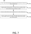
- FIG. 7 a flowchart illustrating a computer-implemented method 700 for detecting and tracking a coupler is illustrated.
- the computer-implemented method 700 may be (completely or partially) implemented on a computing environment similar to the computing environment 100 , such as, but not limited to, an embedded computer-implemented system of a vehicle.
- the method 700 starts at step 702 by accessing a video stream generated by a video camera being oriented so as to have the trailer in its field of view.
- the method 700 executes operating an object detection module on the video stream so as to detect the trailer and/or the coupler and establish one or more regions of interests being associated with at least one of the trailer and/or the coupler.
- the method 700 executes generating a vehicle referential point estimated position of a vehicle referential point.
- generating the vehicle referential point estimated position is further based on tracked estimated positions of tracked landmarks, each one of the tracked landmarks being associated with an object located in the field of view of the video camera.
- generating the vehicle referential point estimated position is further based on a dense depth map generated from the video stream.
- generating the vehicle referential point estimated position comprises operating, on the video stream, one of a simultaneous localization and mapping (SLAM) module, a depth estimation model and/or a visual odometry module.
- SLAM simultaneous localization and mapping
- the vehicle referential point estimated position is associated with a map of an environment in the field of view of the video camera.
- the map is generated as a set of 3-dimensional visual landmarks corresponding to a set of tracked image-space feature points.
- the method 700 executes generating a coupler position with respect to the vehicle referential point estimated position based on the one or more regions of interests and the vehicle referential point estimated position.
- generating the coupler position with respect to the vehicle referential point estimated position is further based on the tracked landmarks estimated positions.
- generating the coupler position with respect to the vehicle referential point comprises establishing which of the tracked landmarks belong to the trailer based on the one or more regions of interests established by the object detection module.
- generating the position of the coupler with respect to the vehicle referential point is based on feature descriptions associated with the tracked landmarks.
- generating the vehicle referential point estimated position and the tracked landmarks estimated positions (1) is operated on some but not all frames of the video stream and (2) comprises extrapolating remaining frames of the video stream.
- generating the coupler position with respect to the vehicle referential point is executed on some but not all frames of the video stream and remaining frames of the video stream are extrapolated.
- the method 700 further comprises generating a user interface that comprises a visual representation of the position of the coupler with respect to a coupling component of the vehicle.
- the visual representation is superimposed to the video stream.
- the vehicle comprises a propulsion system, a transmission system, a steering system and a brake system
- the method further comprises automatically controlling at least one the propulsion system, the transmission system, the steering system and/or the brake system based on the generated position of the coupler so as to align a trajectory of the coupling component of the vehicle with the coupler of the trailer.
- generating the coupler position with respect to the vehicle referential point is executed iteratively as the vehicle moves relative to the trailer. In some embodiments, generating the coupler position with respect to the vehicle referential point comprises determining a position of a center of the coupler.
- FIG. 8 a flowchart illustrating a computer-implemented method 800 for detecting and tracking an object of interest is illustrated.
- the computer-implemented method 800 may be (completely or partially) implemented on a computing environment similar to the computing environment 800 , such as, but not limited to, an embedded computer-implemented system enabling machine vision.
- the method 800 starts at step 802 by accessing a video stream generated by a video camera being oriented so as to have the object of interest in its field of view.
- the method 800 executes detecting the object of interest from a plurality of background objects located in the field of view of the video camera.
- the method 800 executes establishing one or more regions of interests being associated with the object of interest.
- the method 800 executes generating a first position, the first position being an estimated position of a referential point.
- generating the first position is further based on tracked landmarks estimated positions of tracked landmarks, each one of the tracked landmarks being associated with the object of interest or the background objects.
- the first position is associated with a map of an environment in the field of view of the video camera.
- the map is generated as a set of 3-dimensional visual landmarks corresponding to a set of tracked image-space feature points.
- the method 800 executes generating a second position, the second position being an estimated position of the object of interest with respect to the first position, the second position being generated based on the one or more regions of interests and the first position.
- generating the second position with respect to the first position is further based on 3-dimensional visual landmarks estimated positions.
- generating the second position with respect to the first position comprises operating, on the video stream, one of a simultaneous localization and mapping (SLAM) module, a depth estimation model and/or a visual odometry module.
- SLAM simultaneous localization and mapping
- generating the second position with respect to the first position comprises establishing which of the tracked landmarks belong to the object of interest based on the one or more regions of interests.
- generating the first position and the tracked landmarks estimated positions (1) is operated on some but not all frames of the video stream and (2) comprises extrapolating remaining frames of the video stream.
- generating the second position with respect to the first position is executed on some but not all frames of the video stream and remaining frames of the video stream are extrapolated.
Landscapes
- Engineering & Computer Science (AREA)
- Theoretical Computer Science (AREA)
- Multimedia (AREA)
- Physics & Mathematics (AREA)
- General Physics & Mathematics (AREA)
- Computer Vision & Pattern Recognition (AREA)
- Mechanical Engineering (AREA)
- Evolutionary Computation (AREA)
- Transportation (AREA)
- Health & Medical Sciences (AREA)
- Artificial Intelligence (AREA)
- Computing Systems (AREA)
- Databases & Information Systems (AREA)
- General Health & Medical Sciences (AREA)
- Medical Informatics (AREA)
- Software Systems (AREA)
- Signal Processing (AREA)
- Chemical & Material Sciences (AREA)
- Combustion & Propulsion (AREA)
- Image Analysis (AREA)
Abstract
Description
-
- accessing a video stream generated by a video camera being oriented so as to have the trailer in its field of view;
- operating an object detection module on the video stream so as to detect the trailer and/or the coupler and establish one or more regions of interests being associated with at least one of the trailer and/or the coupler;
- generating a vehicle referential point estimated position of a vehicle referential point; and
- generating a coupler position with respect to the vehicle referential point estimated position based on the one or more regions of interests and the vehicle referential point estimated position.
-
- accessing a video stream generated by a video camera being oriented so as to have the object of interest in its field of view;
- detecting the object of interest from a plurality of background objects located in the field of view of the video camera;
- establishing one or more regions of interests being associated with the object of interest;
- generating a first position, the first position being an estimated position of a referential point; and
- generating a second position, the second position being an estimated position of the object of interest with respect to the first position, the second position being generated based on the one or more regions of interests and the first position.
Claims (17)
Priority Applications (1)
| Application Number | Priority Date | Filing Date | Title |
|---|---|---|---|
| US16/698,600 US11030476B2 (en) | 2018-11-29 | 2019-11-27 | System and method for detecting and tracking objects |
Applications Claiming Priority (2)
| Application Number | Priority Date | Filing Date | Title |
|---|---|---|---|
| US201862772729P | 2018-11-29 | 2018-11-29 | |
| US16/698,600 US11030476B2 (en) | 2018-11-29 | 2019-11-27 | System and method for detecting and tracking objects |
Publications (2)
| Publication Number | Publication Date |
|---|---|
| US20200175311A1 US20200175311A1 (en) | 2020-06-04 |
| US11030476B2 true US11030476B2 (en) | 2021-06-08 |
Family
ID=70848337
Family Applications (1)
| Application Number | Title | Priority Date | Filing Date |
|---|---|---|---|
| US16/698,600 Active US11030476B2 (en) | 2018-11-29 | 2019-11-27 | System and method for detecting and tracking objects |
Country Status (2)
| Country | Link |
|---|---|
| US (1) | US11030476B2 (en) |
| CA (1) | CA3063011C (en) |
Cited By (15)
| Publication number | Priority date | Publication date | Assignee | Title |
|---|---|---|---|---|
| US20210347410A1 (en) * | 2020-05-08 | 2021-11-11 | Ford Global Technologies, Llc | Trailer gps location storage and recall for hitch assist operation |
| US20220180557A1 (en) * | 2020-12-09 | 2022-06-09 | Continental Automotive Systems, Inc. | Method for real-time tow ball detection |
| US20220414455A1 (en) * | 2021-06-29 | 2022-12-29 | Nvidia Corporation | Techniques for combining operations |
| US11610414B1 (en) * | 2019-03-04 | 2023-03-21 | Apple Inc. | Temporal and geometric consistency in physical setting understanding |
| US20240116497A1 (en) * | 2022-10-11 | 2024-04-11 | Toyota Motor Engineering & Manufacturing North America, Inc. | Trailer monitoring system |
| US20240217283A1 (en) * | 2022-12-31 | 2024-07-04 | Continental Autonomous Mobility US, LLC | Method for determining position of a trailer and device for determining position of a trailer |
| US12046045B2 (en) | 2022-01-06 | 2024-07-23 | Ford Global Technologies, Llc | Systems and methods for trailer hitch ball position and hitch angle |
| US20250014200A1 (en) * | 2021-11-24 | 2025-01-09 | XYZ Reality Limited | Using a neural network scene representation for mapping |
| US12281916B2 (en) | 2022-05-05 | 2025-04-22 | Here Global B.V. | Method, apparatus, and computer program product for map geometry generation based on data aggregation and conflation with statistical analysis |
| US12287225B2 (en) | 2022-05-05 | 2025-04-29 | Here Global B.V. | Method, apparatus, and computer program product for lane geometry generation based on graph estimation |
| US12292308B2 (en) | 2022-05-05 | 2025-05-06 | Here Global B.V. | Method, apparatus, and computer program product for map geometry generation based on object detection |
| US12384410B2 (en) | 2021-03-05 | 2025-08-12 | The Research Foundation For The State University Of New York | Task-motion planning for safe and efficient urban driving |
| US12535336B2 (en) | 2022-05-05 | 2026-01-27 | Here Global B.V. | Method, apparatus, and computer program product for map geometry generation based on data aggregation and conflation |
| US12546626B2 (en) | 2022-05-05 | 2026-02-10 | Here Global B.V. | Method, apparatus, and computer program product for probe data-based geometry generation |
| US12619868B2 (en) * | 2021-06-29 | 2026-05-05 | Nvidia Corporation | Techniques for combining independent operations in a graph structure |
Families Citing this family (54)
| Publication number | Priority date | Publication date | Assignee | Title |
|---|---|---|---|---|
| DE112019000049T5 (en) | 2018-02-18 | 2020-01-23 | Nvidia Corporation | OBJECT DETECTION AND DETECTION SECURITY SUITABLE FOR AUTONOMOUS DRIVING |
| US10997433B2 (en) | 2018-02-27 | 2021-05-04 | Nvidia Corporation | Real-time detection of lanes and boundaries by autonomous vehicles |
| CN110494863B (en) | 2018-03-15 | 2024-02-09 | 辉达公司 | Determining drivable free space of an autonomous vehicle |
| US12585275B1 (en) | 2018-06-13 | 2026-03-24 | Nvidia Corporation | Loss scaling for neural networks |
| US10937186B2 (en) * | 2018-12-19 | 2021-03-02 | Fca Us Llc | Techniques for precisely locating landmarks in monocular camera images with deep learning |
| WO2020140047A1 (en) * | 2018-12-28 | 2020-07-02 | Nvidia Corporation | Distance to obstacle detection in autonomous machine applications |
| US11182916B2 (en) | 2018-12-28 | 2021-11-23 | Nvidia Corporation | Distance to obstacle detection in autonomous machine applications |
| US11170299B2 (en) | 2018-12-28 | 2021-11-09 | Nvidia Corporation | Distance estimation to objects and free-space boundaries in autonomous machine applications |
| WO2020185779A1 (en) | 2019-03-11 | 2020-09-17 | Nvidia Corporation | Intersection detection and classification in autonomous machine applications |
| DE102019212604A1 (en) * | 2019-08-22 | 2021-02-25 | Robert Bosch Gmbh | Method and control device for determining an evaluation algorithm from a plurality of available evaluation algorithms for processing sensor data of a vehicle sensor of a vehicle |
| US11788861B2 (en) | 2019-08-31 | 2023-10-17 | Nvidia Corporation | Map creation and localization for autonomous driving applications |
| EP4032066B1 (en) | 2019-09-19 | 2025-04-02 | Continental Autonomous Mobility US, LLC | Automatic trailer camera calibration |
| US11080862B2 (en) * | 2019-11-18 | 2021-08-03 | Ncku Research And Development Foundation | Reliability based keyframe switching system and method adaptable to ICP |
| US11630454B2 (en) | 2019-12-09 | 2023-04-18 | Plusai, Inc. | System and method for coordinating landmark based collaborative sensor calibration |
| US11875682B2 (en) | 2019-12-09 | 2024-01-16 | Plusai, Inc. | System and method for coordinating collaborative sensor calibration |
| US11087496B2 (en) * | 2019-12-09 | 2021-08-10 | Plusai Limited | System and method for trailer pose estimation |
| US11372406B2 (en) | 2019-12-09 | 2022-06-28 | Plusai, Inc. | System and method for collaborative sensor calibration |
| US11852730B2 (en) | 2019-12-09 | 2023-12-26 | Plusai, Inc. | System and method for collaborative calibration via landmark |
| US11579632B2 (en) | 2019-12-09 | 2023-02-14 | Plusai, Inc. | System and method for assisting collaborative sensor calibration |
| CN111797758A (en) * | 2020-07-03 | 2020-10-20 | 成都理工大学 | An identification and positioning technology for plastic bottles |
| CN112561954B (en) * | 2020-09-11 | 2023-07-14 | 浙江大华技术股份有限公司 | Method and device for determining target object tracking trajectory, and storage medium |
| US11403767B2 (en) * | 2020-09-15 | 2022-08-02 | Connaught Electronics, Ltd. | Method and apparatus for detecting a trailer, tow-ball, and coupler for trailer hitch assistance and jackknife prevention |
| US11978266B2 (en) | 2020-10-21 | 2024-05-07 | Nvidia Corporation | Occupant attentiveness and cognitive load monitoring for autonomous and semi-autonomous driving applications |
| CN112487920B (en) * | 2020-11-25 | 2022-03-15 | 电子科技大学 | A Climbing Behavior Recognition Method Based on Convolutional Neural Networks |
| US12055944B2 (en) * | 2020-12-09 | 2024-08-06 | Continental Autonomous Mobility US, LLC | Method for determining a tow hitch position |
| CN112507894A (en) * | 2020-12-14 | 2021-03-16 | 天时地理(深圳)智能科技有限公司 | Vehicle identification tracking method and system |
| CN112669335B (en) * | 2021-01-27 | 2024-11-05 | 东软睿驰汽车技术(沈阳)有限公司 | Vehicle perception method, device, electronic device, and machine-readable storage medium |
| CN112985439B (en) * | 2021-02-08 | 2023-10-17 | 青岛大学 | Pedestrian blocking state prediction method based on YOLOv3 and Kalman filtering |
| EP4057226B1 (en) * | 2021-03-09 | 2025-01-29 | Samsung Electronics Co., Ltd. | Method and apparatus for estimating pose of device |
| CN112907634B (en) * | 2021-03-18 | 2023-06-20 | 沈阳理工大学 | UAV-based vehicle tracking method |
| US12327277B2 (en) | 2021-04-12 | 2025-06-10 | Snap Inc. | Home based augmented reality shopping |
| US12299923B2 (en) * | 2021-04-27 | 2025-05-13 | Continental Autonomous Mobility US, LLC | System and method for estimating relative trailer angle |
| CN113435336B (en) * | 2021-06-28 | 2022-10-04 | 安徽一视科技有限公司 | Running intelligent timing system and method based on artificial intelligence |
| TWI762365B (en) * | 2021-06-29 | 2022-04-21 | 晶睿通訊股份有限公司 | Image identification method and image surveillance apparatus |
| DE102021117911A1 (en) | 2021-07-12 | 2023-01-12 | Connaught Electronics Ltd. | Locating a trailer hitch |
| CN113506278B (en) * | 2021-07-19 | 2022-06-14 | 同济大学 | Road sign auxiliary detection control method based on YOLO-V3 |
| CN113538391B (en) * | 2021-07-25 | 2022-08-02 | 吉林大学 | Photovoltaic defect detection method based on Yolov4 and thermal infrared image |
| US12014520B2 (en) | 2021-08-26 | 2024-06-18 | Toyota Motor Engineering & Manufacturing North America, Inc. | Systems and methods for detecting objects within an image in a wide-view format |
| CN114029588A (en) * | 2021-11-26 | 2022-02-11 | 江苏永大化工设备有限公司 | Automatic adjusting system for gas shielded welding process parameters |
| US12002253B2 (en) | 2021-11-29 | 2024-06-04 | Automotive Research & Testing Center | Feature point integration positioning system, feature point integration positioning method and non-transitory computer-readable memory |
| US12151704B2 (en) * | 2021-12-22 | 2024-11-26 | Continental Autonomous Mobility US, LLC | Autonomous vehicle trailer hitch coupling system |
| US12412205B2 (en) | 2021-12-30 | 2025-09-09 | Snap Inc. | Method, system, and medium for augmented reality product recommendations |
| US11928783B2 (en) | 2021-12-30 | 2024-03-12 | Snap Inc. | AR position and orientation along a plane |
| US12499626B2 (en) | 2021-12-30 | 2025-12-16 | Snap Inc. | AR item placement in a video |
| US11887260B2 (en) | 2021-12-30 | 2024-01-30 | Snap Inc. | AR position indicator |
| US11954762B2 (en) * | 2022-01-19 | 2024-04-09 | Snap Inc. | Object replacement system |
| CN115222731B (en) * | 2022-09-07 | 2022-12-02 | 西南交通大学 | An abnormal detection method for train fasteners based on two-dimensional image to point cloud mapping |
| US20240112471A1 (en) * | 2022-09-30 | 2024-04-04 | Continental Automotive Systems, Inc. | System and Method for Trailer and Trailer Coupler Recognition via Classification |
| CN115742957A (en) * | 2022-11-30 | 2023-03-07 | 东土华盛科技有限公司 | Method and device for controlling vehicle docking and vehicle |
| DE102022004590A1 (en) * | 2022-12-07 | 2024-06-13 | Jost-Werke Deutschland Gmbh | Camera system for accurate coupling of a trailer to a towing vehicle |
| CN116823876A (en) * | 2023-02-08 | 2023-09-29 | 湖北文理学院 | Mobile target positioning method, equipment, storage medium and device |
| CN116580066B (en) * | 2023-07-04 | 2023-10-03 | 广州英码信息科技有限公司 | Pedestrian target tracking method under low frame rate scene and readable storage medium |
| US12441242B2 (en) * | 2023-12-05 | 2025-10-14 | GM Global Technology Operations LLC | System and method for detecting a trailer coupler and planning a trajectory |
| DE102024001840A1 (en) * | 2024-06-06 | 2025-12-11 | Jost-Werke Deutschland Gmbh | Safety system for the accurate coupling of a trailer to a towing vehicle |
Citations (73)
| Publication number | Priority date | Publication date | Assignee | Title |
|---|---|---|---|---|
| US20050074143A1 (en) * | 2003-10-02 | 2005-04-07 | Nissan Motor Co., Ltd. | Vehicle backing assist apparatus and vehicle backing assist method |
| US7777615B2 (en) * | 2008-03-20 | 2010-08-17 | Toyota Motor Engineering & Manufacturing North America, Inc. | System for assisting the attachment of a trailer to a vehicle |
| US20140012465A1 (en) * | 2012-07-05 | 2014-01-09 | Uusi, Llc | Vehicle trailer connect system |
| US20140125795A1 (en) * | 2012-11-05 | 2014-05-08 | James Arnold Yerke | Trailer Coupling Assistant |
| US20140200759A1 (en) * | 2011-01-26 | 2014-07-17 | Magna Electronics Inc. | Rear vision system with trailer angle detection |
| US8798842B2 (en) * | 2011-01-25 | 2014-08-05 | Teleswivel, Llc | Trailer hitch alignment systems and methods |
| US20140309887A1 (en) * | 2011-04-19 | 2014-10-16 | Ford Global Technologies, Llc | Trailer angle detection target plausibility |
| US8888121B2 (en) * | 2007-01-25 | 2014-11-18 | Target Hitch Llc | Towing vehicle guidance for trailer hitch connection |
| US8888120B2 (en) * | 2007-01-25 | 2014-11-18 | Target Hitch Llc | Towing vehicle guidance for trailer hitch connection |
| US20150115571A1 (en) * | 2013-10-24 | 2015-04-30 | GM Global Technology Operations LLC | Smart tow |
| US20150138340A1 (en) * | 2011-04-19 | 2015-05-21 | Ford Global Technologies, Llc | Target monitoring system and method |
| US20150149040A1 (en) * | 2012-08-03 | 2015-05-28 | Volkswagen Aktiengesellschaft | Method and device for maneuvering a trailer |
| US20160039456A1 (en) * | 2011-04-19 | 2016-02-11 | Ford Global Technologies, Llc | Trailer backup offset determination |
| US20160059888A1 (en) * | 2013-04-26 | 2016-03-03 | Jaguar Land Rover Limited | System for a Towing Vehicle |
| US9296421B2 (en) * | 2014-03-06 | 2016-03-29 | Ford Global Technologies, Llc | Vehicle target identification using human gesture recognition |
| US20160210512A1 (en) * | 2015-01-16 | 2016-07-21 | Avigilon Fortress Corporation | System and method for detecting, tracking, and classifiying objects |
| US20160288601A1 (en) * | 2015-04-01 | 2016-10-06 | Robert Bosch Gmbh | Trailer coupling assistance system with vehicle video camera |
| US20160378118A1 (en) * | 2015-06-23 | 2016-12-29 | GM Global Technology Operations LLC | Smart trailer hitch control using hmi assisted visual servoing |
| US20160375831A1 (en) * | 2015-06-23 | 2016-12-29 | GM Global Technology Operations LLC | Hitching assist with pan/zoom and virtual top-view |
| US20170174023A1 (en) * | 2015-12-17 | 2017-06-22 | Ford Global Technologies, Llc | Hitch angle detection for trailer backup assist system |
| US20170341583A1 (en) | 2016-05-27 | 2017-11-30 | GM Global Technology Operations LLC | Systems and methods for towing vehicle and trailer with surround view imaging devices |
| US9834140B2 (en) * | 2014-07-22 | 2017-12-05 | Fca Us Llc | Trailer hitch guidance method |
| US9854209B2 (en) * | 2011-04-19 | 2017-12-26 | Ford Global Technologies, Llc | Display system utilizing vehicle and trailer dynamics |
| US20180001721A1 (en) * | 2016-06-29 | 2018-01-04 | Volkswagen Ag | Assisting method and docking assistant for coupling a motor vehicle to a trailer |
| US20180029429A1 (en) * | 2016-07-28 | 2018-02-01 | Robert Bosch Gmbh | Systems and methods for a human machine interface for a trailer hitch system |
| US20180061102A1 (en) * | 2015-02-16 | 2018-03-01 | Denso Corporation | Drive assist device and drive assist method |
| US20180181142A1 (en) * | 2015-04-10 | 2018-06-28 | Robert Bosch Gmbh | Object position measurement with automotive camera using vehicle motion data |
| US20180192035A1 (en) * | 2017-01-04 | 2018-07-05 | Qualcomm Incorporated | Systems and methods for object location |
| US10017115B2 (en) * | 2015-11-11 | 2018-07-10 | Ford Global Technologies, Llc | Trailer monitoring system and method |
| US10035457B2 (en) * | 2013-04-26 | 2018-07-31 | Jaguar Land Rover Limited | Vehicle hitch assistance system |
| US20180253106A1 (en) * | 2017-03-01 | 2018-09-06 | Aisin Seiki Kabushiki Kaisha | Periphery monitoring device |
| US10150505B2 (en) * | 2015-04-14 | 2018-12-11 | Continental Automotive Systems, Inc. | Automated hitching assist system |
| US10155478B2 (en) * | 2015-12-17 | 2018-12-18 | Ford Global Technologies, Llc | Centerline method for trailer hitch angle detection |
| US20180361929A1 (en) * | 2017-06-20 | 2018-12-20 | Ford Global Technologies, Llc | Vehicle rear object proximity system using multiple cameras |
| US20190035101A1 (en) * | 2017-07-27 | 2019-01-31 | Here Global B.V. | Method, apparatus, and system for real-time object detection using a cursor recurrent neural network |
| US10220839B2 (en) * | 2016-06-20 | 2019-03-05 | Ford Global Technologies, Llc | Vehicle hitch detection system and method |
| US20190092109A1 (en) * | 2017-09-25 | 2019-03-28 | Continental Automotive Systems, Inc. | Automated Trailer Hitching Using Image Coordinates |
| US10266023B2 (en) * | 2017-05-01 | 2019-04-23 | Ford Global Technologies, Llc | System to automate hitching a trailer |
| US20190188505A1 (en) * | 2017-12-14 | 2019-06-20 | COM-IoT Technologies | Distracted driver detection |
| US10363874B2 (en) * | 2017-09-19 | 2019-07-30 | Ford Global Technologies, Llc | Hitch assist system with hitch coupler identification feature and hitch coupler height estimation |
| US20190258251A1 (en) * | 2017-11-10 | 2019-08-22 | Nvidia Corporation | Systems and methods for safe and reliable autonomous vehicles |
| US10427717B2 (en) * | 2017-09-19 | 2019-10-01 | Ford Global Technologies, Llc | Hitch assist system with hitch coupler identification feature and hitch coupler height estimation |
| US10427716B2 (en) * | 2017-09-12 | 2019-10-01 | Ford Global Technologies, Llc | Hitch assist system and method |
| US10435070B2 (en) * | 2016-01-14 | 2019-10-08 | Continental Automotive Systems, Inc. | Vehicle-trailer backing system having targetless hitch angle detection and trailer geometry learning |
| US20190308473A1 (en) * | 2018-04-04 | 2019-10-10 | Continental Automotive Systems, Inc. | Vehicle-Trailer Distance Detection Device and Method |
| US20190335100A1 (en) * | 2018-04-27 | 2019-10-31 | Continental Automotive Systems, Inc. | Device and Method For Determining A Center of A Trailer Tow Coupler |
| US20190340787A1 (en) * | 2018-05-01 | 2019-11-07 | Continental Automotive Systems, Inc. | Real-Time Trailer Coupler Localization and Tracking |
| US20190337343A1 (en) * | 2018-05-01 | 2019-11-07 | Continental Automotive Systems, Inc. | Coupler And Tow-bar Detection For Automated Trailer Hitching Via Cloud Points |
| US20190339704A1 (en) * | 2018-05-01 | 2019-11-07 | Continental Automotive Systems, Inc. | Trailer Detection and Autonomous Hitching |
| US20190346856A1 (en) * | 2018-05-08 | 2019-11-14 | Continental Automotive Systems, Inc. | Visual Object Tracker |
| US20190347498A1 (en) * | 2018-05-09 | 2019-11-14 | Ford Global Technologies, Llc | Systems and methods for automated detection of trailer properties |
| US10479152B2 (en) * | 2017-11-03 | 2019-11-19 | Ford Global Technologies, Llc | Compensation for trailer coupler height in automatic hitch operation |
| US20190378282A1 (en) * | 2018-06-08 | 2019-12-12 | Ford Global Technologies, Llc | Object tracking in blind-spot |
| US20200001920A1 (en) * | 2018-07-02 | 2020-01-02 | Ohio State Innovation Foundation | Systems and methods for preventing a jackknife condition in a tractor-trailer system |
| US20200001855A1 (en) * | 2018-06-28 | 2020-01-02 | Aisin Seiki Kabushiki Kaisha | Driving support device |
| US10543870B1 (en) * | 2018-07-18 | 2020-01-28 | Ford Global Technologies, Llc | Hitch assist system |
| US20200039517A1 (en) * | 2018-08-03 | 2020-02-06 | Continental Automotive Systems, Inc. | Automated Reversing By Choice of Target Location |
| US20200055356A1 (en) * | 2018-08-17 | 2020-02-20 | Ford Global Technologies, Llc | Hitch assist system |
| US20200073398A1 (en) * | 2018-08-30 | 2020-03-05 | Ford Global Technologies, Llc | System and methods for reverse braking during automated hitch alignment |
| US20200070724A1 (en) * | 2018-09-04 | 2020-03-05 | Volkswagen Aktiengesellschaft | Method and system for automatically detecting a coupling maneuver of a transportation vehicle to a trailer |
| US20200101897A1 (en) * | 2017-04-19 | 2020-04-02 | Robert Bosch Gmbh | Methods and systems for aligning a vehicle with a trailer |
| US20200118423A1 (en) * | 2017-04-05 | 2020-04-16 | Carnegie Mellon University | Deep Learning Methods For Estimating Density and/or Flow of Objects, and Related Methods and Software |
| US10632919B2 (en) * | 2018-06-27 | 2020-04-28 | Ford Global Technologies, Llc | Vehicle hitch assist system |
| US20200130744A1 (en) * | 2018-10-30 | 2020-04-30 | Ford Global Technologies, Llc | Application of auxiliary lighting in automatic hitch operation |
| US20200175718A1 (en) * | 2018-12-04 | 2020-06-04 | Here Global B.V. | Method and apparatus for providing feature triangulation |
| US20200226377A1 (en) * | 2020-03-25 | 2020-07-16 | Intel Corporation | Robust object detection and classification using static-based cameras and events-based cameras. |
| US20200226430A1 (en) * | 2020-03-26 | 2020-07-16 | Intel Corporation | Devices and methods for accurately identifying objects in a vehicle's environment |
| US20200242381A1 (en) * | 2020-03-26 | 2020-07-30 | Intel Corporation | Methods and devices for triggering vehicular actions based on passenger actions |
| US20200247471A1 (en) * | 2019-02-01 | 2020-08-06 | Carit Automotive GmbH & Co. KG | Vehicle park assist systems |
| US10744943B1 (en) * | 2019-04-08 | 2020-08-18 | Ford Global Technologies, Llc | System and method for trailer alignment |
| US10755115B2 (en) * | 2017-12-29 | 2020-08-25 | Here Global B.V. | Method, apparatus, and system for generating synthetic image data for machine learning |
| US20200272847A1 (en) * | 2019-02-27 | 2020-08-27 | Here Global B.V. | Method, apparatus, and system for generating feature correspondence from camera geometry |
| US20200284607A1 (en) * | 2019-03-08 | 2020-09-10 | Aptiv Technologies Limited | Object location indicator system and method |
-
2019
- 2019-11-27 US US16/698,600 patent/US11030476B2/en active Active
- 2019-11-28 CA CA3063011A patent/CA3063011C/en active Active
Patent Citations (91)
| Publication number | Priority date | Publication date | Assignee | Title |
|---|---|---|---|---|
| US20050074143A1 (en) * | 2003-10-02 | 2005-04-07 | Nissan Motor Co., Ltd. | Vehicle backing assist apparatus and vehicle backing assist method |
| US8888121B2 (en) * | 2007-01-25 | 2014-11-18 | Target Hitch Llc | Towing vehicle guidance for trailer hitch connection |
| US8888120B2 (en) * | 2007-01-25 | 2014-11-18 | Target Hitch Llc | Towing vehicle guidance for trailer hitch connection |
| US7777615B2 (en) * | 2008-03-20 | 2010-08-17 | Toyota Motor Engineering & Manufacturing North America, Inc. | System for assisting the attachment of a trailer to a vehicle |
| US8798842B2 (en) * | 2011-01-25 | 2014-08-05 | Teleswivel, Llc | Trailer hitch alignment systems and methods |
| US20140200759A1 (en) * | 2011-01-26 | 2014-07-17 | Magna Electronics Inc. | Rear vision system with trailer angle detection |
| US20150138340A1 (en) * | 2011-04-19 | 2015-05-21 | Ford Global Technologies, Llc | Target monitoring system and method |
| US20200031392A1 (en) * | 2011-04-19 | 2020-01-30 | Ford Global Technologies, Llc | Trailer backup offset determination |
| US9937953B2 (en) * | 2011-04-19 | 2018-04-10 | Ford Global Technologies, Llc | Trailer backup offset determination |
| US20140309887A1 (en) * | 2011-04-19 | 2014-10-16 | Ford Global Technologies, Llc | Trailer angle detection target plausibility |
| US9854209B2 (en) * | 2011-04-19 | 2017-12-26 | Ford Global Technologies, Llc | Display system utilizing vehicle and trailer dynamics |
| US10471989B2 (en) * | 2011-04-19 | 2019-11-12 | Ford Global Technologies, Llc | Trailer backup offset determination |
| US20160039456A1 (en) * | 2011-04-19 | 2016-02-11 | Ford Global Technologies, Llc | Trailer backup offset determination |
| US20140012465A1 (en) * | 2012-07-05 | 2014-01-09 | Uusi, Llc | Vehicle trailer connect system |
| US20150149040A1 (en) * | 2012-08-03 | 2015-05-28 | Volkswagen Aktiengesellschaft | Method and device for maneuvering a trailer |
| US20140125795A1 (en) * | 2012-11-05 | 2014-05-08 | James Arnold Yerke | Trailer Coupling Assistant |
| US20160059888A1 (en) * | 2013-04-26 | 2016-03-03 | Jaguar Land Rover Limited | System for a Towing Vehicle |
| US10035457B2 (en) * | 2013-04-26 | 2018-07-31 | Jaguar Land Rover Limited | Vehicle hitch assistance system |
| US20150115571A1 (en) * | 2013-10-24 | 2015-04-30 | GM Global Technology Operations LLC | Smart tow |
| US9296421B2 (en) * | 2014-03-06 | 2016-03-29 | Ford Global Technologies, Llc | Vehicle target identification using human gesture recognition |
| US9834140B2 (en) * | 2014-07-22 | 2017-12-05 | Fca Us Llc | Trailer hitch guidance method |
| US20180260633A1 (en) * | 2015-01-16 | 2018-09-13 | Avigilon Fortress Corporation | System and method for detecting, tracking, and classifiying objects |
| US9996753B2 (en) * | 2015-01-16 | 2018-06-12 | Avigilon Fortress Corporation | System and method for detecting, tracking, and classifiying objects |
| US10210397B2 (en) * | 2015-01-16 | 2019-02-19 | Avigilon Fortress Corporation | System and method for detecting, tracking, and classifiying objects |
| US10664706B2 (en) * | 2015-01-16 | 2020-05-26 | Avigilon Fortress Corporation | System and method for detecting, tracking, and classifying objects |
| US9710712B2 (en) * | 2015-01-16 | 2017-07-18 | Avigilon Fortress Corporation | System and method for detecting, tracking, and classifiying objects |
| US20160210512A1 (en) * | 2015-01-16 | 2016-07-21 | Avigilon Fortress Corporation | System and method for detecting, tracking, and classifiying objects |
| US20170286778A1 (en) * | 2015-01-16 | 2017-10-05 | Avigilon Fortress Corporation | System and method for detecting, tracking, and classifiying objects |
| US20190163983A1 (en) * | 2015-01-16 | 2019-05-30 | Avigilon Fortress Corporation | System and method for detecting, tracking, and classifying objects |
| US20180061102A1 (en) * | 2015-02-16 | 2018-03-01 | Denso Corporation | Drive assist device and drive assist method |
| US20160288601A1 (en) * | 2015-04-01 | 2016-10-06 | Robert Bosch Gmbh | Trailer coupling assistance system with vehicle video camera |
| US20180181142A1 (en) * | 2015-04-10 | 2018-06-28 | Robert Bosch Gmbh | Object position measurement with automotive camera using vehicle motion data |
| US10150505B2 (en) * | 2015-04-14 | 2018-12-11 | Continental Automotive Systems, Inc. | Automated hitching assist system |
| US20160375831A1 (en) * | 2015-06-23 | 2016-12-29 | GM Global Technology Operations LLC | Hitching assist with pan/zoom and virtual top-view |
| US20160378118A1 (en) * | 2015-06-23 | 2016-12-29 | GM Global Technology Operations LLC | Smart trailer hitch control using hmi assisted visual servoing |
| US10017115B2 (en) * | 2015-11-11 | 2018-07-10 | Ford Global Technologies, Llc | Trailer monitoring system and method |
| US9796228B2 (en) * | 2015-12-17 | 2017-10-24 | Ford Global Technologies, Llc | Hitch angle detection for trailer backup assist system |
| US20170174023A1 (en) * | 2015-12-17 | 2017-06-22 | Ford Global Technologies, Llc | Hitch angle detection for trailer backup assist system |
| US10155478B2 (en) * | 2015-12-17 | 2018-12-18 | Ford Global Technologies, Llc | Centerline method for trailer hitch angle detection |
| US10435070B2 (en) * | 2016-01-14 | 2019-10-08 | Continental Automotive Systems, Inc. | Vehicle-trailer backing system having targetless hitch angle detection and trailer geometry learning |
| US10259390B2 (en) * | 2016-05-27 | 2019-04-16 | GM Global Technology Operations LLC | Systems and methods for towing vehicle and trailer with surround view imaging devices |
| US20170341583A1 (en) | 2016-05-27 | 2017-11-30 | GM Global Technology Operations LLC | Systems and methods for towing vehicle and trailer with surround view imaging devices |
| US10220839B2 (en) * | 2016-06-20 | 2019-03-05 | Ford Global Technologies, Llc | Vehicle hitch detection system and method |
| US20180001721A1 (en) * | 2016-06-29 | 2018-01-04 | Volkswagen Ag | Assisting method and docking assistant for coupling a motor vehicle to a trailer |
| US20180029429A1 (en) * | 2016-07-28 | 2018-02-01 | Robert Bosch Gmbh | Systems and methods for a human machine interface for a trailer hitch system |
| US10630962B2 (en) * | 2017-01-04 | 2020-04-21 | Qualcomm Incorporated | Systems and methods for object location |
| US20180192035A1 (en) * | 2017-01-04 | 2018-07-05 | Qualcomm Incorporated | Systems and methods for object location |
| US20180253106A1 (en) * | 2017-03-01 | 2018-09-06 | Aisin Seiki Kabushiki Kaisha | Periphery monitoring device |
| US10733876B2 (en) * | 2017-04-05 | 2020-08-04 | Carnegie Mellon University | Deep learning methods for estimating density and/or flow of objects, and related methods and software |
| US20200118423A1 (en) * | 2017-04-05 | 2020-04-16 | Carnegie Mellon University | Deep Learning Methods For Estimating Density and/or Flow of Objects, and Related Methods and Software |
| US20200101897A1 (en) * | 2017-04-19 | 2020-04-02 | Robert Bosch Gmbh | Methods and systems for aligning a vehicle with a trailer |
| US10266023B2 (en) * | 2017-05-01 | 2019-04-23 | Ford Global Technologies, Llc | System to automate hitching a trailer |
| US20180361929A1 (en) * | 2017-06-20 | 2018-12-20 | Ford Global Technologies, Llc | Vehicle rear object proximity system using multiple cameras |
| US20190035101A1 (en) * | 2017-07-27 | 2019-01-31 | Here Global B.V. | Method, apparatus, and system for real-time object detection using a cursor recurrent neural network |
| US10402995B2 (en) * | 2017-07-27 | 2019-09-03 | Here Global B.V. | Method, apparatus, and system for real-time object detection using a cursor recurrent neural network |
| US10427716B2 (en) * | 2017-09-12 | 2019-10-01 | Ford Global Technologies, Llc | Hitch assist system and method |
| US10427717B2 (en) * | 2017-09-19 | 2019-10-01 | Ford Global Technologies, Llc | Hitch assist system with hitch coupler identification feature and hitch coupler height estimation |
| US10363874B2 (en) * | 2017-09-19 | 2019-07-30 | Ford Global Technologies, Llc | Hitch assist system with hitch coupler identification feature and hitch coupler height estimation |
| US20190092109A1 (en) * | 2017-09-25 | 2019-03-28 | Continental Automotive Systems, Inc. | Automated Trailer Hitching Using Image Coordinates |
| US10479152B2 (en) * | 2017-11-03 | 2019-11-19 | Ford Global Technologies, Llc | Compensation for trailer coupler height in automatic hitch operation |
| US20190258251A1 (en) * | 2017-11-10 | 2019-08-22 | Nvidia Corporation | Systems and methods for safe and reliable autonomous vehicles |
| US20190188505A1 (en) * | 2017-12-14 | 2019-06-20 | COM-IoT Technologies | Distracted driver detection |
| US10769461B2 (en) * | 2017-12-14 | 2020-09-08 | COM-IoT Technologies | Distracted driver detection |
| US10755115B2 (en) * | 2017-12-29 | 2020-08-25 | Here Global B.V. | Method, apparatus, and system for generating synthetic image data for machine learning |
| US20190308473A1 (en) * | 2018-04-04 | 2019-10-10 | Continental Automotive Systems, Inc. | Vehicle-Trailer Distance Detection Device and Method |
| US20190335100A1 (en) * | 2018-04-27 | 2019-10-31 | Continental Automotive Systems, Inc. | Device and Method For Determining A Center of A Trailer Tow Coupler |
| US20190340787A1 (en) * | 2018-05-01 | 2019-11-07 | Continental Automotive Systems, Inc. | Real-Time Trailer Coupler Localization and Tracking |
| US20190339704A1 (en) * | 2018-05-01 | 2019-11-07 | Continental Automotive Systems, Inc. | Trailer Detection and Autonomous Hitching |
| US20190337343A1 (en) * | 2018-05-01 | 2019-11-07 | Continental Automotive Systems, Inc. | Coupler And Tow-bar Detection For Automated Trailer Hitching Via Cloud Points |
| US20190346856A1 (en) * | 2018-05-08 | 2019-11-14 | Continental Automotive Systems, Inc. | Visual Object Tracker |
| US20190347498A1 (en) * | 2018-05-09 | 2019-11-14 | Ford Global Technologies, Llc | Systems and methods for automated detection of trailer properties |
| US10628690B2 (en) * | 2018-05-09 | 2020-04-21 | Ford Global Technologies, Llc | Systems and methods for automated detection of trailer properties |
| US20190378282A1 (en) * | 2018-06-08 | 2019-12-12 | Ford Global Technologies, Llc | Object tracking in blind-spot |
| US10632919B2 (en) * | 2018-06-27 | 2020-04-28 | Ford Global Technologies, Llc | Vehicle hitch assist system |
| US20200001855A1 (en) * | 2018-06-28 | 2020-01-02 | Aisin Seiki Kabushiki Kaisha | Driving support device |
| US20200001920A1 (en) * | 2018-07-02 | 2020-01-02 | Ohio State Innovation Foundation | Systems and methods for preventing a jackknife condition in a tractor-trailer system |
| US10543870B1 (en) * | 2018-07-18 | 2020-01-28 | Ford Global Technologies, Llc | Hitch assist system |
| US20200039517A1 (en) * | 2018-08-03 | 2020-02-06 | Continental Automotive Systems, Inc. | Automated Reversing By Choice of Target Location |
| US10632803B2 (en) * | 2018-08-17 | 2020-04-28 | Ford Global Technologies, Llc | Hitch assist system |
| US20200055356A1 (en) * | 2018-08-17 | 2020-02-20 | Ford Global Technologies, Llc | Hitch assist system |
| US20200073398A1 (en) * | 2018-08-30 | 2020-03-05 | Ford Global Technologies, Llc | System and methods for reverse braking during automated hitch alignment |
| US20200070724A1 (en) * | 2018-09-04 | 2020-03-05 | Volkswagen Aktiengesellschaft | Method and system for automatically detecting a coupling maneuver of a transportation vehicle to a trailer |
| US20200130744A1 (en) * | 2018-10-30 | 2020-04-30 | Ford Global Technologies, Llc | Application of auxiliary lighting in automatic hitch operation |
| US20200175718A1 (en) * | 2018-12-04 | 2020-06-04 | Here Global B.V. | Method and apparatus for providing feature triangulation |
| US20200247471A1 (en) * | 2019-02-01 | 2020-08-06 | Carit Automotive GmbH & Co. KG | Vehicle park assist systems |
| US20200272847A1 (en) * | 2019-02-27 | 2020-08-27 | Here Global B.V. | Method, apparatus, and system for generating feature correspondence from camera geometry |
| US20200284607A1 (en) * | 2019-03-08 | 2020-09-10 | Aptiv Technologies Limited | Object location indicator system and method |
| US10744943B1 (en) * | 2019-04-08 | 2020-08-18 | Ford Global Technologies, Llc | System and method for trailer alignment |
| US20200226377A1 (en) * | 2020-03-25 | 2020-07-16 | Intel Corporation | Robust object detection and classification using static-based cameras and events-based cameras. |
| US20200242381A1 (en) * | 2020-03-26 | 2020-07-30 | Intel Corporation | Methods and devices for triggering vehicular actions based on passenger actions |
| US20200226430A1 (en) * | 2020-03-26 | 2020-07-16 | Intel Corporation | Devices and methods for accurately identifying objects in a vehicle's environment |
Non-Patent Citations (2)
| Title |
|---|
| Kaneko et al., "Mask-Slam: Robust feature-based monocular SLAM by masking using semantic segmentation", IEEE/CVF Conference on Computer Vision and Pattern Recognition Workshops (CVPRW), 2018, pp. 371-379. |
| Microsoft / AirSim, "Open source simulator for autonomous vehicles built on Unreal Engine / Unity, from Microsoft AI & Research", https://github.com/Microsoft/AirSim accessed Apr. 5, 2020, pdf 6 pages. |
Cited By (19)
| Publication number | Priority date | Publication date | Assignee | Title |
|---|---|---|---|---|
| US11610414B1 (en) * | 2019-03-04 | 2023-03-21 | Apple Inc. | Temporal and geometric consistency in physical setting understanding |
| US12286156B2 (en) * | 2020-05-08 | 2025-04-29 | Ford Global Technologies, Llc | Trailer GPS location storage and recall for hitch assist operation |
| US20210347410A1 (en) * | 2020-05-08 | 2021-11-11 | Ford Global Technologies, Llc | Trailer gps location storage and recall for hitch assist operation |
| US11676300B2 (en) * | 2020-12-09 | 2023-06-13 | Continental Autonomous Mobility US, LLC | Method for real-time tow ball detection |
| US20220180557A1 (en) * | 2020-12-09 | 2022-06-09 | Continental Automotive Systems, Inc. | Method for real-time tow ball detection |
| US12384410B2 (en) | 2021-03-05 | 2025-08-12 | The Research Foundation For The State University Of New York | Task-motion planning for safe and efficient urban driving |
| US20220414455A1 (en) * | 2021-06-29 | 2022-12-29 | Nvidia Corporation | Techniques for combining operations |
| US12619868B2 (en) * | 2021-06-29 | 2026-05-05 | Nvidia Corporation | Techniques for combining independent operations in a graph structure |
| US20250014200A1 (en) * | 2021-11-24 | 2025-01-09 | XYZ Reality Limited | Using a neural network scene representation for mapping |
| US12046045B2 (en) | 2022-01-06 | 2024-07-23 | Ford Global Technologies, Llc | Systems and methods for trailer hitch ball position and hitch angle |
| US12281916B2 (en) | 2022-05-05 | 2025-04-22 | Here Global B.V. | Method, apparatus, and computer program product for map geometry generation based on data aggregation and conflation with statistical analysis |
| US12287225B2 (en) | 2022-05-05 | 2025-04-29 | Here Global B.V. | Method, apparatus, and computer program product for lane geometry generation based on graph estimation |
| US12292308B2 (en) | 2022-05-05 | 2025-05-06 | Here Global B.V. | Method, apparatus, and computer program product for map geometry generation based on object detection |
| US12535336B2 (en) | 2022-05-05 | 2026-01-27 | Here Global B.V. | Method, apparatus, and computer program product for map geometry generation based on data aggregation and conflation |
| US12546626B2 (en) | 2022-05-05 | 2026-02-10 | Here Global B.V. | Method, apparatus, and computer program product for probe data-based geometry generation |
| US12233858B2 (en) * | 2022-10-11 | 2025-02-25 | Toyota Motor Engineering & Manufacturing North America, Inc. | Trailer monitoring system |
| US20240116497A1 (en) * | 2022-10-11 | 2024-04-11 | Toyota Motor Engineering & Manufacturing North America, Inc. | Trailer monitoring system |
| US20240217283A1 (en) * | 2022-12-31 | 2024-07-04 | Continental Autonomous Mobility US, LLC | Method for determining position of a trailer and device for determining position of a trailer |
| US12600183B2 (en) * | 2022-12-31 | 2026-04-14 | Aumovio Autonomous Mobility Us, Llc | Method for determining position of a trailer and device for determining position of a trailer |
Also Published As
| Publication number | Publication date |
|---|---|
| CA3063011C (en) | 2022-05-24 |
| US20200175311A1 (en) | 2020-06-04 |
| CA3063011A1 (en) | 2020-05-29 |
Similar Documents
| Publication | Publication Date | Title |
|---|---|---|
| US11030476B2 (en) | System and method for detecting and tracking objects | |
| US11482014B2 (en) | 3D auto-labeling with structural and physical constraints | |
| US11475628B2 (en) | Monocular 3D vehicle modeling and auto-labeling using semantic keypoints | |
| CN111626217B (en) | Target detection and tracking method based on two-dimensional picture and three-dimensional point cloud fusion | |
| US12073580B2 (en) | Self-supervised 3D keypoint learning for monocular visual odometry | |
| WO2021160184A1 (en) | Target detection method, training method, electronic device, and computer-readable medium | |
| EP4047565A1 (en) | Low level sensor fusion based on lightweight semantic segmentation of 3d point clouds | |
| US9990736B2 (en) | Robust anytime tracking combining 3D shape, color, and motion with annealed dynamic histograms | |
| US20240029303A1 (en) | Three-dimensional target detection method and apparatus | |
| US12100221B2 (en) | Methods and electronic devices for detecting objects in surroundings of a self-driving car | |
| US20240078787A1 (en) | Systems and methods for hybrid real-time multi-fusion point cloud perception | |
| CN112654997B (en) | A kind of lane line detection method and device | |
| US20220105947A1 (en) | Methods and systems for generating training data for horizon and road plane detection | |
| CN116868239A (en) | Static occupancy tracking | |
| Canovas et al. | Onboard dynamic RGB‐D simultaneous localization and mapping for mobile robot navigation | |
| CN112800822A (en) | 3D automatic tagging with structural and physical constraints | |
| Machkour et al. | Monocular based navigation system for autonomous ground robots using multiple deep learning models | |
| Wang et al. | Holistic parking slot detection with polygon-shaped representations | |
| Gökçe et al. | Recognition of dynamic objects from UGVs using interconnected neuralnetwork-based computer vision system | |
| Swain et al. | Machine Learning Algorithms for Autonomous Vehicles | |
| WO2024186651A1 (en) | Perception quality evaluation of an object detection system | |
| US20230267749A1 (en) | System and method of segmenting free space based on electromagnetic waves | |
| Zong et al. | Unmanned Aerial Vehicle for Multi-target Tracking Using Pursuit-Evasion Game Model and Deep Reinforcement Learning | |
| WO2024197460A9 (en) | Point map registration using semantic information | |
| Jiang et al. | Port obstacle detection algorithm based on image adaptive enhancement |
Legal Events
| Date | Code | Title | Description |
|---|---|---|---|
| FEPP | Fee payment procedure |
Free format text: ENTITY STATUS SET TO UNDISCOUNTED (ORIGINAL EVENT CODE: BIG.); ENTITY STATUS OF PATENT OWNER: LARGE ENTITY |
|
| STPP | Information on status: patent application and granting procedure in general |
Free format text: RESPONSE TO NON-FINAL OFFICE ACTION ENTERED AND FORWARDED TO EXAMINER |
|
| AS | Assignment |
Owner name: ELEMENT AI INC., CANADA Free format text: ASSIGNMENT OF ASSIGNORS INTEREST;ASSIGNORS:XU, ANQI;LAMY-POIRIER, JOEL;REEL/FRAME:054143/0974 Effective date: 20190516 |
|
| STPP | Information on status: patent application and granting procedure in general |
Free format text: DOCKETED NEW CASE - READY FOR EXAMINATION |
|
| STPP | Information on status: patent application and granting procedure in general |
Free format text: NOTICE OF ALLOWANCE MAILED -- APPLICATION RECEIVED IN OFFICE OF PUBLICATIONS |
|
| STPP | Information on status: patent application and granting procedure in general |
Free format text: PUBLICATIONS -- ISSUE FEE PAYMENT RECEIVED |
|
| STPP | Information on status: patent application and granting procedure in general |
Free format text: PUBLICATIONS -- ISSUE FEE PAYMENT VERIFIED Free format text: AWAITING TC RESP, ISSUE FEE PAYMENT VERIFIED |
|
| STPP | Information on status: patent application and granting procedure in general |
Free format text: PUBLICATIONS -- ISSUE FEE PAYMENT VERIFIED |
|
| STCF | Information on status: patent grant |
Free format text: PATENTED CASE |
|
| AS | Assignment |
Owner name: SERVICENOW CANADA INC., CANADA Free format text: MERGER;ASSIGNOR:ELEMENT AI INC.;REEL/FRAME:058562/0381 Effective date: 20210108 |
|
| MAFP | Maintenance fee payment |
Free format text: PAYMENT OF MAINTENANCE FEE, 4TH YEAR, LARGE ENTITY (ORIGINAL EVENT CODE: M1551); ENTITY STATUS OF PATENT OWNER: LARGE ENTITY Year of fee payment: 4 |
|
| AS | Assignment |
Owner name: SERVICENOW, INC., CALIFORNIA Free format text: ASSIGNMENT OF ASSIGNORS INTEREST;ASSIGNOR:SERVICENOW CANADA INC.;REEL/FRAME:070644/0956 Effective date: 20250305 |