US11028820B2 - Tidal current generating unit - Google Patents
Tidal current generating unit Download PDFInfo
- Publication number
- US11028820B2 US11028820B2 US16/688,330 US201916688330A US11028820B2 US 11028820 B2 US11028820 B2 US 11028820B2 US 201916688330 A US201916688330 A US 201916688330A US 11028820 B2 US11028820 B2 US 11028820B2
- Authority
- US
- United States
- Prior art keywords
- blade
- reverse
- pitch
- generator
- rotor
- Prior art date
- Legal status (The legal status is an assumption and is not a legal conclusion. Google has not performed a legal analysis and makes no representation as to the accuracy of the status listed.)
- Active
Links
- 230000005611 electricity Effects 0.000 claims abstract description 15
- 239000013535 sea water Substances 0.000 claims abstract description 13
- 230000005484 gravity Effects 0.000 claims abstract description 6
- 239000013049 sediment Substances 0.000 claims description 19
- 238000007789 sealing Methods 0.000 claims description 8
- 239000000945 filler Substances 0.000 claims description 3
- 238000010586 diagram Methods 0.000 description 6
- 230000017525 heat dissipation Effects 0.000 description 3
- 238000000034 method Methods 0.000 description 3
- 230000003044 adaptive effect Effects 0.000 description 2
- 239000000463 material Substances 0.000 description 2
- 230000009286 beneficial effect Effects 0.000 description 1
- 238000004891 communication Methods 0.000 description 1
- 238000001816 cooling Methods 0.000 description 1
- 230000008021 deposition Effects 0.000 description 1
- 230000000694 effects Effects 0.000 description 1
- 230000005489 elastic deformation Effects 0.000 description 1
- 238000005516 engineering process Methods 0.000 description 1
- 239000012530 fluid Substances 0.000 description 1
- 238000012423 maintenance Methods 0.000 description 1
- 238000004519 manufacturing process Methods 0.000 description 1
- 238000011084 recovery Methods 0.000 description 1
Images


Classifications
-
- F—MECHANICAL ENGINEERING; LIGHTING; HEATING; WEAPONS; BLASTING
- F03—MACHINES OR ENGINES FOR LIQUIDS; WIND, SPRING, OR WEIGHT MOTORS; PRODUCING MECHANICAL POWER OR A REACTIVE PROPULSIVE THRUST, NOT OTHERWISE PROVIDED FOR
- F03B—MACHINES OR ENGINES FOR LIQUIDS
- F03B13/00—Adaptations of machines or engines for special use; Combinations of machines or engines with driving or driven apparatus; Power stations or aggregates
- F03B13/12—Adaptations of machines or engines for special use; Combinations of machines or engines with driving or driven apparatus; Power stations or aggregates characterised by using wave or tide energy
- F03B13/26—Adaptations of machines or engines for special use; Combinations of machines or engines with driving or driven apparatus; Power stations or aggregates characterised by using wave or tide energy using tide energy
-
- F—MECHANICAL ENGINEERING; LIGHTING; HEATING; WEAPONS; BLASTING
- F03—MACHINES OR ENGINES FOR LIQUIDS; WIND, SPRING, OR WEIGHT MOTORS; PRODUCING MECHANICAL POWER OR A REACTIVE PROPULSIVE THRUST, NOT OTHERWISE PROVIDED FOR
- F03B—MACHINES OR ENGINES FOR LIQUIDS
- F03B11/00—Parts or details not provided for in, or of interest apart from, the preceding groups, e.g. wear-protection couplings, between turbine and generator
- F03B11/006—Sealing arrangements
-
- F—MECHANICAL ENGINEERING; LIGHTING; HEATING; WEAPONS; BLASTING
- F03—MACHINES OR ENGINES FOR LIQUIDS; WIND, SPRING, OR WEIGHT MOTORS; PRODUCING MECHANICAL POWER OR A REACTIVE PROPULSIVE THRUST, NOT OTHERWISE PROVIDED FOR
- F03B—MACHINES OR ENGINES FOR LIQUIDS
- F03B11/00—Parts or details not provided for in, or of interest apart from, the preceding groups, e.g. wear-protection couplings, between turbine and generator
- F03B11/06—Bearing arrangements
-
- F—MECHANICAL ENGINEERING; LIGHTING; HEATING; WEAPONS; BLASTING
- F03—MACHINES OR ENGINES FOR LIQUIDS; WIND, SPRING, OR WEIGHT MOTORS; PRODUCING MECHANICAL POWER OR A REACTIVE PROPULSIVE THRUST, NOT OTHERWISE PROVIDED FOR
- F03B—MACHINES OR ENGINES FOR LIQUIDS
- F03B11/00—Parts or details not provided for in, or of interest apart from, the preceding groups, e.g. wear-protection couplings, between turbine and generator
- F03B11/08—Parts or details not provided for in, or of interest apart from, the preceding groups, e.g. wear-protection couplings, between turbine and generator for removing foreign matter, e.g. mud
-
- F—MECHANICAL ENGINEERING; LIGHTING; HEATING; WEAPONS; BLASTING
- F03—MACHINES OR ENGINES FOR LIQUIDS; WIND, SPRING, OR WEIGHT MOTORS; PRODUCING MECHANICAL POWER OR A REACTIVE PROPULSIVE THRUST, NOT OTHERWISE PROVIDED FOR
- F03B—MACHINES OR ENGINES FOR LIQUIDS
- F03B13/00—Adaptations of machines or engines for special use; Combinations of machines or engines with driving or driven apparatus; Power stations or aggregates
- F03B13/12—Adaptations of machines or engines for special use; Combinations of machines or engines with driving or driven apparatus; Power stations or aggregates characterised by using wave or tide energy
- F03B13/26—Adaptations of machines or engines for special use; Combinations of machines or engines with driving or driven apparatus; Power stations or aggregates characterised by using wave or tide energy using tide energy
- F03B13/264—Adaptations of machines or engines for special use; Combinations of machines or engines with driving or driven apparatus; Power stations or aggregates characterised by using wave or tide energy using tide energy using the horizontal flow of water resulting from tide movement
-
- F—MECHANICAL ENGINEERING; LIGHTING; HEATING; WEAPONS; BLASTING
- F03—MACHINES OR ENGINES FOR LIQUIDS; WIND, SPRING, OR WEIGHT MOTORS; PRODUCING MECHANICAL POWER OR A REACTIVE PROPULSIVE THRUST, NOT OTHERWISE PROVIDED FOR
- F03B—MACHINES OR ENGINES FOR LIQUIDS
- F03B15/00—Controlling
-
- F—MECHANICAL ENGINEERING; LIGHTING; HEATING; WEAPONS; BLASTING
- F03—MACHINES OR ENGINES FOR LIQUIDS; WIND, SPRING, OR WEIGHT MOTORS; PRODUCING MECHANICAL POWER OR A REACTIVE PROPULSIVE THRUST, NOT OTHERWISE PROVIDED FOR
- F03B—MACHINES OR ENGINES FOR LIQUIDS
- F03B3/00—Machines or engines of reaction type; Parts or details peculiar thereto
- F03B3/12—Blades; Blade-carrying rotors
- F03B3/121—Blades, their form or construction
-
- F—MECHANICAL ENGINEERING; LIGHTING; HEATING; WEAPONS; BLASTING
- F03—MACHINES OR ENGINES FOR LIQUIDS; WIND, SPRING, OR WEIGHT MOTORS; PRODUCING MECHANICAL POWER OR A REACTIVE PROPULSIVE THRUST, NOT OTHERWISE PROVIDED FOR
- F03B—MACHINES OR ENGINES FOR LIQUIDS
- F03B3/00—Machines or engines of reaction type; Parts or details peculiar thereto
- F03B3/12—Blades; Blade-carrying rotors
- F03B3/126—Rotors for essentially axial flow, e.g. for propeller turbines
-
- F—MECHANICAL ENGINEERING; LIGHTING; HEATING; WEAPONS; BLASTING
- F03—MACHINES OR ENGINES FOR LIQUIDS; WIND, SPRING, OR WEIGHT MOTORS; PRODUCING MECHANICAL POWER OR A REACTIVE PROPULSIVE THRUST, NOT OTHERWISE PROVIDED FOR
- F03B—MACHINES OR ENGINES FOR LIQUIDS
- F03B3/00—Machines or engines of reaction type; Parts or details peculiar thereto
- F03B3/12—Blades; Blade-carrying rotors
- F03B3/14—Rotors having adjustable blades
- F03B3/145—Mechanisms for adjusting the blades
-
- F—MECHANICAL ENGINEERING; LIGHTING; HEATING; WEAPONS; BLASTING
- F03—MACHINES OR ENGINES FOR LIQUIDS; WIND, SPRING, OR WEIGHT MOTORS; PRODUCING MECHANICAL POWER OR A REACTIVE PROPULSIVE THRUST, NOT OTHERWISE PROVIDED FOR
- F03B—MACHINES OR ENGINES FOR LIQUIDS
- F03B3/00—Machines or engines of reaction type; Parts or details peculiar thereto
- F03B3/16—Stators
- F03B3/18—Stator blades; Guide conduits or vanes, e.g. adjustable
-
- F—MECHANICAL ENGINEERING; LIGHTING; HEATING; WEAPONS; BLASTING
- F05—INDEXING SCHEMES RELATING TO ENGINES OR PUMPS IN VARIOUS SUBCLASSES OF CLASSES F01-F04
- F05B—INDEXING SCHEME RELATING TO WIND, SPRING, WEIGHT, INERTIA OR LIKE MOTORS, TO MACHINES OR ENGINES FOR LIQUIDS COVERED BY SUBCLASSES F03B, F03D AND F03G
- F05B2210/00—Working fluid
- F05B2210/40—Flow geometry or direction
- F05B2210/404—Flow geometry or direction bidirectional, i.e. in opposite, alternating directions
-
- F—MECHANICAL ENGINEERING; LIGHTING; HEATING; WEAPONS; BLASTING
- F05—INDEXING SCHEMES RELATING TO ENGINES OR PUMPS IN VARIOUS SUBCLASSES OF CLASSES F01-F04
- F05B—INDEXING SCHEME RELATING TO WIND, SPRING, WEIGHT, INERTIA OR LIKE MOTORS, TO MACHINES OR ENGINES FOR LIQUIDS COVERED BY SUBCLASSES F03B, F03D AND F03G
- F05B2220/00—Application
- F05B2220/70—Application in combination with
- F05B2220/706—Application in combination with an electrical generator
-
- F—MECHANICAL ENGINEERING; LIGHTING; HEATING; WEAPONS; BLASTING
- F05—INDEXING SCHEMES RELATING TO ENGINES OR PUMPS IN VARIOUS SUBCLASSES OF CLASSES F01-F04
- F05B—INDEXING SCHEME RELATING TO WIND, SPRING, WEIGHT, INERTIA OR LIKE MOTORS, TO MACHINES OR ENGINES FOR LIQUIDS COVERED BY SUBCLASSES F03B, F03D AND F03G
- F05B2270/00—Control
- F05B2270/30—Control parameters, e.g. input parameters
- F05B2270/328—Blade pitch angle
-
- Y—GENERAL TAGGING OF NEW TECHNOLOGICAL DEVELOPMENTS; GENERAL TAGGING OF CROSS-SECTIONAL TECHNOLOGIES SPANNING OVER SEVERAL SECTIONS OF THE IPC; TECHNICAL SUBJECTS COVERED BY FORMER USPC CROSS-REFERENCE ART COLLECTIONS [XRACs] AND DIGESTS
- Y02—TECHNOLOGIES OR APPLICATIONS FOR MITIGATION OR ADAPTATION AGAINST CLIMATE CHANGE
- Y02E—REDUCTION OF GREENHOUSE GAS [GHG] EMISSIONS, RELATED TO ENERGY GENERATION, TRANSMISSION OR DISTRIBUTION
- Y02E10/00—Energy generation through renewable energy sources
- Y02E10/20—Hydro energy
-
- Y—GENERAL TAGGING OF NEW TECHNOLOGICAL DEVELOPMENTS; GENERAL TAGGING OF CROSS-SECTIONAL TECHNOLOGIES SPANNING OVER SEVERAL SECTIONS OF THE IPC; TECHNICAL SUBJECTS COVERED BY FORMER USPC CROSS-REFERENCE ART COLLECTIONS [XRACs] AND DIGESTS
- Y02—TECHNOLOGIES OR APPLICATIONS FOR MITIGATION OR ADAPTATION AGAINST CLIMATE CHANGE
- Y02E—REDUCTION OF GREENHOUSE GAS [GHG] EMISSIONS, RELATED TO ENERGY GENERATION, TRANSMISSION OR DISTRIBUTION
- Y02E10/00—Energy generation through renewable energy sources
- Y02E10/30—Energy from the sea, e.g. using wave energy or salinity gradient
Definitions
- the application relates to ocean tidal energy, fluid machinery and generator designing, more particularly, to a tidal current generating device.
- tidal current generating units such as horizontal axis tidal current generating units and vertical axis tidal current generating units, etc. are formed during the tidal energy exploitation all over the world.
- an accelerator is adopted by most tidal current generating units, through which the turbine drives the generator, such that the rotational speed of the generators is improved, the size of the generators is reduced and the design and manufacture of the generators is simplified, however, the adoption of the accelerator increases the failure rate, maintenance difficulty and power loss, and affects the tidal energy utilization.
- the unit capacity of the tidal current generating units has been developed to the megawatt level, but due to the sealed generator room, the sealing structure and heat dissipation of the generators have grown into technical problems.
- a tidal current generating unit that is able to automatically change the pitch under the forward or reverse tidal currents without relying on an external force such as a hydraulic pressure or electricity and generate electricity by directly driving the generator.
- the present invention provides a tidal current generating unit to achieve the above purpose, comprising: a turbine, a hub, a generator, a bearing set and a fixed flange; the generator comprises a stator and a rotor;
- the turbine is connected to the rotor of the generator by the hub; the rotor is rotatably mounted on an outer circumference of the stator of the generator via the bearing set; the stator of the generator is fixedly connected to the fixed flange; a rotating component comprises the hub and the rotor; and the turbine drives the rotating component to rotate to generate electricity; and
- the turbine comprises a blade, and a density of the blade is much smaller than a density of seawater, such that the blade has sufficient buoyancy that offsets gravity of the rotating component in the seawater, and a load of the bearing set is reduced.
- the blade is a backswept blade, and a hydrodynamic central axis of the blade is inclined from a flange central axis of the blade at a first angle; and the blade is hollow and is filled with a light filler inside.
- a pitch is automatically adjusted by the turbine through a mechanical structure, such that a pitch angle of the blade is adjusted to limit output power of the generator.
- the turbine further comprises a blade stem, a blade stem bearing, a pitch limiter, a forward pitch regulator and a reverse pitch regulator; a root of the blade is fixedly connected to the blade stem; the blade stem is radially and rotatably mounted to the hub via the blade stem bearing; and a rear end of the blade stem is connected to the pitch limiter;
- the pitch limiter comprises a first limiting edge and second limiting edge which are protruding and surrounds the rear end of the blade stem;
- the first limiting edge cooperates with the forward pitch regulator to limit the pitch angle of the blade to a corresponding angle
- the second limiting edge cooperates with the reverse pitch regulator to limit the pitch angle of the blade to a corresponding angle.
- the forward pitch regulator comprises a forward baffle, a forward spring and a forward pin; a side of one end of the forward baffle abuts one end of the forward spring; a middle of the other end of the forward baffle is rotatably mounted to the hub by the forward pin, and the forward baffle is rotatable around the forward pin; and the other end of the forward spring abuts the hub; and
- the reverse pitch regulator comprises a reverse baffle, a reverse spring and a reverse pin; a side of one end of the reverse baffle abuts one end of the reverse spring; a middle of the other end of the reverse baffle is rotatably mounted to the hub by the reverse pin, and the reverse baffle is rotatable around the reverse pin; and the other end of the reverse spring abuts the hub.
- a fixed dome is fixed at a front of the stator, and a rotatable draft tube is provided on an outside of the rotor, and rotates with the turbine and the rotor;
- the bearing set comprises a reverse thrust bearing, a forward thrust bearing, a front guide bearing and a rear guide bearing;
- the reverse thrust bearing is mounted between a front end of a central shaft of the stator and a front bracket of the rotor, and the forward thrust bearing is mounted between a rear end of the central shaft of the stator and a rear bracket; and an axial round hole is provided at a center of rear bracket and mounted with the rear guide bearing.
- a blade stem hole is radially distributed on the hub, and the blade stem is rotatably mounted in the blade stem hole via the blade stem bearing, and the blade stem is rotatable around a flange central axis of the blade in the blade stem hole; an axial round hole is provided on a center of the hub and mounted with the front guide bearing.
- the generator is of an open structure without a sealed compartment; and a sealing layer is respectively provided on electrical surfaces of the stator and rotor.
- an outer ring of the reverse thrust bearing is provided with a sediment control ring to prevent sediment from entering the reverse thrust bearing
- an outer ring of the forward thrust bearing is provided with the sediment control ring to prevent the sediment from entering the forward thrust bearing.
- a sediment discharge hole is provided on both ends of an outer wall of the rotor, so that the sediment is discharged outside the generator under a centrifugal force when the rotor rotates.
- the tidal current generating unit comprises the turbine, the hub, the generator, the bearing set and the fixed flange; the generator comprises a stator and a rotor; the turbine is connected to the rotor of the generator by the hub; the rotor is rotatably mounted on the outer circumference of the stator of the generator via the bearing set; the stator is fixedly connected to the fixed flange; a rotating component comprises the hub and the rotor; and the turbine drives the rotating component to rotate to generate electricity; and the turbine comprises a blade, and a density of the blade is much smaller than a density of the seawater, such that the blade has sufficient buoyancy that offsets the gravity of the rotating component in the seawater, which greatly reduces a load of the bearing set; and the forward or reverse tidal energy can be captured by the tidal current generating unit by automatically changing the pitch without relying on an external force such as a hydraulic or electric source, and the electricity is directly generated by driving the generator.
- FIG. 1 is a schematic diagram of a tidal current generating unit of the present invention
- FIG. 2 is a front view of a turbine of the tidal current generating unit of the present invention
- FIG. 3 is a side view of the turbine of the tidal current generating unit of the present invention.
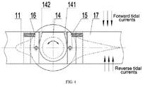
- FIG. 4 is a sectional view of FIG. 2 along A-A direction;
- FIG. 5 is a schematic diagram of a backswept blade of the tidal current generating unit of the present invention.
- FIG. 6 is a schematic diagram showing a blade pitch is changed to limit the blade of the tidal current generating unit of the present invention under a weak forward stream;
- FIG. 7 is a schematic diagram showing the blade pitch is changed to limit the tidal current generating unit of the present invention under a strong forward stream;
- FIG. 8 is a schematic diagram showing the blade pitch is changed to limit the blade of the tidal current generating unit of the present invention under a weak reverse stream;
- FIG. 9 is a schematic diagram showing the blade pitch is changed to limit the blade of the tidal current generating unit of the present invention under a strong reverse stream.
- FIG. 10 is a front view of a generator of the tidal current generating unit of the present invention.
- first”, “second”, and the like in the present invention are used for description only, and are not intended to indicate or imply their relative importance or the number of technical features, which explicitly or implicitly indicates that one or more features defined by “first” or “second” may be included in the present invention.
- the technical solutions of various embodiments may be combined to form other embodiments which are considered to fall within the claimed scope.
- connection may result in a fixed connection, a detachable connection, or an integrated configuration of elements.
- the elements may be connected mechanically or electrically; or directly connected or indirectly connected through an intermediate medium. Alternatively, two elements may be in communication or interact with each other unless specified.
- the specific meanings of the above terms in the present invention can be understood according to specific conditions.
- the tidal current generating unit of the present invention comprises a turbine 1 , a generator 2 , a bearing set (comprising a reverse thrust bearing 3 , a forward thrust bearing 4 , a front guide bearing 5 , and a rear guide bearing 6 ), a fixed dome 7 , a rotatable draft tube 8 and a fixed flange 9 ;
- the turbine 1 is directly connected to a rotor 22 of the generator 2 by the hub 17
- the rotor 22 is rotatably mounted on the outer circumference of a stator 21 of the generator 2 via the bearing set (comprising the reverse thrust bearing 3 , a forward thrust bearing 4 , a front guide bearing 5 , and a rear guide bearing 6 ), and the stator 21 is fixedly connected to the fixed flange 9 which fixes the tidal current generating unit 100 to an external carrier platform.
- a fixed dome 7 is fixedly mounted at the front end of the stator 21 to reduce the flow resistance
- a rotatable draft tube 8 is fixedly mounted on the outer circumference of the rotor 22 to reduce the flow resistance, and the rotatable draft tube 8 rotates with the turbine 1 and the rotor 22 .
- the turbine 1 comprises a blade 11 , a blade stem 12 , a blade stem bearing 13 , a pitch limiter 14 , a forward pitch regulator 15 , a reverse pitch regulator 16 and a hub 17 ;
- a root of the blade 11 is fixedly connected to the blade stem 12 ;
- a blade stem hole 171 is radially distributed on the hub 17
- the blade stem 12 is rotatably mounted in the blade stem hole 171 via the blade stem bearing 13 and is rotatable around the flange central axis of the blade 11 in the blade stem hole 171 ;
- a rear end of the blade stem 12 is connected to the pitch limiter 14 ; and an axial round hole 172 is provided on the center of the hub 17 and mounted with the front guide bearing 5 .
- the pitch limiter 14 comprises a first limiting edge 141 and a second limiting edge 142 which are protruding.
- the first and second limiting edges 141 , 142 surrounds the end of the blade stem 12 .
- the first limiting edge 141 cooperates with the forward pitch regulator 15 to limit the pitch angle of the blade 11 to a corresponding angle;
- the second limiting edge 142 cooperates with the reverse pitch regulator 16 to limit the pitch angle of the blade 11 to a corresponding angle.
- the blade 11 is a backswept blade and a hydrodynamic central axis 113 of the blade is inclined from a front edge 111 to a rear edge 112 by a first angle ⁇ from a flange central axis 114 of the blade 11 .
- the blade 11 is hollow and filled with a light filler 115 inside, such that the blade 11 has large buoyancy in the seawater due to the density of the blade 11 is much smaller than the density of the seawater to offset the gravity of the rotating component such as the hub 17 , the rotor 22 , etc., and thus the load of the front guide bearing 5 and a rear guide bearing 6 is greatly reduced.
- the blade 11 can be designed to have sufficient rather than excessive buoyancy in the seawater to offset the gravity of the rotating component.
- the forward pitch regulator 15 comprises a forward baffle 151 , a forward spring 153 and a forward pin 152 .
- the side of one end of the forward baffle 151 is connected to/abuts one end of the forward spring 153 , and the middle of the other end of the forward baffle 151 is rotatably mounted to the hub 17 by the forward pin 152 ; the forward baffle 151 is rotatable around the forward pin 152 ; and the other end of the forward spring 153 is connected to/abuts the hub 17 .
- the blade 11 , blade stem 12 and pitch limiter 14 are clockwise rotatable around the flange central axis 114 of the blade; the first limiting edge 141 is in contact with the forward baffle 151 so that a pressure is generated and transferred to the forward spring 153 , and the forward spring 153 is compressed and shortened; the forward baffle 151 is clockwise rotatable around the forward pin 152 ; and the pressure is eventually balanced by the reaction force of the forward spring 153 , so that the pitch angle of the blade 11 is changed and maintained at a forward angle ⁇ .
- the tidal energy captured by the turbine 1 rotates counterclockwise around the center of the turbine, so that the electricity is generated by directly driving the generator 2 .
- the tidal energy increases exponentially as the forward tidal current increases, and the energy captured by the turbine 1 also increases exponentially when the pitch angle of the blade 11 is remained at ⁇ , such that the generator is operated in an overload condition; at the same time, the pitch angle of the blade 11 increases automatically from ⁇ to ( ⁇ + ⁇ ) and the energy captured by the turbine 1 is reduced accordingly, which limits the overload of the generator and ensures a safe and reliable operation.
- the reverse pitch regulator 16 comprises a reverse baffle 161 , a reverse spring 163 , and a reverse pin 162 .
- the side of one end of the reverse baffle 161 is connected to/abuts one end of the reverse spring 163 and the middle of the other end of the reverse baffle 161 is rotatably mounted to the hub 17 by the reverse pin 162 , and the reverse baffle 161 is rotatable around the counter pin 162 , and the other end of the reverse spring 163 is connected to/abuts the hub 17 .
- the blade 11 , blade stem 12 and pitch limiter 14 are counterclockwise rotatable around the flange central axis 114 of the blade; the second limiting edge 142 is in contact with the reverse baffle 161 so that a pressure is generated and transferred to the reverse spring 163 , and the reverse spring 163 is compressed and shortened; the reverse baffle 161 is counterclockwise rotatable around the reverse pin 162 ; and the pressure is eventually balanced by the reaction force of the reverse spring 163 so that the pitch angle of the blade 11 is changed and maintained at a reverse angle ⁇ .
- the tidal energy captured by the turbine 1 rotates counterclockwise around the center of the turbine, so that the electricity is directly generated by driving the generator 2 .
- angle ⁇ is used to represent the forward angle ⁇ which is the pitch angle of the blade 11 and the reverse angle ⁇ which is the pitch angle of the blade 11 , but the values of the ⁇ may be different and varies according to the actions of the tidal currents. Similarly, the values of the forward angular rotation of ⁇ + ⁇ and the reverse angular rotation of ⁇ + ⁇ may also be different.
- the letters ⁇ is only illustrative and does not necessarily represent an equal value, and the value of ⁇ is determined by the material and structure of the components such as the forward pitch regulator 15 , the reverse pitch regulator 16 and the hub 17 , etc.
- the tidal energy increases exponentially as the reverse tidal current increases, and the energy captured by the turbine 1 also increases exponentially when the pitch angle of the blade 11 is remained at ⁇ , such that the generator is operated in an overload condition; at the same time, the pitch angle of the blade 11 is increased automatically from ⁇ to ( ⁇ + ⁇ ) and the energy captured by the turbine 1 is reduced accordingly, which limits the overload of the generator and ensures a safe and reliable operation.
- the adaptive mechanical structure of the turbine 1 of the above embodiment automatically adjusts the pitch, so the pitch angle of the blades is adjusted to limit the output power of the generator.
- the adaptive mechanical structure of the turbine 1 can be realized by the turbine comprising the blade stem, the blade stem bearing, the pitch limiter, the forward pitch regulator and the reverse pitch regulator, and it can also be realized by a deformable material or a designed mechanical structure that produces elastic deformations and recoveries from the deformation, so it is not limited herein.
- the generator 2 comprises the stator 21 and the rotor 22 ; the reverse thrust bearing 3 is mounted between a front end of central shaft 211 of the stator and the front bracket 221 of the rotor, and the forward thrust bearing 4 is mounted between a rear end of central shaft 211 of the stator and the rear bracket 222 of the rotor; an axial round hole is provided on the center of rear bracket 222 and mounted with a rear guide bearing 6 ; and sediment discharge holes 223 are provided on both ends of the rotor 22 to discharge the sediment outside the generator 2 , which prevents the generator 2 from the damages caused by the sediment deposition.
- the generator 2 is of an open structure without a sealed compartment, and no sealing member is required.
- the electrical surfaces of the stator 21 and the rotor 22 each are covered with a sealing layer 23 to ensure the electrical protection of the generator 2 .
- the seawater flows through the inside of the generator 2 , so that the heat is taken away to achieve the cooling effect.
- the unit capacity of the tidal current generating unit in the prior art has been developed to the megawatt level, but due to the sealed generator room, the sealing structure and heat dissipation of the generators have been a technical problem. However, the present invention overcomes such technical problem.
- the outer ring of the reverse thrust bearing 3 is provided with a sediment control ring 31 to prevent sediment from entering the reverse thrust bearing 3 ;
- the outer ring of the forward thrust bearing 4 is provided with a sediment control ring 41 to prevent the sediment from entering the forward thrust bearing 4 .
- the tidal current generating unit of the embodiment of the present invention is a horizontally arranged two-way passive direct-drive horizontal axis tidal current generating unit with a self-variable pitch.
- the tidal current generating unit of the embodiment of the present invention automatically changes the pitch under the forward or reverse tidal currents without relying on an external force such as a hydraulic pressure or electricity, and the tidal energy of the forward or reverse tidal current is captured by the blade 11 of the turbine 1 and the electricity is directly generated by driving the generator 2 ; when the flow rate of the tidal currents is higher than designed value and the generator is overloaded, the output power of the generator is limited by the automatic adjustment of the pitch, such that a safe and reliable operation of the generator is guaranteed.
- the generator is of the open structure with no requirement for sealing, and the heat of the generator is directly taken away by the seawater flowing through the inside of the generator, which overcomes the problems of sealing and heat dissipation of
Landscapes
- Engineering & Computer Science (AREA)
- Chemical & Material Sciences (AREA)
- Combustion & Propulsion (AREA)
- Mechanical Engineering (AREA)
- General Engineering & Computer Science (AREA)
- Life Sciences & Earth Sciences (AREA)
- General Life Sciences & Earth Sciences (AREA)
- Oceanography (AREA)
- Other Liquid Machine Or Engine Such As Wave Power Use (AREA)
Abstract
Description
Claims (9)
Applications Claiming Priority (2)
| Application Number | Priority Date | Filing Date | Title |
|---|---|---|---|
| CN201910958281.4 | 2019-10-10 | ||
| CN201910958281.4A CN110608128B (en) | 2019-10-10 | 2019-10-10 | Tidal current energy power generation device |
Publications (2)
| Publication Number | Publication Date |
|---|---|
| US20210108607A1 US20210108607A1 (en) | 2021-04-15 |
| US11028820B2 true US11028820B2 (en) | 2021-06-08 |
Family
ID=68894347
Family Applications (1)
| Application Number | Title | Priority Date | Filing Date |
|---|---|---|---|
| US16/688,330 Active US11028820B2 (en) | 2019-10-10 | 2019-11-19 | Tidal current generating unit |
Country Status (2)
| Country | Link |
|---|---|
| US (1) | US11028820B2 (en) |
| CN (1) | CN110608128B (en) |
Families Citing this family (9)
| Publication number | Priority date | Publication date | Assignee | Title |
|---|---|---|---|---|
| CN111156122B (en) * | 2020-01-08 | 2020-11-27 | 浙江大学 | A hydraulic direct-drive ocean current energy generator set pitch mechanism |
| CN112833144A (en) * | 2021-01-22 | 2021-05-25 | 南京高精船用设备有限公司 | A gear box for tidal power generation |
| CN113323792B (en) * | 2021-06-01 | 2022-08-19 | 湖南潇湘船舶有限公司 | Airflow pushing type blade rotating power generation equipment for ship |
| CN113279892B (en) * | 2021-06-04 | 2023-09-01 | 福建智盛能源科技有限公司 | Tidal current power generation device |
| CN113719401B (en) * | 2021-09-08 | 2023-06-30 | 东北石油大学 | Vertical rotary impeller type ocean tidal current energy power generation device |
| CN113915053B (en) * | 2021-10-13 | 2023-09-19 | 杭州江河水电科技股份有限公司 | Tidal current energy power generation device |
| GB2637454A (en) * | 2022-12-13 | 2025-07-30 | Hydrowing Ltd | Improvements in or relating to energy generation |
| GB202219606D0 (en) * | 2022-12-22 | 2023-02-08 | Proteus Marine Renewables Ltd | Passive pitch system |
| GB202408826D0 (en) * | 2024-06-19 | 2024-07-31 | Proteus Marine Renewables Ltd | Passive pitch system |
Citations (32)
| Publication number | Priority date | Publication date | Assignee | Title |
|---|---|---|---|---|
| US2080955A (en) * | 1936-10-22 | 1937-05-18 | Universal Battery Company | Propeller governor |
| US3582023A (en) * | 1969-07-23 | 1971-06-01 | Vlm Corp The | Pitch control for rotary wing aircraft |
| US3583828A (en) * | 1969-02-27 | 1971-06-08 | Garrett Corp | Compensated governor |
| US5005357A (en) * | 1990-07-09 | 1991-04-09 | Fox Mansel F | Oscillating force turbine |
| US5286166A (en) * | 1992-05-19 | 1994-02-15 | Steward Richard B | Automatic centrifugal force variable pitch propeller |
| US5599168A (en) * | 1995-08-23 | 1997-02-04 | Lund; Arnold M. | Wind turbine adaptable to wind direction and velocity |
| US6761533B2 (en) * | 2002-07-31 | 2004-07-13 | Natus Technology Corp. | Pitch governing assembly for windmills |
| US20080226450A1 (en) * | 2005-08-05 | 2008-09-18 | Joe Clarke | Turbine with Coaxial Sets of Blades |
| US20090004008A1 (en) * | 2007-06-28 | 2009-01-01 | Rolls-Royce Plc | Blade mounting |
| US20100001528A1 (en) * | 2008-06-06 | 2010-01-07 | Mark Kliewer | Underwater generator |
| US20100129215A1 (en) * | 2008-11-21 | 2010-05-27 | Preus Robert W | System for providing dynamic pitch control in a wind turbine |
| US20100226772A1 (en) * | 2009-02-25 | 2010-09-09 | Kenneth James Deering | Blade control system |
| US20100295309A1 (en) * | 2007-12-17 | 2010-11-25 | Benjamin Holstein | Submersible power generating plant, driven by a water flow |
| CN102230440A (en) | 2011-06-16 | 2011-11-02 | 中国海洋大学 | Bidirectional fairing and tidal current generating set |
| US20110272945A1 (en) * | 2010-05-07 | 2011-11-10 | Israel Ortiz | Ortiz turbine |
| US20120321466A1 (en) * | 2010-02-05 | 2012-12-20 | Rolls-Royce Plc | Bi directional water turbine |
| US20130026761A1 (en) * | 2011-07-27 | 2013-01-31 | Rajadhyaksha V V | Horizontal-axis hydrokinetic water turbine system |
| US20130045080A1 (en) * | 2010-04-18 | 2013-02-21 | Brian Kinloch Kirke | Cross flow wind or hydrokinetic turbines |
| US20130071240A1 (en) * | 2010-02-05 | 2013-03-21 | Rolls-Royce Plc | Bidirectional water turbine |
| US20130277980A1 (en) * | 2010-11-25 | 2013-10-24 | Kawasaki Jukogyo Kabushiki Kaisha | Water flow electricity generating device |
| US20130302169A1 (en) * | 2011-03-10 | 2013-11-14 | Voith Patent Gmbh | Rotor assembly for an axial turbine |
| US20140077772A1 (en) * | 2011-05-04 | 2014-03-20 | Rolls-Royce Plc | Turbine array and a method of controlling a turbine array during a loss-of-grid event |
| US20140284932A1 (en) * | 2011-08-09 | 2014-09-25 | University Of Southampton | Turbine generator |
| CN203978705U (en) | 2014-07-15 | 2014-12-03 | 杭州江河水电科技有限公司 | Single pile four impeller horizontal axis are passive from displacement bi-directional current generator set |
| US20150147172A1 (en) * | 2013-11-22 | 2015-05-28 | General Electric Company | System and method for preventing rotor blade tower strike |
| US20150284069A1 (en) * | 2012-11-06 | 2015-10-08 | Snecma | Device for controlling blade angle, and propeller |
| CN204783420U (en) | 2015-05-08 | 2015-11-18 | 沈阳风电设备发展有限责任公司 | High -efficient bidirectional flow horizontal axis can turbine blade from bending moment trend |
| US20170167465A1 (en) * | 2014-07-15 | 2017-06-15 | Okinawa Institute Of Science And Technology School Corporation | Wave energy converter |
| US20180230965A1 (en) * | 2015-08-13 | 2018-08-16 | Lm Wp Patent Holding A/S | Wind turbine blade provided with root end flange |
| CN108468614A (en) | 2018-05-29 | 2018-08-31 | 江苏科技大学 | A kind of double turbine tidal current energy generating equipments of NEW ADAPTIVE tidal range |
| US20200056584A1 (en) * | 2018-08-20 | 2020-02-20 | Yik Hei Sia | Power generating windbags and waterbags |
| US20200132041A1 (en) * | 2018-10-30 | 2020-04-30 | Hangzhou Jianghe Hydro-Electrical Science& Technology Co., Ltd. | Ducted bidirectional tidal current power station system |
Family Cites Families (7)
| Publication number | Priority date | Publication date | Assignee | Title |
|---|---|---|---|---|
| CN201011335Y (en) * | 2006-08-03 | 2008-01-23 | 陕西新通智能科技有限公司 | Self-adapting torsional spring velocity regulating aerogenerator |
| CN201874748U (en) * | 2010-11-30 | 2011-06-22 | 窦忠义 | Centrifugal speed-regulating pitch variable mechanism of wind driven generator |
| CN102251902A (en) * | 2011-06-20 | 2011-11-23 | 中国海洋大学 | Variable-propeller-pitch water turbine and tide generating device |
| FR2983535B1 (en) * | 2011-12-01 | 2018-10-19 | Alstom Renewable Technologies | TURBINE |
| CN103397980A (en) * | 2013-08-02 | 2013-11-20 | 中国海洋石油总公司 | Variable-pitch mechanism of tidal current energy electricity generation water turbine |
| CN104481790A (en) * | 2014-11-20 | 2015-04-01 | 哈尔滨工程大学 | Direct drive independent variable pitch tidal current energy electric generation hydraulic turbine |
| CN109185009B (en) * | 2018-09-07 | 2020-05-08 | 杭州江河水电科技有限公司 | Passive self-adaptive reciprocating bidirectional water flow impeller device |
-
2019
- 2019-10-10 CN CN201910958281.4A patent/CN110608128B/en active Active
- 2019-11-19 US US16/688,330 patent/US11028820B2/en active Active
Patent Citations (32)
| Publication number | Priority date | Publication date | Assignee | Title |
|---|---|---|---|---|
| US2080955A (en) * | 1936-10-22 | 1937-05-18 | Universal Battery Company | Propeller governor |
| US3583828A (en) * | 1969-02-27 | 1971-06-08 | Garrett Corp | Compensated governor |
| US3582023A (en) * | 1969-07-23 | 1971-06-01 | Vlm Corp The | Pitch control for rotary wing aircraft |
| US5005357A (en) * | 1990-07-09 | 1991-04-09 | Fox Mansel F | Oscillating force turbine |
| US5286166A (en) * | 1992-05-19 | 1994-02-15 | Steward Richard B | Automatic centrifugal force variable pitch propeller |
| US5599168A (en) * | 1995-08-23 | 1997-02-04 | Lund; Arnold M. | Wind turbine adaptable to wind direction and velocity |
| US6761533B2 (en) * | 2002-07-31 | 2004-07-13 | Natus Technology Corp. | Pitch governing assembly for windmills |
| US20080226450A1 (en) * | 2005-08-05 | 2008-09-18 | Joe Clarke | Turbine with Coaxial Sets of Blades |
| US20090004008A1 (en) * | 2007-06-28 | 2009-01-01 | Rolls-Royce Plc | Blade mounting |
| US20100295309A1 (en) * | 2007-12-17 | 2010-11-25 | Benjamin Holstein | Submersible power generating plant, driven by a water flow |
| US20100001528A1 (en) * | 2008-06-06 | 2010-01-07 | Mark Kliewer | Underwater generator |
| US20100129215A1 (en) * | 2008-11-21 | 2010-05-27 | Preus Robert W | System for providing dynamic pitch control in a wind turbine |
| US20100226772A1 (en) * | 2009-02-25 | 2010-09-09 | Kenneth James Deering | Blade control system |
| US20120321466A1 (en) * | 2010-02-05 | 2012-12-20 | Rolls-Royce Plc | Bi directional water turbine |
| US20130071240A1 (en) * | 2010-02-05 | 2013-03-21 | Rolls-Royce Plc | Bidirectional water turbine |
| US20130045080A1 (en) * | 2010-04-18 | 2013-02-21 | Brian Kinloch Kirke | Cross flow wind or hydrokinetic turbines |
| US20110272945A1 (en) * | 2010-05-07 | 2011-11-10 | Israel Ortiz | Ortiz turbine |
| US20130277980A1 (en) * | 2010-11-25 | 2013-10-24 | Kawasaki Jukogyo Kabushiki Kaisha | Water flow electricity generating device |
| US20130302169A1 (en) * | 2011-03-10 | 2013-11-14 | Voith Patent Gmbh | Rotor assembly for an axial turbine |
| US20140077772A1 (en) * | 2011-05-04 | 2014-03-20 | Rolls-Royce Plc | Turbine array and a method of controlling a turbine array during a loss-of-grid event |
| CN102230440A (en) | 2011-06-16 | 2011-11-02 | 中国海洋大学 | Bidirectional fairing and tidal current generating set |
| US20130026761A1 (en) * | 2011-07-27 | 2013-01-31 | Rajadhyaksha V V | Horizontal-axis hydrokinetic water turbine system |
| US20140284932A1 (en) * | 2011-08-09 | 2014-09-25 | University Of Southampton | Turbine generator |
| US20150284069A1 (en) * | 2012-11-06 | 2015-10-08 | Snecma | Device for controlling blade angle, and propeller |
| US20150147172A1 (en) * | 2013-11-22 | 2015-05-28 | General Electric Company | System and method for preventing rotor blade tower strike |
| CN203978705U (en) | 2014-07-15 | 2014-12-03 | 杭州江河水电科技有限公司 | Single pile four impeller horizontal axis are passive from displacement bi-directional current generator set |
| US20170167465A1 (en) * | 2014-07-15 | 2017-06-15 | Okinawa Institute Of Science And Technology School Corporation | Wave energy converter |
| CN204783420U (en) | 2015-05-08 | 2015-11-18 | 沈阳风电设备发展有限责任公司 | High -efficient bidirectional flow horizontal axis can turbine blade from bending moment trend |
| US20180230965A1 (en) * | 2015-08-13 | 2018-08-16 | Lm Wp Patent Holding A/S | Wind turbine blade provided with root end flange |
| CN108468614A (en) | 2018-05-29 | 2018-08-31 | 江苏科技大学 | A kind of double turbine tidal current energy generating equipments of NEW ADAPTIVE tidal range |
| US20200056584A1 (en) * | 2018-08-20 | 2020-02-20 | Yik Hei Sia | Power generating windbags and waterbags |
| US20200132041A1 (en) * | 2018-10-30 | 2020-04-30 | Hangzhou Jianghe Hydro-Electrical Science& Technology Co., Ltd. | Ducted bidirectional tidal current power station system |
Also Published As
| Publication number | Publication date |
|---|---|
| CN110608128B (en) | 2021-03-30 |
| CN110608128A (en) | 2019-12-24 |
| US20210108607A1 (en) | 2021-04-15 |
Similar Documents
| Publication | Publication Date | Title |
|---|---|---|
| US11028820B2 (en) | Tidal current generating unit | |
| EP2195524B1 (en) | Device for converting kinetic energy of a flowing water into kinetic energy of a rotatable rotor shaft | |
| CN103511171B (en) | A kind of control method of tidal current energy generating equipment | |
| JP2013528737A (en) | Unidirectional hydroturbine with reinforced ducts, blades and generator | |
| JP2008538597A (en) | Rotor system tension wheel for wind and hydro turbines | |
| CN106286122A (en) | A kind of band bilayer lift strengthens and rises the vertical axis windmill hindering automatic switching foil | |
| CN110617182A (en) | Magnetic suspension wind generating set | |
| CN106438184B (en) | The flexible blade of the automatic variable pitch turbine of hydrodynamic force | |
| CN101798983B (en) | Special turbine for self-variable-pitch bidirectional-flow ocean current power station | |
| CN103758688A (en) | Horizontal axis tidal energy turbine yaw adjustment device | |
| CN105065189B (en) | It is a kind of from convection type horizontal axis tidal current energy TRT | |
| CN109185009B (en) | Passive self-adaptive reciprocating bidirectional water flow impeller device | |
| JP3195023U (en) | Means for improving the conversion ratio of wind energy to electric energy in a vertical axis wind turbine generator with flywheel having drag type blades (blades) (shown in FIG. 2 and hereinafter referred to as the vertical axis wind turbine generator) | |
| CN102384020A (en) | Horizontal shaft pitch-control tide energy water turbine | |
| US11885292B2 (en) | Tidal current energy generating device | |
| JP7714228B2 (en) | Water current power generation device | |
| CN105134478A (en) | Rectifying wind generator set and manufacturing method thereof | |
| CN108798971A (en) | A kind of adaptive water conservancy diversion accelerator for horizontal shaft water-turbine | |
| CN211852043U (en) | Integrated tidal current energy power generation device and tidal current energy unit comprising same | |
| CN109519322A (en) | A kind of eccentric inertia wheel formula generation platform | |
| KR20170046985A (en) | hydraulic power generator | |
| GB2433554A (en) | Transverse axis wind or water turbine | |
| KR100622629B1 (en) | Opening and closing door type turbine with vertical shaft and many wings for generating power using the flow of fluid | |
| JP6398095B2 (en) | Power equipment | |
| US20190293047A1 (en) | Fluid machine and power generation device |
Legal Events
| Date | Code | Title | Description |
|---|---|---|---|
| FEPP | Fee payment procedure |
Free format text: ENTITY STATUS SET TO UNDISCOUNTED (ORIGINAL EVENT CODE: BIG.); ENTITY STATUS OF PATENT OWNER: SMALL ENTITY |
|
| FEPP | Fee payment procedure |
Free format text: ENTITY STATUS SET TO SMALL (ORIGINAL EVENT CODE: SMAL); ENTITY STATUS OF PATENT OWNER: SMALL ENTITY |
|
| STPP | Information on status: patent application and granting procedure in general |
Free format text: NOTICE OF ALLOWANCE MAILED -- APPLICATION RECEIVED IN OFFICE OF PUBLICATIONS |
|
| AS | Assignment |
Owner name: HANGZHOU JIANGHE HYDRO-ELECTRICAL SCIENCE&TECHNOLOGY CO., LTD., CHINA Free format text: ASSIGNMENT OF ASSIGNORS INTEREST;ASSIGNORS:LIU, CHANGLU;CHEN, LIWEI;ZHOU, ZHENGMING;AND OTHERS;REEL/FRAME:056108/0361 Effective date: 20191114 |
|
| STPP | Information on status: patent application and granting procedure in general |
Free format text: PUBLICATIONS -- ISSUE FEE PAYMENT RECEIVED |
|
| STPP | Information on status: patent application and granting procedure in general |
Free format text: PUBLICATIONS -- ISSUE FEE PAYMENT VERIFIED |
|
| STCF | Information on status: patent grant |
Free format text: PATENTED CASE |
|
| CC | Certificate of correction | ||
| MAFP | Maintenance fee payment |
Free format text: PAYMENT OF MAINTENANCE FEE, 4TH YR, SMALL ENTITY (ORIGINAL EVENT CODE: M2551); ENTITY STATUS OF PATENT OWNER: SMALL ENTITY Year of fee payment: 4 |