US11027182B2 - Sports equipment for functional training - Google Patents
Sports equipment for functional training Download PDFInfo
- Publication number
- US11027182B2 US11027182B2 US16/325,565 US201716325565A US11027182B2 US 11027182 B2 US11027182 B2 US 11027182B2 US 201716325565 A US201716325565 A US 201716325565A US 11027182 B2 US11027182 B2 US 11027182B2
- Authority
- US
- United States
- Prior art keywords
- handle
- sports equipment
- stem
- equipment according
- weight
- Prior art date
- Legal status (The legal status is an assumption and is not a legal conclusion. Google has not performed a legal analysis and makes no representation as to the accuracy of the status listed.)
- Active
Links
- 239000000463 material Substances 0.000 claims abstract description 11
- 230000008878 coupling Effects 0.000 claims description 10
- 238000010168 coupling process Methods 0.000 claims description 10
- 238000005859 coupling reaction Methods 0.000 claims description 10
- 239000007779 soft material Substances 0.000 claims description 6
- 230000001133 acceleration Effects 0.000 claims description 2
- 230000033001 locomotion Effects 0.000 description 13
- XEEYBQQBJWHFJM-UHFFFAOYSA-N Iron Chemical compound [Fe] XEEYBQQBJWHFJM-UHFFFAOYSA-N 0.000 description 4
- 238000004026 adhesive bonding Methods 0.000 description 4
- 210000003205 muscle Anatomy 0.000 description 3
- 230000005540 biological transmission Effects 0.000 description 2
- 229910052742 iron Inorganic materials 0.000 description 2
- 238000004080 punching Methods 0.000 description 2
- 241000345998 Calamus manan Species 0.000 description 1
- 230000000694 effects Effects 0.000 description 1
- 239000011888 foil Substances 0.000 description 1
- 230000003116 impacting effect Effects 0.000 description 1
- 238000000034 method Methods 0.000 description 1
- 230000036314 physical performance Effects 0.000 description 1
- 235000012950 rattan cane Nutrition 0.000 description 1
- 238000004088 simulation Methods 0.000 description 1
- 125000006850 spacer group Chemical group 0.000 description 1
Images


Classifications
-
- A63B69/004—
-
- A—HUMAN NECESSITIES
- A63—SPORTS; GAMES; AMUSEMENTS
- A63B—APPARATUS FOR PHYSICAL TRAINING, GYMNASTICS, SWIMMING, CLIMBING, OR FENCING; BALL GAMES; TRAINING EQUIPMENT
- A63B23/00—Exercising apparatus specially adapted for particular parts of the body
- A63B23/035—Exercising apparatus specially adapted for particular parts of the body for limbs, i.e. upper or lower limbs, e.g. simultaneously
-
- A—HUMAN NECESSITIES
- A63—SPORTS; GAMES; AMUSEMENTS
- A63B—APPARATUS FOR PHYSICAL TRAINING, GYMNASTICS, SWIMMING, CLIMBING, OR FENCING; BALL GAMES; TRAINING EQUIPMENT
- A63B15/00—Clubs for gymnastics or the like, e.g. for swinging exercises
-
- A—HUMAN NECESSITIES
- A63—SPORTS; GAMES; AMUSEMENTS
- A63B—APPARATUS FOR PHYSICAL TRAINING, GYMNASTICS, SWIMMING, CLIMBING, OR FENCING; BALL GAMES; TRAINING EQUIPMENT
- A63B21/00—Exercising apparatus for developing or strengthening the muscles or joints of the body by working against a counterforce, with or without measuring devices
- A63B21/06—User-manipulated weights
- A63B21/072—Dumb-bells, bar-bells or the like, e.g. weight discs having an integral peripheral handle
- A63B21/075—Dumb-bells, bar-bells or the like, e.g. weight discs having an integral peripheral handle with variable weights, e.g. weight systems with weight selecting means for bar-bells or dumb-bells
-
- A—HUMAN NECESSITIES
- A63—SPORTS; GAMES; AMUSEMENTS
- A63B—APPARATUS FOR PHYSICAL TRAINING, GYMNASTICS, SWIMMING, CLIMBING, OR FENCING; BALL GAMES; TRAINING EQUIPMENT
- A63B23/00—Exercising apparatus specially adapted for particular parts of the body
- A63B23/035—Exercising apparatus specially adapted for particular parts of the body for limbs, i.e. upper or lower limbs, e.g. simultaneously
- A63B23/03508—For a single arm or leg
-
- A—HUMAN NECESSITIES
- A63—SPORTS; GAMES; AMUSEMENTS
- A63B—APPARATUS FOR PHYSICAL TRAINING, GYMNASTICS, SWIMMING, CLIMBING, OR FENCING; BALL GAMES; TRAINING EQUIPMENT
- A63B23/00—Exercising apparatus specially adapted for particular parts of the body
- A63B23/035—Exercising apparatus specially adapted for particular parts of the body for limbs, i.e. upper or lower limbs, e.g. simultaneously
- A63B23/12—Exercising apparatus specially adapted for particular parts of the body for limbs, i.e. upper or lower limbs, e.g. simultaneously for upper limbs or related muscles, e.g. chest, upper back or shoulder muscles
- A63B23/1209—Involving a bending of elbow and shoulder joints simultaneously
-
- A—HUMAN NECESSITIES
- A63—SPORTS; GAMES; AMUSEMENTS
- A63B—APPARATUS FOR PHYSICAL TRAINING, GYMNASTICS, SWIMMING, CLIMBING, OR FENCING; BALL GAMES; TRAINING EQUIPMENT
- A63B60/00—Details or accessories of golf clubs, bats, rackets or the like
- A63B60/06—Handles
- A63B60/22—Adjustable handles
- A63B60/24—Weighted handles
-
- A—HUMAN NECESSITIES
- A63—SPORTS; GAMES; AMUSEMENTS
- A63B—APPARATUS FOR PHYSICAL TRAINING, GYMNASTICS, SWIMMING, CLIMBING, OR FENCING; BALL GAMES; TRAINING EQUIPMENT
- A63B69/00—Training appliances or apparatus for special sports
-
- A—HUMAN NECESSITIES
- A63—SPORTS; GAMES; AMUSEMENTS
- A63B—APPARATUS FOR PHYSICAL TRAINING, GYMNASTICS, SWIMMING, CLIMBING, OR FENCING; BALL GAMES; TRAINING EQUIPMENT
- A63B71/00—Games or sports accessories not covered in groups A63B1/00 - A63B69/00
- A63B71/06—Indicating or scoring devices for games or players, or for other sports activities
- A63B71/0619—Displays, user interfaces and indicating devices, specially adapted for sport equipment, e.g. display mounted on treadmills
- A63B71/0622—Visual, audio or audio-visual systems for entertaining, instructing or motivating the user
-
- A63B2069/0044—
-
- A—HUMAN NECESSITIES
- A63—SPORTS; GAMES; AMUSEMENTS
- A63B—APPARATUS FOR PHYSICAL TRAINING, GYMNASTICS, SWIMMING, CLIMBING, OR FENCING; BALL GAMES; TRAINING EQUIPMENT
- A63B2220/00—Measuring of physical parameters relating to sporting activity
- A63B2220/17—Counting, e.g. counting periodical movements, revolutions or cycles, or including further data processing to determine distances or speed
-
- A—HUMAN NECESSITIES
- A63—SPORTS; GAMES; AMUSEMENTS
- A63B—APPARATUS FOR PHYSICAL TRAINING, GYMNASTICS, SWIMMING, CLIMBING, OR FENCING; BALL GAMES; TRAINING EQUIPMENT
- A63B2220/00—Measuring of physical parameters relating to sporting activity
- A63B2220/30—Speed
-
- A—HUMAN NECESSITIES
- A63—SPORTS; GAMES; AMUSEMENTS
- A63B—APPARATUS FOR PHYSICAL TRAINING, GYMNASTICS, SWIMMING, CLIMBING, OR FENCING; BALL GAMES; TRAINING EQUIPMENT
- A63B2220/00—Measuring of physical parameters relating to sporting activity
- A63B2220/40—Acceleration
-
- A—HUMAN NECESSITIES
- A63—SPORTS; GAMES; AMUSEMENTS
- A63B—APPARATUS FOR PHYSICAL TRAINING, GYMNASTICS, SWIMMING, CLIMBING, OR FENCING; BALL GAMES; TRAINING EQUIPMENT
- A63B2220/00—Measuring of physical parameters relating to sporting activity
- A63B2220/50—Force related parameters
- A63B2220/51—Force
- A63B2220/53—Force of an impact, e.g. blow or punch
-
- A—HUMAN NECESSITIES
- A63—SPORTS; GAMES; AMUSEMENTS
- A63B—APPARATUS FOR PHYSICAL TRAINING, GYMNASTICS, SWIMMING, CLIMBING, OR FENCING; BALL GAMES; TRAINING EQUIPMENT
- A63B2220/00—Measuring of physical parameters relating to sporting activity
- A63B2220/80—Special sensors, transducers or devices therefor
- A63B2220/83—Special sensors, transducers or devices therefor characterised by the position of the sensor
- A63B2220/833—Sensors arranged on the exercise apparatus or sports implement
-
- A—HUMAN NECESSITIES
- A63—SPORTS; GAMES; AMUSEMENTS
- A63B—APPARATUS FOR PHYSICAL TRAINING, GYMNASTICS, SWIMMING, CLIMBING, OR FENCING; BALL GAMES; TRAINING EQUIPMENT
- A63B2225/00—Miscellaneous features of sport apparatus, devices or equipment
- A63B2225/50—Wireless data transmission, e.g. by radio transmitters or telemetry
-
- A—HUMAN NECESSITIES
- A63—SPORTS; GAMES; AMUSEMENTS
- A63B—APPARATUS FOR PHYSICAL TRAINING, GYMNASTICS, SWIMMING, CLIMBING, OR FENCING; BALL GAMES; TRAINING EQUIPMENT
- A63B2225/00—Miscellaneous features of sport apparatus, devices or equipment
- A63B2225/62—Inflatable
-
- A—HUMAN NECESSITIES
- A63—SPORTS; GAMES; AMUSEMENTS
- A63B—APPARATUS FOR PHYSICAL TRAINING, GYMNASTICS, SWIMMING, CLIMBING, OR FENCING; BALL GAMES; TRAINING EQUIPMENT
- A63B2230/00—Measuring physiological parameters of the user
- A63B2230/75—Measuring physiological parameters of the user calorie expenditure
-
- A—HUMAN NECESSITIES
- A63—SPORTS; GAMES; AMUSEMENTS
- A63B—APPARATUS FOR PHYSICAL TRAINING, GYMNASTICS, SWIMMING, CLIMBING, OR FENCING; BALL GAMES; TRAINING EQUIPMENT
- A63B23/00—Exercising apparatus specially adapted for particular parts of the body
- A63B23/035—Exercising apparatus specially adapted for particular parts of the body for limbs, i.e. upper or lower limbs, e.g. simultaneously
- A63B23/03516—For both arms together or both legs together; Aspects related to the co-ordination between right and left side limbs of a user
- A63B23/03525—Supports for both feet or both hands performing simultaneously the same movement, e.g. single pedal or single handle
-
- A—HUMAN NECESSITIES
- A63—SPORTS; GAMES; AMUSEMENTS
- A63B—APPARATUS FOR PHYSICAL TRAINING, GYMNASTICS, SWIMMING, CLIMBING, OR FENCING; BALL GAMES; TRAINING EQUIPMENT
- A63B69/00—Training appliances or apparatus for special sports
- A63B69/333—Fake or disarmed practise weapons, i.e. for mimicking combat situations in martial arts training
Definitions
- the present invention is related to a sports equipment of the type including a handle to which a stem is fixed.
- Foil, swords and sabres are known in the art as sports equipments used in competition between two contenders. Such equipments are normally light so as to enable a quick and accurate movement: their weigh is usually comprised between 500 and 700 grams distributed in an almost balanced fashion between the handle and the stem.
- U.S. Pat. No. 660,692 shows a dump-bell which, in a use configuration, has a handling part from which a rigid threaded stem projects.
- the handle can be used as a conventional dump-bell or as a club for juggling exercises.
- U.S. Pat. No. 5,180,164 discloses a light police baton with a handle to which a stick made up of a light rattan core is fixed.
- the baton is intended to be used by law enforcement officers to deliver minor damages to the ill-intentioned thanks to its overall lightness.
- the object of the invention is to provide a sports equipment thus made.
- a sports equipment i.e. comprising a handle having a first end and a second end, at least one stem made of soft and light material aligned to said handle and fixed at the first end, and in which the weight of the handle is considerably greater than that of the stem.
- the invention provides for a sports kit made up of the sports equipment used alongside a shield which comprises a disc-shaped structure having an inner face to which a handle is fixed and an outer face provided with a soft material lining, in which the disc-shaped structure is suitable to fixedly or removably house one or more variable weight elements.
- a sports training method in which the sports equipment and the shield can be used simultaneously is also described.
- using the sports equipment and/or the shield according to the invention enables performing a sports activity aimed at making countless more or less complex movements (or combinations of movements), individually, in pairs or in groups, thanks to the greater weight of the handle of the equipment and the structure of the shield (if provided), performing a physical training exercise for building up muscles and simultaneously, thanks to the soft and light stem of the sports equipment, making the action against an object (or person) entirely harmless.
- FIG. 1 schematically shows the distribution of the masses in a conventional equipment ( FIG. 1.1 ) and in one according to the invention ( FIG. 1.2 );
- FIG. 2 shows a conventionally known tool ( FIG. 2.1 ) and sports equipment ( FIG. 2.2 ) and some embodiments of the invention ( FIGS. 2.3-2.11 );
- FIGS. 3 to 5 show some possible embodiments of the sports equipment according to the invention.
- FIG. 6 shows an embodiment of the equipment providing for a modular solution for applying gym weights to the handle
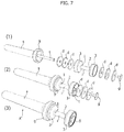
- FIG. 7 shows a variant of the sports equipment of FIG. 6 ;
- FIG. 8 shows an embodiment of the equipment that enables adding weights on the second end of the handle
- FIG. 9 shows an exploded view of an embodiment of the sports equipment according to the invention, comprising an electronic module provided with sensors and means for the remote transmission of the data detected by the sensors;
- FIG. 10 shows a shield of a kit according to the invention
- FIG. 11 shows a sports equipment provided with two stems according to a variant of the invention.
- FIGS. 12 to 14 show possible examples of use of the sports equipment according to the invention.
- FIG. 15 shows a potential use of the sports kit made up of the equipment and the shield according to the invention.
- FIG. 1 shows the principles of the invention with reference to an elementary object made up of an extended stem and a head in two different use configurations.
- the distribution of masses in the two different configurations with respect to the part in which the object is held by a user are represented schematically.
- the mass stem m serves as a handle and the mass head M is moved at speed v.
- the mass stem m is moved at speed v and the mass head M serves as a handle.
- the amount of motion P 1 Mv associated to the mass head M of the object in the use configuration of FIG.
- FIG. 2 illustrates a conventional hammer ( FIG. 2.1 ) and a conventional sword ( FIGS. 2.2 ) and three embodiments of the invention ( FIGS. 2.3, 2.4, 2.5 ) with the aim of revealing the physics principle described with reference to FIG. 1 .
- the hammer illustrated in FIG. 2.1 has a head T with considerably greater mass with respect to the handle im. Also the sword in FIG. 2.2 has a blade L with a considerably greater mass with respect to the handle ip. With the aim of optimising the purpose that these objects were designed for, it is actually preferable that the amount of motion transmitted to the object to be impacted by means of the opposite end with respect to handle be the greatest possible (same principle also applying to a baseball bat, golf club or the like).
- the article of the example illustrated in FIG. 1.2 refers to a sports equipment A according to the invention, which is shown in some embodiments thereof in FIGS. 2.3-2.11 in which the equipment A has a handle i having a considerably greater mass than the mass of the stem s.
- the amount of motion transmitted to the object or person hit by the stem s is reduced to the minimum and, at the same time, due to the heavy handle i, a user may perform a considerable physical exercise suitable to build muscles and improve strength, resistance and coordination physical performance.
- the weight of said handle i is one order of magnitude greater than that of the stem s.
- the heavy handle i is designed to enable a comfortable and firm grip with one hand or, in an embodiment, with two hands.
- it can be variously shaped: in FIG. 2.3 the handle i is shaped to form a constant radius cylinder, while in FIGS. 2.4, 2.5, 2.6 and 2.7 it has one or two disc-shaped elements or flanges 3 projecting from one or both ends 1 , 2 .
- the projecting disc-shaped elements 3 have the double function of increasing the weight of the element on which they are mounted and protecting the hand when the element is placed on the ground.
- the flange projecting from the end 2 is shaped without edges and in FIGS.
- the diameter of the handle i is comprised between 10 and 60 mm, more preferably approximately between 30 and 40 mm.
- the weight of the handle i may be comprised approximately between 1 kg and 10 kg.
- the stem s is designed to be as light as possible, so that the amount of motion transmitted during an impact is minimum. In addition, it is made of soft material, so that the force resulting from the impact is minimised further.
- An example of material suitable for constructing the stem is XL EXTRALIGHT®, a closed-cell expanded material sold in Italy by Finproject S.p.A. Thanks to these characteristics, the action of the sports equipment A on an hit object or person will be of low impact and thus entirely harmless.
- the stem s in the area for coupling with the handle, has a protection-like flange 9 covered with soft material to partly protect the hand of a user and prevent the hit object or person from impacting against a part made of hard material.
- the length of the stem s is approximately comprised between 20 and 100 cm, more preferably between 30 and 80 cm; as mentioned, the weight of the stem s is considerably lesser than that of the handle i and preferably lesser than 1 Kg approximately.
- the heavy handle i and the light stem s are aligned on the same axis and are integrally mutually joined so as not to disengage during use. In some embodiments, the engagement between the stem s and the handle i is permanent, while it is releasable in others so as to enable disassembly thereof.
- the stem s is constituted by an inflatable bladder.
- FIG. 3 shows some embodiments of the equipment A according to the invention.
- FIG. 3.1 the fixing of the stem s on the handle i is obtained by gluing or coupling so as to obtain the assembled equipment A of FIG. 3.2 ;
- the stem is provided with an inner stiffening core 4 that can be coupled to the handle i by means of screws or coupling so as to obtain the assembled equipment A of FIG. 3.4 ;
- the handle i is provided with a pipe t projecting from the first end 1 thereof and couplable to the stem s by means of gluing or coupling so as to obtain the assembly A of FIG. 3.6 ;
- FIG. 3.7 shows an exploded view of an embodiment according to the invention in which the pipe t is suitable to be partly introduced and locked by gluing or coupling in the stem s.
- a hollow cylindrical handle i provided with an end flange 3 , is provided with a coaxial through hole 8 within which the portion of the pipe t projecting from the stem s can be inserted.
- Screw-like fastening members v are designed to fix the end of the portion of the pipe t projecting from the stem s to the second end 2 of the handle 1 so as to obtain the assembly A of FIG. 3.8 .
- the handle can be constituted by a cylinder made of plastic and/or rubber material with end flanges 3 within which one or more suitably calibrated weights (for example made of iron or lead) can be permanently or removably housed.
- the handle i and the flange 3 can be made of one or more heavy materials (for example iron or lead) and be partly or fully covered by soft material.
- FIG. 4 shows some possible variants of the handle i of the equipment A according to the invention.
- the handles i have respectively increasing dimensions and weights
- FIG. 5 shows some possible variants of the stem s of the equipment A according to the invention:
- the stem s has a variable diameter section in the area for coupling with the handle i and/or in the opposite end;
- the stems s have similar shapes and different lengths.
- FIG. 6 shows an embodiment of the equipment A according to the invention which enables obtaining a disassemblable modular solution to enable quick assembly and disassembly of one or more commonly known gym weights d.
- FIG. 6.1 shows an exploded view of the entirety of the components.
- the stem s is designed with an annular flange 9 in the end for coupling with the handle i.
- the handle i comprises a tubular section t which is coupled to the stem in a first end thereof by means of gluing and/or coupling, and it is provided with a thread 10 in the opposite end thereof.
- the following are engaged on the pipe t in the following order: two gym weights d to be arranged abutting against the flange of the stem 9 , a hollow cylindrical knob m which also serves as a spacer between the weights d, two further gym weights d and a threaded ring nut v that can be engaged in the thread 10 and suitable to firmly lock the weights d and the knob m on the pipe t;
- FIG. 6.2 shows the end result with the assembly A.
- FIG. 7 shows an embodiment of the equipment A according to the invention similar to the one described in FIG. 6 .
- the hollow knob m includes, at each of the ends thereof, two flanges 3 in which weights d of different dimensions and/or materials can be housed.
- FIG. 7.1 shows an exploded view of the components used in this embodiment.
- FIG. 7.2 shows, in partially exploded view, an intermediate assembly condition in which three weights d abut against the end flange 9 of the stem s and they are housed in the corresponding end flange 3 of the handle i. Other three weights d can once again be engaged on the pipe t, housed in the end flange 3 and fastened using the ring nut g.
- FIG. 7.3 shows the end result with the assembly A.
- the number and amount of weights d used may vary unlimitedly.
- FIG. 8 shows a further embodiment of the equipment A according to the invention.
- FIG. 8.1 shows a cylindrical-shaped weight 11 that can be fixed at a hole f provided on the second end 2 of the handle i by means of a screw or coupling system.
- FIG. 8.2 shows the end result with the assembly A.
- the weight 11 may vary in terms of shape and material to enable simply and practically modifying the overall weight of the sports equipment A.
- FIG. 9 shows an embodiment of the equipment A according to the invention which enables housing an electronic module provided with sensors for measuring the performance level during training.
- sensors for measuring the performance level during training.
- Such sensors are suitable to calculate acceleration, speed, delivered shots and the calories used by a user during a training session.
- Wi-Fi or Bluetooth means for the remote transmission of the data detected by the sensors to an external receiver device (for example a smartphone or tablets, not shown) on which there can be operated a specific application for processing and displaying such data, are also provided for.
- the electronic module e can be inserted into a hole f of the handle i and be locked by means of a ring nut g. Alternatively, the electronic module can be housed outside the handle.
- FIG. 10 shows a shield 12 which forms a sports kit according to the invention alongside the previously described equipment A.
- FIG. 10.1 shows an exploded view of the elements that form the shield 12 .
- the shield 12 comprises a disc-shaped structure 4 having an inner face 5 to which a handle 6 and an outer face 7 provided with a soft material lining, is fixed.
- the disc-shaped structure 4 is suitable to fixedly or removably house one or more variable weight elements d.
- FIG. 10.2 shows the end result with the assembly 12 .
- FIG. 11 shows a variant of the equipment A according to the invention provided with two juxtaposed stems s, s.
- a respective stem s is connected to each end 1 , 2 of the handle i as described in any of the previous embodiments.
- FIG. 12 shows a potential example of use of the equipment according to the invention.
- FIG. 12.1 shows a person p gripping the equipment A and training following roto-translational movements schematised by the double arrow rt; there are countless possible movements for simulating the conditions typical of a sword battle; training can be carried out by repeating the movements (or combinations of movements) in subsequent series that provide for various repetitions; training can be carried out with or without music.
- FIG. 12.2 shows several people p 1 , p 2 , p 3 respectively gripping the sports equipment A 1 , A 2 , A 3 and training executing-together and in a coordinated fashion-several types of movements like in the case of FIG. 12.1 .
- FIG. 13 shows a potential example of application of the equipment according to the invention.
- FIG. 13.1 shows a person p gripping the equipment A and training hitting a punching bag b hanged on the ceiling;
- FIG. 13.2 shows a person p gripping the equipment A and training hitting a punching bag b placed on the ground.
- FIG. 14 shows a potential example of use of the equipment A according to the invention.
- FIG. 14.1 shows two people p 1 and p 2 , respectively gripping the sports equipment A 1 and A 2 , training simulating moves similar to a sword battle.
- FIG. 14.2 shows two people p 1 and p 2 , gripping two sports equipment respectively A 1 -A 2 and A 3 -A 4 , training simulating moves similar to a sword battle.
- FIG. 15 shows a potential example of application and use of the sports kit according to the invention.
- FIG. 15.1 shows a person p 1 gripping an equipment having a handle with two hands A 1 and training with a person p 2 gripping two equipments A 3 -A 4 , simulating moves typical of a sword battle;
- FIG. 15.2 shows two people p 1 and p 2 , respectively gripping an equipment A 1 and a shield 12 training simulating moves similar to a sword and shield battle.
Landscapes
- Health & Medical Sciences (AREA)
- General Health & Medical Sciences (AREA)
- Physical Education & Sports Medicine (AREA)
- Orthopedic Medicine & Surgery (AREA)
- Engineering & Computer Science (AREA)
- Life Sciences & Earth Sciences (AREA)
- Biophysics (AREA)
- Multimedia (AREA)
- Human Computer Interaction (AREA)
- Rehabilitation Tools (AREA)
- Steering Devices For Bicycles And Motorcycles (AREA)
Abstract
Description
Claims (14)
Applications Claiming Priority (3)
| Application Number | Priority Date | Filing Date | Title |
|---|---|---|---|
| IT202016000091549 | 2016-09-13 | ||
| IT201600091549 | 2016-09-13 | ||
| PCT/IB2017/052474 WO2018051194A1 (en) | 2016-09-13 | 2017-04-28 | Sports equipment for functional training |
Publications (2)
| Publication Number | Publication Date |
|---|---|
| US20190184256A1 US20190184256A1 (en) | 2019-06-20 |
| US11027182B2 true US11027182B2 (en) | 2021-06-08 |
Family
ID=59055235
Family Applications (1)
| Application Number | Title | Priority Date | Filing Date |
|---|---|---|---|
| US16/325,565 Active US11027182B2 (en) | 2016-09-13 | 2017-04-28 | Sports equipment for functional training |
Country Status (3)
| Country | Link |
|---|---|
| US (1) | US11027182B2 (en) |
| EP (1) | EP3512614B8 (en) |
| WO (1) | WO2018051194A1 (en) |
Cited By (1)
| Publication number | Priority date | Publication date | Assignee | Title |
|---|---|---|---|---|
| US12539440B2 (en) * | 2022-09-30 | 2026-02-03 | Amir Parstabar | Strength and mobility exercise apparatus |
Families Citing this family (10)
| Publication number | Priority date | Publication date | Assignee | Title |
|---|---|---|---|---|
| US10870032B2 (en) * | 2017-10-09 | 2020-12-22 | Hakan Bardakci | Gripedo portable and multifunctional exercise device |
| JP6703332B2 (en) * | 2018-08-16 | 2020-06-03 | 憲男 鍋田 | Simulated sword |
| USD885864S1 (en) | 2018-10-19 | 2020-06-02 | Coulter Ventures, Llc. | Locking pin |
| US11364407B2 (en) | 2018-10-19 | 2022-06-21 | Coulter Ventures, Llc. | Connector assembly |
| USD891545S1 (en) * | 2018-10-19 | 2020-07-28 | Coulter Ventures, Llc. | Attachment post |
| PL430391A1 (en) * | 2019-06-27 | 2020-12-28 | 4D Knight Spółka Z Ograniczoną Odpowiedzialnością | Sword for hand-to-hand combat and a hand-to-hand combat system containing such a sword |
| USD946093S1 (en) * | 2020-07-21 | 2022-03-15 | Kwon Woo Park | Exercise apparatus |
| US11311766B2 (en) | 2020-07-21 | 2022-04-26 | Kwon Woo Park | Exercise apparatus and method |
| US11857075B2 (en) * | 2021-02-17 | 2024-01-02 | Salto, Llc | Wall-mountable accessory |
| CN113975769A (en) * | 2021-11-03 | 2022-01-28 | 海南相子道科技发展有限公司 | Short weapon of wushu |
Citations (19)
| Publication number | Priority date | Publication date | Assignee | Title |
|---|---|---|---|---|
| US660962A (en) | 1899-04-28 | 1900-10-30 | Albert King | Combined dumb-bell and indian club. |
| US5180164A (en) | 1991-10-28 | 1993-01-19 | Celaya Richard J | Tohiti rattan police baton |
| US6036602A (en) * | 1999-03-23 | 2000-03-14 | Abbott; Dana G. | Full contact martial arts sparring instrument |
| US20020037759A1 (en) | 2000-09-26 | 2002-03-28 | Aldridge Raymond Daniel Wilson | Contact detection system and method |
| US20030114257A1 (en) * | 2001-12-17 | 2003-06-19 | Mabry Kenneth A. | Training ball bat having a detachable ball-striking element |
| US20040127292A1 (en) * | 2002-12-26 | 2004-07-01 | Lancelot Ying Chih Chan | Sparring weapon |
| US20040162003A1 (en) * | 2003-02-19 | 2004-08-19 | Vanaver Elijah R. | Foam sword |
| US20060025246A1 (en) * | 2004-05-17 | 2006-02-02 | Forney Jeffrey A | Swing training bat |
| US20060199676A1 (en) * | 2005-03-03 | 2006-09-07 | Ashbaugh Joshua E | Basketball training aid |
| US20070111636A1 (en) | 2005-11-15 | 2007-05-17 | John Hatherley | Foam Battle Swords, Spear and Shield |
| US20080202317A1 (en) * | 2007-02-22 | 2008-08-28 | Dino J Capotosto | Exercise training device |
| WO2009121071A2 (en) * | 2008-03-28 | 2009-10-01 | Revel King | Combat toy |
| US20110152044A1 (en) * | 2009-12-23 | 2011-06-23 | Frank Klein | Fitness apparatus and production method thereof |
| US8187124B2 (en) * | 2000-11-07 | 2012-05-29 | Baseball Marketing Ideas, L.L.C. | Batting swing trainer and method |
| US20120214622A1 (en) * | 2011-02-22 | 2012-08-23 | HeavySwing, LLC. | Unbalanced weighted apparatus with a heavy end and a light end |
| US8827846B2 (en) * | 2012-02-01 | 2014-09-09 | Christopher Shocklee | System for selecting components of a modular bat |
| WO2016054684A1 (en) | 2014-10-10 | 2016-04-14 | Dale Natalie Jane | Fitness article and method of use |
| US9623276B1 (en) * | 2015-09-15 | 2017-04-18 | Jose Deras | Lightweight exercise bar |
| US20170120100A1 (en) * | 2015-10-28 | 2017-05-04 | Daniel Smith | Therapeutic stick and method of use |
Family Cites Families (1)
| Publication number | Priority date | Publication date | Assignee | Title |
|---|---|---|---|---|
| US8998754B2 (en) * | 2012-02-01 | 2015-04-07 | 5 Star, Llc | Handle weighted bat and assembly process |
-
2017
- 2017-04-28 WO PCT/IB2017/052474 patent/WO2018051194A1/en not_active Ceased
- 2017-04-28 US US16/325,565 patent/US11027182B2/en active Active
- 2017-04-28 EP EP17729919.5A patent/EP3512614B8/en active Active
Patent Citations (19)
| Publication number | Priority date | Publication date | Assignee | Title |
|---|---|---|---|---|
| US660962A (en) | 1899-04-28 | 1900-10-30 | Albert King | Combined dumb-bell and indian club. |
| US5180164A (en) | 1991-10-28 | 1993-01-19 | Celaya Richard J | Tohiti rattan police baton |
| US6036602A (en) * | 1999-03-23 | 2000-03-14 | Abbott; Dana G. | Full contact martial arts sparring instrument |
| US20020037759A1 (en) | 2000-09-26 | 2002-03-28 | Aldridge Raymond Daniel Wilson | Contact detection system and method |
| US8187124B2 (en) * | 2000-11-07 | 2012-05-29 | Baseball Marketing Ideas, L.L.C. | Batting swing trainer and method |
| US20030114257A1 (en) * | 2001-12-17 | 2003-06-19 | Mabry Kenneth A. | Training ball bat having a detachable ball-striking element |
| US20040127292A1 (en) * | 2002-12-26 | 2004-07-01 | Lancelot Ying Chih Chan | Sparring weapon |
| US20040162003A1 (en) * | 2003-02-19 | 2004-08-19 | Vanaver Elijah R. | Foam sword |
| US20060025246A1 (en) * | 2004-05-17 | 2006-02-02 | Forney Jeffrey A | Swing training bat |
| US20060199676A1 (en) * | 2005-03-03 | 2006-09-07 | Ashbaugh Joshua E | Basketball training aid |
| US20070111636A1 (en) | 2005-11-15 | 2007-05-17 | John Hatherley | Foam Battle Swords, Spear and Shield |
| US20080202317A1 (en) * | 2007-02-22 | 2008-08-28 | Dino J Capotosto | Exercise training device |
| WO2009121071A2 (en) * | 2008-03-28 | 2009-10-01 | Revel King | Combat toy |
| US20110152044A1 (en) * | 2009-12-23 | 2011-06-23 | Frank Klein | Fitness apparatus and production method thereof |
| US20120214622A1 (en) * | 2011-02-22 | 2012-08-23 | HeavySwing, LLC. | Unbalanced weighted apparatus with a heavy end and a light end |
| US8827846B2 (en) * | 2012-02-01 | 2014-09-09 | Christopher Shocklee | System for selecting components of a modular bat |
| WO2016054684A1 (en) | 2014-10-10 | 2016-04-14 | Dale Natalie Jane | Fitness article and method of use |
| US9623276B1 (en) * | 2015-09-15 | 2017-04-18 | Jose Deras | Lightweight exercise bar |
| US20170120100A1 (en) * | 2015-10-28 | 2017-05-04 | Daniel Smith | Therapeutic stick and method of use |
Non-Patent Citations (4)
| Title |
|---|
| Contender, Fight Sports Punch Shield [online], Published Feb. 24, 2012, [retrieved on May 7, 2020], Retrieved from the Internet <URL: https://www.amazon.com/Contender-Fight-Sports-Punch-Shield/dp/B006CUCG5Y/ref=psdc_3415071_t3_B06XFPFHPL> (Year: 2012). * |
| Forged Foam, Glaive, Published: Jun. 26, 2015, Retrieved from the Internet <URL: https://web.archive.org/web/20150626173712/http://www.forgedfoam.com/?product=glaive> (Year: 2015). * |
| International Search Report and Written Opinion of the International Searching Authority for PCT/IB2017/052474 dated Aug. 1, 2017. |
| Street Smart Self Protection & Weapons—RCI, The Baseball Bat as a Weapon! Urban Survival Free Lesson! [online], Published Apr. 4, 2014, [retrieved on May 7, 2020], Retrieved from the Internet <URL: https://www.youtube.com/watch?v=k0lnFy8-0yM> (Year: 2014). * |
Cited By (1)
| Publication number | Priority date | Publication date | Assignee | Title |
|---|---|---|---|---|
| US12539440B2 (en) * | 2022-09-30 | 2026-02-03 | Amir Parstabar | Strength and mobility exercise apparatus |
Also Published As
| Publication number | Publication date |
|---|---|
| US20190184256A1 (en) | 2019-06-20 |
| EP3512614B1 (en) | 2022-02-16 |
| WO2018051194A1 (en) | 2018-03-22 |
| EP3512614A1 (en) | 2019-07-24 |
| EP3512614B8 (en) | 2022-03-30 |
Similar Documents
| Publication | Publication Date | Title |
|---|---|---|
| US11027182B2 (en) | Sports equipment for functional training | |
| US12274915B2 (en) | Wrist and forearm strengthening device | |
| US20090093349A1 (en) | Total body combat conditioning c4 bar | |
| CA2975137C (en) | Sports training apparatus | |
| US8079942B2 (en) | Archery training device | |
| US9180333B2 (en) | Strength training aid | |
| US20150045192A1 (en) | Hand held exercise and fitness device | |
| US5830091A (en) | Sports ball throwing training device | |
| US20040002408A1 (en) | Virtual jump rope device | |
| US7625295B2 (en) | Weighted trainer golf club | |
| US20170095689A1 (en) | Hand held exercise and fitness device | |
| US10238905B2 (en) | Lacrosse Training Device | |
| US20140329646A1 (en) | Martial Arts Striking Target System | |
| US12226682B2 (en) | Swing motion trainer | |
| US9604113B2 (en) | Athletic swing training weight and method | |
| GB2525012A (en) | Phyiscal exercise ball | |
| US7311641B2 (en) | Method and device for weightlifting and weight training | |
| US9370702B1 (en) | Training aid for sports | |
| US10272312B2 (en) | Volleyball training apparatus | |
| US20120214649A1 (en) | Scap Stabilizer | |
| US10709952B2 (en) | Tennis stroke practice device | |
| US12151149B2 (en) | Lacrosse training device | |
| US20110092307A1 (en) | Golf training aid having multiple functions | |
| GB2373454A (en) | Exercise baton | |
| US20110111889A1 (en) | Sports training kit and apparatus |
Legal Events
| Date | Code | Title | Description |
|---|---|---|---|
| FEPP | Fee payment procedure |
Free format text: ENTITY STATUS SET TO UNDISCOUNTED (ORIGINAL EVENT CODE: BIG.); ENTITY STATUS OF PATENT OWNER: SMALL ENTITY |
|
| FEPP | Fee payment procedure |
Free format text: ENTITY STATUS SET TO SMALL (ORIGINAL EVENT CODE: SMAL); ENTITY STATUS OF PATENT OWNER: SMALL ENTITY |
|
| STPP | Information on status: patent application and granting procedure in general |
Free format text: DOCKETED NEW CASE - READY FOR EXAMINATION |
|
| STPP | Information on status: patent application and granting procedure in general |
Free format text: NON FINAL ACTION MAILED |
|
| STPP | Information on status: patent application and granting procedure in general |
Free format text: RESPONSE TO NON-FINAL OFFICE ACTION ENTERED AND FORWARDED TO EXAMINER |
|
| STPP | Information on status: patent application and granting procedure in general |
Free format text: FINAL REJECTION MAILED |
|
| STPP | Information on status: patent application and granting procedure in general |
Free format text: DOCKETED NEW CASE - READY FOR EXAMINATION |
|
| STPP | Information on status: patent application and granting procedure in general |
Free format text: NOTICE OF ALLOWANCE MAILED -- APPLICATION RECEIVED IN OFFICE OF PUBLICATIONS |
|
| STPP | Information on status: patent application and granting procedure in general |
Free format text: AWAITING TC RESP., ISSUE FEE NOT PAID |
|
| STPP | Information on status: patent application and granting procedure in general |
Free format text: PUBLICATIONS -- ISSUE FEE PAYMENT RECEIVED |
|
| STPP | Information on status: patent application and granting procedure in general |
Free format text: PUBLICATIONS -- ISSUE FEE PAYMENT VERIFIED |
|
| STCF | Information on status: patent grant |
Free format text: PATENTED CASE |
|
| MAFP | Maintenance fee payment |
Free format text: PAYMENT OF MAINTENANCE FEE, 4TH YR, SMALL ENTITY (ORIGINAL EVENT CODE: M2551); ENTITY STATUS OF PATENT OWNER: SMALL ENTITY Year of fee payment: 4 |