US11026150B2 - Handover process - Google Patents
Handover process Download PDFInfo
- Publication number
- US11026150B2 US11026150B2 US16/606,688 US201816606688A US11026150B2 US 11026150 B2 US11026150 B2 US 11026150B2 US 201816606688 A US201816606688 A US 201816606688A US 11026150 B2 US11026150 B2 US 11026150B2
- Authority
- US
- United States
- Prior art keywords
- node
- communication
- ring system
- token ring
- handover
- Prior art date
- Legal status (The legal status is an assumption and is not a legal conclusion. Google has not performed a legal analysis and makes no representation as to the accuracy of the status listed.)
- Active, expires
Links
Images


Classifications
-
- H—ELECTRICITY
- H04—ELECTRIC COMMUNICATION TECHNIQUE
- H04W—WIRELESS COMMUNICATION NETWORKS
- H04W36/00—Hand-off or reselection arrangements
- H04W36/24—Reselection being triggered by specific parameters
- H04W36/32—Reselection being triggered by specific parameters by location or mobility data, e.g. speed data
-
- H—ELECTRICITY
- H04—ELECTRIC COMMUNICATION TECHNIQUE
- H04W—WIRELESS COMMUNICATION NETWORKS
- H04W74/00—Wireless channel access
- H04W74/04—Scheduled access
-
- H—ELECTRICITY
- H04—ELECTRIC COMMUNICATION TECHNIQUE
- H04W—WIRELESS COMMUNICATION NETWORKS
- H04W36/00—Hand-off or reselection arrangements
- H04W36/0005—Control or signalling for completing the hand-off
- H04W36/0083—Determination of parameters used for hand-off, e.g. generation or modification of neighbour cell lists
-
- H—ELECTRICITY
- H04—ELECTRIC COMMUNICATION TECHNIQUE
- H04W—WIRELESS COMMUNICATION NETWORKS
- H04W84/00—Network topologies
- H04W84/18—Self-organising networks, e.g. ad-hoc networks or sensor networks
Definitions
- the invention relates to a method of carrying out a handover process between communication systems.
- the invention also relates to arrangements comprising communication systems, wireless token ring systems and communication nodes for wireless token ring systems.
- German Patent Application DE 10 2012 206 529 A1 discloses a method of operating a token-ring system where communication nodes send signals to allocated upstream communication nodes and receive signals from allocated downstream communication nodes.
- An objective of the present invention is to provide a method for handling a handover process between a wireless token ring system and another communication system with minimal impact on the ongoing communication between nodes that are not directly involved in the handover process.
- a further objective of the present invention is to provide arrangements comprising communication systems, wireless token ring systems and communication nodes for wireless token ring systems that can handle handover processes with minimal impact on the ongoing communication between nodes that are not directly involved in the handover process.
- An embodiment of the invention relates to a method of carrying out a handover process between a first communication system and a second communication system, wherein the second communication system is a wireless token ring system and at least one communication node of the wireless token ring system operates as a handover control node, and wherein a communication node, hereinafter referred to as the moving node, of the first communication system leaves the first communication system and is integrated into the wireless token ring system thereby transforming the original wireless token ring system into an enlarged wireless token ring system.
- the handover control node After receiving a handover message that indicates the initiation of the handover process with respect to the moving node, the handover control node addresses its next token to the moving node and not to its formerly allocated downstream communication node in the original wireless token ring system, and
- the handover control node in case that the handover control node does not receive the acknowledgement in a given period of time, the handover control node sends a replacement token to the allocated downstream node of the moving node, the replacement token replacing the presumably missing token of the moving node and allowing the token ring communication to proceed.
- Steps (a) and (b) are repeated until the handover control node receives the acknowledgement from the moving node or until the handover process is deemed to have failed and is aborted.
- An advantage of this embodiment of the invention is that the token-based communication between the nodes in the wireless token ring system may proceed without disruption during the handover phase even if the handover process is delayed or finally fails completely.
- the handover process is deemed to have failed and is aborted after the handover control node of the wireless token ring system has sent a predefined number of replacement messages.
- step (a) the acknowledgement and the moving node's token that is sent to its allocated downstream node in the enlarged wireless token ring system, may be separate signals that are sent simultaneously or consecutively by the moving node.
- the moving node's token itself may form the acknowledgement, and the handover control node may accept the receipt of the moving node's token that is addressed to its allocated downstream node in the enlarged wireless token ring system, as the receipt of the acknowledgement.
- said next token of the handover control node may indicate to the moving node which node of the wireless token ring system will be its allocated downstream node in the enlarged wireless token ring system.
- each of the two communication systems preferably at least one node operates as a handover control node.
- the handover control node of the first communication system is hereinafter referred to as first handover control node and the handover control node of the wireless token ring system is hereinafter referred to as second handover control node.
- the handover message that indicates the initiation of the handover process with respect to the moving node is preferably sent by the first handover control node to the second handover control node.
- the second handover control node may send a configuration message to the first handover control node which forwards the configuration message to the moving node.
- the configuration message preferably indicates to the moving node which node of the wireless token ring system will be its allocated downstream node in the enlarged wireless token ring system.
- the handover control node of the wireless token ring system Upon receipt of the handover message, the handover control node of the wireless token ring system preferably sends an enlargement information that indicates the enlargement of the wireless token ring system to the communication nodes of the wireless token ring system.
- the enlargement information may be forwarded by a token from communication node to communication node inside the wireless token ring system.
- the enlargement information may be simultaneously sent via a broadcast signal from the handover control node of the wireless token ring system to all other communication nodes of the wireless token ring system.
- the handover control node of the wireless token ring system preferably sets a new timing schedule and sends the new timing schedule to the communication nodes of the wireless token ring system.
- the new timing schedule preferably defines the timing demands that have to be met by the communication nodes in the enlarged wireless token ring system.
- the new timing schedule may be forwarded by a token from communication node to communication node inside the wireless token ring system.
- the new timing schedule may be simultaneously sent via a broadcast signal from the handover control node of the wireless token ring system to all other communication nodes of the wireless token ring system.
- the new timing schedule may be defined by or may at least also define the token holding times of the communication nodes of the wireless token ring system.
- each communication node of the wireless token ring system may directly or indirectly—i.e. via one or more other communication nodes that function as relay nodes—send a token to an allocated downstream communication node of the wireless token ring system and may receive a token from an allocated upstream communication node of the wireless token ring system.
- the first communication system may also be a wireless token ring system.
- each communication node of the first communication system may directly or indirectly—i.e. via one or more other communication nodes that function as relay nodes—send a token to an allocated downstream communication node of the first communication system and may receive a token from an allocated upstream communication node of the first communication system.
- a further embodiment of the invention relates to an arrangement comprising at least two communication systems. At least one of the communication systems is a wireless token ring system, and at least one of the communication nodes of the wireless token ring system is configured to act as a handover control node according to the handover method described above.
- a further embodiment of the invention relates to a wireless token ring system.
- a handover control node of the wireless token ring system is preferably configured to address its next token to a moving node and not to its formerly allocated downstream communication node in its original wireless token ring system, after receiving a handover message that indicates the initiation of the handover process with respect to the moving node, and to send a replacement token to the allocated downstream node of the moving node, in case that the handover control node did not receive an acknowledgement from the moving node in a given period of time.
- the replacement token allows the token ring communication to proceed.
- a further embodiment of the invention relates to a communication node for a wireless token ring system.
- the communication node is configured to act as a handover control node according to the handover method described above.
- the handover control node is preferably configured to address its next token to a moving node and not to its formerly allocated downstream communication node in its original wireless token ring system, after receiving a handover message that indicates the initiation of the handover process with respect to the moving node, and to send a replacement token to the allocated downstream node of the moving node in case that the handover control node did not receive an acknowledgement from the moving node in a given period of time.
- the replacement token allows the token ring communication to proceed.
- the communication node preferably comprises a transceiver, a processor and a memory that stores a handover control software module which—after activation—programs the processor such that the communication node acts as the handover control node.
- FIG. 1-5 illustrates an exemplary embodiment of a handover process in an arrangement that comprises two communication systems
- FIG. 6 illustrates a modification of the handover process shown in FIGS. 1-5 .
- FIG. 7-9 illustrates a further modification of the handover process shown in FIGS. 1-5 .
- FIG. 10 illustrates an exemplary embodiment of a communication node that can be operated as a handover control node in the arrangement shown in FIGS. 1-9 .
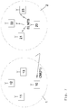
- FIG. 1 illustrates an arrangement comprising a first communication system 1 and a second communication system.
- the second communication system is a wireless token ring system 2 .
- each communication node 20 - 23 of the wireless token ring system directly or indirectly—i.e. via one or more other communication nodes that function as relay nodes—sends a token T to an allocated downstream communication node of the wireless token ring system and receives a token from an allocated upstream communication node of the wireless token ring system.
- an arrow visualizes the assignment of upstream and downstream nodes with respect to one another.
- the communication node 20 is configured to act as a handover control node in case that a communication node of another communication system intends to join the wireless token ring system 2 .
- the first communication system 1 may be based on any communication standard known in the art.
- the first communication system 1 may also be a wireless token ring system.
- each communication node 10 - 13 of the first communication system 1 sends a token to an allocated downstream communication node and receives a token from an allocated upstream communication node.
- the communication node 13 of the first communication system 1 intends to leave the first communication system 1 and join the wireless token ring system 2 .
- the communication node 13 will be referred to as the moving node 13 .
- the initiation of the handover process will be communicated to the handover control node 20 of the wireless token ring system 2 by a handover message HOM( 13 ).
- the handover message HOM( 13 ) indicates the moving node 13 (see FIG. 2 ).
- the handover message HOM( 13 ) can be sent by any of the communication nodes 10 - 13 of the first communication system 1 , for instance by the moving node 13 itself.
- the handover message HOM( 13 ) is preferably sent by the handover control node.
- FIG. 1 it is assumed that the communication node 10 is a handover control node of the communication system 1 and therefore sends the handover message HOM( 13 ) to the handover control node 20 of the wireless token ring system 2 (see FIG. 2 ).
- the handover control node 20 of the wireless token ring system 2 After receiving the handover message HOM( 13 ) the handover control node 20 of the wireless token ring system 2 addresses its next token T( 21 ) to the moving node 13 and not to its formerly allocated downstream communication node 21 in the original wireless token ring system 2 (see FIG. 3 ).
- This next token T( 21 ) contains the information that the communication node 21 is the downstream node allocated to the moving node 13 in the enlarged wireless token ring system 2 .
- the moving node 13 receives the token T( 21 ) and sends thereafter an acknowledgement signal A to the handover control node and an own token T to its allocated downstream node 21 in the enlarged second token ring system 2 , the handover process is deemed to be completed and the moving node 13 forms the newly allocated downstream node of the handover control node 10 in the enlarged wireless token ring system 2 (see FIG. 4 ).
- the handover control node 20 In case that the handover control node 20 does not receive the acknowledgement signal A in a given period of time, the handover control node 20 assumes that the moving node 13 has not received the token T( 21 ) and therefore has not sent an own token T to the allocated downstream node 21 of the moving node 13 (see FIG. 5 ). In order to allow the token ring communication in the wireless token ring system 2 to proceed, the handover control node 20 sends a replacement token RT to the allocated downstream node 21 of the moving node 13 . The replacement token RT replaces the presumably missing token T of the moving node 13 and allows the other communication nodes 21 - 23 of the wireless token ring system 2 to uphold the token-based communication.
- the handover control node 20 repeats the above described steps of sending the token T( 21 ) to the moving node 13 and awaiting the acknowledgement signal A until the handover control node 20 receives the acknowledgement signal A from the moving node 13 or until the handover process is deemed to have failed and is aborted.
- the handover process is deemed to have failed and is aborted after the handover control node 20 of the wireless token ring system 2 has sent a predefined number (e.g. 100) of replacement tokens RT without success.
- the handover control node 20 of the wireless token ring system 20 may send an enlargement information EI to the communication nodes 21 - 23 of the wireless token ring system 2 .
- the enlargement information EI indicates the imminent or already implemented enlargement of the wireless token ring system 2 .
- the enlargement information EI may be transmitted upon receipt of the handover message HOM( 13 ).
- the enlargement information EI may be forwarded by a token from communication node to communication node inside the wireless token ring system 2 (see FIG. 1 ). Alternatively or additionally, the enlargement information EI may be simultaneously sent via a broadcast signal from the handover control node 20 of the wireless token ring system 2 to all other communication nodes 21 - 23 of the wireless token ring system 2 . The enlargement information EI is preferably sent before the token T( 21 ) is transmitted to the moving node 13 .
- the handover control node 20 of the wireless token ring system 2 may set a new timing schedule NTS and send the new timing schedule NTS to the communication nodes 21 - 23 of the wireless token ring system 2 as well as to the moving node 13 .
- the new timing schedule preferably defines the timing demands that have to be met by the communication nodes 13 , 21 - 23 in the enlarged wireless token ring system 2 .
- the new timing schedule NTS may be forwarded by a token from communication node to communication node inside the enlarged wireless token ring system 2 .
- the new timing schedule NTS may be simultaneously sent via a broadcast signal from the handover control node 20 to the communication nodes 13 and 21 - 23 .
- the new timing schedule NTS may be defined by or may at least also define the token holding times of the communication nodes in the wireless token ring system 2 .
- FIG. 6 illustrates a modification of the handover process described above.
- the moving node 13 After receiving the token T( 21 ), the moving node 13 only sends an own token T to its allocated downstream node 21 in the enlarged second token ring system 2 , but no additional acknowledgement signal A. Since the token T is transmitted wirelessly, is can also be received by the handover control node 20 which accepts the receipt of the moving node's token T as the required acknowledgement. In other words, in the embodiment of FIG. 6 , the moving node's token T that is addressed to the communication node 21 , also forms the acknowledgement for the handover control node 20 .
- the handover control node 20 In case that the handover control node 20 does not receive the token T from the moving node 13 in a given period of time, the handover control node 20 assumes that the moving node 13 has not received the token T( 21 ) (see FIG. 3 ). In order to allow the token ring communication in the wireless token ring system 2 to proceed, the handover control node 20 sends a replacement token RT to the allocated downstream node 21 of the moving node 13 as shown in FIG. 5 .
- the handover control node 20 repeats the above described steps of sending a token T( 21 ) to the moving node 13 and awaiting the implicit acknowledgement that is conveyed by the moving node's 13 token T, until the handover control node 20 receives this token T from the moving node 13 or until the handover process is deemed to have failed and is aborted.
- FIGS. 7-9 illustrate a further modification of the handover process described above with reference to FIG. 1-5 .
- the handover control node 20 of the wireless token ring system 2 After receiving the handover message HOM( 13 ) from the handover control node 10 of the communication system 1 , the handover control node 20 of the wireless token ring system 2 responds with a configuration message CM( 21 ) (see FIG. 7 ).
- the handover control node 10 of the communication system 1 forwards the configuration message CM( 21 ) to the moving node 13 (see FIG. 8 ).
- the configuration message C( 21 ) indicates to the moving node 13 that the communication node 21 of the wireless token ring system 2 will be its allocated downstream node in the enlarged wireless token ring system 2 .
- the token T′ (see FIG. 9 ) that is sent by the handover control node 20 of the wireless token ring system 2 to the moving node 13 , does not have to comprise any indication as to the allocation of nodes in the enlarged wireless token ring system 2 .
- FIG. 10 illustrates an exemplary embodiment of a communication node 100 that can form any of the communication nodes 10 - 13 and 20 - 21 in the communication systems 1 and 2 of FIGS. 1-9 .
- the communication node 100 comprises a transceiver 110 capable of transmitting and receiving electromagnetic radiation, a processor unit 120 and a memory 130 .
- the memory 130 stores a control program CP that allows the processor unit 120 to operate as explained above.
- the control program CP comprises a handover control software module HCS which—after activation—programs the processor such that the communication node may act as a handover control node 20 as described above.
- the handover control node 100 may address its next token to a moving node 13 and not to its formerly allocated downstream communication node 21 after receiving a handover message HOM that indicates the initiation of the handover process with respect to the moving node 13 .
- the handover control node 100 may send a replacement token RT to the allocated downstream node 21 of the moving node 13 in case that the handover control node 20 does not receive an acknowledgement (e. g. an acknowledgment signal A or a token T) from the moving node 13 in a given period of time.
- an acknowledgement e. g. an acknowledgment signal A or a token T
- the embodiments described above with reference to FIGS. 1 to 10 differ from the method described in the above mentioned thesis “WTRP—Wireless Token Ring Protocol” at least with regard to the handover message.
- the handover message according to the exemplary embodiments of FIGS. 1 to 10 is sent from the first communication system to the second communication system in order to notify the second communication system about the intended handover process and announce the moving node.
- the handover message enables the handover control node of the second communication system to allow the announced moving node to move seamlessly and interruption-free from the first communication system to the second communication system.
- the handover control node of the second communication system awaits the arrival of the moving node and seamlessly executes the integration of the moving node upon arrival.
- This seamless integration which is the basis for session continuity on higher communication layers—referred to as “handover” with respect to FIGS. 1 to 10 —is possible because of the prior transmission of handover information (handover message) from the first communication system towards to the second communication system.
- the “solicit successor token” of the thesis is sent within the second system, only.
- the “solicit successor token” is meant for any node that can hear it, and therefore allows any arbitrary node to join the network.
- the “solicit successor token” potentially enables any node to enter the network and is not limited to a pre-defined moving node that has been and announced earlier by the first communication system.
Landscapes
- Engineering & Computer Science (AREA)
- Computer Networks & Wireless Communication (AREA)
- Signal Processing (AREA)
- Mobile Radio Communication Systems (AREA)
- Small-Scale Networks (AREA)
Abstract
Description
Claims (17)
Applications Claiming Priority (4)
| Application Number | Priority Date | Filing Date | Title |
|---|---|---|---|
| EP17170773 | 2017-05-12 | ||
| EP17170773.0A EP3402293A1 (en) | 2017-05-12 | 2017-05-12 | Wireless token ring system mobility |
| EP17170773.0 | 2017-05-12 | ||
| PCT/EP2018/061392 WO2018206402A1 (en) | 2017-05-12 | 2018-05-03 | Handover process |
Publications (2)
| Publication Number | Publication Date |
|---|---|
| US20210120474A1 US20210120474A1 (en) | 2021-04-22 |
| US11026150B2 true US11026150B2 (en) | 2021-06-01 |
Family
ID=58709288
Family Applications (1)
| Application Number | Title | Priority Date | Filing Date |
|---|---|---|---|
| US16/606,688 Active 2038-06-25 US11026150B2 (en) | 2017-05-12 | 2018-05-03 | Handover process |
Country Status (5)
| Country | Link |
|---|---|
| US (1) | US11026150B2 (en) |
| EP (2) | EP3402293A1 (en) |
| JP (1) | JP7177972B2 (en) |
| CN (1) | CN110547032A (en) |
| WO (1) | WO2018206402A1 (en) |
Families Citing this family (1)
| Publication number | Priority date | Publication date | Assignee | Title |
|---|---|---|---|---|
| CN113824796B (en) * | 2021-10-22 | 2023-06-30 | 杭州宏杉科技股份有限公司 | Token passing method and device |
Citations (6)
| Publication number | Priority date | Publication date | Assignee | Title |
|---|---|---|---|---|
| US5490139A (en) * | 1994-09-28 | 1996-02-06 | International Business Machines Corporation | Mobility enabling access point architecture for wireless attachment to source routing networks |
| US6775255B1 (en) * | 1999-09-16 | 2004-08-10 | At&T Corp. | H.323 mobility architecture for terminal, user and service mobility |
| JP2004312665A (en) | 2003-03-24 | 2004-11-04 | Alpha Systems:Kk | Access control method in radio transmission line, radio transmission apparatus, radio transmission system and access control program in radio transmission line |
| US6859448B1 (en) * | 1999-09-16 | 2005-02-22 | At&T Corp. | H.323 mobility protocol for terminal, user and service mobility |
| US20090055909A1 (en) * | 2007-08-20 | 2009-02-26 | National Taiwan University Of Science And Technology | Data transmitting method with multiple token mechanism in wireless token ring protocol |
| DE102012206529A1 (en) | 2012-04-20 | 2013-10-24 | Rwth Aachen | Method for operating broadcast-type wireless real-time transmission system, involves giving logical subsequent to one node if data transmission is possible with preset probability, and finding relay node if transmission is not possible |
Family Cites Families (7)
| Publication number | Priority date | Publication date | Assignee | Title |
|---|---|---|---|---|
| JPH088573B2 (en) * | 1989-04-03 | 1996-01-29 | 株式会社東芝 | Data communication method of control system |
| EP0594197B1 (en) * | 1992-10-23 | 1999-05-06 | Cabletron Systems, Inc. | Improved negotiation protocol for establishment of full duplex communication on a token ring network |
| KR100212468B1 (en) * | 1996-12-09 | 1999-08-02 | 정선종 | Group communication device and control method using the same |
| JP4314342B2 (en) * | 2001-05-01 | 2009-08-12 | アイピージー エレクトロニクス 503 リミテッド | Wireless communication system |
| CN101820374B (en) * | 2006-06-26 | 2016-05-04 | 三菱电机株式会社 | The method for issuing token of communication node and annular communication system, token-ring communication method |
| KR101024472B1 (en) * | 2006-06-26 | 2011-03-23 | 미쓰비시덴키 가부시키가이샤 | Token Issuing Method and Token Ring Communication Method in Communication Node and Ring-shaped Communication System |
| CN102647323B (en) * | 2012-03-28 | 2015-01-07 | 华为技术有限公司 | Flow control method and device as well as clustering system |
-
2017
- 2017-05-12 EP EP17170773.0A patent/EP3402293A1/en not_active Withdrawn
-
2018
- 2018-05-03 WO PCT/EP2018/061392 patent/WO2018206402A1/en not_active Ceased
- 2018-05-03 CN CN201880026813.4A patent/CN110547032A/en active Pending
- 2018-05-03 EP EP18726342.1A patent/EP3622770B1/en active Active
- 2018-05-03 US US16/606,688 patent/US11026150B2/en active Active
- 2018-05-03 JP JP2019560678A patent/JP7177972B2/en active Active
Patent Citations (6)
| Publication number | Priority date | Publication date | Assignee | Title |
|---|---|---|---|---|
| US5490139A (en) * | 1994-09-28 | 1996-02-06 | International Business Machines Corporation | Mobility enabling access point architecture for wireless attachment to source routing networks |
| US6775255B1 (en) * | 1999-09-16 | 2004-08-10 | At&T Corp. | H.323 mobility architecture for terminal, user and service mobility |
| US6859448B1 (en) * | 1999-09-16 | 2005-02-22 | At&T Corp. | H.323 mobility protocol for terminal, user and service mobility |
| JP2004312665A (en) | 2003-03-24 | 2004-11-04 | Alpha Systems:Kk | Access control method in radio transmission line, radio transmission apparatus, radio transmission system and access control program in radio transmission line |
| US20090055909A1 (en) * | 2007-08-20 | 2009-02-26 | National Taiwan University Of Science And Technology | Data transmitting method with multiple token mechanism in wireless token ring protocol |
| DE102012206529A1 (en) | 2012-04-20 | 2013-10-24 | Rwth Aachen | Method for operating broadcast-type wireless real-time transmission system, involves giving logical subsequent to one node if data transmission is possible with preset probability, and finding relay node if transmission is not possible |
Non-Patent Citations (4)
| Title |
|---|
| European Search Report dated Oct. 26, 2017 issued in related EP Application No. 17170773.0; filed May 12, 2017. |
| International Search Report dated Jul. 17, 2018 issued in related PCT/EP2018/061392; filed May 3, 2018. |
| Mustafa Ergen; "WTRP-Wireless Token Ring Protocol"; B.S. Middle East Technical University; A thesis submitted in partial satisfaction of the Master of Science in the Electric Engineering and Computer Science in the Graduate Division of the University of California, Berkeley; Jan. 1, 2002; 127 pages. |
| Yuanguo Bi et al; "A Multi-Channel Token Ring Protocol for QoS Provisioning in Inter-Vehicle Communications"; IEEE Transactions of Wireless Communications; vol. 8; No. 11; Nov. 2009; pp. 5261-5631. |
Also Published As
| Publication number | Publication date |
|---|---|
| EP3622770C0 (en) | 2024-01-24 |
| EP3622770A1 (en) | 2020-03-18 |
| US20210120474A1 (en) | 2021-04-22 |
| CN110547032A (en) | 2019-12-06 |
| JP2020522910A (en) | 2020-07-30 |
| WO2018206402A1 (en) | 2018-11-15 |
| EP3402293A1 (en) | 2018-11-14 |
| EP3622770B1 (en) | 2024-01-24 |
| JP7177972B2 (en) | 2022-11-25 |
Similar Documents
| Publication | Publication Date | Title |
|---|---|---|
| US9414105B2 (en) | Mobile source device media playback over rendering devices at lifestyle-determined locations | |
| EP2992727B1 (en) | Multicast group reuse in cellular network multicast transport | |
| TW201010469A (en) | Mac protocol for multi-channel wireless networks | |
| EP3132647A1 (en) | Method and apparatus for reducing the length of a packet storm in a wireless mesh network | |
| CN107925584B (en) | Proximity service user equipment - Proximity service priority control for multicast traffic in network relay scenarios | |
| KR101739680B1 (en) | Enhancements to resource allocation for mbsfn transmission in an mbsfn area | |
| CN101207439B (en) | Communication means between at least one subscriber board and at least two base station | |
| CN114047689B (en) | Lighting equipment control method and device, lighting equipment and storage medium | |
| WO2020064840A1 (en) | Mobile device and method | |
| US20250374313A1 (en) | Systems, devices, and methods related to configuring multi-stream network with stream-aware scheduling | |
| CN106341483A (en) | Local area network multicast group-based distributed dispatching system communication method | |
| US11026150B2 (en) | Handover process | |
| US10284605B2 (en) | Method and terminal for providing MCPTT service | |
| CN110463135B (en) | Full duplex transmission method and device | |
| US10405149B2 (en) | Enhanced MBMS-based signal transmission/reception method | |
| CN105144629A (en) | Multi-cast optimized medium access method for wireless network | |
| CN105429767A (en) | Group-establishing method and group-establishing system of audio groups, and equipment | |
| CN104285424A (en) | Method for transmitting data in a packet-oriented communication network and correspondingly arranged user equipment on the communication network | |
| US9287925B2 (en) | Systems and methods for frequency hopping in wireless communication systems | |
| WO2011064911A1 (en) | Terminal device and communication method | |
| US11540053B2 (en) | Method of synchronizing pieces of audio equipment | |
| CN108463972B (en) | MBMS Bearer Handling | |
| CN112154618B (en) | Communication systems, control systems and communication devices | |
| EP3373524B1 (en) | Audio stream network with network components and method for running and/or configuring the network with network components | |
| JP2020522910A5 (en) |
Legal Events
| Date | Code | Title | Description |
|---|---|---|---|
| AS | Assignment |
Owner name: R3 - RELIABLE REALTIME RADIO COMMUNICATIONS GMBH, GERMANY Free format text: ASSIGNMENT OF ASSIGNORS INTEREST;ASSIGNORS:BOHGE, MATHIAS;BONANATI, FLORIAN;GROSS, JAMES;REEL/FRAME:050764/0962 Effective date: 20190927 |
|
| FEPP | Fee payment procedure |
Free format text: ENTITY STATUS SET TO UNDISCOUNTED (ORIGINAL EVENT CODE: BIG.); ENTITY STATUS OF PATENT OWNER: SMALL ENTITY |
|
| FEPP | Fee payment procedure |
Free format text: ENTITY STATUS SET TO SMALL (ORIGINAL EVENT CODE: SMAL); ENTITY STATUS OF PATENT OWNER: SMALL ENTITY |
|
| STPP | Information on status: patent application and granting procedure in general |
Free format text: PUBLICATIONS -- ISSUE FEE PAYMENT RECEIVED |
|
| STPP | Information on status: patent application and granting procedure in general |
Free format text: PUBLICATIONS -- ISSUE FEE PAYMENT VERIFIED |
|
| STCF | Information on status: patent grant |
Free format text: PATENTED CASE |
|
| AS | Assignment |
Owner name: R3 SOLUTIONS GMBH, GERMANY Free format text: ASSIGNMENT OF ASSIGNORS INTEREST;ASSIGNOR:RELIABLE REALTIME RADIO COMMUNICATIONS GMBH;REEL/FRAME:061127/0385 Effective date: 20220822 |
|
| AS | Assignment |
Owner name: R3 SOLUTIONS GMBH, GERMANY Free format text: ASSIGNMENT OF ASSIGNORS INTEREST;ASSIGNOR:R3 - RELIABLE REALTIME RADIO COMMUNICATIONS GMBH;REEL/FRAME:061128/0030 Effective date: 20220822 |
|
| MAFP | Maintenance fee payment |
Free format text: PAYMENT OF MAINTENANCE FEE, 4TH YR, SMALL ENTITY (ORIGINAL EVENT CODE: M2551); ENTITY STATUS OF PATENT OWNER: SMALL ENTITY Year of fee payment: 4 |