US11026019B2 - Ambisonic signal noise reduction for microphone arrays - Google Patents
Ambisonic signal noise reduction for microphone arrays Download PDFInfo
- Publication number
- US11026019B2 US11026019B2 US16/352,272 US201916352272A US11026019B2 US 11026019 B2 US11026019 B2 US 11026019B2 US 201916352272 A US201916352272 A US 201916352272A US 11026019 B2 US11026019 B2 US 11026019B2
- Authority
- US
- United States
- Prior art keywords
- ambisonic
- noise
- order
- gain factor
- signal
- Prior art date
- Legal status (The legal status is an assumption and is not a legal conclusion. Google has not performed a legal analysis and makes no representation as to the accuracy of the status listed.)
- Active, expires
Links
Images


Classifications
-
- G—PHYSICS
- G10—MUSICAL INSTRUMENTS; ACOUSTICS
- G10L—SPEECH ANALYSIS TECHNIQUES OR SPEECH SYNTHESIS; SPEECH RECOGNITION; SPEECH OR VOICE PROCESSING TECHNIQUES; SPEECH OR AUDIO CODING OR DECODING
- G10L21/00—Speech or voice signal processing techniques to produce another audible or non-audible signal, e.g. visual or tactile, in order to modify its quality or its intelligibility
- G10L21/02—Speech enhancement, e.g. noise reduction or echo cancellation
- G10L21/0208—Noise filtering
-
- H—ELECTRICITY
- H04—ELECTRIC COMMUNICATION TECHNIQUE
- H04R—LOUDSPEAKERS, MICROPHONES, GRAMOPHONE PICK-UPS OR LIKE ACOUSTIC ELECTROMECHANICAL TRANSDUCERS; ELECTRIC HEARING AIDS; PUBLIC ADDRESS SYSTEMS
- H04R1/00—Details of transducers, loudspeakers or microphones
- H04R1/20—Arrangements for obtaining desired frequency or directional characteristics
- H04R1/32—Arrangements for obtaining desired frequency or directional characteristics for obtaining desired directional characteristic only
- H04R1/40—Arrangements for obtaining desired frequency or directional characteristics for obtaining desired directional characteristic only by combining a number of identical transducers
- H04R1/406—Arrangements for obtaining desired frequency or directional characteristics for obtaining desired directional characteristic only by combining a number of identical transducers microphones
-
- H—ELECTRICITY
- H04—ELECTRIC COMMUNICATION TECHNIQUE
- H04R—LOUDSPEAKERS, MICROPHONES, GRAMOPHONE PICK-UPS OR LIKE ACOUSTIC ELECTROMECHANICAL TRANSDUCERS; ELECTRIC HEARING AIDS; PUBLIC ADDRESS SYSTEMS
- H04R3/00—Circuits for transducers
- H04R3/005—Circuits for transducers for combining the signals of two or more microphones
-
- H—ELECTRICITY
- H04—ELECTRIC COMMUNICATION TECHNIQUE
- H04S—STEREOPHONIC SYSTEMS
- H04S3/00—Systems employing more than two channels, e.g. quadraphonic
- H04S3/02—Systems employing more than two channels, e.g. quadraphonic of the matrix type, i.e. in which input signals are combined algebraically, e.g. after having been phase shifted with respect to each other
-
- H—ELECTRICITY
- H04—ELECTRIC COMMUNICATION TECHNIQUE
- H04S—STEREOPHONIC SYSTEMS
- H04S7/00—Indicating arrangements; Control arrangements, e.g. balance control
- H04S7/30—Control circuits for electronic adaptation of the sound field
-
- H—ELECTRICITY
- H04—ELECTRIC COMMUNICATION TECHNIQUE
- H04R—LOUDSPEAKERS, MICROPHONES, GRAMOPHONE PICK-UPS OR LIKE ACOUSTIC ELECTROMECHANICAL TRANSDUCERS; ELECTRIC HEARING AIDS; PUBLIC ADDRESS SYSTEMS
- H04R2499/00—Aspects covered by H04R or H04S not otherwise provided for in their subgroups
- H04R2499/10—General applications
- H04R2499/11—Transducers incorporated or for use in hand-held devices, e.g. mobile phones, PDA's, camera's
-
- H—ELECTRICITY
- H04—ELECTRIC COMMUNICATION TECHNIQUE
- H04R—LOUDSPEAKERS, MICROPHONES, GRAMOPHONE PICK-UPS OR LIKE ACOUSTIC ELECTROMECHANICAL TRANSDUCERS; ELECTRIC HEARING AIDS; PUBLIC ADDRESS SYSTEMS
- H04R2499/00—Aspects covered by H04R or H04S not otherwise provided for in their subgroups
- H04R2499/10—General applications
- H04R2499/15—Transducers incorporated in visual displaying devices, e.g. televisions, computer displays, laptops
-
- H—ELECTRICITY
- H04—ELECTRIC COMMUNICATION TECHNIQUE
- H04S—STEREOPHONIC SYSTEMS
- H04S2400/00—Details of stereophonic systems covered by H04S but not provided for in its groups
- H04S2400/15—Aspects of sound capture and related signal processing for recording or reproduction
-
- H—ELECTRICITY
- H04—ELECTRIC COMMUNICATION TECHNIQUE
- H04S—STEREOPHONIC SYSTEMS
- H04S2420/00—Techniques used stereophonic systems covered by H04S but not provided for in its groups
- H04S2420/11—Application of ambisonics in stereophonic audio systems
Definitions
- the present disclosure is generally related to microphones.
- wireless telephones such as mobile and smart phones, tablets and laptop computers that are small, lightweight, and easily carried by users.
- These devices can communicate voice and data packets over wireless networks.
- many such devices incorporate additional functionality such as a digital still camera, a digital video camera, a digital recorder, and an audio file player.
- such devices can process executable instructions, including software applications, such as a web browser application, that can be used to access the Internet. As such, these devices can include significant computing capabilities.
- a higher-order ambisonics (HOA) signal (often represented by a plurality of spherical harmonic coefficients (SHC) or other hierarchical elements) is a three-dimensional representation of a soundfield.
- the HOA signal, or SHC representation of the HOA signal may represent the soundfield in a manner that is independent of local speaker geometry used to playback a multi-channel audio signal rendered from the HOA signal.
- the HOA signal may also facilitate backwards compatibility as the HOA signal may be rendered to multi-channel formats, such as a 5.1 audio channel format or a 7.1 audio channel format.
- Microphones used to capture audio for direct ambisonic conversion introduce “hiss” noise that may be audible during playback.
- Applying noise reduction, such as Wiener filtering and spectral subtraction, at the microphones can impair audio quality and introduce errors in direction information of audio signals.
- Applying Wiener filtering and spectral subtraction independently at loudspeakers during playback also introduces audio quality artefacts when loudspeaker contributions are added at the listener's position.
- a device is configured to apply noise reduction to ambisonic signals.
- the device includes a memory configured to store noise data corresponding to microphones in a microphone array.
- the device also includes a processor configured to perform signal processing operations on signals captured by microphones in the microphone array to generate multiple sets of ambisonic signals.
- the multiple sets of ambisonic signals include a first set corresponding to a first particular ambisonic order and a second set corresponding to a second particular ambisonic order.
- the processor is also configured to perform a first noise reduction operation that includes applying a first gain factor to each ambisonic signal in the first set.
- the first gain factor is based on the noise data.
- the processor is also configured to perform a second noise reduction operation that includes applying a second gain factor to each ambisonic signal in the second set.
- the second gain factor is based on the noise data and is distinct from the first gain factor.
- a method of reducing noise in ambisonic signals includes performing signal processing operations on signals captured by microphones in a microphone array to generate ambisonic signals.
- the ambisonic signals include multiple sets of ambisonic signals including a first set corresponding to a first particular ambisonic order and a second set corresponding to a second particular ambisonic order.
- the method includes performing a first noise reduction operation that includes applying a first gain factor to each ambisonic signal in the first set.
- the first gain factor is based on noise data corresponding to the microphones.
- the method includes performing a second noise reduction operation that includes applying a second gain factor to each ambisonic signal in the second set.
- the second gain factor is based on the noise data and is distinct from the first gain factor.
- a non-transitory computer-readable medium includes instructions that, when executed by a processor, cause the processor to perform operations to cause the processor to perform operations to apply noise reduction to ambisonic signals.
- the operations include performing signal processing operations on signals captured by microphones in a microphone array to generate ambisonic signals.
- the ambisonic signals include multiple sets of ambisonic signals including a first set corresponding to a first particular ambisonic order and a second set corresponding to a second particular ambisonic order.
- the operations include performing a first noise reduction operation that includes applying a first gain factor to each ambisonic signal in the first set.
- the first gain factor is based on noise data corresponding to the microphones.
- the operations also include performing a second noise reduction operation that includes applying a second gain factor to each ambisonic signal in the second set.
- the second gain factor is based on the noise data and is distinct from the first gain factor.
- an apparatus to apply noise reduction to ambisonic signals includes means for storing noise data corresponding to microphones in a microphone array.
- the apparatus includes means for performing signal processing operations on signals captured by microphones in the microphone array to generate multiple sets of ambisonic signals.
- the multiple sets of ambisonic signals include a first set corresponding to a first particular ambisonic order and a second set corresponding to a second particular ambisonic order.
- the apparatus includes means for performing a first noise reduction operation that includes applying a first gain factor to each ambisonic signal in the first set.
- the first gain factor is based on the noise data.
- the apparatus also includes means for performing a second noise reduction operation that includes applying a second gain factor to each ambisonic signal in the second set.
- the second gain factor is based on the noise data and is distinct from the first gain factor.
- FIG. 1A is a diagram illustrating spherical harmonic basis functions of various orders and sub-orders.
- FIG. 1B is a block diagram illustrating a first implementation of components of an ambisonic noise reduction system.
- FIG. 2 is a block diagram illustrating a second implementation of components of an ambisonic noise reduction system.
- FIG. 3 is a block diagram illustrating a third implementation of components of an ambisonic noise reduction system.
- FIG. 4A is a block diagram illustrating a fourth implementation of components of an ambisonic noise reduction system.
- FIG. 4B is a block diagram illustrating a fifth implementation of components of an ambisonic noise reduction system.
- FIG. 4C is a block diagram illustrating a sixth implementation of components of an ambisonic noise reduction system.
- FIG. 4D is a block diagram illustrating a seventh implementation of components of an ambisonic noise reduction system.
- FIG. 4E is a block diagram illustrating an eighth implementation of components of an ambisonic noise reduction system.
- FIG. 5 illustrates an illustrative implementation of a mobile device that includes components of the microphone array of FIG. 1B .
- FIG. 6A illustrates an illustrative implementation of an optical wearable that includes components of the microphone array in FIG. 1B .
- FIG. 6B illustrates an illustrative implementation of a computer that includes components of the microphone array in FIG. 1B .
- FIG. 6C illustrates an illustrative implementation of a camera that includes components of the microphone array in FIG. 1B .
- FIG. 6D illustrates an illustrative implementation of an augmented reality headset that includes components of the microphone array in FIG. 1B .
- FIG. 7 illustrates an example of a method for noise reduction of ambisonic signals.
- FIG. 8 is a block diagram of a particular illustrative example of a mobile device that is operable to perform the techniques described with reference to FIGS. 1A-7 .
- Conventional techniques for reducing noise introduced by microphone arrays that capture audio for direct ambisonic conversion can generate undesirable effects. For example, applying conventional noise reduction at the microphones can impair audio quality and introduce errors in direction information of audio signals, while applying conventional noise reduction independently at loudspeakers during playback also introduces audio quality artefacts when loudspeaker contributions are added at the listener's position.
- the present disclosure describes noise reduction devices and techniques that reduce or eliminate the impaired audio quality and errors in direction information associated with conventional techniques.
- improved noise reduction can be performed that includes, for each ambisonic order, determining microphone noise for the microphones contributing to signals of that ambisonic order, and using the microphone noise to generate a gain factor that is applied to the signals of that ambisonic order.
- an ordinal term e.g., “first,” “second,” “third,” etc.
- an element such as a structure, a component, an operation, etc.
- the term “set” refers to one or more of a particular element
- the term “plurality” refers to multiple (e.g., two or more) of a particular element.
- Coupled may include communicatively coupled, electrically coupled, magnetically coupled, physically coupled, optically coupled, and combinations thereof.
- Two devices (or components) may be coupled (e.g., communicatively coupled, electrically coupled, or physically coupled) directly or indirectly via one or more other devices, components, wires, buses, networks (e.g., a wired network, a wireless network, or a combination thereof), etc.
- Two devices (or components) that are electrically coupled may be included in the same device or in different devices and may be connected via electronics, one or more connectors, or inductive coupling, as illustrative, non-limiting examples.
- two devices (or components) that are communicatively coupled, such as in electrical communication may send and receive electrical signals (digital signals or analog signals) directly or indirectly, such as via one or more wires, buses, networks, etc.
- determining may be used to describe how one or more operations are performed. It should be noted that such terms are not to be construed as limiting and other techniques may be utilized to perform similar operations. Additionally, as referred to herein, “generating”, “calculating”, “estimating”, “using”, “selecting”, “accessing”, and “determining” may be used interchangeably. For example, “generating”, “calculating”, “estimating”, or “determining” a parameter (or a signal) may refer to actively generating, estimating, calculating, or determining the parameter (or the signal) or may refer to using, selecting, or accessing the parameter (or signal) that is already generated, such as by another component or device.
- Higher-order ambisonics audio data may include at least one higher-order ambisonic (HOA) coefficient corresponding to a spherical harmonic basis function having an order greater than one.
- HOA higher-order ambisonic
- the evolution of surround sound has made available many audio output formats for entertainment. Examples of such consumer surround sound formats are mostly ‘channel’ based in that they implicitly specify feeds to loudspeakers in certain geometrical coordinates.
- the consumer surround sound formats include the popular 5.1 format (which includes the following six channels: front left (FL), front right (FR), center or front center, back left or surround left, back right or surround right, and low frequency effects (LFE)), the growing 7.1 format, and various formats that includes height speakers such as the 7.1.4 format and the 22.2 format (e.g., for use with the Ultra High Definition Television standard).
- Non-consumer formats can span any number of speakers (in symmetric and non-symmetric geometries) often termed ‘surround arrays’.
- One example of such a sound array includes 32 loudspeakers positioned at coordinates on the corners of a truncated icosahedron.
- the input to a future Moving Picture Experts Group (MPEG) encoder is optionally one of three possible formats: (i) traditional channel-based audio (as discussed above), which is meant to be played through loudspeakers at pre-specified positions; (ii) object-based audio, which involves discrete pulse-code-modulation (PCM) data for single audio objects with associated metadata containing their location coordinates (amongst other information); or (iii) scene-based audio, which involves representing the soundfield using coefficients of spherical harmonic basis functions (also called “spherical harmonic coefficients” or SHC, “Higher-order Ambisonics” or HOA, and “HOA coefficients”).
- SHC spherical harmonic coefficients
- HOA Higher-order Ambisonics
- the future MPEG encoder may be described in more detail in a document entitled “Call for Proposals for 3D Audio,” by the International Organization for Standardization/International Electrotechnical Commission (ISO)/(IEC) JTC1/SC29/WG11/N13411, released January 2013 in Geneva, Switzerland, and available at http://mpeg.chiariglione.org/sites/default/files/files/standards/parts/docs/w13411.zip.
- ISO International Organization for Standardization/International Electrotechnical Commission
- IEC International Electrotechnical Commission
- a hierarchical set of elements may be used to represent a soundfield.
- the hierarchical set of elements may refer to a set of elements in which the elements are ordered such that a basic set of lower-ordered elements provides a full representation of the modeled soundfield. As the set is extended to include higher-order elements, the representation becomes more detailed, increasing resolution.
- SHC spherical harmonic coefficients
- k ⁇ c , c is the speed of sound ( ⁇ 343 m/s), ⁇ r r , ⁇ r , ⁇ r ⁇ is a point of reference (or observation point), j n ( ⁇ ) is the spherical Bessel function of order n, and Y n m ( ⁇ r , ⁇ r ) are the spherical harmonic basis functions of order n and suborder m.
- the term in square brackets is a frequency-domain representation of the signal (i.e., S ( ⁇ , r r , ⁇ r , ⁇ r )) which can be approximated by various time-frequency transformations, such as the discrete Fourier transform (DFT), the discrete cosine transform (DCT), or a wavelet transform.
- DFT discrete Fourier transform
- DCT discrete cosine transform
- wavelet transform a frequency-domain representation of the signal
- hierarchical sets include sets of wavelet transform coefficients and other sets of coefficients of multiresolution basis functions.
- the SHC A n m (k) can either be physically acquired (e.g., recorded) by various microphone array configurations or, alternatively, they can be derived from channel-based or object-based descriptions of the soundfield.
- the SHC represent scene-based audio, where the SHC may be input to an audio encoder to obtain encoded SHC that may promote more efficient transmission or storage. For example, a fourth-order representation involving (1+4) 2 (25, and hence fourth order) coefficients may be used.
- the SHC may be derived from a microphone recording using a microphone array.
- Various examples of how SHC may be derived from microphone arrays are described in Poletti, M., “Three-Dimensional Surround Sound Systems Based on Spherical Harmonics,” J. Audio Eng. Soc., Vol. 53, No. 11, 2005 November, pp. 1004-1025.
- a n m (k) g ( ⁇ )( ⁇ 4 ⁇ ik ) h n (2) ( kr s ) Y n m *( ⁇ s , ⁇ s ), where i is ⁇ square root over ( ⁇ 1 ) ⁇ , h n (2) ( ⁇ ) is the spherical Hankel function (of the second kind) of order n, and ⁇ r s , ⁇ s , ⁇ s ⁇ is the location of the object.
- Knowing the object source energy g( ⁇ ) as a function of frequency enables conversion of each PCM object and the corresponding location into the SHC A n m (k). Further, it can be shown (since the above is a linear and orthogonal decomposition) that the A n m (k) coefficients for each object are additive. In this manner, a multitude of PCM objects can be represented by the A n m (k) coefficients (e.g., as a sum of the coefficient vectors for the individual objects).
- the coefficients contain information about the soundfield (the pressure as a function of 3D coordinates), and the above represents the transformation from individual objects to a representation of the overall soundfield, in the vicinity of the observation point ⁇ r r , ⁇ r , ⁇ r ⁇ .
- a system 100 for generating ambisonic signals using a microphone array and performing noise reduction to the ambisonic signals is shown.
- the system 100 may be integrated into multiple devices.
- the system 100 may be integrated into a robot, a mobile phone, a head-mounted display, a virtual reality headset, or an optical wearable (e.g., glasses).
- the system 100 includes a microphone array 102 configured to provide audio data 104 to a processor 101 that includes an ambisonics conversion circuit 110 .
- Ambisonic signals 112 corresponding to the audio data 104 are output by the ambisonics conversion circuit 110 and provided to a noise reduction block 120 in the processor 101 .
- Noise reduced ambisonics signals 130 are output by the noise reduction block 120 and correspond to noise-reduced versions of the ambisonic signals 112 .
- the microphone array 102 includes multiple microphones configured to capture the audio data 104 .
- the microphone array 102 may have a spherical microphone array configuration, such as an Eigenmike or Zylia spherical array.
- the microphone array 102 has another configuration, such as a linear array configuration, a tetrahedral configuration, or any other regular or non-regular configuration.
- the microphone array 102 may include any number of microphones, such as four microphones, eight microphones, or 32 microphones, as illustrative, non-limiting examples.
- the ambisonic signals 112 include a first set 114 corresponding to a zero-order ambisonic signal (e.g., a W signal), a second set 115 corresponding to first order ambisonic signals (e.g., X, Y, and Z signals), a third set 116 corresponding to second order ambisonic signals, and one or more additional sets including a set 117 corresponding to N-th order ambisonic signals (where N is an integer greater than 2).
- a zero-order ambisonic signal e.g., a W signal
- first order ambisonic signals e.g., X, Y, and Z signals
- third set 116 corresponding to second order ambisonic signals
- additional sets including a set 117 corresponding to N-th order ambisonic signals (where N is an integer greater than 2).
- the noise reduced ambisonics signals 130 include a first set 134 corresponding to a noise-reduced version of the first set 114 (e.g., a W signal), a second set 135 corresponding to a noise-reduced version of the second set 115 , a third set 136 corresponding to a noise-reduced version of the third set 116 , and one or more additional sets including a set 137 corresponding to a noise-reduced version of the set 117 .
- a first set 134 corresponding to a noise-reduced version of the first set 114 (e.g., a W signal)
- a second set 135 corresponding to a noise-reduced version of the second set 115
- a third set 136 corresponding to a noise-reduced version of the third set 116
- one or more additional sets including a set 137 corresponding to a noise-reduced version of the set 117 .
- the noise reduction block 120 includes a frequency-domain vector-type noise subtraction circuit 124 configured to process the first set 114 to generate the noise-reduced first set 134 , a frequency-domain vector-type noise subtraction circuit 125 configured to process the second set 115 to generate the noise-reduced second set 135 , a frequency-domain vector-type noise subtraction circuit 126 configured to process the third set 116 to generate the noise-reduced third set 136 , and one or more frequency-domain vector-type noise subtraction circuits including a frequency-domain vector-type noise subtraction circuit 127 configured to process the set 117 to generate the noise-reduced set 137 .
- the noise reduction block 120 is configured to process each order of the ambisonic signals 112 independently of the other orders of the ambisonic signals 112 .
- Noise data 142 is stored in a memory 140 that is coupled to the processor 101 .
- the noise data 142 includes noise measurement data, corresponding to each of the ambisonic orders, that is used to perform vector-type noise subtraction to reduce noise in the ambisonic signals.
- Higher orders of the ambisonic signals 112 generally have higher noise than lower orders of the ambisonic signals 112 , and thus may be subjected to greater noise suppression in the noise reduction block 120 .
- directional information in each order of the ambisonic signals 112 is independent of the directional information in the other orders of the ambisonics signals 112 , with higher orders having higher resolution directional information as compared to lower orders.
- the frequency-domain vector-type noise subtraction circuit 124 performs noise reduction on ambisonic signals of order 0
- the frequency-domain vector-type noise subtraction circuit 125 performs noise reduction on ambisonic signals of order 1
- the frequency-domain vector-type noise subtraction circuit 126 performs noise reduction on ambisonic signals of order 2
- another frequency-domain vector-type noise subtraction circuit (not shown) performs noise reduction on ambisonic signals of order 3
- the frequency-domain vector-type noise subtraction circuit 127 performs noise reduction on ambisonic signals of order 4.
- each of the five active frequency-domain vector-type noise subtraction circuits operates independently of, and in parallel with, each other to generate the noise-reduced ambisonics signals 130 .
- the noise reduction block 120 includes nine active frequency-domain vector-type noise subtraction circuits, and each of the nine active frequency-domain vector-type noise subtraction circuits operates independently of, and in parallel with, each other to generate the noise-reduced ambisonics signals 130 .
- N may be any integer greater than 1.
- each of the frequency-domain vector-type noise subtraction circuits 124 - 127 of the noise reduction block 120 is configured to determine a gain value particular to the respective set 114 - 117 of ambisonic signals and to apply the gain value uniformly across the signals within the respective set 114 - 117 .
- Applying gain values for each order of the ambisonic signals 112 independently of the other orders enables greater noise suppression at higher orders as compared to lesser noise suppression at lower orders, and applying gain values uniformly across the signals for each order preserves directional information for each order (or reduces distortion of the directional information) as compared to conventional noise reduction techniques.
- FIG. 2 illustrates an example implementation 200 of components of the system 100 of FIG. 1 that are used to determine a noise power of a particular order of the ambisonic signals 112 during a period of silence to determine frequency-dependent noise of the microphone array 102 of FIG. 1 at each ambisonic order.
- Noise power of that particular order of the ambisonic signals 112 at the particular frequency is represented as a noise vector 232 having a length indicative of total noise power at that frequency and having the same (or substantially the same) direction as the signal vector 230 .
- Subtraction of the noise vector 232 from the signal vector 230 results in a noise-reduced signal vector 234 that has reduced power (vector length) as compared to the signal vector 230 while preserving the direction of the signal vector 230 .
- the implementation 200 includes multiple power computation circuits 210 - 214 .
- Each power computation circuit 210 - 214 is configured to generate a channel noise power value based on a square average of the received samples 202 for that channel.
- Channel noise power values from each of the power computation circuits 210 - 214 are summed at an adder 220 .
- a square root circuit 222 is configured to perform a square root operation to the output of the adder 220 to generate a noise power value 224 for the particular ambisonic order.
- a noise-only higher-order ambisonic (HOA) signal for the microphone array 102 of FIG. 1 can be generated in anechoic conditions (e.g., during factory or manufacturer testing of the microphone array 102 ) or quiet conditions (e.g., in response to an electronic device (e.g., a smart phone) detecting little to no ambient sound, such as during late-night or early-morning hours, prompting the electronic device to perform a calibration operation to update noise-only signal data from the microphone array 102 ).
- an electronic device e.g., a smart phone
- ⁇ 2 nm (f) represents a noise power of the m-th sub-order of the n-th order ambisonic signal (e.g., an output from one of the power computation circuits 210 - 214 ).
- the values of N n (f) for all values of n and f may be stored as noise data for use during noise reduction operations, as described further with reference to FIGS. 3-4 .
- FIG. 3 illustrates an example implementation of components 300 of the system 100 of FIG. 1 that are used to generate noise-reduced ambisonic signals of a particular order of the ambisonic signals 112 .
- the components 300 may be implemented in each of the frequency-domain vector-type noise subtraction circuits 124 - 127 of FIG. 1 .
- the components 300 includes multiple power computation circuits 310 - 314 .
- Each power computation circuit 310 - 314 is configured to generate a channel noise power value based on a square average of the received samples for that channel 302 .
- Channel noise power values from each of the power computation circuits 310 - 314 are summed at an adder 320 .
- a square root circuit 322 is configured to perform a square root operation to the output of the adder 320 to generate a total power value (total_order_power) 324 for the particular ambisonic order.
- the power computation circuits 310 - 314 , the adder 320 , and the square root circuit 322 correspond to the power computation circuits 210 - 214 , the adder 220 , and the square root circuit 222 , respectively, of FIG. 2 .
- ⁇ 2 nm (f) represents a signal power of the m-th channel of the n-th order ambisonic signal (e.g., an output from one of the power computation circuits 310 - 314 ).
- a gain computation circuit 334 is configured to receive the noise power value (noise_power) 224 (e.g., N n (f)) and the total power value (total_order_power) 324 (e.g., P n (f)) and to compute a gain factor 336 based on the noise power and the total power.
- the gain computation circuit 334 is configured to apply a smoothing parameter to a previous gain factor.
- the previous gain factor is based on previous frequency samples of each ambisonic signal in the set of ambisonic signals for a particular ambisonic order and at the particular frequency, such as:
- g n t ⁇ ( f ) ⁇ ⁇ ⁇ g n t - 1 ⁇ ( f ) + ( 1 - ⁇ ) ⁇ P n ⁇ ( f ) - ⁇ ⁇ ( f ) ⁇ N n ⁇ ( f ) P n ⁇ ( f )
- g n t (f) represents the gain factor 336 at frequency f for a set of samples corresponding to a time frame t and for ambisonic order n
- ⁇ represents an aggressiveness and can vary with frequency—how much of noise power to subtract—and has a value between 0-1
- ⁇ represents a smoothing parameter that affects how quickly the gain changes over time
- g n t-1 (f) represents the previous gain factor at frequency f for a set of samples corresponding to a time frame t ⁇ 1 that precedes time frame t and for ambisonic order n.
- a scaling circuit 330 is configured to scale the samples of each of the ambisonic signals 302 of the order based on the gain factor 336 .
- each of the signals 302 may be multiplied by the gain factor 336 to generate noise-subtracted signals 332 .
- scaling the samples of each ambisonic signal 302 in each of the sets 114 , 115 , 116 , and 117 , based on the particular gain factor 336 that is computed for that set 114 , 115 , 116 , or 117 reduces noise without distorting directional information corresponding to that set 114 , 115 , 116 , or 117 .
- a device to apply noise reduction to ambisonic signals includes the memory 140 configured to store noise data 142 corresponding to microphones in the microphone array 102 .
- the device also includes the processor 101 .
- the processor 101 is configured to perform, via the ambisonics conversion circuit 110 , signal processing operations on signals (e.g., the audio data 104 ) captured by microphones in the microphone array 102 to generate multiple sets 114 - 117 of ambisonic signals 112 .
- the multiple sets 114 - 117 of the ambisonic signals 112 include a first set (e.g., set 115 ) corresponding to a first particular ambisonic order (e.g., first order) and a second set (e.g., set 116 ) corresponding to a second particular ambisonic order (e.g., second order).
- the first set of ambisonic signals is the set 115
- the second set of ambisonic signals is the set 116 .
- the processor 101 is configured to perform a first noise reduction operation that includes applying a first gain factor to each ambisonic signal in the first set (set 115 ).
- the first gain factor is based on the noise data 142 .
- the processor 101 is also configured to perform a second noise reduction operation that includes applying a second gain factor to each ambisonic signal in the second set (set 116 ).
- the processor 101 is configured to receive, via a user interface, one or more user inputs corresponding to parameters of at least one of the first noise reduction operation or the second noise reduction operation.
- the processor 101 may be incorporated in a device that includes a display screen and may be configured to generate the user interface for display at the display screen, such as described in further detail with reference to FIG. 5 .
- the system 400 includes the processor 101 and the microphone array 102 of FIG. 1 .
- the system 100 , the system 400 , or any combination thereof may be integrated into a robot, a mobile phone, a head-mounted display, a virtual reality headset, or an optical wearable (e.g., glasses).
- the microphone array 102 includes a microphone 412 , a microphone 414 , a microphone 416 , and a microphone 418 .
- at least one microphone 412 , 414 , 416 , 418 is an omnidirectional microphone.
- at least one microphone 412 , 414 , 416 , 418 is configured to capture sound with approximately equal gain for all sides and directions.
- at least one of the microphones 412 , 414 , 416 , 418 is a microelectromechanical system (MEMS) microphone.
- MEMS microelectromechanical system
- the microphones 412 , 414 , 416 , 418 are positioned in a tetrahedral configuration. However, it should be understood that the microphones 412 , 414 , 416 , 418 may be arranged in different configurations (e.g., a spherical configuration, such as an Eigenmike or Zylia spherical array, a triangular configuration, a random configuration, etc.).
- the microphone array 102 is shown to include four microphones, in other implementations, the microphone array 102 may include fewer than four microphones or more than four microphones. For example, the microphone array 102 may include three microphones, eight microphones, or any other number of microphones.
- the system 400 also includes signal processing circuitry that is coupled to the microphone array 102 .
- the signal processing circuitry includes a signal processor 420 , a signal processor 422 , a signal processor 424 , and a signal processor 426 .
- the signal processing circuitry is configured to perform signal processing operations on analog signals captured by each microphone 412 , 414 , 416 , 418 to generate digital signals.
- the microphone 412 is configured to capture an analog signal 413
- the microphone 414 is configured to capture an analog signal 415
- the microphone 416 is configured to capture an analog signal 417
- the microphone 418 is configured to capture an analog signal 419 .
- the signal processor 420 is configured to perform first signal processing operations (e.g., filtering operations, gain adjustment operations, analog-to-digital conversion operations) on the analog signal 413 to generate a digital signal 433 .
- first signal processing operations e.g., filtering operations, gain adjustment operations, analog-to-digital conversion operations
- the signal processor 422 is configured to perform second signal processing operations on the analog signal 415 to generate a digital signal 435
- the signal processor 424 is configured to perform third signal processing operations on the analog signal 417 to generate a digital signal 437
- the signal processor 426 is configured to perform fourth signal processing operations on the analog signal 419 to generate a digital signal 439 .
- Each signal processor 420 , 422 , 424 , 426 includes an analog-to-digital converter (ADC) 421 , 423 , 425 , 427 , respectively, to perform the analog-to-digital conversion operations.
- ADC analog-to-digital converter
- the ADCs 421 , 423 , 425 , 427 are integrated into a coder/decoder (CODEC). According to another implementation, the ADCs 421 , 423 , 425 , 427 are stand-alone ADCs. According to yet another implementation, the ADCs 421 , 423 , 425 , 427 are included in the microphone array 102 . Thus, in some scenarios, the microphone array 102 may generate the digital signals 433 , 435 , 437 , 439 .
- Each digital signal 433 , 435 , 437 , 439 is provided to one or more directivity adjusters 450 of the processor 101 .
- two directivity adjusters 452 , 454 are shown. However, it should be understood that any number of directivity adjusters may be included in the system 400 .
- the number of active directivity adjusters 450 may be selected based on information generated at a microphone analyzer 440 of the processor 101 , as described below.
- the microphone analyzer 440 is coupled to the microphone array 102 via a control bus 446 , and the microphone analyzer 440 is coupled to the directivity adjusters 450 and the filters 470 via a control bus 447 .
- the microphone analyzer 440 is configured to determine position information 441 for each microphone of the microphone array 102 , orientation information 442 for each microphone of the microphone array 102 , and power level information 443 for each microphone of the microphone array 102 .
- the processor 101 Based on the position information 441 , the orientation information 442 , and the power level information 443 , the processor 101 selects a number of directivity adjusters 450 to activate, sets of multiplicative factors 453 and 455 to be used at the active directivity adjusters 450 , one or more sets of the filters 471 - 478 to activate, and filter coefficients 459 for each of the activated filters 471 - 478 .
- the microphone analyzer 440 enables the processor 101 to compensate for flexible positioning of the microphone (e.g., a “non-ideal” tetrahedral microphone arrangement) by adjusting the number of active directivity adjusters 450 , filters 470 , multiplicative factors 453 , 455 , and filter coefficients 457 , 459 based on the position of the microphones, the orientation of the microphones, etc.
- the directivity adjusters 450 and the filters 470 apply different transfer functions to the digital signals 433 , 435 , 437 , 439 based on the placement and directivity of the microphones 412 , 414 , 416 , 418 .
- the microphone analyzer 440 also includes a noise measurement circuit 408 configured to generate the noise data 142 .
- the noise measurement circuit 408 may include the components illustrated in FIG. 2 and may be activated by the processor 101 during a period of silence to generate the noise data 142 .
- the directivity adjuster 452 may be configured to apply the first set of multiplicative factors 453 to the digital signals 433 , 435 , 437 , 439 to generate a first set of ambisonic signals 461 - 464 .
- the directivity adjuster 452 may apply the first set of multiplicative factors 453 to the digital signals 433 , 435 , 437 , 439 using a first matrix multiplication.
- the first set of ambisonic signals includes a W signal 461 , an X signal 462 , a Y signal 463 , and a Z signal 464 .
- the directivity adjuster 454 may be configured to apply the second set of multiplicative factors 455 to the digital signals 433 , 435 , 437 , 439 to generate a second set of ambisonic signals 465 - 168 .
- the directivity adjuster 454 may apply the second set of multiplicative factors 455 to the digital signals 433 , 435 , 437 , 439 using a second matrix multiplication.
- the second set of ambisonic signals includes a W signal 465 , an X signal 466 , a Y signal 467 , and a Z signal 468 .
- the first set of filters 471 - 474 are configured to filter the first set of ambisonic signals 461 - 164 to generate a filtered first set of ambisonic signals 481 - 484 .
- the second set of filters 475 - 478 are configured to filter the second set of ambisonic signals 465 - 468 to generate a filtered second set of ambisonic signals 485 - 488 .
- the system 400 also includes combination circuitry 495 - 498 coupled to the first set of filters 471 - 474 and to the second set of filters 475 - 478 .
- the combination circuitry 495 - 498 is configured to combine the filtered first set of ambisonic signals 481 - 484 and the filtered second set of ambisonic signals 485 - 488 to generate a processed set of ambisonic signals 491 - 494 .
- the ambisonic signals and the noise data 142 are provided to the noise reduction block 120 to generate the noise reduced ambisonics signals 130 , such as described with reference to FIG. 1 and FIG. 3 .
- FIG. 4B illustrates another example implementation of a system 401 that includes components of the system 400 of FIG. 4A but omits components directed to adjustability and flexibility of antenna placement and orientation, such as the microphone analyzer 440 , the filters 475 - 478 , the combination circuitry 495 - 498 , and the directivity adjusters 450 .
- the digital signals 433 - 439 are processed at a matrix multiplier 402 that is configured to perform multiplication operations using a set of multiplicative factors 403 to generate the ambisonic signals 461 - 464 .
- the matrix multiplier 402 corresponds to the ambisonics conversion circuit 110 of FIG. 1B .
- the noise data 142 is depicted in the memory 140 and accessible to the noise reduction block 120 . However, in other embodiments, all or part of the noise data 142 is stored within the processor 101 , such as in a nonvolatile storage (e.g., flash cells, read-only memory (ROM)) or a volatile storage (e.g., registers) accessible to, or included within, the noise reduction block 120 .
- a nonvolatile storage e.g., flash cells, read-only memory (ROM)
- a volatile storage e.g., registers
- the system 401 has reduced cost, power consumption, and complexity.
- the system 401 is configured to generate ambisonic signals based on a single arrangement of the microphones 412 , 414 , 416 , and 418 , such as when the microphones 412 , 414 , 416 , and 418 are at fixed locations.
- the system 401 may be implemented in portable electronic devices having a fixed antenna arrangement. Examples of various portable electronic devices are illustrated in FIGS. 5 and 6A-6D
- the system 400 and the system 401 provide illustrative, non-limiting examples of systems that include the noise reduction block 120 of FIG. 1 and that are configured to perform noise reduction for ambisonic signals. Because the systems 400 and 401 convert the captured sounds to ambisonics, the captured sounds may be played back over a plurality of loudspeaker configurations and the captured sounds may be rotated to adapt to a consumer head position.
- FIGS. 4A and 4B in addition to FIGS. 4C and 4D , below
- the techniques are not limited to first order ambisonics and may also be performed using higher order ambisonics.
- FIG. 4C illustrates another example implementation of a system 404 that omits components that are peripheral to noise reduced ambisonic signal generation, such as the microphone array 102 , the signal processors 420 , 422 , 424 , and 426 , and the memory 140 .
- the processor 101 is configured to receive the audio data 104 from a microphone array, such as ‘M’ microphones on a device or structure, such as microphones on a three-dimensional (3D) camera or on a rigid sphere (e.g., an Eigenmike).
- the processor 101 includes combinations of mixing matrices and filters 405 .
- the combinations 405 may include circuitry configured to combine mixing matrix multiplication operations and filtering operations to generate the ambisonic signals 112 (e.g.
- the combinations 405 combine matrix multiplications operations of the matrix multiplier 402 and filtering operations of the filters 471 - 474 into a combined processing operation, rather than the serial operations (e.g., multiplication followed by filtering) illustrated in FIGS. 4A-4B .
- FIG. 4D illustrates another example implementation of a system 406 to generate noise reduced ambisonic signals.
- a device 407 e.g., a chip or integrated circuit
- the noise reduction block 120 inputs (e.g., pins or pads) configured to receive ambisonic signals 112 (e.g., from a remote ambisonic antenna array and signal conversion processor) and outputs (e.g., pins or pads) configured to output the noise reduced ambisonics signals 130 (e.g., to a remote playback loudspeaker system).
- noise data 142 may be received via one or more inputs and stored at the device 407 for use at the noise reduction block 120 .
- FIG. 4E illustrates an example implementation of a system in which the processor 101 is within the microphone array 102 .
- the microphone array 102 has a substantially spherical housing with regularly spaced microphones.
- the processor 101 is within the housing and coupled to receive and process audio data from the microphones.
- the noise-reduced ambisonics signals 130 generated by the processor 101 are provided as output signals of the microphone array 102 .
- the microphone array 102 may function as an “intelligent array” that outputs noise reduced ambisonic signals, enabling ambisonic sound with a reduced number of components, increased simplicity of system setup, and enhanced component interoperability, as compared to systems in which a microphone array and an ambisonic processor are separate components that are manually configured to operate with each other.
- the microphone array 102 has other configurations.
- FIGS. 4A-4E illustrate non-limiting examples of various architectures in which the present techniques can be applied to generate noise-reduced ambisonic signals.
- a mobile device e.g. a mobile phone
- the microphone 412 is located on a front side of the mobile device.
- the microphone 412 is located near a screen 510 of the mobile device.
- the microphone 418 is located on a back side of the mobile device.
- the microphone 418 is located near a camera 512 of the mobile device.
- the microphones 414 , 416 are located on top of the mobile device.
- a user interface 520 may be displayed on the screen 510 , such as a touch screen, to enable a user to provide user input corresponding to a noise reduction operation.
- the user interface 520 enables the user to select or adjust values of the aggressiveness parameter ⁇ , the smoothing parameter ⁇ , or a combination thereof, that are described with reference to FIG. 3 , overall or individually for each order.
- the user input indicates a single value of the parameter for multiple ambisonic orders, and in other implementations the user input indicates individual values of the parameter for multiple ambisonic orders.
- the user input indicates a playback system.
- the user interface 520 enables the user to indicate a loudspeaker configuration that is to be used for playback. Based on the loudspeaker configuration, one or more aspects of noise reduction may be adjusted. For example, if the user input indicates a loudspeaker configuration that uses a relatively low number of channels, such as 5.1, binaural or 7.1.4, a parameter for noise reduction is selected based on the playback system. For binaural a less aggressive noise reduction may be used since playback is over two channels. As more channels are added, more aggressive noise reduction can be applied. Thus, the user interface 520 enables user selection of aggressiveness of noise reduction.
- aggressiveness of noise reduction (e.g., a value of the aggressiveness parameter ⁇ ) is automatically adjusted based on playback history instead of via direct user input via the user interface 520 . For example, if a history of playback is primarily binaural then noise reduction can be automatically set to be less aggressive as compared to a history of playback primarily on 5.1 systems.
- the user interface 520 is omitted, while in other such implementations the user interface 520 is included and enables a user to override an automatically-selected aggressiveness setting.
- power savings may be obtained using a field of view (FOV) or region-based system based on a camera, such as the optical wearable described with reference to FIG. 6A or the augmented reality headset described with reference to FIG. 6D .
- FOV field of view
- noise reduction is bypassed for a particular ambisonic order if the vector direction for the particular ambisonic order is not within the FOV.
- noise reduction is performed at reduced gain depending on the normalized direction between the center of FOV and the order vector.
- an optical wearable 600 that includes the components of the microphone array 102 of FIGS. 4A-4B is shown.
- the microphones 412 , 414 , 416 are located on a right side of the optical wearable 600
- the microphone 418 is located on a top-left corner of the optical wearable 600 .
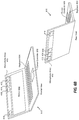
- a computer 610 (e.g., a laptop) that includes the components of the microphone array 102 of FIGS. 4A-4B is shown.
- the computer 610 includes a screen 602 , a keyboard 604 , and a cursor controller 606 .
- a frontal view of the computer 610 is shown and a rear view of the computer 610 is shown.
- the microphone array 102 is located above the screen 602 .
- the microphone array 102 may be positioned at other locations of the computer 610 .
- the microphone array 102 may be positioned along a bottom portion (e.g., by the cursor controller 606 ) of the computer 610 or may be positioned along a side portion of the computer 610 .
- FIG. 6C a camera 620 that includes the components of the microphone array 102 of FIGS. 4A-4B is shown.
- FIG. 6D an augmented reality headset 640 that includes the components of the microphone array 102 of FIGS. 4A-4B is shown.
- a method 700 for noise reduction in ambisonic signals is shown.
- the method 700 (or portions of the method 700 ) may be performed by the system 100 of FIG. 1B , the system 400 of FIG. 4A , the system 401 of FIG. 4B , the system 404 of FIG. 4C , the system 406 of FIG. 4D , or a combination thereof.
- the method 700 may be performed by the processor 101 of FIG. 1
- the method 700 includes performing signal processing operations on signals captured by microphones in a microphone array to generate ambisonic signals, at 702 .
- the ambisonic signals include multiple sets of ambisonic signals including a first set corresponding to a first particular ambisonic order and a second set corresponding to a second particular ambisonic order.
- the method 700 includes, at 704 , performing a first noise reduction operation that includes applying a first gain factor to each ambisonic signal in the first set.
- the first gain factor is based on noise data corresponding to the microphones.
- the method 700 also includes, at 706 , performing a second noise reduction operation that includes applying a second gain factor to each ambisonic signal in the second set.
- the second gain factor is based on the noise data and distinct from the first gain factor.
- Performing noise reduction by applying separate gain values to different orders of ambisonic signal reduces distortion of direction information and reduces sound quality artefacts as compared to performing noise reduction at the microphones, at the loudspeakers, or both.
- FIG. 8 a block diagram of a particular illustrative implementation of a device (e.g., a wireless communication device) is depicted and generally designated 800 .
- the device 800 may have more components or fewer components than illustrated in FIG. 8 .
- the device 800 includes a processor 806 , such as a central processing unit (CPU) or a digital signal processor (DSP), coupled to a memory 853 .
- the memory 853 includes instructions 860 (e.g., executable instructions) such as computer-readable instructions or processor-readable instructions.
- the instructions 860 may include one or more instructions that are executable by a computer, such as the processor 806 or a processor 810 , such to perform operations in accordance with the method 700 of FIG. 7 .
- FIG. 8 also illustrates a display controller 826 that is coupled to the processor 810 and to a display 828 .
- a coder/decoder (CODEC) 834 may also be coupled to the processor 806 .
- a speaker 836 and the microphones 412 , 414 , 416 , 418 may be coupled to the CODEC 834 .
- the CODEC 834 includes the noise reduction block 120 and other components of the system 100 .
- the processors 806 , 810 may include the noise reduction block 120 , other components of the system 100 , or a combination thereof.
- a transceiver 811 may be coupled to the processor 810 and to an antenna 842 , such that wireless data received via the antenna 842 and the transceiver 811 may be provided to the processor 810 .
- the processor 810 , the display controller 826 , the memory 853 , the CODEC 834 , and the transceiver 811 are included in a system-in-package or system-on-chip device 822 .
- an input device 830 and a power supply 844 are coupled to the system-on-chip device 822 .
- each of the display 828 , the input device 830 , the speaker 836 , the microphones 412 , 414 , 416 , 418 , the antenna 842 , and the power supply 844 are external to the system-on-chip device 822 .
- each of the display 828 , the input device 830 , the speaker 836 , the microphones 412 , 414 , 416 , 418 , the antenna 842 , and the power supply 844 may be coupled to a component of the system-on-chip device 822 , such as an interface or a controller.
- the device 800 may include a headset, a mobile communication device, a smart phone, a cellular phone, a laptop computer, a computer, a tablet, a personal digital assistant, a display device, a television, a gaming console, a music player, a radio, a digital video player, a digital video disc (DVD) player, a tuner, a camera, a navigation device, a vehicle, a component of a vehicle, or any combination thereof, as illustrative, non-limiting examples.
- a headset a mobile communication device
- a smart phone a cellular phone
- a laptop computer a computer
- a computer a tablet
- a personal digital assistant a display device
- a television a gaming console, a music player, a radio, a digital video player, a digital video disc (DVD) player, a tuner, a camera, a navigation device, a vehicle, a component of a vehicle, or any combination thereof, as illustrative, non-limiting
- the memory 853 may include or correspond to a non-transitory computer readable medium storing the instructions 860 .
- the instructions 860 may include one or more instructions that are executable by a computer, such as the processors 810 , 806 or the CODEC 834 .
- the instructions 860 may cause the processor 810 to perform one or more operations described herein, including but not limited to one or more portions of the method 700 of FIG. 7 .
- one or more components of the systems and devices disclosed herein may be integrated into a decoding system or apparatus (e.g., an electronic device, a CODEC, or a processor therein), into an encoding system or apparatus, or both.
- a decoding system or apparatus e.g., an electronic device, a CODEC, or a processor therein
- one or more components of the systems and devices disclosed herein may be integrated into a wireless telephone, a tablet computer, a desktop computer, a laptop computer, a set top box, a music player, a video player, an entertainment unit, a television, a game console, a navigation device, a communication device, a personal digital assistant (PDA), a fixed location data unit, a personal media player, or another type of device.
- PDA personal digital assistant
- an apparatus includes means for storing noise data corresponding to microphones in a microphone array, such as the memory 140 .
- the apparatus also includes means for performing signal processing operations on signals captured by microphones in the microphone array to generate multiple sets of ambisonic signals, such as the ambisonics conversion circuit 110 .
- the multiple sets of ambisonic signals include a first set corresponding to a first particular ambisonic order and a second set corresponding to a second particular ambisonic order.
- the apparatus also includes means for performing a first noise reduction operation that includes applying a first gain factor to each ambisonic signal in the first set, the first gain factor based on the noise data, such as the frequency-domain vector-type noise subtraction circuit 124 , 125 , 126 , or 127 , one or more of the components 300 of FIG. 3 , or a combination thereof.
- the apparatus further includes means for performing a second noise reduction operation that includes applying a second gain factor to each ambisonic signal in the second set, the second gain factor based on the noise data and distinct from the first gain factor, such as the frequency-domain vector-type noise subtraction circuit 124 , 125 , 126 , or 127 , one or more of the components 300 of FIG. 3 , or a combination thereof.
- One example audio ecosystem may include audio content, movie studios, music studios, gaming audio studios, channel based audio content, coding engines, game audio stems, game audio coding/rendering engines, and delivery systems.
- the movie studios, the music studios, and the gaming audio studios may receive audio content.
- the audio content may represent the output of an acquisition.
- the movie studios may output channel based audio content (e.g., in 2.0, 5.1, and 7.1) such as by using a digital audio workstation (DAW).
- the music studios may output channel based audio content (e.g., in 2.0, and 5.1) such as by using a DAW.
- the coding engines may receive and encode the channel based audio content based one or more codecs (e.g., AAC, AC3, Dolby True HD, Dolby Digital Plus, and DTS Master Audio) for output by the delivery systems.
- codecs e.g., AAC, AC3, Dolby True HD, Dolby Digital Plus, and DTS Master Audio
- the gaming audio studios may output one or more game audio stems, such as by using a DAW.
- the game audio coding/rendering engines may code and or render the audio stems into channel based audio content for output by the delivery systems.
- Another example context in which the techniques may be performed includes an audio ecosystem that may include broadcast recording audio objects, professional audio systems, consumer on-device capture, HOA audio format, on-device rendering, consumer audio, TV, and accessories, and car audio systems.
- the broadcast recording audio objects, the professional audio systems, and the consumer on-device capture may all code their output using HOA audio format.
- the audio content may be coded using the HOA audio format into a single representation that may be played back using the on-device rendering, the consumer audio, TV, and accessories, and the car audio systems.
- the single representation of the audio content may be played back at a generic audio playback system (i.e., as opposed to requiring a particular configuration such as 5.1, 7.1, etc.).
- the acquisition elements may include wired and/or wireless acquisition devices (e.g., Eigen microphones), on-device surround sound capture, and mobile devices (e.g., smartphones and tablets).
- wired and/or wireless acquisition devices may be coupled to mobile device via wired and/or wireless communication channel(s).
- the mobile device may be used to acquire a soundfield.
- the mobile device may acquire a soundfield via the wired and/or wireless acquisition devices and/or the on-device surround sound capture (e.g., a plurality of microphones integrated into the mobile device).
- the mobile device may then code the acquired soundfield into the HOA coefficients for playback by one or more of the playback elements.
- a user of the mobile device may record (acquire a soundfield of) a live event (e.g., a meeting, a conference, a play, a concert, etc.), and code the recording into HOA coefficients.
- a live event e.g., a meeting, a conference, a play, a concert, etc.
- the mobile device may also utilize one or more of the playback elements to playback the HOA coded soundfield. For instance, the mobile device may decode the HOA coded soundfield and output a signal to one or more of the playback elements that causes the one or more of the playback elements to recreate the soundfield.
- the mobile device may utilize the wireless and/or wireless communication channels to output the signal to one or more speakers (e.g., speaker arrays, sound bars, etc.).
- the mobile device may utilize docking solutions to output the signal to one or more docking stations and/or one or more docked speakers (e.g., sound systems in smart cars and/or homes).
- the mobile device may utilize headphone rendering to output the signal to a set of headphones, e.g., to create realistic binaural sound.
- a particular mobile device may both acquire a 3D soundfield and playback the same 3D soundfield at a later time.
- the mobile device may acquire a 3D soundfield, encode the 3D soundfield into HOA, and transmit the encoded 3D soundfield to one or more other devices (e.g., other mobile devices and/or other non-mobile devices) for playback.
- an audio ecosystem may include audio content, game studios, coded audio content, rendering engines, and delivery systems.
- the game studios may include one or more DAWs which may support editing of HOA signals.
- the one or more DAWs may include HOA plugins and/or tools which may be configured to operate with (e.g., work with) one or more game audio systems.
- the game studios may output new stem formats that support HOA.
- the game studios may output coded audio content to the rendering engines which may render a soundfield for playback by the delivery systems.
- the techniques may also be performed with respect to exemplary audio acquisition devices.
- the techniques may be performed with respect to an Eigen microphone which may include a plurality of microphones that are collectively configured to record a 3D soundfield.
- the plurality of microphones of Eigen microphone may be located on the surface of a substantially spherical ball with a radius of approximately 4 cm.
- Another exemplary audio acquisition context may include a production truck which may be configured to receive a signal from one or more microphones, such as one or more Eigen microphones.
- the production truck may also include an audio encoder.
- the mobile device may also, in some instances, include a plurality of microphones that are collectively configured to record a 3D soundfield.
- the plurality of microphone may have X, Y, Z diversity.
- the mobile device may include a microphone which may be rotated to provide X, Y, Z diversity with respect to one or more other microphones of the mobile device.
- the mobile device may also include an audio encoder.
- Example audio playback devices that may perform various aspects of the techniques described in this disclosure are further discussed below.
- speakers and/or sound bars may be arranged in any arbitrary configuration while still playing back a 3D soundfield.
- headphone playback devices may be coupled to a decoder via either a wired or a wireless connection.
- a single generic representation of a soundfield may be utilized to render the soundfield on any combination of the speakers, the sound bars, and the headphone playback devices.
- a number of different example audio playback environments may also be suitable for performing various aspects of the techniques described in this disclosure.
- a 5.1 speaker playback environment a 2.0 (e.g., stereo) speaker playback environment, a 9.1 speaker playback environment with full height front loudspeakers, a 22.2 speaker playback environment, a 16.0 speaker playback environment, an automotive speaker playback environment, and a mobile device with ear bud playback environment may be suitable environments for performing various aspects of the techniques described in this disclosure.
- a single generic representation of a soundfield may be utilized to render the soundfield on any of the foregoing playback environments.
- the techniques of this disclosure enable a rendered to render a soundfield from a generic representation for playback on the playback environments other than that described above. For instance, if design considerations prohibit proper placement of speakers according to a 7.1 speaker playback environment (e.g., if it is not possible to place a right surround speaker), the techniques of this disclosure enable a render to compensate with the other 6 speakers such that playback may be achieved on a 6.1 speaker playback environment.
- the 3D soundfield of the sports game may be acquired (e.g., one or more Eigen microphones may be placed in and/or around the baseball stadium), HOA coefficients corresponding to the 3D soundfield may be obtained and transmitted to a decoder, the decoder may reconstruct the 3D soundfield based on the HOA coefficients and output the reconstructed 3D soundfield to a renderer, the renderer may obtain an indication as to the type of playback environment (e.g., headphones), and render the reconstructed 3D soundfield into signals that cause the headphones to output a representation of the 3D soundfield of the sports game.
- the type of playback environment e.g., headphones
- a software module may reside in a memory device, such as random access memory (RAM), magnetoresistive random access memory (MRAM), spin-torque transfer MRAM (STT-MRAM), flash memory, read-only memory (ROM), programmable read-only memory (PROM), erasable programmable read-only memory (EPROM), electrically erasable programmable read-only memory (EEPROM), registers, hard disk, a removable disk, or a compact disc read-only memory (CD-ROM).
- RAM random access memory
- MRAM magnetoresistive random access memory
- STT-MRAM spin-torque transfer MRAM
- ROM read-only memory
- PROM programmable read-only memory
- EPROM erasable programmable read-only memory
- EEPROM electrically erasable programmable read-only memory
- registers hard disk, a removable disk, or a compact disc read-only memory (CD-ROM).
- An exemplary memory device is coupled to the processor such that the processor can read information from, and write information to, the memory device.
- the memory device may be integral to the processor.
- the processor and the storage medium may reside in an application-specific integrated circuit (ASIC).
- the ASIC may reside in a computing device or a user terminal.
- the processor and the storage medium may reside as discrete components in a computing device or a user terminal.
Landscapes
- Engineering & Computer Science (AREA)
- Physics & Mathematics (AREA)
- Acoustics & Sound (AREA)
- Health & Medical Sciences (AREA)
- Signal Processing (AREA)
- Otolaryngology (AREA)
- General Health & Medical Sciences (AREA)
- Mathematical Optimization (AREA)
- Theoretical Computer Science (AREA)
- Pure & Applied Mathematics (AREA)
- Mathematical Physics (AREA)
- Computational Linguistics (AREA)
- Quality & Reliability (AREA)
- Mathematical Analysis (AREA)
- Audiology, Speech & Language Pathology (AREA)
- Human Computer Interaction (AREA)
- Multimedia (AREA)
- General Physics & Mathematics (AREA)
- Algebra (AREA)
- Circuit For Audible Band Transducer (AREA)
Abstract
Description
The expression shows that the pressure pi at any point {rr, θr, φr} of the soundfield, at time t, can be represented uniquely by the SHC, An m(k). Here,
c is the speed of sound (˜343 m/s), {rr, θr, φr} is a point of reference (or observation point), jn(⋅) is the spherical Bessel function of order n, and Yn m (θr, φr) are the spherical harmonic basis functions of order n and suborder m. It can be recognized that the term in square brackets is a frequency-domain representation of the signal (i.e., S (ω, rr, θr, φr)) which can be approximated by various time-frequency transformations, such as the discrete Fourier transform (DFT), the discrete cosine transform (DCT), or a wavelet transform. Other examples of hierarchical sets include sets of wavelet transform coefficients and other sets of coefficients of multiresolution basis functions.
A n m(k)=g(ω)(−4πik)h n (2)(kr s)Y n m*(θs,φs),
where i is √{square root over (−1)}, hn (2)(⋅) is the spherical Hankel function (of the second kind) of order n, and {rs, θs, φs} is the location of the object. Knowing the object source energy g(ω) as a function of frequency (e.g., using time-frequency analysis techniques, such as performing a fast Fourier transform on the PCM stream) enables conversion of each PCM object and the corresponding location into the SHC An m(k). Further, it can be shown (since the above is a linear and orthogonal decomposition) that the An m(k) coefficients for each object are additive. In this manner, a multitude of PCM objects can be represented by the An m(k) coefficients (e.g., as a sum of the coefficient vectors for the individual objects). Essentially, the coefficients contain information about the soundfield (the pressure as a function of 3D coordinates), and the above represents the transformation from individual objects to a representation of the overall soundfield, in the vicinity of the observation point {rr, θr, φr}.
N n(f)=√{square root over (Σm=−n nβ2 nm(f))}
P n(f)=√{square root over (Σm=−n nα2 nm(f))}
Claims (26)
Priority Applications (1)
| Application Number | Priority Date | Filing Date | Title |
|---|---|---|---|
| US16/352,272 US11026019B2 (en) | 2018-09-27 | 2019-03-13 | Ambisonic signal noise reduction for microphone arrays |
Applications Claiming Priority (2)
| Application Number | Priority Date | Filing Date | Title |
|---|---|---|---|
| US201862737711P | 2018-09-27 | 2018-09-27 | |
| US16/352,272 US11026019B2 (en) | 2018-09-27 | 2019-03-13 | Ambisonic signal noise reduction for microphone arrays |
Publications (2)
| Publication Number | Publication Date |
|---|---|
| US20200107118A1 US20200107118A1 (en) | 2020-04-02 |
| US11026019B2 true US11026019B2 (en) | 2021-06-01 |
Family
ID=69946204
Family Applications (1)
| Application Number | Title | Priority Date | Filing Date |
|---|---|---|---|
| US16/352,272 Active 2039-11-29 US11026019B2 (en) | 2018-09-27 | 2019-03-13 | Ambisonic signal noise reduction for microphone arrays |
Country Status (1)
| Country | Link |
|---|---|
| US (1) | US11026019B2 (en) |
Families Citing this family (4)
| Publication number | Priority date | Publication date | Assignee | Title |
|---|---|---|---|---|
| CN111383650B (en) * | 2018-12-28 | 2024-05-03 | 深圳市优必选科技有限公司 | Robot and audio data processing method thereof |
| CN110459236B (en) * | 2019-08-15 | 2021-11-30 | 北京小米移动软件有限公司 | Noise estimation method, apparatus and storage medium for audio signal |
| US11564038B1 (en) * | 2021-02-11 | 2023-01-24 | Meta Platforms Technologies, Llc | Spherical harmonic decomposition of a sound field detected by an equatorial acoustic sensor array |
| US20240312468A1 (en) * | 2023-03-16 | 2024-09-19 | Apple Inc. | Spatial Audio Upscaling Using Machine Learning |
Citations (3)
| Publication number | Priority date | Publication date | Assignee | Title |
|---|---|---|---|---|
| US9865274B1 (en) * | 2016-12-22 | 2018-01-09 | Getgo, Inc. | Ambisonic audio signal processing for bidirectional real-time communication |
| US20190069083A1 (en) | 2017-08-24 | 2019-02-28 | Qualcomm Incorporated | Ambisonic signal generation for microphone arrays |
| US20200005760A1 (en) * | 2017-03-16 | 2020-01-02 | Panasonic Intellectual Property Management Co., Ltd. | Active noise reduction device and active noise reduction method |
-
2019
- 2019-03-13 US US16/352,272 patent/US11026019B2/en active Active
Patent Citations (3)
| Publication number | Priority date | Publication date | Assignee | Title |
|---|---|---|---|---|
| US9865274B1 (en) * | 2016-12-22 | 2018-01-09 | Getgo, Inc. | Ambisonic audio signal processing for bidirectional real-time communication |
| US20200005760A1 (en) * | 2017-03-16 | 2020-01-02 | Panasonic Intellectual Property Management Co., Ltd. | Active noise reduction device and active noise reduction method |
| US20190069083A1 (en) | 2017-08-24 | 2019-02-28 | Qualcomm Incorporated | Ambisonic signal generation for microphone arrays |
Also Published As
| Publication number | Publication date |
|---|---|
| US20200107118A1 (en) | 2020-04-02 |
Similar Documents
| Publication | Publication Date | Title |
|---|---|---|
| US10477310B2 (en) | Ambisonic signal generation for microphone arrays | |
| US9870778B2 (en) | Obtaining sparseness information for higher order ambisonic audio renderers | |
| CN106663433B (en) | Method and apparatus for processing audio data | |
| US9883310B2 (en) | Obtaining symmetry information for higher order ambisonic audio renderers | |
| EP3205122B1 (en) | Screen related adaptation of hoa content | |
| US10070094B2 (en) | Screen related adaptation of higher order ambisonic (HOA) content | |
| US20150264483A1 (en) | Low frequency rendering of higher-order ambisonic audio data | |
| US20160104493A1 (en) | Signaling layers for scalable coding of higher order ambisonic audio data | |
| US11026019B2 (en) | Ambisonic signal noise reduction for microphone arrays | |
| CN108141689B (en) | Transition from object-based audio to HOA | |
| US10455321B2 (en) | Microphone configurations | |
| US10134403B2 (en) | Crossfading between higher order ambisonic signals | |
| US9959876B2 (en) | Closed loop quantization of higher order ambisonic coefficients | |
| CN106104680A (en) | It is inserted into voice-grade channel in the description of sound field | |
| CN108780647B (en) | Method and apparatus for audio signal decoding | |
| US20190392846A1 (en) | Demixing data for backward compatible rendering of higher order ambisonic audio | |
| CN113994425A (en) | Quantizing spatial components based on bit allocation determined for psychoacoustic audio coding | |
| EP3149971B1 (en) | Obtaining sparseness information for higher order ambisonic audio renderers | |
| EP3149972B1 (en) | Obtaining symmetry information for higher order ambisonic audio renderers | |
| US20240259731A1 (en) | Artificial reverberation in spatial audio | |
| HK1233103B (en) | Screen related adaptation of hoa content |
Legal Events
| Date | Code | Title | Description |
|---|---|---|---|
| FEPP | Fee payment procedure |
Free format text: ENTITY STATUS SET TO UNDISCOUNTED (ORIGINAL EVENT CODE: BIG.); ENTITY STATUS OF PATENT OWNER: LARGE ENTITY |
|
| AS | Assignment |
Owner name: QUALCOMM INCORPORATED, CALIFORNIA Free format text: ASSIGNMENT OF ASSIGNORS INTEREST;ASSIGNORS:SALEHIN, S M AKRAMUS;SEN, DIPANJAN;SIGNING DATES FROM 20190426 TO 20190513;REEL/FRAME:049214/0469 |
|
| STPP | Information on status: patent application and granting procedure in general |
Free format text: NOTICE OF ALLOWANCE MAILED -- APPLICATION RECEIVED IN OFFICE OF PUBLICATIONS |
|
| STPP | Information on status: patent application and granting procedure in general |
Free format text: PUBLICATIONS -- ISSUE FEE PAYMENT RECEIVED |
|
| STPP | Information on status: patent application and granting procedure in general |
Free format text: PUBLICATIONS -- ISSUE FEE PAYMENT VERIFIED |
|
| STCF | Information on status: patent grant |
Free format text: PATENTED CASE |
|
| MAFP | Maintenance fee payment |
Free format text: PAYMENT OF MAINTENANCE FEE, 4TH YEAR, LARGE ENTITY (ORIGINAL EVENT CODE: M1551); ENTITY STATUS OF PATENT OWNER: LARGE ENTITY Year of fee payment: 4 |