US11025803B2 - Apparatus for capturing animal nose pattern images on mobile devices - Google Patents
Apparatus for capturing animal nose pattern images on mobile devices Download PDFInfo
- Publication number
- US11025803B2 US11025803B2 US16/649,267 US201716649267A US11025803B2 US 11025803 B2 US11025803 B2 US 11025803B2 US 201716649267 A US201716649267 A US 201716649267A US 11025803 B2 US11025803 B2 US 11025803B2
- Authority
- US
- United States
- Prior art keywords
- unit
- subunit
- illumination
- mobile device
- lens
- Prior art date
- Legal status (The legal status is an assumption and is not a legal conclusion. Google has not performed a legal analysis and makes no representation as to the accuracy of the status listed.)
- Active
Links
Images


Classifications
-
- H04N5/22521—
-
- A—HUMAN NECESSITIES
- A01—AGRICULTURE; FORESTRY; ANIMAL HUSBANDRY; HUNTING; TRAPPING; FISHING
- A01K—ANIMAL HUSBANDRY; AVICULTURE; APICULTURE; PISCICULTURE; FISHING; REARING OR BREEDING ANIMALS, NOT OTHERWISE PROVIDED FOR; NEW BREEDS OF ANIMALS
- A01K11/00—Marking of animals
- A01K11/006—Automatic identification systems for animals, e.g. electronic devices, transponders for animals
-
- G—PHYSICS
- G06—COMPUTING OR CALCULATING; COUNTING
- G06V—IMAGE OR VIDEO RECOGNITION OR UNDERSTANDING
- G06V10/00—Arrangements for image or video recognition or understanding
- G06V10/10—Image acquisition
- G06V10/12—Details of acquisition arrangements; Constructional details thereof
- G06V10/14—Optical characteristics of the device performing the acquisition or on the illumination arrangements
- G06V10/147—Details of sensors, e.g. sensor lenses
-
- G—PHYSICS
- G06—COMPUTING OR CALCULATING; COUNTING
- G06V—IMAGE OR VIDEO RECOGNITION OR UNDERSTANDING
- G06V10/00—Arrangements for image or video recognition or understanding
- G06V10/10—Image acquisition
- G06V10/17—Image acquisition using hand-held instruments
-
- G—PHYSICS
- G06—COMPUTING OR CALCULATING; COUNTING
- G06V—IMAGE OR VIDEO RECOGNITION OR UNDERSTANDING
- G06V40/00—Recognition of biometric, human-related or animal-related patterns in image or video data
- G06V40/10—Human or animal bodies, e.g. vehicle occupants or pedestrians; Body parts, e.g. hands
-
- H—ELECTRICITY
- H04—ELECTRIC COMMUNICATION TECHNIQUE
- H04N—PICTORIAL COMMUNICATION, e.g. TELEVISION
- H04N23/00—Cameras or camera modules comprising electronic image sensors; Control thereof
- H04N23/50—Constructional details
- H04N23/52—Elements optimising image sensor operation, e.g. for electromagnetic interference [EMI] protection or temperature control by heat transfer or cooling elements
-
- H—ELECTRICITY
- H04—ELECTRIC COMMUNICATION TECHNIQUE
- H04N—PICTORIAL COMMUNICATION, e.g. TELEVISION
- H04N23/00—Cameras or camera modules comprising electronic image sensors; Control thereof
- H04N23/50—Constructional details
- H04N23/55—Optical parts specially adapted for electronic image sensors; Mounting thereof
-
- H—ELECTRICITY
- H04—ELECTRIC COMMUNICATION TECHNIQUE
- H04N—PICTORIAL COMMUNICATION, e.g. TELEVISION
- H04N23/00—Cameras or camera modules comprising electronic image sensors; Control thereof
- H04N23/56—Cameras or camera modules comprising electronic image sensors; Control thereof provided with illuminating means
-
- H—ELECTRICITY
- H04—ELECTRIC COMMUNICATION TECHNIQUE
- H04N—PICTORIAL COMMUNICATION, e.g. TELEVISION
- H04N23/00—Cameras or camera modules comprising electronic image sensors; Control thereof
- H04N23/57—Mechanical or electrical details of cameras or camera modules specially adapted for being embedded in other devices
-
- H04N5/2254—
-
- H04N5/2256—
-
- H04N5/2257—
Definitions
- the present invention relates to an apparatus for capturing animal nose pattern images on mobile devices. Moreover, the present invention relates to the use of lens adapters and/or additional illumination in conjunction with the mobile device camera to acquire high quality nose pattern images.
- the nose pattern of certain animals is unique to each individual, just as the fingerprint pattern is unique to each individual human being.
- the first step is to acquire the animal nose pattern image, and for that there are two basically different approaches: contact type and non-contact type.
- the contact-type method obtains nose images either by the application of a pigment onto the nose for a contact impression print, or by using a capacitive touch sensor as used for fingerprints.
- the ink impression method has been used for a long time in places like Japan to identify cows, yet not only is it a rather cumbersome and delicate process that requires skill, but also impractical and inaccurate for an animal with a small nose.
- the contact method runs the risk of creating distorted impressions from applying too much or uneven pressure onto the nose.
- this invention introduces an auxiliary apparatus that can be attached to a mobile device to facilitate the acquisition of high quality nose pattern images.
- This apparatus is a simple one that forgoes the necessity of any modifications to the mobile device's hardware and also is universally compatible with all sorts of mobile device cameras.
- An auxiliary apparatus for mobile devices such as smart phones and tablets, for capturing animal nose pattern images is provided. It is attached to the exterior of the mobile device so as not to require any change to the mobile device itself. Its basic configuration is the combination of the mount unit and the shell unit. The mount unit, to which the shell unit is attached, grabs hold onto the frame of the mobile device. This mount unit, and hence the entire auxiliary apparatus, can be detached from the mobile device when it is not being used for the purpose of nose pattern image capture.
- the mount unit is designed to fit mobile devices of any size and the location of rear camera thereof.
- the shell unit whose length and opening size can be adjusted for the target animal, serves as a controlled image acquisition environment for capturing good quality nose pattern images by blocking out stray lights and providing an even lighting condition within. It also helps the user by providing a guide for the correct aiming of the camera and the correct focal (capture) distance.
- the camera used to capture the animal nose pattern image is the built-in one in the mobile device. Many, if not all, may not be adequate for this purpose, as animal noses are curved three-dimensional objects that can also often be very small. To remedy this situation, the present patent provides an additional lens attachment unit. With judicious selection and adjustment of the lens module the user can adjust the focal length, focal depth and the field of view to best fit the target animal. In particular with an additional macro lens, the user may take images with a sufficiently high resolution of small noses.
- the shell unit can be made translucent to evenly let through ambient light (i.e. light consistently present outside the shell), while blocking out stray lights (i.e. sudden flashes of light from camera flashes, passing cars, etc.) that cause stark reflections off the wet surface of the animal nose. If, however, the surrounding environment is not sufficiently bright, the luminosity through the translucent shell may not be enough to acquire clear, good quality nose pattern images.
- this invention provides an illumination unit.
- This illumination unit which comes in many shapes and forms, provides additional direct or indirect light sources.
- This invention also provides an aperture control mechanism to adjust depth of field, as well as to minimize light intake to avoid intense light reflections.
- Power may be provided for electronically controlled components, such as illumination, through different means: disposable battery, rechargeable battery, or power drawn from the mobile device itself.
- a control unit is also provided, to control pertinent user choices such as the luminosity and lighting pattern of the illumination unit, aperture opening, liquid lens convexity, and others.
- Animal nose pattern images acquired on a mobile device using the present invention may be used for matching against other images or templates to identify or verify the identity of the source individual animal unit.
- FIG. 1 shows a bad quality nose pattern image (a) and a good quality nose pattern image (b) and their respective close-up views;
- FIG. 2 illustrates an apparatus seen from different angles
- FIG. 3 illustrates an apparatus comprising a shell unit and a mount unit
- FIG. 4 illustrates a configuration of a mount unit, in which (a) and (b) further illustrate the flexibility of the mount unit;
- FIG. 5 illustrates different sizes of shells for an interchangeable-type shell unit
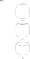
- FIG. 6 illustrates a shell unit in aperture-type form in tightened and loosened positions
- FIG. 7 illustrates assembled views of an apparatus comprising a shell unit, a mount unit, and a lens attachment unit
- FIG. 8 illustrates a configuration of a lens attachment unit inserted between a mount unit and a shell unit
- FIG. 9 illustrates possible configurations of a lens module subunit
- FIG. 10 shows a lens attachment unit with a lens module subunit and an aperture subunit, in which (b) and (c) further illustrate enlarged views of an aperture unit at two different opening width settings;
- FIG. 11 illustrates the distance between the mobile device camera and the lens module subunit
- FIG. 12 illustrates the distance between lenses within the lens module subunit
- FIG. 13 illustrates an inclusion of a screw-type focus adjuster subunit in an overall assembly
- FIG. 14 illustrates an inclusion of a telescope-type focus adjuster subunit in an overall assembly
- FIG. 15 illustrates isolated views of the collapsed and expanded forms of a telescope-type focus adjuster subunit
- FIG. 16 illustrates an inclusion of an accordion-type focus adjuster subunit in an overall assembly
- FIG. 17 illustrates isolated views of the collapsed and expanded forms of an accordion-type focus adjuster subunit
- FIG. 18 illustrates an embodiment of an illumination unit for an interchangeable-type shell unit
- FIG. 19 illustrates an embodiment of an illumination unit for an aperture-type shell unit
- FIG. 20 illustrates a cross-sectional view of an embodiment of a diffuser subunit for an interchangeable-type shell unit
- FIG. 21 illustrates an embodiment of a diffuser subunit for an aperture-type shell unit
- FIG. 22 illustrates an assembled view of an apparatus with a power unit, mounted onto a mobile device
- FIG. 23 illustrates a role of a control unit in operating an illumination unit, a liquid lens, and an aperture subunit
- FIG. 24 illustrates an embodiment of a communication subunit used to control an illumination unit, liquid lens, and an aperture subunit
- FIG. 25 illustrates an embodiment of the present invention used on a dog.
- the non-contact method of nose pattern image acquisition is superior to the various contact methods in terms of hygiene, convenience, and not causing distortions in the image due to applying pressure on the nose, it is not inherently without obstacles.
- Animal nose has an intertwining pattern of beads (extruding-out parts) and grooves (valleys between beads).
- the grooves typically become darker whereas the beads are brighter.
- FIG. 1 (b) exhibits an easily discernible pattern of beads and grooves that can be used to differentiate one individual animal from another either by human eye or algorithmically.
- a bad quality image as shown in (a) of FIG. 1 , acquired without the proper equipment or settings depicts no such discernible pattern, which makes it unusable in biometric identification.
- FIGS. 2-22 illustrate a portable photographic apparatus for capturing animal nose pattern images that comprises a mount unit attached to a mobile device with a camera, wherein the camera captures the animal nose pattern images.
- the mobile device camera is preferably a rear-facing one, as exemplified in FIG. 11 , wherein the opening of the apparatus may align with the built-in lens of the mobile device camera to modify the digital image captured by the mobile device.
- the cameras on most current mobile devices alone are capable of capturing nose images with discernible patterns in high enough resolution, but rarely in the form necessary for accurate biometric pattern recognition. Ideally the image quality should be consistent, with the only “variable” being the nose patterns themselves.
- contextual variables such as ambient light, stray lights from passing cars or the LED on the mobile device, and even wind result in obstructive elements like bright reflections and facial hairs in the nose images. Therefore, to be able to reliably capture usable nose pattern images requires keeping a controlled photographing environment; and the objective of the present disclosure is to provide a minimal and portable means for doing so.
- the present art in its simplest form consists of a mount unit attached over the camera of a mobile device.
- the mount unit is the connecting piece between the mobile device and any auxiliary parts that would enable the embedded mobile device camera to acquire nose pattern images of the high quality that is unattainable with the given camera alone.
- FIG. 2 illustrates the addition of a shell unit onto the basic concept of the attachment apparatus, seen from the front, rear, and side as it is mounted on a mobile device.
- FIG. 3 further illustrates the assembly view of the basic apparatus with a mounted shell unit 301 that connects and encloses a space between the animal nose and the mobile device camera, and the mount unit 300 that is the means for removably attaching the auxiliary apparatus to the mobile device.
- the shell unit which spans and encloses the space between the animal nose and the mobile device camera, assists in positioning and stabilizing the mobile device and attachment system on the subject animal's nose, and provides a uniform capturing environment within the enclosure during each capture session.
- the shell unit 301 may comprise different levels of opacity; it may be completely opaque and evenly block out all light, somewhat translucent and evenly let some of the ambient light in, or completely transparent to let in all outside light.
- the mount unit further comprises a base subunit 400 , 404 , a slider subunit 401 , 405 , a primary mount subunit 402 , 406 , and a secondary mount subunit 403 , 407 .
- the base subunit 400 , 404 is the core onto which every other part of the apparatus is connected.
- the slider subunit 401 , 405 slides laterally along the base subunit 400 , 404 to allow positioning right on top of the mobile device camera, the location of which varies from model to model.
- the secondary mount subunit 403 , 407 is attached to the slider subunit 401 , 405 ; and it may take the form of a screw spiral as shown in the sample drawing so that additional parts, like the shell unit 301 , may be mounted.
- the interior of the slider subunit 401 , 405 , base subunit 400 , 404 and primary mount subunit 402 , 406 is hollow to avoid obstructing the camera.
- the primary mount subunit 402 , 406 extends in and out of the base subunit 400 , 404 on each side to fasten onto the edges of the mobile device, and is forked at the end of the legs to prevent hitting side buttons.
- the base subunit 400 , 404 and primary mount subunit 402 , 406 are both somewhat flexible so that they may accommodate phones with a curved back.
- the shell unit be size-adjustable. Since the idea is to shut out unwanted external light, a shell with an opening too big or too small for a particular subject animal nose would be ineffective.
- FIG. 5 illustrates the embodiment of the shell unit wherein the size of the opening is adjusted by way of using interchangeable shells of different sizes.
- (a) is an example of a small shell with a small-sized opening to fit a small nose;
- FIG. 6 Another embodiment of the shell unit is the aperture-type form that can be tightened or loosened to adjust the size of the opening of the shell unit, as illustrated in FIG. 6 .
- a plurality of overlapping flaps 600 , 604 are pivotally connected to an aperture shell base ring 601 , 605 , and each of the said flaps 600 , 604 has an end pin 602 , 606 at one end at the top and a plurality of spaced openings 603 , 607 through which the end pin 602 , 606 of an adjacent flap 600 , 604 may be inserted to fix the position and angle of each flap 600 , 604 in relation to each other and the aperture shell base ring 601 , 605 .
- the flaps 600 , 604 may be simultaneously pivoted inward toward the center to achieve a tightened, narrow opening for the subject animal nose, as in (a) of FIG. 6 , or pivoted outward away from the center to achieve a loosened, wider opening, as in (b) of FIG. 6 .
- the mobile device camera by itself may not be best suited for the purpose of capturing nose pattern images. While most mobile device cameras do have some macro and/or wide angle capabilities, they may not be enough to capture minute nose pattern details in focus or even fit a bigger nose in the camera frame from very close. Moreover, macro photography generally has shallow depth of field (DOF), which is a problem when dealing with larger, more steeply curved noses as only a portion of the nose will be in focus.
- DOE depth of field
- the apparatus may further comprise a lens attachment unit 700 , placed over the camera and having one or more lenses, positioned above the slider subunit 401 between the mobile device's built-in camera lens and the subject animal nose (see FIG. 7 ) to address all of those issues.
- the lens attachment unit 800 may comprise a lens module subunit 801 , a tertiary mount subunit 802 , an aperture subunit 803 and a quaternary mount subunit 804 , and is mounted onto the slider subunit 401 using the secondary mount subunit 403 in alignment with the mobile device camera lens and the shell opening.
- the tertiary mount subunit 802 is similar to the secondary mount subunit 403 , and is onto which additional parts like the shell unit 301 may be mounted.
- FIG. 9 illustrates a few possible embodiments of the lens module subunit 900 , where it may comprise a macro lens 901 , a wide angle lens 902 , a stacked combination of macro and wide angle lenses 903 , or a liquid lens 904 .
- Each of the macro 901 , wide angle 902 , and liquid lens 904 may be used alone, or stacked in different combinations using the tertiary mount subunit 802 to form the desired lens attachment unit 800 that complements the specifications of the mobile device's camera.
- DOF As for DOF, it is generally dependent upon three factors: aperture value, focal length and subject distance. When the other two variables are fixed, a larger F-stop number (smaller aperture opening) results in a larger DOF; a longer focal length results in a smaller DOF; and shooting at close distance results in a smaller DOF.
- F-stop number small aperture opening
- DOF is mainly influenced by just two factors: aperture value and magnification. The higher the aperture value, or the higher the magnification ratio, the smaller the DOF gets; the DOF in macro photography is shallow because the magnifications are much larger than in standard photography.
- the key variable here is aperture.
- the aperture subunit 1002 lays on top of the lens module subunit 1001 ; and can be opened wider as in (b) of FIG. 10 , or narrower as in (c) of FIG. 10 , either manually with the attached lever 1004 , 1005 or digitally.
- the quaternary mount subunit 1003 attached to the aperture subunit 1002 is similar to the tertiary mount subunit 802 and the secondary mount subunit 403 , and is onto which additional parts like the shell unit 301 may be mounted.
- the lens attachment unit may further comprise a focus adjuster subunit that changes the focal length of the lens system by adjusting the position of the lens module subunit in relation to the mobile device camera and/or the relative position of the lenses within the lens module subunit.
- the focal length of the lens system may be adjusted by changing the distance 1102 , 1105 between the mobile device camera 1100 , 1103 and lens module subunit 1101 , 1104 , as illustrated in FIG. 11 ; or by changing the distance 1204 , 1205 , 1210 , 1211 between the lenses 1201 , 1202 , 1203 , 1207 , 1208 , 1209 within the lens module subunit 1200 , 1206 as in FIG. 12 .
- the screw-type focus adjuster subunit 1300 is illustrated in FIG. 13 wherein the mechanism for altering the distance between the lens attachment unit 1301 and the mobile device camera (or the distance between the lenses within the lens module subunit 801 if it has more than one lens stacked together) is simply screwing on tightly or loosely the parts onto the secondary mount subunit 1302 and/or the tertiary mount subunit 1303 .
- the telescope-type focus adjuster subunit 1400 is illustrated in FIG. 14 and FIG. 15 , wherein the lens attachment unit 1401 may be mounted onto the quinary mount subunit 1500 , 1501 at the top end of the telescopic cylinder; or at the bottom mounted onto the secondary mount subunit 403 , with the telescopic cylinder mounted onto the tertiary mount subunit 802 of the lens. If there are more than one lens components in the lens attachment unit, they may be stacked together to be placed at the top or bottom of the telescopic cylinder, or be mounted separately at the top and bottom. When the lens attachment unit 1401 is not placed at the bottom, the telescopic cylinder may be mounted onto the secondary mount subunit 403 .
- the telescope may also be locked at various positions—such as fully collapsed as in (a) of FIG. 15 , or fully expanded as in (b) of FIG. 15 .
- the accordion-type focus adjuster subunit 1600 is illustrated in FIG. 16 and FIG. 17 , wherein the lens attachment unit 1601 may be mounted onto the quinary mount subunit 1700 , 1701 at the top end of the pleated layers of the accordion; or at the bottom mounted onto the secondary mount subunit 403 , with the accordion mounted onto the tertiary mount subunit 802 of the lens. If there are more than one lens components in the lens attachment unit, they may be stacked together to be placed at the top or bottom of the accordion, or be mounted separately at the top and bottom. When the lens attachment unit 1601 is not placed at the bottom, the accordion may be mounted onto the secondary mount subunit 403 . The accordion may also be locked at various positions—such as fully collapsed as in (a) of FIG. 17 , or fully expanded as in (b) of FIG. 17 —by being made of a relatively sturdy material that can keep its shape at various expansions.
- the lens attachment unit may comprise the following combinations: the lens module subunit; the aperture subunit; the focus adjuster subunit; the lens module subunit and the aperture subunit; the lens module subunit and the focus adjuster subunit; the aperture subunit and the focus adjuster subunit; and the lens module subunit, the aperture subunit and the focus adjuster subunit.
- the auxiliary apparatus may further comprise an illumination unit, although it will likely vary in shape and type depending on the other parts of the apparatus, such as the type of shell unit.
- FIG. 18 illustrates an embodiment of the illumination unit, which provides additional light on the animal nose during capture, for the interchangeable-type shell unit 301 . Due to the curved and textured nature of the animal nose, relying solely on illumination from straight on is not the best way to evenly light the whole of the nose surface with usable nose patterns.
- the illumination unit may comprise a forward illumination subunit 1801 , 1807 , as shown in (a) of FIG. 18 ; a backward illumination subunit 1802 , 1808 , as shown in (b) of FIG. 18 ; and a lateral illumination subunit 1803 , 1809 , as shown in (c) of FIG. 18 . As shown in (d) of FIG.
- the illumination unit may further comprise the power switch subunit 1800 , 1802 , 1804 , 1806 which will allow the turning on and off of the lights directly without connecting to a mobile device app; this means the user may utilize the apparatus as a purely analog attachment to the mobile device camera while still using the illumination unit.
- FIG. 19 illustrates an embodiment of the illumination unit for the aperture-type shell unit 301 .
- the illumination unit may comprise a forward illumination subunit 1902 , 1908 , as shown in (a) of FIG. 19 ; a backward illumination subunit 1903 , 1909 , as shown in (b) of FIG. 19 ; and a lateral illumination subunit 1904 , 1910 , as shown in (c) of FIG. 19 .
- FIG. 19 which shows all three orientations at once, it is possible to have more than one set of lights simultaneously. Since the aperture-type comprises a set of separate flaps 1900 , the illumination unit would be housed separately in each flap 1900 rather than on a contiguous rigid LED board like in FIG. 18 . However, the power switch subunit 1901 , 1903 , 1905 , 1907 will be connected to the entire illumination unit.
- the illumination unit may comprise different combinations of the forward, backward and lateral illumination subunits: the forward illumination subunit used alone; the backward illumination subunit used alone; the lateral illumination subunit used alone; the forward illumination and backward illumination subunits; the forward illumination and lateral illumination subunits; the backward illumination and lateral illumination subunits; and the forward illumination, backward illumination and the later illumination subunits.
- each of the subunits may be turned on simultaneously, or separately in a predetermined sequence during capture.
- the shell unit may further comprise a diffuser subunit within to optimize the use of the illumination unit. Due to the ever-present layer of moisture on the nose surface, direct and indeliberate lighting has been found to cause bright reflections in the nose image that obscure the nose pattern. A remedy for this phenomenon is the use of a diffuser subunit within the shell unit, wherein the bare concentrated light passes through and/or reflects off of various materials and surfaces to result in diffused light by the time it reaches the subject animal nose. Diffusers disperse and randomize direct illumination to evenly light the subject animal nose, thus minimizing the appearance of glaring reflections from certain areas.
- FIG. 20 illustrates an embodiment of the diffuser subunit for the interchangeable-type shell unit 301 , wherein the diffuser subunit is embedded in each shell.
- the inner walls 2000 comprise a reflective and/or refractive surface on which light from the illumination unit is reflected and/or refracted, and the diffuser membrane 2001 further disperses the light passing through before reaching the animal nose.
- FIG. 21 illustrates an embodiment of the diffuser subunit for the aperture-type shell unit 301 , wherein the diffuser subunit is embedded separately in each flap.
- the inner walls 2100 of each flap comprise a reflective and/or refractive surface on which light from the illumination unit is reflected and/or refracted, and the diffuser membrane 2101 further disperses the light passing through before reaching the animal nose.
- the mount unit comprises a primary mount subunit that fastens onto the mobile device, a slider subunit onto which the shell unit, the lens attachment unit, or the illumination unit is fastened, and a base subunit onto which the primary mount subunit and the slider subunit are attached.
- the following combinations, used in conjunction with the mount unit may comprise an embodiment of the present invention: the shell unit; the lens attachment unit; the illumination unit; the shell unit and the lens attachment unit; the shell unit and the illumination unit; the lens attachment unit and the illumination unit; and the shell unit, the lens attachment unit, and the illumination unit.
- Parts of the present invention may be controlled electronically, including the illumination unit and the lens attachment unit 800 ; specifically, the aperture subunit 803 and the liquid lens 904 of the lens attachment unit may be controlled electronically. Therefore, for the electronically controlled components, the present invention may further comprise a power unit 2200 , 2201 comprising a connection to the mobile device for drawing power, as in (a) of FIG. 22 , a disposable or rechargeable battery as in (b) of FIG. 22 , or one or more solar panels as in (c) of FIG. 22 .
- a power unit 2200 , 2201 comprising a connection to the mobile device for drawing power, as in (a) of FIG. 22 , a disposable or rechargeable battery as in (b) of FIG. 22 , or one or more solar panels as in (c) of FIG. 22 .
- control unit 2300 comprising a microcontroller (MCU), volatile memory, non-volatile memory, or general-purpose input/output (GPIO), as shown in FIG. 23 .
- the control unit further comprises a communication subunit that operates via a wired connection as in (a) of FIG. 24 , or wireless connection via Wi-Fi, Bluetooth, or NFC to the mobile device as in (b) of FIG. 24 , to send commands from a designated mobile application to the liquid lens 2400 , 2403 , aperture subunit 2401 , 2404 , and/or illumination unit 2402 , 2405 .
- FIG. 25 illustrates an embodiment of the apparatus in use to acquire the nose pattern image of a dog.
- the apparatus described herein may be implemented using hardware components, software components, and/or a combination thereof.
- the apparatus described herein may be implemented using one or more general-purpose or special purpose computers, such as, for example, a processor, a controller and an arithmetic logic unit (ALU), a digital signal processor, a microcomputer, a field programmable gate array (FPGA), a programmable logic unit (PLU), a microprocessor, or any other device capable of responding to and executing instructions in a defined manner.
- the apparatus may run an operating system (OS) and one or more software applications that run on the OS.
- the apparatus also may access, store, manipulate, process, and create data in response to execution of the software.
- OS operating system
- the apparatus also may access, store, manipulate, process, and create data in response to execution of the software.
- the description of the apparatus is used as singular; however, one skilled in the art will be appreciated that the apparatus may include multiple processing elements and/or multiple types of processing elements.
- the apparatus may include multiple processors or a processor and a controller.
- different processing configurations are possible, such as parallel processors.
Landscapes
- Engineering & Computer Science (AREA)
- Multimedia (AREA)
- Physics & Mathematics (AREA)
- General Physics & Mathematics (AREA)
- Theoretical Computer Science (AREA)
- Life Sciences & Earth Sciences (AREA)
- Signal Processing (AREA)
- Environmental Sciences (AREA)
- Biodiversity & Conservation Biology (AREA)
- Animal Husbandry (AREA)
- Zoology (AREA)
- Human Computer Interaction (AREA)
- Health & Medical Sciences (AREA)
- General Health & Medical Sciences (AREA)
- Vascular Medicine (AREA)
- Birds (AREA)
- Electromagnetism (AREA)
- Studio Devices (AREA)
Abstract
Description
Claims (27)
Applications Claiming Priority (1)
| Application Number | Priority Date | Filing Date | Title |
|---|---|---|---|
| PCT/US2017/056100 WO2019074496A1 (en) | 2017-10-11 | 2017-10-11 | Apparatus for capturing animal nose pattern images on mobile devices |
Publications (2)
| Publication Number | Publication Date |
|---|---|
| US20200236267A1 US20200236267A1 (en) | 2020-07-23 |
| US11025803B2 true US11025803B2 (en) | 2021-06-01 |
Family
ID=66101581
Family Applications (1)
| Application Number | Title | Priority Date | Filing Date |
|---|---|---|---|
| US16/649,267 Active US11025803B2 (en) | 2017-10-11 | 2017-10-11 | Apparatus for capturing animal nose pattern images on mobile devices |
Country Status (2)
| Country | Link |
|---|---|
| US (1) | US11025803B2 (en) |
| WO (1) | WO2019074496A1 (en) |
Cited By (1)
| Publication number | Priority date | Publication date | Assignee | Title |
|---|---|---|---|---|
| US20210342581A1 (en) * | 2018-08-29 | 2021-11-04 | Iscilab Corporation | Lighting device for acquiring nose pattern image |
Families Citing this family (1)
| Publication number | Priority date | Publication date | Assignee | Title |
|---|---|---|---|---|
| WO2022133422A1 (en) * | 2020-12-15 | 2022-06-23 | Mars, Incorporated | Systems and methods for nose-based pet identification |
Citations (10)
| Publication number | Priority date | Publication date | Assignee | Title |
|---|---|---|---|---|
| US20020116390A1 (en) | 2000-12-22 | 2002-08-22 | Meadows Louis B. | Pet identification system and method |
| US20120320340A1 (en) | 2011-06-18 | 2012-12-20 | Intuitive Medical Technologies, Llc | Smart-phone adapter for ophthalmoscope |
| US20130141640A1 (en) * | 2011-12-01 | 2013-06-06 | Samsung Electronics Co., Ltd. | Digital photographing system and method of operating digital photographing system |
| US20140097251A1 (en) | 2012-10-04 | 2014-04-10 | Cognex Corporation | Systems and methods for operating symbology reader with multi-core processor |
| US20150078626A1 (en) * | 2013-09-17 | 2015-03-19 | William Brian Kinard | Animal / pet identification system and method based on biometrics |
| US20150254861A1 (en) * | 2012-10-18 | 2015-09-10 | T. Eric Chornenky | Apparatus and method for determining spatial information about environment |
| US20160095292A1 (en) | 2015-09-28 | 2016-04-07 | Hadi Hosseini | Animal muzzle pattern scanning device |
| US20160259970A1 (en) * | 2013-05-22 | 2016-09-08 | Iscilab Corporation | Device and method for recognizing animal's identity by using animal nose prints |
| US20160367135A1 (en) | 2015-06-18 | 2016-12-22 | David Myung | Adapter for retinal imaging using a hand held computer |
| US20170038504A1 (en) * | 2015-08-05 | 2017-02-09 | Lustrous Electro-Optic Co., Ltd. | Close-up shots system and close-up shots module |
-
2017
- 2017-10-11 WO PCT/US2017/056100 patent/WO2019074496A1/en not_active Ceased
- 2017-10-11 US US16/649,267 patent/US11025803B2/en active Active
Patent Citations (10)
| Publication number | Priority date | Publication date | Assignee | Title |
|---|---|---|---|---|
| US20020116390A1 (en) | 2000-12-22 | 2002-08-22 | Meadows Louis B. | Pet identification system and method |
| US20120320340A1 (en) | 2011-06-18 | 2012-12-20 | Intuitive Medical Technologies, Llc | Smart-phone adapter for ophthalmoscope |
| US20130141640A1 (en) * | 2011-12-01 | 2013-06-06 | Samsung Electronics Co., Ltd. | Digital photographing system and method of operating digital photographing system |
| US20140097251A1 (en) | 2012-10-04 | 2014-04-10 | Cognex Corporation | Systems and methods for operating symbology reader with multi-core processor |
| US20150254861A1 (en) * | 2012-10-18 | 2015-09-10 | T. Eric Chornenky | Apparatus and method for determining spatial information about environment |
| US20160259970A1 (en) * | 2013-05-22 | 2016-09-08 | Iscilab Corporation | Device and method for recognizing animal's identity by using animal nose prints |
| US20150078626A1 (en) * | 2013-09-17 | 2015-03-19 | William Brian Kinard | Animal / pet identification system and method based on biometrics |
| US20160367135A1 (en) | 2015-06-18 | 2016-12-22 | David Myung | Adapter for retinal imaging using a hand held computer |
| US20170038504A1 (en) * | 2015-08-05 | 2017-02-09 | Lustrous Electro-Optic Co., Ltd. | Close-up shots system and close-up shots module |
| US20160095292A1 (en) | 2015-09-28 | 2016-04-07 | Hadi Hosseini | Animal muzzle pattern scanning device |
Non-Patent Citations (2)
| Title |
|---|
| Search Report, dated Dec. 28, 2017, for International Application No. PCT/US2017/056100. |
| Written Opinion, dated Dec. 28, 2017, for International Application No. PCT/US2017/056100. |
Cited By (2)
| Publication number | Priority date | Publication date | Assignee | Title |
|---|---|---|---|---|
| US20210342581A1 (en) * | 2018-08-29 | 2021-11-04 | Iscilab Corporation | Lighting device for acquiring nose pattern image |
| US11650622B2 (en) * | 2018-08-29 | 2023-05-16 | Iscilab Corporation | Lighting device for acquiring nose pattern image |
Also Published As
| Publication number | Publication date |
|---|---|
| WO2019074496A1 (en) | 2019-04-18 |
| US20200236267A1 (en) | 2020-07-23 |
Similar Documents
| Publication | Publication Date | Title |
|---|---|---|
| CN113729611B (en) | Eye tracking using center position of eyeball | |
| US9411999B2 (en) | Barcode reader having multiple sets of imaging optics | |
| EP3076330B1 (en) | Aimer for barcode scanning | |
| US6850631B1 (en) | Photographing device, iris input device and iris image input method | |
| US9667764B1 (en) | Camera-based accessory classification | |
| US20080181598A1 (en) | Device for redirecting and reflecting light from camera flash and methods for using same | |
| JP2003259182A (en) | Mobile information terminal device | |
| CN110189338B (en) | A hair loss planting area measurement system based on digital image principle | |
| US12211220B2 (en) | Systems and methods for use and alignment of mobile device accessories for mobile devices | |
| JP7235066B2 (en) | Imaging device, imaging device control method and program | |
| US11025803B2 (en) | Apparatus for capturing animal nose pattern images on mobile devices | |
| CN111357008B (en) | Biometric imaging system and method for controlling the system | |
| US20060245750A1 (en) | Camera flash diffuser for macro photography | |
| JP6295418B2 (en) | Hair dryer and head image acquisition method | |
| US10274811B2 (en) | Edge light device for photography system | |
| CN110383803A (en) | Compensate for vignetting | |
| US20180309922A1 (en) | Bluetooth enabled snake cam | |
| JP6206645B2 (en) | Portable terminal, photographing method and program | |
| US11102388B2 (en) | Self portrait image preview and capture techniques | |
| JP2021047448A (en) | Imaging system, method for imaging, and program | |
| CN105654074A (en) | Iris image collection device | |
| JP3504177B2 (en) | Photographing device and iris image input device | |
| CN107837070A (en) | Portable skin detector with big shooting area | |
| WO2018234830A1 (en) | CAMERA ADAPTER | |
| KR102077835B1 (en) | Auxiliary Apparatus for Animal Nose Image Capturing on Mobile Devices |
Legal Events
| Date | Code | Title | Description |
|---|---|---|---|
| AS | Assignment |
Owner name: ISCILAB CORPORATION, KOREA, REPUBLIC OF Free format text: ASSIGNMENT OF ASSIGNORS INTEREST;ASSIGNORS:CHOI, STEPHANIE SUJIN;WEE, NAM-SOOK;REEL/FRAME:052175/0708 Effective date: 20170925 |
|
| FEPP | Fee payment procedure |
Free format text: ENTITY STATUS SET TO UNDISCOUNTED (ORIGINAL EVENT CODE: BIG.); ENTITY STATUS OF PATENT OWNER: SMALL ENTITY |
|
| FEPP | Fee payment procedure |
Free format text: ENTITY STATUS SET TO SMALL (ORIGINAL EVENT CODE: SMAL); ENTITY STATUS OF PATENT OWNER: SMALL ENTITY |
|
| STPP | Information on status: patent application and granting procedure in general |
Free format text: RESPONSE TO NON-FINAL OFFICE ACTION ENTERED AND FORWARDED TO EXAMINER |
|
| STPP | Information on status: patent application and granting procedure in general |
Free format text: NOTICE OF ALLOWANCE MAILED -- APPLICATION RECEIVED IN OFFICE OF PUBLICATIONS |
|
| STPP | Information on status: patent application and granting procedure in general |
Free format text: PUBLICATIONS -- ISSUE FEE PAYMENT RECEIVED |
|
| STPP | Information on status: patent application and granting procedure in general |
Free format text: PUBLICATIONS -- ISSUE FEE PAYMENT VERIFIED |
|
| STCF | Information on status: patent grant |
Free format text: PATENTED CASE |
|
| FEPP | Fee payment procedure |
Free format text: MAINTENANCE FEE REMINDER MAILED (ORIGINAL EVENT CODE: REM.); ENTITY STATUS OF PATENT OWNER: SMALL ENTITY |
|
| FEPP | Fee payment procedure |
Free format text: SURCHARGE FOR LATE PAYMENT, SMALL ENTITY (ORIGINAL EVENT CODE: M2554); ENTITY STATUS OF PATENT OWNER: SMALL ENTITY |
|
| MAFP | Maintenance fee payment |
Free format text: PAYMENT OF MAINTENANCE FEE, 4TH YR, SMALL ENTITY (ORIGINAL EVENT CODE: M2551); ENTITY STATUS OF PATENT OWNER: SMALL ENTITY Year of fee payment: 4 |