US11024985B2 - Insulated external parking bushing - Google Patents
Insulated external parking bushing Download PDFInfo
- Publication number
- US11024985B2 US11024985B2 US16/784,187 US202016784187A US11024985B2 US 11024985 B2 US11024985 B2 US 11024985B2 US 202016784187 A US202016784187 A US 202016784187A US 11024985 B2 US11024985 B2 US 11024985B2
- Authority
- US
- United States
- Prior art keywords
- bushing
- insulated
- parking
- elbow
- parking bushing
- Prior art date
- Legal status (The legal status is an assumption and is not a legal conclusion. Google has not performed a legal analysis and makes no representation as to the accuracy of the status listed.)
- Active
Links
- 239000004020 conductor Substances 0.000 claims abstract description 15
- 238000002347 injection Methods 0.000 claims abstract description 6
- 239000007924 injection Substances 0.000 claims abstract description 6
- 239000004033 plastic Substances 0.000 claims abstract description 6
- 229920003023 plastic Polymers 0.000 claims abstract description 6
- 239000000523 sample Substances 0.000 claims description 18
- 230000008878 coupling Effects 0.000 claims description 4
- 238000010168 coupling process Methods 0.000 claims description 4
- 238000005859 coupling reaction Methods 0.000 claims description 4
- 239000000463 material Substances 0.000 claims description 3
- 239000007787 solid Substances 0.000 abstract description 4
- 230000007257 malfunction Effects 0.000 description 11
- 238000000034 method Methods 0.000 description 4
- 238000011144 upstream manufacturing Methods 0.000 description 4
- 238000013461 design Methods 0.000 description 3
- 206010014357 Electric shock Diseases 0.000 description 2
- 229910000831 Steel Inorganic materials 0.000 description 2
- 238000013475 authorization Methods 0.000 description 2
- 230000008901 benefit Effects 0.000 description 2
- 239000010959 steel Substances 0.000 description 2
- 230000003466 anti-cipated effect Effects 0.000 description 1
- 238000011161 development Methods 0.000 description 1
- 230000005611 electricity Effects 0.000 description 1
- 239000011152 fibreglass Substances 0.000 description 1
- 238000009413 insulation Methods 0.000 description 1
- 239000012212 insulator Substances 0.000 description 1
- 230000003993 interaction Effects 0.000 description 1
- 238000002955 isolation Methods 0.000 description 1
- PWPJGUXAGUPAHP-UHFFFAOYSA-N lufenuron Chemical compound C1=C(Cl)C(OC(F)(F)C(C(F)(F)F)F)=CC(Cl)=C1NC(=O)NC(=O)C1=C(F)C=CC=C1F PWPJGUXAGUPAHP-UHFFFAOYSA-N 0.000 description 1
- 230000013011 mating Effects 0.000 description 1
- 239000002184 metal Substances 0.000 description 1
- 230000007935 neutral effect Effects 0.000 description 1
- 238000013021 overheating Methods 0.000 description 1
- 230000001681 protective effect Effects 0.000 description 1
- 230000008439 repair process Effects 0.000 description 1
- 238000011160 research Methods 0.000 description 1
- 238000012552 review Methods 0.000 description 1
- 238000012360 testing method Methods 0.000 description 1
Images


Classifications
-
- H—ELECTRICITY
- H01—ELECTRIC ELEMENTS
- H01R—ELECTRICALLY-CONDUCTIVE CONNECTIONS; STRUCTURAL ASSOCIATIONS OF A PLURALITY OF MUTUALLY-INSULATED ELECTRICAL CONNECTING ELEMENTS; COUPLING DEVICES; CURRENT COLLECTORS
- H01R4/00—Electrically-conductive connections between two or more conductive members in direct contact, i.e. touching one another; Means for effecting or maintaining such contact; Electrically-conductive connections having two or more spaced connecting locations for conductors and using contact members penetrating insulation
- H01R4/26—Connections in which at least one of the connecting parts has projections which bite into or engage the other connecting part in order to improve the contact
-
- H—ELECTRICITY
- H01—ELECTRIC ELEMENTS
- H01R—ELECTRICALLY-CONDUCTIVE CONNECTIONS; STRUCTURAL ASSOCIATIONS OF A PLURALITY OF MUTUALLY-INSULATED ELECTRICAL CONNECTING ELEMENTS; COUPLING DEVICES; CURRENT COLLECTORS
- H01R13/00—Details of coupling devices of the kinds covered by groups H01R12/70 or H01R24/00 - H01R33/00
- H01R13/46—Bases; Cases
- H01R13/53—Bases or cases for heavy duty; Bases or cases for high voltage with means for preventing corona or arcing
-
- H—ELECTRICITY
- H01—ELECTRIC ELEMENTS
- H01R—ELECTRICALLY-CONDUCTIVE CONNECTIONS; STRUCTURAL ASSOCIATIONS OF A PLURALITY OF MUTUALLY-INSULATED ELECTRICAL CONNECTING ELEMENTS; COUPLING DEVICES; CURRENT COLLECTORS
- H01R4/00—Electrically-conductive connections between two or more conductive members in direct contact, i.e. touching one another; Means for effecting or maintaining such contact; Electrically-conductive connections having two or more spaced connecting locations for conductors and using contact members penetrating insulation
- H01R4/28—Clamped connections, spring connections
Definitions
- the present invention relates generally to the electric power distribution industry. More specifically, the present invention relates to the use of polymeric cable and loadbreak elbows that enable switching and isolation to be carried out in the high voltage (HV) chamber in what is known as a “dead front” environment.
- HV high voltage
- IPB insulated parking bushing
- the loadbreak elbow connectors currently being used in the industry and in the prior art have a design flaw that creates a dangerous situation for a lineworker.
- This shortcoming is that the probe and arc follower must land inside the parking stand tube. In the case of a malfunction of the arc follower, the probe and the arc follower cannot fit inside the parking stand or device it was connected to originally. Similar to a key in a key hole, if something like a previously used key breaks off inside, you can't put another key in until the blockage is removed. In the case of a line work, this is not easily accomplished due to the electricity in the line.
- a hot stick is an insulated pole, usually made of fiberglass, used by electric utility workers when engaged in live-line work on energized high-voltage electric power lines, to protect them from electric shock.
- a hot stick it is possible to test for voltage, tighten nuts and bolts, apply tie wires (twisted lengths of ductile wire which fasten the running cable to its supporting insulators), open and close switches, replace fuses, lay insulating sleeves on wires, and perform various other tasks while not exposing the crew to a large risk of electric shock.
- a loadbreak elbow connector (LEC) is a fully shielded and insulated plug-in separable connector for connecting 5 to 25 kV underground cable to transformers, switchgear and junctions equipped with loadbreak bushings.
- the elbow and the bushing insert comprise the essential components of all loadbreak connections.
- a loadbreak switch is an electric switch in a circuit with several thousand volts, designed to carry a large amount of current without overheating the closed position, having enough insulation to isolate the circuit in an open position, and equipped with arc interrupters to interrupt the load current.
- a padmount or pad-mounted transformer is a ground mounted electric power distribution transformer in a locked steel cabinet mounted on a concrete pad. Since all energized connection points are securely enclosed in a grounded metal housing, a padmount transformer can be installed in places that do not have room for a fenced enclosure. Padmount transformers are used with underground electric power distribution lines at service drops, to step down the primary voltage on the line to the lower secondary voltage supplied to utility customers. A single transformer may serve one large building, or many homes.
- the insulated external parking bushing of the present invention provides a means of safely securing the loadbreak elbow connector by bypassing the damaged components and securing the LEC from the outside of the elbow and covering the exposed conductive material, and then placed onto the equipment's parking stand.
- the present invention is the addition of a supporting device to a standard loadbreak elbow connector which hugs the loadbreak elbow connector.
- the insulated external parking bushing is crafted from injection molds in one solid piece from dielectrically rated plastics or rubber, with the parking bracket identical to existing IPBs, with variant molds adding skirts for higher voltages.
- FIGS. 1A and 1B illustrate the prior art of a standard loadbreak elbow known in the prior art and industry.
- FIG. 2A illustrates where an elbow is landed on the equipment.
- FIG. 2B illustrates an example of the probe and arc snuffer breaking inside the device.
- FIG. 2C illustrates a first situation where the internal components of the device where the elbow is being removed from are pulled out with the elbow and cannot be landed on the device.
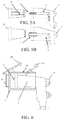
- FIG. 3A illustrates a landing bushing as taught by the present invention.
- FIG. 3B illustrates the normal operation of landing an elbow connector onto the landing bushing as taught by the present invention.
- FIGS. 4A, 4B, and 4C illustrate a standard, prior art, loadbreak elbow connectors, their manner of use, and internal components that are well known in the art.
- FIGS. 5A and 5B illustrates a second situation where the internal components of the device where the elbow is being removed from are pulled out with the elbow and cannot be landed on the device.
- FIG. 6 illustrates the insulated external parking bushing of the present invention's component parts and how they interact when in use with other existing components on a structure.
- FIG. 7 illustrates the frontal cone of a connector elbow with the damage components illustrated.
- FIG. 8 is a side image of a prototype of the present invention in development.
- FIGS. 9 and 10 are different perspective views of regular insulated parking bushings known in the prior art.
- FIGS. 11, 12, and 13 are images of the insulated external parking bushing of the present invention, which also include and illustrate a potential cut out for easier coupling or attachment to standard loadbreak elbow known in the prior art and industry.
- FIG. 14 is the Front Perspective view of the Electrical connector.
- FIG. 15 is the Rear Perspective view of the Electrical connector.
- FIG. 16 is the Front view of the Electrical connector of FIG. 1 .
- FIG. 17 is the Rear view of the Electrical connector of FIG. 1 .
- FIG. 18 is the Left side view of the Electrical connector of FIG. 1 .
- FIG. 19 is the Right side view of the Electrical connector of FIG. 1 .
- FIG. 20 is the Top view of the Electrical connector of FIG. 1 .
- FIG. 21 is the Bottom view side of the Electrical connector of FIG. 1 .
- the present invention is an insulated external parking bushing.
- the insulated external parking bushing is comprised of: a body member; a contact head extending from the body member for receiving an end of a conductor probe; a receptor sleeve extending from the body member opposite the contact head; and a conductive sleeve, including a connector cup, for receiving an end of a power cable.
- an external parking bushing is attached to the body and the receptor sleeve; and the insulated external parking bushing removeably secured to an existing external parking bushing and receptor sleeve and body, covering the contact head and the conductor probe.
- the body of the insulated external parking bushing may be made from a one piece injection mold or constructed from dielectrically rated plastics or rubber.
- the body of the insulated parking bushing is identically molded to match the parking bracket.
- the body of the insulated parking bushing is molded to add skirts for higher voltages.
- the body of the insulated parking bushing is further comprised of a cut out for easier coupling or attachment to a loadbreak elbow.
- the insulated external parking bushing is used in combination with an electrical load break elbow connector having a conductive probe for making an electrical connection between a high voltage cable and a bushing on electrical power distribution equipment.
- the insulating cover for a electrical loadbreak elbow connectors comprises a conductor element; wherein the conductor element comprises a connector socket, arranged at the first end portion, for mating with a cable plug, characterized by the connector socket being integrally formed with the middle portion, and an insulated external parking bushing removeably secured to the connector socket, covering the conductor element.
- the conductor element further comprised of: a first end portion, a second end portion, and a middle portion disposed between the first end portion and the second end portion.
- a method of protecting a loadbreak elbow connector during a malfunction includes the following steps: providing one or more loadbreak elbow connectors; connecting the loadbreak elbow connector to a bushing plug of a transformer; removing the loadbreak elbow connector from a bushing plug; pulling out the conductive components from the transformer with the loadbreak elbow connector; and securing an insulated external parking bushing to the connector loadbreak elbow connector, covering the conductive components.
- EIPB external insulated parking bushing
- FIG. 2A illustrates where an elbow is landed on the equipment.
- FIG. 2B illustrates an example of the probe and arc snuffer breaking inside the device.
- FIG. 2C illustrates a first situation where the internal components of the device 3 where the elbow connector 4 is being removed from are pulled out with the elbow and cannot be landed on the device. In this situation an insulated cap 12 is desired to cover the device 3 when the elbow connector 4 is removed.
- FIG. 3A illustrates a landing bushing as taught by the present invention.
- an eyebolt 13 is typically part of the device 3 .
- a protective cap is removed to expose the device's internals and an elbow connector 4 is attempted to be connected to the device 3 .
- FIG. 3B illustrates the normal operation of landing an elbow connector onto the landing bushing as taught by the present invention.
- the insulated external parking bushing 1 of the present invention provides a means of safely securing the LEC by bypassing the damaged components and securing the loadbreak elbow connector 4 from the outside of the elbow and covering the exposed conductive material, and then placed onto the equipment's parking stand as shown in FIG. 6 .
- the insulated external parking bushing 1 is crafted from injection molds in one solid piece from dielectrically rated plastics or rubber, with the parking bracket 19 identical to existing IPBs, with variant molds adding skirts 18 for higher voltages.
- FIGS. 4A, 4B, and 4C illustrate a standard, prior art, loadbreak elbow connectors 15 , their manner of use, and internal components, which are well known in the art and are not required to be disclosed or discussed in detail for a person of ordinary skill in the art to understand a standard loadbreak connector 15 and its corresponding internal components.
- the loadbreak elbow connectors 15 are generally comprised of a twist and push connection fitting and center alignment.
- the probe 5 provides the center alignment and a wrench hole 16 provides for securing the probe to the elbow connector 4 and creating the conductive portion 6 .
- the present invention is an insulated external parking bushing 1 as shown in FIG. 8 which is constructed out of PPC pipe.
- the insulated external parking bushing 1 in FIGS. 6 and 8 which ‘hugs’ the loadbreak elbow connector 4 .
- the present invention does not include the loadbreak elbow connector 4 , but it must be used in combination with a loadbreak elbow connector 4 .
- FIG. 7 illustrates the frontal cone of a connector elbow with the damage components illustrated.
- FIG. 7 illustrates a common situation where an elbow connector 4 has a damaged probe 22 and needs to be covered and isolated for worker safety.
- the conductive portion within the elbow connector 4 is defined as a probe 5 .
- the probe 5 consists of a conductive portion 6 and the arc follower 7 .
- the arc follower 7 is designed to extinguish an arc when de-energizing equipment under load.
- FIG. 5A shows the elbow connector 4 and probe 5 under a normal operation.
- FIG. 5B illustrates what occurs under a malfunction, where, the voltage is not conducted properly.
- a common malfunction is a swollen arc follower 7 which occurs when moisture has been allowed to migrate in between the elbow body 2 and the device 3 it is connected to resulting in heat that causes the arc follower 7 to swell and impinge on the conductor contact assembly 8 of the device 3 bushing plug 17 to which it is attached.
- FIG. 6 illustrates the insulated external parking bushing 1 of the present invention's component parts and how they interact when in use with other existing components on a structure.
- the insulated external parking bushing 1 is crafted from injection molds in one solid piece from dielectrically rated plastics or rubber, with the parking bracket 19 identical to existing IPBs, with variant molds adding skirts 18 for higher voltages.
- a first steel securing bolt can be used to secure the insulated external parking bushing 1 to a structure or provide a connection point to a hotstick 14 .
- a second bolt 21 is used to secure a loadbreak elbow 4 and retain it securely within the insulated external parking bushing 1 .
- Each bolt is comprised of a live line ring or eye bolt that can be engaged by a hotstick 14 or other device to turn the bolts 20 and 21 to tighten or loosen them as desired.
- the insulated external parking bushing 1 of the present invention works with all current hot sticks 14 known in the prior art and currently used in the industry.
- the insulated external parking bushing 1 of the present invention will require two people to operate but the advantage over standard prior art devices is that the then allows one or both of them to leave the site with the damaged elbow secured.
- one employee would be required to remain with the energized conductor held in the clear (safe) until additional help arrives.
- scenario A representing a normal operation with no malfunction
- scenario B representing what occurs when the elbow connector malfunctions due to a swollen arc follower in the current paradigm
- scenario C representing what occurs with a similar malfunction when the external insulated parking bushing of the present invention is used.
- lineman 1 opens the transformer and installs three insulated parking bushings on the transformer's parking stands. One at a time, lineman 1 unplugs each of the three loadbreak elbows and lands them on their respective insulated parking bushing while lineman 2 acts a safety observer. The business completes its upgrade and the linemen once again receive authorization to operate the three loadbreak elbows from the control center. One at a time, lineman 1 removes then elbow connectors from their parking bushings and plugs them into the transformer, restoring service.
- the elbow is now incapable of being landed on either the transformer or the insulated parking bushing.
- Lineman 2 retrieves another hotstick from the truck and unplugs the last elbow connector and lands it on its parking bushing while lineman 1 attempts to hold the damaged energized elbow connector clear of any second points of contact.
- the electricians working on the panel are instructed to stay clear of the panel in the event lineman 1 should lose control of the elbow and it make contact with the case of the transformer which is connected to the panel via its neutral.
- Lineman 1 barricades the area around the transformer as best he can to prevent possible public interaction with the situation. Lineman 1 is still holding the damaged elbow in the clear. Lineman 2 contacts the control center to inform them of the situation.
- lineman 1 While lineman 1 holds the energized elbow clear, lineman 2 installs the two external insulated parking bushings in place of the standard ones. Lineman 1 lands the malfunctioning elbow in the external bushing and secures it. Just to be safe, when they unplug the remaining elbow, they land it also on an external insulated parking bushing as it may also malfunction.
- FIGS. 9 and 10 are different perspective views of regular insulated parking bushings known in the prior art.
- FIGS. 11, 12, and 13 are images of the insulated external parking bushing 1 of the present invention, which also include and illustrate a potential cut out 23 for easier coupling or attachment to standard loadbreak elbow known in the prior art and industry.
- FIGS. 14-21 and improved embodiment of the present invention is taught.
- the new embodiment replaces the cutout 23 , with a very specific “keyhole” shaped cutout 24 design on the bottom 25 of the unit 26 .
- the narrow portion 27 of the “keyhole” shaped cutout 24 is slightly smaller then the neck of the elbow connector that is landing on it.
- the flexible material of the elbow squeezes through the narrow opening of the keyhole shaped cutout 24 and re-expands in the larger portion 28 of the keyhole shaped cutout 24 which is approximately the same size as the neck of the elbow connector that is landing on it, and able to hold the connection firmly enough that the elbow connector can then be released and secured with the threaded eyelet 21 .
Landscapes
- Connector Housings Or Holding Contact Members (AREA)
Abstract
Description
Claims (9)
Priority Applications (1)
| Application Number | Priority Date | Filing Date | Title |
|---|---|---|---|
| US16/784,187 US11024985B2 (en) | 2017-04-27 | 2020-02-06 | Insulated external parking bushing |
Applications Claiming Priority (3)
| Application Number | Priority Date | Filing Date | Title |
|---|---|---|---|
| US201762491224P | 2017-04-27 | 2017-04-27 | |
| US15/965,824 US20180316124A1 (en) | 2017-04-27 | 2018-04-27 | Insulated External Parking Bushing |
| US16/784,187 US11024985B2 (en) | 2017-04-27 | 2020-02-06 | Insulated external parking bushing |
Related Parent Applications (1)
| Application Number | Title | Priority Date | Filing Date |
|---|---|---|---|
| US15/965,824 Continuation-In-Part US20180316124A1 (en) | 2017-04-27 | 2018-04-27 | Insulated External Parking Bushing |
Publications (2)
| Publication Number | Publication Date |
|---|---|
| US20200176896A1 US20200176896A1 (en) | 2020-06-04 |
| US11024985B2 true US11024985B2 (en) | 2021-06-01 |
Family
ID=70849416
Family Applications (1)
| Application Number | Title | Priority Date | Filing Date |
|---|---|---|---|
| US16/784,187 Active US11024985B2 (en) | 2017-04-27 | 2020-02-06 | Insulated external parking bushing |
Country Status (1)
| Country | Link |
|---|---|
| US (1) | US11024985B2 (en) |
Families Citing this family (1)
| Publication number | Priority date | Publication date | Assignee | Title |
|---|---|---|---|---|
| US20180316124A1 (en) * | 2017-04-27 | 2018-11-01 | Shad Patrick Fleming | Insulated External Parking Bushing |
Citations (19)
| Publication number | Priority date | Publication date | Assignee | Title |
|---|---|---|---|---|
| US3617986A (en) * | 1969-03-06 | 1971-11-02 | Fargo Mfg Co | Transformer tap for underground applications |
| US3696321A (en) * | 1970-09-14 | 1972-10-03 | Itt | Electrical connector |
| US3766310A (en) * | 1972-08-11 | 1973-10-16 | Webster Electric Co Inc | Bushing cover |
| US3980374A (en) * | 1975-02-26 | 1976-09-14 | International Telephone And Telegraph Corporation | Separable splice connector |
| US4659164A (en) * | 1984-04-30 | 1987-04-21 | Preh Elektrofeinmechanische Werke, Jakob Preh, Nachf. Gmbh & Co. | Diode connector |
| US4677255A (en) * | 1985-02-15 | 1987-06-30 | Pirelli General Plc | Insulating shroud and sleeve for the connection between a cable end and a terminal |
| US4762501A (en) * | 1986-09-08 | 1988-08-09 | Amerace Corporation | Extended contact |
| US4955823A (en) * | 1989-10-10 | 1990-09-11 | Amerace Corporation | 600-Amp hot stick-operable screw and pin-and-socket assembled connector system |
| US5082449A (en) * | 1990-08-28 | 1992-01-21 | Amerace Corporation | Removable media injection fitting |
| US5088001A (en) * | 1990-02-23 | 1992-02-11 | Amerace Corporation | Surge arrester with rigid insulating housing |
| US5215475A (en) * | 1992-07-02 | 1993-06-01 | Amerace Corporation | Devices for use with high voltage system components for the safe expulsion of conductive moisture within such components |
| US6332785B1 (en) * | 1997-06-30 | 2001-12-25 | Cooper Industries, Inc. | High voltage electrical connector with access cavity and inserts for use therewith |
| US6790063B2 (en) * | 2002-05-16 | 2004-09-14 | Homac Mfg. Company | Electrical connector including split shield monitor point and associated methods |
| US6843685B1 (en) * | 2003-12-24 | 2005-01-18 | Thomas & Betts International, Inc. | Electrical connector with voltage detection point insulation shield |
| US7503785B2 (en) * | 2005-12-21 | 2009-03-17 | Thomas & Betts International, Inc. | Separable electrical connector component having a voltage output branch and a direct access point |
| US7704087B1 (en) * | 2004-09-03 | 2010-04-27 | Utilx Corporation | Check valve for charge tank |
| US7883356B2 (en) * | 2007-06-01 | 2011-02-08 | Cooper Technologies Company | Jacket sleeve with grippable tabs for a cable connector |
| US7985093B2 (en) * | 2008-04-04 | 2011-07-26 | Richards Manufacturing Company, A New Jersey Limited Partnership | Termination device impedance assembly |
| US8282410B2 (en) * | 2009-10-20 | 2012-10-09 | Thomas & Betts International, Inc. | Adaptor assembly for electrical connector |
-
2020
- 2020-02-06 US US16/784,187 patent/US11024985B2/en active Active
Patent Citations (19)
| Publication number | Priority date | Publication date | Assignee | Title |
|---|---|---|---|---|
| US3617986A (en) * | 1969-03-06 | 1971-11-02 | Fargo Mfg Co | Transformer tap for underground applications |
| US3696321A (en) * | 1970-09-14 | 1972-10-03 | Itt | Electrical connector |
| US3766310A (en) * | 1972-08-11 | 1973-10-16 | Webster Electric Co Inc | Bushing cover |
| US3980374A (en) * | 1975-02-26 | 1976-09-14 | International Telephone And Telegraph Corporation | Separable splice connector |
| US4659164A (en) * | 1984-04-30 | 1987-04-21 | Preh Elektrofeinmechanische Werke, Jakob Preh, Nachf. Gmbh & Co. | Diode connector |
| US4677255A (en) * | 1985-02-15 | 1987-06-30 | Pirelli General Plc | Insulating shroud and sleeve for the connection between a cable end and a terminal |
| US4762501A (en) * | 1986-09-08 | 1988-08-09 | Amerace Corporation | Extended contact |
| US4955823A (en) * | 1989-10-10 | 1990-09-11 | Amerace Corporation | 600-Amp hot stick-operable screw and pin-and-socket assembled connector system |
| US5088001A (en) * | 1990-02-23 | 1992-02-11 | Amerace Corporation | Surge arrester with rigid insulating housing |
| US5082449A (en) * | 1990-08-28 | 1992-01-21 | Amerace Corporation | Removable media injection fitting |
| US5215475A (en) * | 1992-07-02 | 1993-06-01 | Amerace Corporation | Devices for use with high voltage system components for the safe expulsion of conductive moisture within such components |
| US6332785B1 (en) * | 1997-06-30 | 2001-12-25 | Cooper Industries, Inc. | High voltage electrical connector with access cavity and inserts for use therewith |
| US6790063B2 (en) * | 2002-05-16 | 2004-09-14 | Homac Mfg. Company | Electrical connector including split shield monitor point and associated methods |
| US6843685B1 (en) * | 2003-12-24 | 2005-01-18 | Thomas & Betts International, Inc. | Electrical connector with voltage detection point insulation shield |
| US7704087B1 (en) * | 2004-09-03 | 2010-04-27 | Utilx Corporation | Check valve for charge tank |
| US7503785B2 (en) * | 2005-12-21 | 2009-03-17 | Thomas & Betts International, Inc. | Separable electrical connector component having a voltage output branch and a direct access point |
| US7883356B2 (en) * | 2007-06-01 | 2011-02-08 | Cooper Technologies Company | Jacket sleeve with grippable tabs for a cable connector |
| US7985093B2 (en) * | 2008-04-04 | 2011-07-26 | Richards Manufacturing Company, A New Jersey Limited Partnership | Termination device impedance assembly |
| US8282410B2 (en) * | 2009-10-20 | 2012-10-09 | Thomas & Betts International, Inc. | Adaptor assembly for electrical connector |
Also Published As
| Publication number | Publication date |
|---|---|
| US20200176896A1 (en) | 2020-06-04 |
Similar Documents
| Publication | Publication Date | Title |
|---|---|---|
| US20180316124A1 (en) | Insulated External Parking Bushing | |
| US6042407A (en) | Safe-operating load reducing tap plug and method using the same | |
| US7572133B2 (en) | Separable loadbreak connector and system | |
| CN103004028B (en) | Adapters for bushing lockout | |
| US9608500B2 (en) | Portable generator system for providing temporary power to an electrical-distribution system | |
| US10748728B2 (en) | Boom mountable breaker and methods of using same | |
| US11024985B2 (en) | Insulated external parking bushing | |
| Rocha et al. | New technologies, standards, and maintenance methods in spacer cable systems | |
| US20090184796A1 (en) | Enclosed Insulator Assembly for High-Voltage Distribution Systems | |
| KR102565258B1 (en) | Adaptor For Replacing Ground Transformer without Interruption of Electric Service | |
| KR102664840B1 (en) | Elbow connector separator and uninterruptible replacement device and method for aerial insulated cable using the same | |
| KR20150138770A (en) | Insulated Cover | |
| US6359765B1 (en) | Fused terminal for use with a network protector | |
| CN109378247B (en) | A 10kV anti-misclosure isolation switch lock | |
| DE730733C (en) | Device for the automatic shutdown of electrical systems in the event of insulation faults | |
| KR100757730B1 (en) | Uninterrupted construction of underground ships | |
| US3544985A (en) | Voltage-indicating device for a switch bushing stud | |
| US7548148B2 (en) | Integral transformer junction module | |
| US3463932A (en) | Underground distribution system | |
| KR102753646B1 (en) | Arrester with latch type clamp for indirect hot-line work | |
| EP2771610A1 (en) | Connection systems for electrical installations | |
| KR100940230B1 (en) | Grounding Gas Insulated Simple Water Transformer | |
| KR20250058524A (en) | Ground transformer elbow connection device | |
| CN119905972A (en) | A lightning protection device for frequency converter | |
| IT201900018803A1 (en) | Pole, particularly for a high voltage overhead electrical transmission line, equipped with a maneuvering unit and related Protection, Command and Control System |
Legal Events
| Date | Code | Title | Description |
|---|---|---|---|
| FEPP | Fee payment procedure |
Free format text: ENTITY STATUS SET TO UNDISCOUNTED (ORIGINAL EVENT CODE: BIG.); ENTITY STATUS OF PATENT OWNER: MICROENTITY |
|
| FEPP | Fee payment procedure |
Free format text: ENTITY STATUS SET TO MICRO (ORIGINAL EVENT CODE: MICR); ENTITY STATUS OF PATENT OWNER: MICROENTITY Free format text: ENTITY STATUS SET TO SMALL (ORIGINAL EVENT CODE: SMAL); ENTITY STATUS OF PATENT OWNER: MICROENTITY |
|
| STPP | Information on status: patent application and granting procedure in general |
Free format text: DOCKETED NEW CASE - READY FOR EXAMINATION |
|
| STPP | Information on status: patent application and granting procedure in general |
Free format text: NON FINAL ACTION MAILED |
|
| STPP | Information on status: patent application and granting procedure in general |
Free format text: RESPONSE TO NON-FINAL OFFICE ACTION ENTERED AND FORWARDED TO EXAMINER |
|
| STPP | Information on status: patent application and granting procedure in general |
Free format text: NOTICE OF ALLOWANCE MAILED -- APPLICATION RECEIVED IN OFFICE OF PUBLICATIONS |
|
| FEPP | Fee payment procedure |
Free format text: ENTITY STATUS SET TO MICRO (ORIGINAL EVENT CODE: MICR); ENTITY STATUS OF PATENT OWNER: MICROENTITY |
|
| STPP | Information on status: patent application and granting procedure in general |
Free format text: PUBLICATIONS -- ISSUE FEE PAYMENT RECEIVED |
|
| STPP | Information on status: patent application and granting procedure in general |
Free format text: PUBLICATIONS -- ISSUE FEE PAYMENT VERIFIED |
|
| STCF | Information on status: patent grant |
Free format text: PATENTED CASE |
|
| FEPP | Fee payment procedure |
Free format text: MAINTENANCE FEE REMINDER MAILED (ORIGINAL EVENT CODE: REM.); ENTITY STATUS OF PATENT OWNER: MICROENTITY |
|
| FEPP | Fee payment procedure |
Free format text: SURCHARGE FOR LATE PAYMENT, MICRO ENTITY (ORIGINAL EVENT CODE: M3554); ENTITY STATUS OF PATENT OWNER: MICROENTITY |
|
| MAFP | Maintenance fee payment |
Free format text: PAYMENT OF MAINTENANCE FEE, 4TH YEAR, MICRO ENTITY (ORIGINAL EVENT CODE: M3551); ENTITY STATUS OF PATENT OWNER: MICROENTITY Year of fee payment: 4 |