US11022668B2 - Magnetic resonance imaging apparatus and SAR evaluation apparatus - Google Patents
Magnetic resonance imaging apparatus and SAR evaluation apparatus Download PDFInfo
- Publication number
- US11022668B2 US11022668B2 US16/132,850 US201816132850A US11022668B2 US 11022668 B2 US11022668 B2 US 11022668B2 US 201816132850 A US201816132850 A US 201816132850A US 11022668 B2 US11022668 B2 US 11022668B2
- Authority
- US
- United States
- Prior art keywords
- local
- sars
- human body
- sar
- processing circuitry
- Prior art date
- Legal status (The legal status is an assumption and is not a legal conclusion. Google has not performed a legal analysis and makes no representation as to the accuracy of the status listed.)
- Active, expires
Links
Images


Classifications
-
- G—PHYSICS
- G01—MEASURING; TESTING
- G01R—MEASURING ELECTRIC VARIABLES; MEASURING MAGNETIC VARIABLES
- G01R33/00—Arrangements or instruments for measuring magnetic variables
- G01R33/20—Arrangements or instruments for measuring magnetic variables involving magnetic resonance
- G01R33/44—Arrangements or instruments for measuring magnetic variables involving magnetic resonance using nuclear magnetic resonance [NMR]
- G01R33/48—NMR imaging systems
- G01R33/54—Signal processing systems, e.g. using pulse sequences ; Generation or control of pulse sequences; Operator console
- G01R33/56—Image enhancement or correction, e.g. subtraction or averaging techniques, e.g. improvement of signal-to-noise ratio and resolution
- G01R33/561—Image enhancement or correction, e.g. subtraction or averaging techniques, e.g. improvement of signal-to-noise ratio and resolution by reduction of the scanning time, i.e. fast acquiring systems, e.g. using echo-planar pulse sequences
- G01R33/5611—Parallel magnetic resonance imaging, e.g. sensitivity encoding [SENSE], simultaneous acquisition of spatial harmonics [SMASH], unaliasing by Fourier encoding of the overlaps using the temporal dimension [UNFOLD], k-t-broad-use linear acquisition speed-up technique [k-t-BLAST], k-t-SENSE
- G01R33/5612—Parallel RF transmission, i.e. RF pulse transmission using a plurality of independent transmission channels
-
- G—PHYSICS
- G01—MEASURING; TESTING
- G01R—MEASURING ELECTRIC VARIABLES; MEASURING MAGNETIC VARIABLES
- G01R33/00—Arrangements or instruments for measuring magnetic variables
- G01R33/20—Arrangements or instruments for measuring magnetic variables involving magnetic resonance
- G01R33/28—Details of apparatus provided for in groups G01R33/44 - G01R33/64
- G01R33/288—Provisions within MR facilities for enhancing safety during MR, e.g. reduction of the specific absorption rate [SAR], detection of ferromagnetic objects in the scanner room
-
- G—PHYSICS
- G01—MEASURING; TESTING
- G01R—MEASURING ELECTRIC VARIABLES; MEASURING MAGNETIC VARIABLES
- G01R33/00—Arrangements or instruments for measuring magnetic variables
- G01R33/20—Arrangements or instruments for measuring magnetic variables involving magnetic resonance
- G01R33/28—Details of apparatus provided for in groups G01R33/44 - G01R33/64
- G01R33/38—Systems for generation, homogenisation or stabilisation of the main or gradient magnetic field
- G01R33/385—Systems for generation, homogenisation or stabilisation of the main or gradient magnetic field using gradient magnetic field coils
-
- G—PHYSICS
- G01—MEASURING; TESTING
- G01R—MEASURING ELECTRIC VARIABLES; MEASURING MAGNETIC VARIABLES
- G01R33/00—Arrangements or instruments for measuring magnetic variables
- G01R33/20—Arrangements or instruments for measuring magnetic variables involving magnetic resonance
- G01R33/44—Arrangements or instruments for measuring magnetic variables involving magnetic resonance using nuclear magnetic resonance [NMR]
- G01R33/48—NMR imaging systems
- G01R33/54—Signal processing systems, e.g. using pulse sequences ; Generation or control of pulse sequences; Operator console
- G01R33/56—Image enhancement or correction, e.g. subtraction or averaging techniques, e.g. improvement of signal-to-noise ratio and resolution
- G01R33/561—Image enhancement or correction, e.g. subtraction or averaging techniques, e.g. improvement of signal-to-noise ratio and resolution by reduction of the scanning time, i.e. fast acquiring systems, e.g. using echo-planar pulse sequences
- G01R33/5613—Generating steady state signals, e.g. low flip angle sequences [FLASH]
Definitions
- Embodiments described herein relate to a magnetic resonance imaging apparatus and an SAR evaluation apparatus.
- An input signal concerning a radio frequency (RF) pulse used for imaging in magnetic resonance imaging (hereinafter referred to as “MRI”) is set to make a specific absorption rate (SAR) obtained in a subject fall below a reference value.
- the SAR is an index of energy of an RF pulse absorbed in body tissue of the subject, and is an index relating to safety of the subject.
- the calculation of SARs may take time.
- composite electric field vectors which are composites of electric field vectors generated at points in the subject by a plurality of RF coils, into a plurality of clusters in accordance with the degrees of similarity of the composite electric field vectors, and calculating SARs at representative points of the respective clusters.
- maximum local SAR the position corresponding to the locally maximum SAR (hereinafter referred to as a “maximum local SAR”) depends on the human body shape; however, the above method does not take the human body shape into consideration. Therefore, the maximum local SAR estimated by the above method may be undervalued in comparison with the actual maximum local SAR.
- FIG. 1 is a diagram showing a configuration of the magnetic resonance imaging apparatus in the present embodiment.
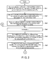
- FIG. 2 is a diagram showing an example of the steps of the evaluation point determination processing in the present embodiment.
- FIG. 3 is a diagram showing an example of the steps performed by the processing circuitry realizing the evaluation point determination processing in the present embodiment.
- FIG. 4 is a diagram showing an example of the change in the total number of evaluation points with respect to the total repetition number in the evaluation point determination processing in the present embodiment.
- FIG. 5 is a diagram showing an example of comparison between the total number of evaluation points obtained by the evaluation point determination processing in the present embodiment and the total number of evaluation points obtained by conventional processing.
- FIG. 6 is a diagram showing an example of the steps of the human body model selection processing and SAR estimation processing in the present embodiment.
- FIG. 7 is an example of the distribution of local SAR estimate values estimated by the SAR estimation processing with respect to the maximum local SARs corresponding to a plurality of evaluation points determined by the evaluation point determination processing in the present embodiment.
- a magnetic resonance imaging apparatus includes processing circuitry and imaging control circuitry.
- the processing circuitry selects a human body model corresponding to a subject from a plurality of human body models.
- the processing circuitry estimates a plurality of local specific absorption rates (SARs) at a plurality of evaluation points determined using the selected human body model, based on the selected human body model and an amplitude and/or phase of the RF pulse in an imaging protocol for magnetic resonance imaging scheduled to be performed on the subject.
- the processing circuitry determines whether or not the estimated local SARs fall below a local reference value.
- the imaging control circuitry executes the imaging protocol by using an amplitude and phase of the RF pulse which make the local SARs fall below the local reference value.
- a purpose is to estimate SARs in a short time without undervaluing them.
- MRI apparatus magnetic resonance imaging apparatus
- structural elements having approximately the same function and configuration will be assigned with the same reference symbol, and a repetitive description will be given only where necessary.
- FIG. 1 is a diagram showing a configuration of the MRI apparatus 100 in the present embodiment.
- the MRI apparatus 100 includes a static magnetic field magnet 101 , a gradient coil 103 , a gradient magnetic field power supply 105 , a bed 107 , bed control circuitry 109 , transmission circuitry (transmitter) 113 , a transmitter coil 115 , a receiver coil 117 , reception circuitry (receiver) 119 , imaging control circuitry (imaging controller) 121 , a bus 123 , an interface (input section) 125 , a display 127 , a storage apparatus (memory) 129 , and processing circuity (processor) 131 .
- the MRI apparatus 100 may include a hollow cylindrical shim coil between the static magnetic field magnet 101 and the gradient coil 103 .
- the static magnetic field magnet 101 is a hollow approximately-cylindrical magnet.
- the static magnetic field magnet 101 is not necessarily approximately-cylindrical, and may be of an open type.
- the static magnetic field magnet 101 generates a uniform static magnetic field in the inner space.
- a superconducting magnet or the like is used as the static magnetic field magnet 101 .
- the gradient coil 103 is a hollow cylindrical coil.
- the gradient coil 103 is provided inside the static magnetic field magnet 101 .
- the gradient coil 103 is a combination of three coils corresponding to X, Y, Z-axes orthogonal to one another.
- the Z-axis direction is the same direction as the direction of the static magnetic field.
- the Y-axis direction is the vertical direction, and the X-axis direction is perpendicular to the Z-axis and the Y-axis.
- the three coils in the gradient coil 103 are individually supplied with a current from the gradient magnetic field power supply 105 , and generate gradient magnetic fields whose magnetic field intensity changes along the respective X, Y, and Z-axes.
- the gradient magnetic fields of the X, Y, and Z-axes generated by the gradient coil 103 correspond respectively to, for example, a slice selection gradient magnetic field, a phase encoding gradient magnetic field, and a frequency encoding gradient magnetic field (also referred to as a readout gradient magnetic field).
- the slice selection gradient magnetic field is used to determine an imaging slice at will.
- the phase encoding gradient magnetic field is used to change the phase of a magnetic resonance (hereinafter referred to as “MR”) signal in accordance with the spatial position.
- MR magnetic resonance
- the frequency encoding gradient magnetic field is used to change the frequency of an MR signal in accordance with the spatial position.
- the gradient magnetic field power supply 105 is a power supply device that supplies a current to the gradient coil 103 under the control of the imaging control circuitry 121 .
- the bed 107 is an apparatus including a top plate 1071 on which the subject P is placed.
- the bed 107 inserts the top plate 1071 on which the subject P is placed into a bore 111 under the control of the bed control circuitry 109 .
- the bed 107 is installed in an examination room in which the present MRI apparatus 100 is installed so that, for example, its longitudinal direction is parallel to the central axis of the static magnetic field magnet 101 .
- the bed control circuitry 109 is circuitry that controls the bed 107 .
- the bed control circuitry 109 drives the bed 107 in response to operator's instructions via the interface 125 to move the top plate 1071 in the longitudinal direction and vertical direction.
- the transmission circuitry 113 supplies a radio frequency pulse (RF pulse) modulated with the Larmor frequency to the transmitter coil 115 under the control of the imaging control circuitry 121 .
- RF pulse radio frequency pulse
- the transmitter coil 115 is an RF coil provided inside the gradient coil 103 .
- the transmitter coil 115 is supplied with the RF pulse from the transmission circuitry 113 and generates a transmit RF wave corresponding to a radio frequency magnetic field.
- the transmitter coil 115 is, for example, a whole body coil (WB coil) including a plurality of coil elements.
- the WB coil may be used as a transmitter/receiver coil.
- the transmitter coil 115 may also be a WB coil formed by a single coil.
- the receiver coil 117 is an RF coil provided inside the gradient coil 103 .
- the receiver coil 117 receives an MR signal that the radio frequency magnetic field causes the subject P to emit.
- the receiver coil 117 outputs the received MR signal to the reception circuitry 119 .
- the receiver coil 117 is a coil array including, for example, one or more, typically, a plurality of coil elements.
- FIG. 1 shows the transmitter coil 115 and the receiver coil 117 as separate RF coils; however, the transmitter coil 115 and the receiver coil 117 may be embodied as an integrated transmitter/receiver coil.
- the transmitter/receiver coil corresponds to an imaging target of the subject P, and is a local transmitter/receiver RF coil, such as a head coil.
- the reception circuitry 119 generates a digital MR signal (hereinafter referred to as “MR data”) based on the MR signal output from the receiver coil 117 under the control of the imaging control circuitry 121 . Specifically, the reception circuitry 119 performs various types of signal processing on the MR signal output from the receiver coil 117 , and then performs analog-to-digital (A/D) conversion on the data subjected to the various types of signal processing. The reception circuitry 119 performs sampling on the A/D-converted data. The reception circuitry 119 thereby generates MR data. The reception circuitry 119 outputs the generated MR data to the imaging control circuitry 121 .
- MR data digital MR signal
- the imaging control circuitry 121 controls, for example, the gradient magnetic field power supply 105 , the transmission circuitry 113 , and the reception circuitry 119 in accordance with an imaging protocol output from the processing circuitry 131 , and performs imaging on the subject P.
- the imaging protocol includes various pulse sequences corresponding to the examination.
- the imaging protocol defines the magnitude of the current supplied from the gradient magnetic field power supply 105 to the gradient coil 103 , timing of the supply of the current from the gradient magnetic field power supply 105 to the gradient coil 103 , the magnitude and time width of the RF pulse supplied from the transmission circuitry 113 to the transmitter coil 115 , timing of the supply of the RF pulse from the transmission circuitry 113 to the transmitter coil 115 , and timing of reception of the MR signal at the receiver coil 117 , etc.
- the imaging control circuitry 121 performs, for example, a pre-scan which is performed before a main scan on the subject P to obtain a transmit RF magnetic field distribution (also referred to as a “B 1 map”) formed by transmit RF wave(s) transmitted from a plurality of coil elements or a single coil element of the transmitter coil 115 .
- the imaging control circuitry 121 causes the storage apparatus 129 to store the obtained B 1 map.
- the bus 123 is a transmission path for transmitting data between the interface 125 , the display 127 , the storage apparatus 129 , and the processing circuitry 131 .
- the bus 123 may be connected via, for example, a network to various physiological signal measuring devices, an external storage apparatus, and various modalities.
- the interface 125 includes a circuit that receives various instructions and information inputs from the operator.
- the interface 125 includes a circuit relating to, for example, a pointing device such as a mouse, or an input device such as a keyboard.
- the circuit included in the interface 125 is not limited to a circuit relating to a physical operational component, such as a mouse or a keyboard.
- the interface 125 may include an electrical signal processing circuit which receives an electrical signal corresponding to an input operation from an external input device provided separately from the present MRI apparatus 100 and outputs the received electrical signal to various circuits.
- the display 127 displays, for example, various MR images generated by an image generation function 1313 , and various types of information relating to imaging and image processing, under the control of a system control function 1311 in the processing circuitry 131 .
- the display 127 also displays a specific absorption rate (SAR) estimated by an SAR estimation function 1319 .
- the display 127 may display a warning when the SAR exceeds a reference value.
- the display 127 is, for example, a display device, such as a CRT display, a liquid crystal display, an organic EL display, an LED display, a plasma display, or any other display or monitor known in the relevant technical field.
- the storage apparatus 129 stores, for example, MR data filled in the k space via the image generation function 1313 , image data generated by the image generation function 1313 , and the B 1 map.
- the storage apparatus 129 stores, for example, various imaging protocols, and an imaging condition including a plurality of imaging parameters defining each imaging protocol.
- the storage apparatus 129 also stores a plurality of reference values relating to the SAR.
- the reference value is also called a restraining value, or a limiting value.
- the reference values relating to the SAR are a local reference value and a whole body reference value.
- the local reference value is a value for determining whether or not a local SAR estimated by the SAR estimation function 1319 (hereinafter referred to as a “local SAR”) exceeds a safe limit.
- the whole body reference value is a value for determining whether or not an average SAR over the whole body estimated by the SAR estimation function 1319 (hereinafter referred to as a “whole body average SAR”) exceeds a safe limit.
- the storage apparatus 129 stores programs corresponding to various functions performed by the processing circuitry 131 .
- the storage apparatus 129 is, for example, a semiconductor memory element, such as a random access memory (RAM) or a flash memory, a hard disk drive, a solid state drive, or an optical disk.
- the storage apparatus 129 may also be, for example, a drive that performs writing and reading of various types of information on a CD-ROM drive, a DVD drive, or a portable memory medium such as a flash memory.
- the processing circuitry 131 includes, as hardware resources, a processor and a memory such as a read-only memory (ROM) and a RAM, which are not shown, and collectively controls the present MRI apparatus 100 .
- the processing circuitry 131 has a system control function 1311 , an image generation function 1313 , an evaluation point determination function 1315 , a human body model selection function 1317 , and an SAR estimation function 1319 .
- Various functions performed by the system control function 1311 , the image generation function 1313 , the evaluation point determination function 1315 , the human body model selection function 1317 , and the SAR estimation function 1319 are stored in the storage apparatus 129 in the form of a program executable by a computer.
- the processing circuitry 131 is a processor that reads programs corresponding to the various functions from the storage apparatus 129 and executes them to realize functions corresponding to the programs.
- the processing circuitry 131 that has read the programs have, for example, the functions shown in the processing circuitry 131 in FIG. 1 .
- FIG. 1 illustrates the case where the various functions are realized in a single processing circuit 131 ; however, the processing circuitry 131 may be constituted by a combination of a plurality of independent processors, and the functions may be realized by the processors executing the programs. In other words, the above-described functions may be configured as programs, and executed by a single processing circuit; alternatively, a specific function may be implemented in a dedicated independent program execution circuit.
- the system control function 1311 , image generation function 1313 , evaluation point determination function 1315 , human body model selection function 1317 , and SAR estimation function 1319 included in the processing circuitry 131 are examples of a system controller, an image generation section, an evaluation point determination section, a human body model selection section, and an SAR estimation section, respectively.
- processor means, for example, a circuit such as a central processing unit (CPU), a graphics processing unit (GPU), an application specific integrated circuit (ASIC), or a programmable logic device (e.g., a simple programmable logic device (SPLD), a complex programmable logic device (CPLD), or a field programmable gate array (FPGA)).
- CPU central processing unit
- GPU graphics processing unit
- ASIC application specific integrated circuit
- SPLD simple programmable logic device
- CPLD complex programmable logic device
- FPGA field programmable gate array
- the processor realizes various functions by reading and executing programs stored in the storage apparatus 129 .
- the programs may be directly integrated in the circuit of the processor, instead of being stored in the storage apparatus 129 .
- the processor realizes functions by reading and executing programs integrated in the circuit.
- the bed control circuitry 109 , the transmission circuitry 113 , the reception circuitry 119 , and the imaging control circuitry 121 , etc. are constituted by an electronic circuit such as the above-described processor.
- the processing circuitry 131 collectively controls the MRI apparatus 100 by the system control function 1311 . Specifically, the processing circuitry 131 reads the system control program stored in the storage apparatus 129 and loads it in the memory, and controls each circuitry of the present MRI apparatus 100 in accordance with the expanded system control program. For example, the processing circuitry 131 reads an imaging protocol from the storage apparatus 129 by the system control function 1311 based on an imaging condition input by the operator via the interface 125 . The processing circuitry 131 may generate the imaging protocol based on the imaging condition. The processing circuitry 131 transmits the imaging protocol to the imaging control circuitry 121 , and controls imaging on the subject P.
- the processing circuitry 131 fills MR data by the image generation function 1313 in the readout direction of the k space in accordance with the intensity of the readout gradient magnetic field.
- the processing circuitry 131 performs the Fourier transform on the MR data filled in the k space and generates an MR image.
- the processing circuitry 131 outputs the MR image to the display 127 and the storage apparatus 129 .
- the evaluation point determination function 1315 the human body model selection function 1317 , and the SAR estimation function 1319 , etc. in the present embodiment will be described in detail.
- the following description is provided assuming that the transmitter coil 115 includes a plurality of coil elements; however, the transmitter coil 115 may be a single coil.
- the storage apparatus 129 stores a plurality of human body models used for estimation of the local SARs and the whole body average SAR.
- the human body models are distinguished by representative body shapes and builds classified according to subject information such as the sex, age, height, and weight of the subject P.
- the human body models are each a numerical human body model.
- the numerical human body model simulates a human body shape and distribution of various physicality values contributing to calculation of SARs, such as density distribution and conductivity distribution, by a plurality of voxels in accordance with the anatomical structure of various tissues in a human body.
- the storage apparatus 129 stores each of a plurality of human body models in association with a plurality of evaluation points.
- the evaluation point is a position where a local SAR is estimated (calculated) by the SAR estimation function 1319 on a human body model corresponding to the subject P of a plurality of human body models.
- the evaluation point is determined using each human body model by the evaluation point determination function 1315 . The determination of the evaluation point will be described later in the description of evaluation point determination processing.
- the storage apparatus 129 stores an overevaluation coefficient u.
- the overevaluation coefficient u is used when the evaluation point is determined by the evaluation point determination function 1315 .
- the overevaluation coefficient u is also used when the local SARs and the whole body average SAR are estimated by the SAR estimation function 1319 .
- the overevaluation coefficient u is calculated by multiplying a local SAR assumed to be maximum regarding each of the human body models by a predetermined percentage.
- the predetermined percentage is, for example, 0.1%, 0.5%, 1%, 5%, or 10%, is set by default, and is stored in the storage apparatus 129 .
- the predetermined percentage is appropriately changed or set by operator's instructions via the interface 125 .
- the overevaluation coefficient u may be calculated by, for example, the following procedure: First, a plurality of electric field distributions in a steady state generated by a plurality of coil elements of the RF coil are calculated by the processing circuitry 131 realizing the evaluation point determination function 1315 . Then, the amplitude and phase of the RF pulse are set by the processing circuitry 131 to realize a sum electric field distribution obtained by bringing in phase and summing the calculated electric field distributions. Subsequently, a plurality of local SARs corresponding to a plurality of points of the whole body of each of a plurality of human body models are calculated using the set amplitude and phase and each of the human body models.
- an overevaluation coefficient u is calculated by multiplying the maximum local SAR of the calculated local SARs by a predetermined percentage, and is stored in the storage apparatus 129 .
- the overevaluation coefficient u is not necessarily calculated by the above procedure, and may be stored in the storage apparatus 129 as a default value.
- the storage apparatus 129 stores the total number (hereinafter referred to as a “total repetition number”) k of times calculation is repeated in the evaluation point determination processing performed by the evaluation point determination function 1315 .
- the total repetition number k may be appropriately input or set by operator's instructions via the interface 125 .
- the storage apparatus 129 stores the initial amplitude A 1 and initial phase ⁇ 1 of the RF pulse used in the first calculation of the repeated calculation in the evaluation point determination processing.
- the initial amplitude A 1 and initial phase ⁇ 1 may be the amplitude and phase used for calculation of the overevaluation coefficient u, or may be the amplitude and phase which make the RF pulse maximum in the pulse sequence.
- the initial amplitude A 1 and initial phase ⁇ 1 may also be input or set in accordance with operator's instructions via the interface 125 .
- the storage apparatus 129 stores evaluation point P m extracted by the evaluation point determination processing, and the number (hereinafter referred to as a “repetition number”) n of times the calculation is repeated in the evaluation point determination processing.
- the identifier m of evaluation point P m and the repetition number n are natural numbers.
- the storage apparatus 129 stores, for example, a program (hereinafter referred to as an “electromagnetic field analysis program”) concerning electromagnetic field analysis used for estimation of SARs in the evaluation point determination function 1315 and SAR estimation function 1319 .
- the storage apparatus 129 stores default values of the amplitude and phase of the RF pulse for each of the imaging protocols.
- the amplitude and phase of the RF pulse correspond to the pTx pulse weight in the parallel transmission.
- the storage apparatus 129 may store the electric field distribution at the evaluation point of the electric field distribution in the steady state generated by supplying a sine wave signal corresponding to the amplitude and phase of the RF pulse to each of a plurality of coil elements, in association with the evaluation point.
- the processing circuitry 131 realizing the evaluation point determination function 1315 repeats calculation of local SARs while varying the combination of the amplitude and phase of the RF pulse for each of the human body models to determine, as an evaluation point on each of the human body models, a position corresponding to the maximum local SAR of a plurality of local SARs repeatedly calculated.
- the steps of the evaluation point determination processing will be described with reference to FIGS. 2 and 3 .
- FIGS. 2 and 3 show an example of the steps of the evaluation point determination processing.
- the steps in FIGS. 2 and 3 are performed for each of all the human body models.
- the steps in FIGS. 2 and 3 are performed for each of MRI apparatuses including bores 111 in different shapes, for example, for each of the models of MRI apparatuses.
- the overevaluation coefficient u, the total repetition number k, and the amplitude A n and phase ⁇ n of the RF pulse are set, and 1 is applied to the initial value of n and to the initial value of m for evaluation point P m .
- the processing circuitry 131 reads, from the storage apparatus 129 , the overevaluation coefficient u, the total repetition number k, the initial amplitude A 1 and initial phase ⁇ 1 of the RF pulse, and the human body model used in the evaluation point determination processing.
- the processing circuitry 131 reads the electromagnetic field analysis program from the storage apparatus 129 .
- the processing circuitry 131 calculates a plurality of local SARs corresponding respectively to a plurality of points of the read human body model by using the read initial amplitude A 1 and initial phase ⁇ 1 , and human body model. Specifically, the processing circuitry 131 inputs the initial amplitude A 1 and initial phase ⁇ 1 , and human body model into the electromagnetic field analysis program. At this time, the processing circuitry 131 functions as an electromagnetic field simulator. The processing circuitry 131 functioning as the electromagnetic field simulator calculates a plurality of SARs corresponding to a plurality of points of the human body model.
- the human body model reflects a body type and build of a human body; therefore, the calculated local SARs take values reflecting a human body shape.
- the method for calculating a plurality of local SARs is not limited to the above-described method using the electromagnetic field simulator.
- a plurality of local SARs may be calculated by the following procedure: First, the processing circuitry 131 calculates a plurality of electric field distributions in the steady state generated by a plurality of coil elements of the RF coil on the human body model by using the initial amplitude A 1 and initial phase ⁇ 1 , and the human body model. Then, the processing circuitry 131 calculates a plurality of local SARs corresponding to a plurality of points of the human body model by using the electric field distributions and the human body model.
- an electric field distribution changing method a plurality of electric field distributions in the steady state can be changed in proportion to the change in the amplitude and phase of the RF pulse, thus SARs can be calculated faster than in the above-described method using the electromagnetic field simulator.
- the processing circuitry 131 identifies the first maximum local SAR which is the maximum local SAR of the calculated local SARs.
- the processing circuitry 131 identifies a position corresponding to the first maximum local SAR (hereinafter referred to as a first maximum local position).
- the processing circuitry 131 stores the first maximum local position in its own memory as evaluation point P 1 . Namely, in the first calculation of the repeated calculation in the evaluation point determination processing, the maximum local SAR is extracted from the calculated local SARs, and the position corresponding to the extracted maximum local SAR is determined as evaluation point P 1 .
- the processing circuitry 131 may further determine, as evaluation points, positions corresponding to first local SARs identified from the calculated local SARs in descending order.
- the processing circuitry 131 stores the determined evaluation points in its own memory.
- the processing circuitry 131 may calculate the overevaluation coefficient u by multiplying the first maximum local SAR by a predetermined percentage in this step. In this case, the overevaluation coefficient u is not read in step Sa 1 , and the calculated overevaluation coefficient u is stored in the storage apparatus 129 .
- the processing circuitry 131 increments the repetition number n. Namely, the processing circuitry 131 replaces the repetition number n with n+1.
- the processing circuitry 131 sets a combination of the amplitude A n and phase ⁇ n different from the combination of the amplitude A n ⁇ 1 and phase ⁇ n ⁇ 1 of the RF pulse. Namely, in the n-th or subsequent calculation of the repeated calculation of local SARs, the processing circuitry 131 sets a combination of the amplitude A n and phase ⁇ n different from any of the combinations of the amplitude A n ⁇ 1 and phase ⁇ n ⁇ 1 used in the first to (n ⁇ 1)-th calculations. For example, the processing circuitry 131 randomly sets the combination of amplitude A n and phase ⁇ n to be different from the combination of amplitude A n ⁇ 1 and phase ⁇ n ⁇ 1 .
- the amplitude A n is randomly set within the range between 0 and 1
- the phase ⁇ n is randomly set within the range between 0 and 360 degrees.
- the amplitude A n and phase are not necessarily randomly set, and may be set, for example, in descending order of the RF pulse in the pulse sequence.
- the processing circuitry 131 re-calculates a plurality of local SARs corresponding respectively to a plurality of points of the human body model by using the set amplitude A n and phase ⁇ n , and the human body model.
- the re-calculation of a plurality of local SARs is the same as step Sa 2 when the electromagnetic field simulator is used, and descriptions thereof will be omitted.
- the processing circuitry 131 first calculates the difference value between amplitude A n ⁇ 1 and and amplitude A n and that between phase ⁇ n ⁇ 1 and phase ⁇ n . Then, the processing circuitry 131 changes the electric field distributions used in the (n ⁇ 1)-th calculation of the repeated calculation in accordance with the calculated difference values. Subsequently, the processing circuitry 131 re-calculates a plurality of local SARs by using the changed electric field distributions and the human body model.
- the processing circuitry 131 identifies the n-th maximum local SAR (MaxSAR) of the re-calculated local SARs and the position of the n-th maximum local SAR (hereinafter referred to as the “n-th maximum local position”). Namely, the processing circuitry 131 extracts the n-th maximum local SAR, which is the maximum local SAR, from the re-calculated local SARs. The processing circuitry 131 may identify a plurality of n-th local SARs from the re-calculated local SARs in descending order, and identify positions of the identified n-th local SARs.
- the processing circuitry 131 identifies a plurality of local SARs corresponding to the positions stored in the second to (n ⁇ 1)-th calculations of the repeated calculation from the re-calculated local SARs. Then, the processing circuitry 131 extracts the maximum value (MaxSAR ext ) from the identified local SARs. Namely, the processing circuitry 131 extracts the maximum value (MaxSAR ext ) of the maximum local SARs corresponding to a plurality of evaluation points extracted and stored in the repeated calculation. Next, the processing circuitry 131 calculates an added value (MaxSAR ext +u) by adding the overevaluation coefficient u to the maximum value (MaxSAR ext ). For example, the processing circuitry 131 calculates the added value by adding the overevaluation coefficient u to the local SAR at evaluation point P m .
- the processing circuitry 131 compares the n-th maximum local SAR with the added value. When the n-th maximum local SAR is larger than the added value (MaxSAR ext +u ⁇ MaxSAR: Yes in step Sa 8 ), the processing circuitry 131 performs the processing of step Sa 9 . When the n-th maximum local SAR is equal to or smaller than the added value (MaxSAR ext +u ⁇ MaxSAR: No in step Sa 8 ), the processing circuitry 131 performs the processing of step Sa 11 .
- the processing circuitry 131 increments identifier m of evaluation point P m . Namely, the processing circuitry 131 replaces identifier m of evaluation point P m with m+1.
- the processing circuitry 131 stores the n-th maximum local position in its own memory as evaluation point P m+1 together with the n-th maximum local SAR.
- the processing circuitry 131 may store the positions of a plurality of identified n-th local SARs as further evaluation points together with the identified n-th local SARs.
- FIG. 4 shows an example of the change in the total number of evaluation points with respect to the total repetition number k.
- the total repetition number k may be set by the processing circuitry 131 or by default in accordance with the magnitude of the overevaluation coefficient u.
- the processing in step Sa 11 relates to determination on the repeated calculation in the evaluation point determination processing; however, the repeated calculation is not necessarily stopped based on the above determination.
- the processing circuitry 131 may stop the repeated calculation based on the convergence condition of the increase in the number of evaluation points in the repeated calculation.
- the processing circuitry 131 performs the processing of step Sa 12 .
- the processing circuitry 131 performs the processing of step Sa 12 when the total number of evaluation points does not increase even if a predetermined repetition number of calculations set as a threshold (hereinafter referred to as a number threshold) have been performed.
- a predetermined repetition number of calculations set as a threshold hereinafter referred to as a number threshold
- the number threshold is stored in the storage apparatus 129 .
- the number threshold may be set by the processing circuitry 131 or by default in accordance with the magnitude of the overevaluation coefficient u.
- the processing circuitry 131 causes the storage apparatus 129 to store the positions of a plurality of evaluation points stored in its own memory in association with a human body model.
- the evaluation value determination processing from step Sa 1 to step Sa 12 may be performed to determine evaluation points when a new human body model is stored in the storage apparatus 129 via, for example, a network.
- the processing circuitry 131 determines a plurality of positions corresponding to a plurality of stored maximum local SARs as evaluation points on each of a plurality of human body models, and causes the storage apparatus 129 to store the determined evaluation points together with the human body model as for example, a look-up table (LUT).
- LUT look-up table
- FIG. 5 shows an example of comparison between the total number of evaluation points obtained by the evaluation point determination processing according to the present embodiment and the total number of evaluation points obtained by conventional processing. As shown in FIG. 5 , the total number of evaluation points in the present embodiment is much smaller than the one obtained by the conventional processing.
- the reduction in evaluation points contributes to a reduction in the time required for estimation of local SARs used when determining the amplitude and phase of the RF pulse in an imaging protocol.
- the processing circuitry 131 realizing the human body model selection function 1317 selects a human body model corresponding to the subject P from a plurality of human body models. For example, the processing circuitry 131 selects a human body model corresponding to the body shape of the subject P from a plurality of human body models. Specifically, the processing circuitry 131 selects a human body model used by the SAR estimation function 1319 from a plurality of human body models based on subject information on the subject P and/or a body shape image of the subject P obtained by an optical camera (not shown). The optical camera is installed, for example, in the examination room in which the present MRI apparatus 100 is installed, on a stand of the present MRI apparatus 100 , or at the entrance of the examination room.
- human body model selection processing The processing relating to selection of a human body model (hereinafter referred to as “human body model selection processing”) will be described in detail later.
- the processing circuitry 131 realizing the SAR estimation function 1319 estimates local SARs at a plurality of evaluation points determined using the human body model. Specifically, the processing circuitry 131 repeatedly calculates a plurality of local SARs at a plurality of evaluation points while changing the amplitude and/or phase until the estimated local SARs fall below the local reference value.
- the processing circuitry 131 calculates a whole body average SAR by using the human body model and the amplitude and phase which make the local SARs fall below the local reference value, and repeatedly calculates a plurality of local SARs at a plurality of evaluation points and a whole body average SAR while changing the amplitude and/or phase until the local SARs fall below the local reference value and the whole body average SAR falls below the whole body reference value.
- SAR estimation processing processing relating to the SAR estimation function 1319
- human body model selection processing will be described with reference to FIG. 6 .
- FIG. 6 shows an example of the steps of the SAR estimation processing and the human body model selection processing.
- the processing circuitry 131 selects a human body model having a similar body shape to the subject P from a plurality of human body models by the human body model selection function 1317 . Specifically, the processing circuitry 131 identifies a plurality of human body models having similar body shapes to the subject P in accordance with an image recognition result of the body shape in the body shape image of the subject P and subject information on the subject P. The processing circuitry 131 displays the names of the identified human body models on the display 127 in a list form. The processing circuitry 131 may display thumbnail images of the identified human body models on the display 127 . When a human body model name or a human body model thumbnail image is selected by operator's instructions through the interface 125 , the processing circuitry 131 sets the selected human body model as a human body model used by the SAR estimation function 1319 .
- the processing circuitry 131 reads from the storage apparatus 129 a plurality of evaluation points associated with the selected human body model, the selected human body model, and the electric field distributions at the evaluation points.
- the processing in step Sb 1 and step Sb 2 corresponds to the human body model selection processing.
- the processing circuitry 131 Upon selection of an imaging protocol in accordance with operator's instructions via the interface 125 , the processing circuitry 131 reads an amplitude and phase from the storage apparatus 129 as default values.
- the imaging control circuitry 121 obtains a B 1 map formed by transmit RF waves transmitted from a plurality of coil elements, in a step preceding the present step by, for example, a pre-scan on the subject P, the processing circuitry 131 may set the amplitude and phase used for estimation of the local SARs and the whole body average SAR by changing the amplitude and phase read by using the B 1 map obtained before the main scan on the subject P.
- the processing circuitry 131 estimates a plurality of local SARs at a plurality of evaluation points by using the set or read amplitude and phase, the human body model, and the electric field distributions.
- the method for estimating local SARs is the same as the calculation in the processing of step Sa 2 , and descriptions thereof will be omitted.
- the processing circuitry 131 selects the maximum local SAR from a plurality of local SARs.
- the processing circuitry 131 calculates a local SAR estimate value by adding the overevaluation coefficient u to the selected local SAR.
- the processing circuitry 131 reads the local reference value from the storage apparatus 129 .
- the processing circuitry 131 compares the calculated local SAR estimate value with the local reference value. When the local SAR estimate value is equal to or larger than the local reference value (No in step Sb 6 ), the processing circuitry 131 performs the processing of step Sb 7 . When the local SAR estimate value is smaller than the local reference value (Yes in step Sb 6 ), the processing circuitry 131 performs the processing of step Sb 8 .
- the processing circuitry 131 resets the amplitude and/or phase of the RF pulse by the SAR estimation function 1319 .
- the processing circuitry 131 decreases the amplitude set in step Sb 3 .
- the processing circuitry 131 may change the phase set in step Sb 3 .
- the processing circuitry 131 may decrease the amplitude set in step Sb 3 and change the phase set in step Sb 3 .
- the processing circuitry 131 repeats the processing from step Sb 4 to step Sb 6 .
- the repeated processing in step Sb 4 corresponds to the processing in step Sa 5 .
- the processing circuitry 131 estimates the whole body average SAR with the electromagnetic field analysis program by using the amplitude and phase set in step Sb 3 and the selected human body model.
- the method for estimating the whole body average SAR is the same as the calculation in the processing of step Sa 2 , and descriptions thereof will be omitted.
- the processing circuitry 131 reads the whole body reference value from the storage apparatus 129 .
- the processing circuitry 131 compares the estimated whole body average SAR with the whole body reference value. When the whole body average. SAR is equal to or larger than the whole body reference value (No in step Sb 9 ), the processing circuitry 131 performs the processing of step Sb 7 . When the whole body average SAR is smaller than the whole body reference value (Yes in step Sb 9 ), the SAR estimation processing ends. In this case, the processing circuitry 131 determines the amplitude and phase set in step Sb 3 or Sb 7 as the amplitude and phase of the RF pulse for the imaging protocol.
- step Sb 9 when instructions to start magnetic resonance imaging are input in accordance with operator's instructions via the interface 125 , the imaging control circuitry 121 executes the imaging protocol using the amplitude and phase determined by the processing of step Sb 9 . Namely, the imaging control circuitry 121 executes the imaging protocol by using the amplitude and phase of the RF pulse which make the local SARs estimated by the SAR estimation function 1319 fall below the local reference value, and make the estimated whole body average SAR fall below the whole body reference value.
- FIG. 7 is a diagram showing an example of the distribution of local SAR estimate values estimated by the SAR estimation processing with respect to the maximum local SARs corresponding to a plurality of evaluation points determined by the evaluation point determination processing.
- evaluation points are determined without undervaluing the local SAR estimate values in setting of the amplitude and phase of the transmission RF pulse in an imaging protocol, i.e., in setting of the pTx pulse weight.
- the MRI apparatus 100 can select a human body model corresponding to the subject P from a plurality of human body models, estimate a plurality of local SARs at a plurality of evaluation points determined using the human body model, based on the selected human body model and the amplitude and/or phase of the RF pulse in the imaging protocol for magnetic resonance imaging scheduled to be performed on the subject P, determine whether or not the estimated local SARs fall below the local reference value, and execute the imaging protocol by using the amplitude and phase of the RF pulse which make the local SARs fall below the local reference value.
- the present MRI apparatus 100 can select a human body model to be used in the SAR estimation processing from a plurality of human body models based on subject information on the subject P and/or a body shape image of the subject P obtained by using an optical camera, repeatedly calculate local SARs at evaluation points while changing the amplitude and/or phase until the estimated local SARs fall below the local reference value, calculate a whole body average SAR by using the human body model and the amplitude and phase which make the local SARs fall below the local reference value, repeatedly calculate local SARs at the evaluation points and a whole body average SAR while changing the amplitude and/or phase until the local SARs fall below the reference local SAR and the whole body average SAR falls below the whole body reference value, and execute the imaging protocol by using the amplitude and phase of the RF pulse which make the local SARs fall below the local reference value and make the whole body average SAR fall below the whole body reference value.
- the present MRI apparatus 100 can repeatedly estimate local SARs at evaluation points by further using electric field distributions generated by supplying coil elements with a sine wave signal corresponding to the amplitude and phase of the RF pulse in the SAR estimation processing. Moreover, the present MRI apparatus 100 can obtain a transmit RF magnetic field distribution formed by transmit RF waves transmitted from coil elements, and set an amplitude and phase as initial values for repeatedly calculating local SARs by using the transmit RF magnetic field distribution and imaging protocol in the SAR estimation processing.
- the present MRI apparatus 100 can store a plurality of human body models corresponding to the body shape of the subject P, and determine evaluation points of each of a plurality of human body models by repeatedly calculating local SARs while changing the combination of the amplitude and phase of the RF pulse for each of the human body models in the evaluation point determination processing.
- the present MRI apparatus 100 can calculate a plurality of local SARs corresponding to a plurality of points over the whole body of each of a plurality of human body models by using the initial amplitude and initial phase of the RF pulse and each of the human body models in the first calculation of the repeated calculation of local SARs in the evaluation point determination processing, store the first maximum local position indicating the position of the first maximum local SAR which is the maximum local SAR of the calculated local SARs, re-calculate a plurality of local SARs by using a combination of the amplitude and phase different from the combinations of the amplitude and phase in the first to n-th calculations and each of the human body models and, when the (n+1)-th maximum local SAR which is the maximum local SAR of the re-calculated local SARs is larger than the added value, store the (n+1)-th maximum local SAR and the (n+1)-th maximum local position, and determine the stored positions as evaluation points for each of the human body models. Moreover, when
- the present MRI apparatus 100 can further store, as evaluation points, the positions corresponding to a plurality of first local SARs identified from a plurality of local SARs in descending order in the first calculation of the repeated calculation in the evaluation point determination processing, and further store, as evaluation points, the positions corresponding to a plurality of (n+1)-th local SARs identified from the re-calculated local SARs in descending order when the (n+1)-th maximum local SAR is larger than the added value in the (n+1)-th and subsequent calculations of the repeated calculation.
- the present MRI apparatus 100 can calculate a plurality of local SARs corresponding to a plurality of points by using each of a plurality of human body models and the initial amplitude and initial phase which realize the sum electric field distribution obtained by bringing in phase and summing a plurality of electric field distributions in the regular condition generated by a plurality of coil elements of the RF coil in the first calculation of the repeated calculation in the evaluation point determined processing.
- the overevaluation coefficient used in the evaluation point determination processing can be set by using the first maximum local SAR in the first calculation of the repeated calculation in the evaluation point determination processing.
- the MRI apparatus 100 can determine evaluation points fewer than before by using a human body model reflecting the human body shape as shown in FIG. 5 , and thus can reduce the time for calculating SARs without undervaluing the local SAR estimate values as shown in FIG. 7 in setting of the amplitude and phase of the transmit RF pulse in an imaging protocol, i.e., insetting of the pTx pulse weight.
- the SAR evaluation apparatus 135 when the technical idea of the present MRI apparatus 100 is realized on an SAR evaluation apparatus 135 , the SAR evaluation apparatus 135 includes, for example, the structural elements enclosed with the broken line in the configuration diagram of FIG. 1 .
- the processes and functions in the present SAR evaluation apparatus 135 are the same as those described in the above embodiment, and descriptions thereof will be omitted.
- the advantages of the present SAR evaluation apparatus 135 are the same as those described in the above embodiment, and descriptions thereof will be omitted.
- At least one function etc., of the evaluation point determination function 1315 , the human body model selection function 1317 , or the SAR estimation function 1319 in the present embodiment may also be realized by installing programs that execute the respective functions (an evaluation point determination program, a human body model selection program, and an SAR estimation program) in a computer such as a work station and loading them in the memory.
- the programs cause, for example, the computer to realize the evaluation point determination processing, human body model selection processing, and SAR estimation processing.
- the programs that can cause the computer to perform the methods may be distributed by being stored in various portable storage media such as a magnetic disk, an optical disk, and a semiconductor memory.
- SARs can be estimated in a short time without being undervalued.
Landscapes
- Physics & Mathematics (AREA)
- Condensed Matter Physics & Semiconductors (AREA)
- General Physics & Mathematics (AREA)
- Health & Medical Sciences (AREA)
- General Health & Medical Sciences (AREA)
- Nuclear Medicine, Radiotherapy & Molecular Imaging (AREA)
- Radiology & Medical Imaging (AREA)
- Engineering & Computer Science (AREA)
- Signal Processing (AREA)
- High Energy & Nuclear Physics (AREA)
- Magnetic Resonance Imaging Apparatus (AREA)
Abstract
Description
Claims (11)
Applications Claiming Priority (3)
| Application Number | Priority Date | Filing Date | Title |
|---|---|---|---|
| JPJP2017-178905 | 2017-09-19 | ||
| JP2017178905A JP6965073B2 (en) | 2017-09-19 | 2017-09-19 | Magnetic resonance imaging device |
| JP2017-178905 | 2017-09-19 |
Publications (2)
| Publication Number | Publication Date |
|---|---|
| US20190086499A1 US20190086499A1 (en) | 2019-03-21 |
| US11022668B2 true US11022668B2 (en) | 2021-06-01 |
Family
ID=65721417
Family Applications (1)
| Application Number | Title | Priority Date | Filing Date |
|---|---|---|---|
| US16/132,850 Active 2039-06-10 US11022668B2 (en) | 2017-09-19 | 2018-09-17 | Magnetic resonance imaging apparatus and SAR evaluation apparatus |
Country Status (2)
| Country | Link |
|---|---|
| US (1) | US11022668B2 (en) |
| JP (1) | JP6965073B2 (en) |
Families Citing this family (4)
| Publication number | Priority date | Publication date | Assignee | Title |
|---|---|---|---|---|
| JP7510796B2 (en) * | 2020-06-22 | 2024-07-04 | キヤノンメディカルシステムズ株式会社 | Medical image diagnostic system and medical image diagnostic device control program |
| CN113960513B (en) * | 2020-07-21 | 2025-07-08 | 通用电气精准医疗有限责任公司 | Monitoring method and device of magnetic resonance imaging system and magnetic resonance imaging system |
| CN114398803B (en) * | 2022-03-25 | 2022-07-12 | 中国科学院深圳先进技术研究院 | Shim-field co-simulation method, device, electronic device and storage medium |
| DE102023202430A1 (en) | 2023-03-20 | 2024-09-26 | Siemens Healthineers Ag | Method for determining local specific absorption rate information and for determining a measuring pulse group of radio frequency pulses, magnetic resonance device, computer program and electronically readable data carrier |
Citations (12)
| Publication number | Priority date | Publication date | Assignee | Title |
|---|---|---|---|---|
| US20090322329A1 (en) * | 2008-06-19 | 2009-12-31 | Dirk Diehl | Magnetic resonance apparatus and method for determining a pulse sequence to feed an rf radiating coil |
| US20110254546A1 (en) * | 2010-04-15 | 2011-10-20 | Dieter Ritter | Method and device for determining a magnetic resonance system activation sequence |
| US20120013337A1 (en) * | 2009-04-01 | 2012-01-19 | Koninklijke Philips Electronics N.V. | Sar hotspot reduction by temporal averaging in parallel transmission mri |
| US20120256626A1 (en) * | 2011-04-08 | 2012-10-11 | Siemens Aktiengesellschaft | Parallel transmission rf pulse design with local sar constraints |
| US20130063143A1 (en) | 2011-09-01 | 2013-03-14 | Siemens Aktiengesellschaft | Local SAR Constrained Parallel Transmission RF Pulse in Magnetic Resonance Imaging |
| US20130285660A1 (en) * | 2012-04-27 | 2013-10-31 | Dieter Ritter | Controlling a Magnetic Resonance System |
| US20130300414A1 (en) * | 2012-05-09 | 2013-11-14 | Bastien Guerin | Local SAR Reduction In Multi-Slice pTx via SAR-Hopping Between Excitations |
| US20150268321A1 (en) * | 2012-10-23 | 2015-09-24 | Koninklijke Philips N.V. | Adaptive specific absorption rate (sar) control for magnetic resonance imaging |
| US20160041250A1 (en) * | 2014-08-06 | 2016-02-11 | Ralph Kimmlingen | MRT and Method for Operating a Clinical pTX System |
| US20160128574A1 (en) * | 2014-11-12 | 2016-05-12 | The Board Of Trustees Of The Leland Stanford Junior University | Iterative minimization procedure with uncompressed local sar estimate |
| US20160334477A1 (en) * | 2015-05-13 | 2016-11-17 | The Board Of Trustees Of The Leland Stanford Junior University | Method and apparatus for sar focusing with an array of rf transmitters |
| US20170123022A1 (en) * | 2015-11-03 | 2017-05-04 | The General Hospital Corporation | System and method for reducing specific absorption rate in magnetization transfer magnetic resonance imaging |
Family Cites Families (6)
| Publication number | Priority date | Publication date | Assignee | Title |
|---|---|---|---|---|
| EP2615470A1 (en) * | 2012-01-12 | 2013-07-17 | Koninklijke Philips Electronics N.V. | MR imaging with B1 mapping |
| WO2014057391A1 (en) * | 2012-10-12 | 2014-04-17 | Koninklijke Philips N.V. | Rf amplifier control in parallel rf transmission based on power requirements |
| JP6101352B2 (en) * | 2013-08-27 | 2017-03-22 | 株式会社日立製作所 | Magnetic resonance imaging apparatus and imaging parameter determination method |
| JP2015181891A (en) * | 2014-03-26 | 2015-10-22 | 株式会社日立メディコ | Magnetic resonance imaging apparatus |
| US9910111B2 (en) * | 2014-12-17 | 2018-03-06 | Toshiba Medical Systems Corporation | Systems and methods for improved and efficient determination of the specific absorption rate (SAR) in MRI |
| JP6408954B2 (en) * | 2015-05-14 | 2018-10-17 | 株式会社日立製作所 | Magnetic resonance imaging apparatus, information processing apparatus, and high-frequency magnetic field shimming method |
-
2017
- 2017-09-19 JP JP2017178905A patent/JP6965073B2/en active Active
-
2018
- 2018-09-17 US US16/132,850 patent/US11022668B2/en active Active
Patent Citations (12)
| Publication number | Priority date | Publication date | Assignee | Title |
|---|---|---|---|---|
| US20090322329A1 (en) * | 2008-06-19 | 2009-12-31 | Dirk Diehl | Magnetic resonance apparatus and method for determining a pulse sequence to feed an rf radiating coil |
| US20120013337A1 (en) * | 2009-04-01 | 2012-01-19 | Koninklijke Philips Electronics N.V. | Sar hotspot reduction by temporal averaging in parallel transmission mri |
| US20110254546A1 (en) * | 2010-04-15 | 2011-10-20 | Dieter Ritter | Method and device for determining a magnetic resonance system activation sequence |
| US20120256626A1 (en) * | 2011-04-08 | 2012-10-11 | Siemens Aktiengesellschaft | Parallel transmission rf pulse design with local sar constraints |
| US20130063143A1 (en) | 2011-09-01 | 2013-03-14 | Siemens Aktiengesellschaft | Local SAR Constrained Parallel Transmission RF Pulse in Magnetic Resonance Imaging |
| US20130285660A1 (en) * | 2012-04-27 | 2013-10-31 | Dieter Ritter | Controlling a Magnetic Resonance System |
| US20130300414A1 (en) * | 2012-05-09 | 2013-11-14 | Bastien Guerin | Local SAR Reduction In Multi-Slice pTx via SAR-Hopping Between Excitations |
| US20150268321A1 (en) * | 2012-10-23 | 2015-09-24 | Koninklijke Philips N.V. | Adaptive specific absorption rate (sar) control for magnetic resonance imaging |
| US20160041250A1 (en) * | 2014-08-06 | 2016-02-11 | Ralph Kimmlingen | MRT and Method for Operating a Clinical pTX System |
| US20160128574A1 (en) * | 2014-11-12 | 2016-05-12 | The Board Of Trustees Of The Leland Stanford Junior University | Iterative minimization procedure with uncompressed local sar estimate |
| US20160334477A1 (en) * | 2015-05-13 | 2016-11-17 | The Board Of Trustees Of The Leland Stanford Junior University | Method and apparatus for sar focusing with an array of rf transmitters |
| US20170123022A1 (en) * | 2015-11-03 | 2017-05-04 | The General Hospital Corporation | System and method for reducing specific absorption rate in magnetization transfer magnetic resonance imaging |
Also Published As
| Publication number | Publication date |
|---|---|
| JP6965073B2 (en) | 2021-11-10 |
| US20190086499A1 (en) | 2019-03-21 |
| JP2019051234A (en) | 2019-04-04 |
Similar Documents
| Publication | Publication Date | Title |
|---|---|---|
| US11022668B2 (en) | Magnetic resonance imaging apparatus and SAR evaluation apparatus | |
| KR101955229B1 (en) | Method for setting an mri sequence | |
| US11372070B2 (en) | Data processing apparatus and method | |
| CN107638179B (en) | Magnetic resonance flip angle calculation method, system and computer readable storage medium | |
| US11129542B2 (en) | Magnetic resonance imaging apparatus | |
| US11195059B2 (en) | Signal data processing apparatus | |
| US12205198B2 (en) | Method and system for generating magnetic resonance image, and computer readable storage medium | |
| US10969452B2 (en) | Magnetic resonance imaging apparatus and multi-slice imaging method | |
| JP2015181840A (en) | Magnetic resonance imaging apparatus and image processing apparatus | |
| US10732243B2 (en) | Method and apparatus for optimization of a time progression of a magnetic resonance control sequence | |
| KR101687177B1 (en) | Controlling a magnetic resonance system | |
| WO2020206553A1 (en) | Dual gradient echo and spin echo magnetic resonance fingerprinting for simultaneous estimation of t1, t2, and t2* with integrated b1 correction | |
| US10591563B2 (en) | Magnetic resonance imaging apparatus | |
| US20190324106A1 (en) | Magnetic resonance imaging apparatus and method | |
| JP2016112407A (en) | Magnetic resonance imaging device | |
| US12352836B2 (en) | Method for operating a magnetic resonance imaging scanner, magnetic resonance imaging scanner, computer program and storage medium with the computer program | |
| US20170307710A1 (en) | Local temperature rise constrained radio frequency pulse design in parallel transmission | |
| CN105467341A (en) | Determining time windows in a scan sequence | |
| CN107495967B (en) | Method, device and system for predicting and controlling radio frequency energy deposition and storage medium | |
| US9594137B2 (en) | Controlling magnetic resonance systems | |
| US10379187B2 (en) | Method, computer and magnetic resonance apparatus | |
| US20220146607A1 (en) | Magnetic resonance imaging apparatus and imaging management method | |
| US10345404B2 (en) | Magnetic resonance imaging apparatus and RF coil apparatus | |
| CN105266810B (en) | Magnetic resonance tomography equipment | |
| US20240122495A1 (en) | Detecting a Specified Substance in an Examination Object |
Legal Events
| Date | Code | Title | Description |
|---|---|---|---|
| AS | Assignment |
Owner name: CANON MEDICAL SYSTEMS CORPORATION, JAPAN Free format text: ASSIGNMENT OF ASSIGNORS INTEREST;ASSIGNOR:OHISHI, TAKAFUMI;REEL/FRAME:046889/0070 Effective date: 20180827 |
|
| FEPP | Fee payment procedure |
Free format text: ENTITY STATUS SET TO UNDISCOUNTED (ORIGINAL EVENT CODE: BIG.); ENTITY STATUS OF PATENT OWNER: LARGE ENTITY |
|
| STPP | Information on status: patent application and granting procedure in general |
Free format text: DOCKETED NEW CASE - READY FOR EXAMINATION |
|
| STPP | Information on status: patent application and granting procedure in general |
Free format text: NON FINAL ACTION MAILED |
|
| STPP | Information on status: patent application and granting procedure in general |
Free format text: NOTICE OF ALLOWANCE MAILED -- APPLICATION RECEIVED IN OFFICE OF PUBLICATIONS |
|
| STPP | Information on status: patent application and granting procedure in general |
Free format text: PUBLICATIONS -- ISSUE FEE PAYMENT RECEIVED |
|
| STPP | Information on status: patent application and granting procedure in general |
Free format text: PUBLICATIONS -- ISSUE FEE PAYMENT VERIFIED |
|
| STCF | Information on status: patent grant |
Free format text: PATENTED CASE |
|
| MAFP | Maintenance fee payment |
Free format text: PAYMENT OF MAINTENANCE FEE, 4TH YEAR, LARGE ENTITY (ORIGINAL EVENT CODE: M1551); ENTITY STATUS OF PATENT OWNER: LARGE ENTITY Year of fee payment: 4 |