US11020841B2 - Door leaf handler for installation of door hardware - Google Patents
Door leaf handler for installation of door hardware Download PDFInfo
- Publication number
- US11020841B2 US11020841B2 US16/555,807 US201916555807A US11020841B2 US 11020841 B2 US11020841 B2 US 11020841B2 US 201916555807 A US201916555807 A US 201916555807A US 11020841 B2 US11020841 B2 US 11020841B2
- Authority
- US
- United States
- Prior art keywords
- door leaf
- rotatable frame
- handler
- frame
- door
- Prior art date
- Legal status (The legal status is an assumption and is not a legal conclusion. Google has not performed a legal analysis and makes no representation as to the accuracy of the status listed.)
- Active, expires
Links
- 238000009434 installation Methods 0.000 title description 31
- 238000005516 engineering process Methods 0.000 abstract description 21
- 229920003266 Leaf® Polymers 0.000 description 106
- 238000000034 method Methods 0.000 description 30
- 238000013461 design Methods 0.000 description 11
- 230000006870 function Effects 0.000 description 11
- 230000008569 process Effects 0.000 description 8
- 230000009471 action Effects 0.000 description 5
- 230000008901 benefit Effects 0.000 description 5
- 230000001419 dependent effect Effects 0.000 description 5
- 239000000463 material Substances 0.000 description 5
- 239000004033 plastic Substances 0.000 description 3
- 229920003023 plastic Polymers 0.000 description 3
- 238000013459 approach Methods 0.000 description 2
- 238000011900 installation process Methods 0.000 description 2
- 210000003127 knee Anatomy 0.000 description 2
- 230000009467 reduction Effects 0.000 description 2
- 229910000831 Steel Inorganic materials 0.000 description 1
- 229910052782 aluminium Inorganic materials 0.000 description 1
- XAGFODPZIPBFFR-UHFFFAOYSA-N aluminium Chemical compound [Al] XAGFODPZIPBFFR-UHFFFAOYSA-N 0.000 description 1
- 238000005452 bending Methods 0.000 description 1
- 230000009286 beneficial effect Effects 0.000 description 1
- 230000008859 change Effects 0.000 description 1
- 230000007717 exclusion Effects 0.000 description 1
- VBCVPMMZEGZULK-NRFANRHFSA-N indoxacarb Chemical group C([C@@]1(OC2)C(=O)OC)C3=CC(Cl)=CC=C3C1=NN2C(=O)N(C(=O)OC)C1=CC=C(OC(F)(F)F)C=C1 VBCVPMMZEGZULK-NRFANRHFSA-N 0.000 description 1
- 238000012423 maintenance Methods 0.000 description 1
- 239000007769 metal material Substances 0.000 description 1
- 229910052755 nonmetal Inorganic materials 0.000 description 1
- 229920002635 polyurethane Polymers 0.000 description 1
- 239000004814 polyurethane Substances 0.000 description 1
- 230000002265 prevention Effects 0.000 description 1
- 230000008439 repair process Effects 0.000 description 1
- 230000003252 repetitive effect Effects 0.000 description 1
- 238000007493 shaping process Methods 0.000 description 1
- 239000010959 steel Substances 0.000 description 1
- 238000013519 translation Methods 0.000 description 1
- 239000002023 wood Substances 0.000 description 1
Images


Classifications
-
- B—PERFORMING OPERATIONS; TRANSPORTING
- B25—HAND TOOLS; PORTABLE POWER-DRIVEN TOOLS; MANIPULATORS
- B25B—TOOLS OR BENCH DEVICES NOT OTHERWISE PROVIDED FOR, FOR FASTENING, CONNECTING, DISENGAGING OR HOLDING
- B25B5/00—Clamps
- B25B5/14—Clamps for work of special profile
- B25B5/145—Clamps for work of special profile for plates
-
- B—PERFORMING OPERATIONS; TRANSPORTING
- B25—HAND TOOLS; PORTABLE POWER-DRIVEN TOOLS; MANIPULATORS
- B25B—TOOLS OR BENCH DEVICES NOT OTHERWISE PROVIDED FOR, FOR FASTENING, CONNECTING, DISENGAGING OR HOLDING
- B25B5/00—Clamps
- B25B5/14—Clamps for work of special profile
Definitions
- This invention in embodiments, is a door leaf handler configured to assist and streamline the installation of hardware on door leaves (i.e., the part of the door other than the hardware added to it).
- Embodiments of the inventive technology focus on designs that enable one-stop hardware installation on a stable, re-orientable platform using minimal labor, and increasing quality and efficiency.
- the inventive technology in its various embodiments, creates a safe, stable working platform (as established, e.g., by one or more door leaf securement rails 11 ) from any side, particularly when the handler's rotatable frame 12 is in the locked position.
- Hardware can be accurately machined and installed onto the door leaf with ease, instead of requiring the hardware installer to hold heavy objects overhead or install while on hand and knee at floor level.
- Another aspect of the inventive technology involves the creation of a platform where hinge and lockset hardware can be installed on the door leaf while the installer is in substantially one location, and/or when the door leaf is in two orientations of the door (each a rotation about an axis from another), with the result that required manpower and/or effort is reduced (relative to known approaches), increasing productivity and output.
- the inventive equipment may assist a person in installing hardware on a door leaf in the horizontal position, allowing rotation of the door leaf (e.g., about a longitudinal axis that bisects the door from its top to bottom of the door leaf (where top and bottom refer to what would be the top and bottom of the door when it is installed)), so as to securely position the door in a first horizontal orientation, and then, upon a facile, one-man rotation of a rotatable frame 12 in which the door is secured, in a second horizontal orientation, alternatingly exposing each long edge of the door leaf towards the same working side.
- Embodiments of the inventive technology disclosed herein reduce the manpower required to complete the door hardwaring (i.e., hardware installation) process.
- the handler apparatus 1 (specifically, its rotatable frame) can, in certain embodiments be opened from either side (i.e., from either the side of the frame where the top of the door leaf is positioned, or the side of the frame where the bottom of the door leaf is positioned) and locked in place.
- a door leaf can be placed on the (possibly) padded rails by hand, lifter and/or crane and the rotatable frame can be closed.
- Hardware can then be installed, and if necessary, the rotatable frame can then be unlocked, rotated (and then locked again) depending on whether such rotation would facilitate the installation of additional hardware.
- Embodiments of the inventive technology allow for the substantial reduction of the amount of time required to hardware a door leaf, through, e.g., efficient repetition and the use of the equipment—the door leaf handler 1 —provided by embodiments of the inventive technology.
- What may also provide labor savings is the provision of a door leaf handler 1 that allows for a lift that can be used (e.g., whether robotically or controlled by an operator) to move the door leaf on which hardware is to be installed (installed while secured by the door leaf handler of the inventive technology) from a storage configuration to a secured, hardware installation position (while secured by the door leaf handler of the invention) without requiring reorientation during the lift of the door 2 from its storage configuration.
- An additional advantage of the inventive technology may be to assist general contractors by suppling pre-hardwared door leafs to their projects and jobsites, thus relieving the contractor of having to store and inventory large amounts of materials.
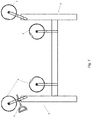
- FIG. 1 shows a 3D labeled exploded drawing of an embodiment of the inventive door leaf handler in open configuration, awaiting placement therein of a door leaf on which hardware is to be installed.
- FIG. 1 shows, inter alia, rotation stops appear on the non-hinged side of each of the half circle arcs of the rotatable frame of the door leaf handler. They are shown as overhangs of the diameter chord of each of the half circle arcs.
- FIG. 2 shows a pin and welded double acting hinge (one of several types of hinge designs that may operate as part of the inventive handler), which allows the door leaf handler (e.g., a clamshell) to be opened from either side of the frame.
- FIGS. 2-7 show individual aspects/portions of the door leaf handler with the proper operating function of each element of the device as may appear in various embodiments of the inventive technology.
- FIG. 3 shows a lift assisting strut (here, 110 lb. hydraulic cylinders) that may be added to each hinge in certain embodiments of the inventive technology to assist in opening and closing the door leaf handler.
- a lift assisting strut here, 110 lb. hydraulic cylinders
- FIG. 4 shows a spring-biased lock that may be used to hold the rotatable frame of the door leaf handler in the working, desired rotational orientation and position, in particular embodiments of the inventive technology.
- FIG. 5A and 5B show a removable, padded door leaf securement rail that, in particular embodiments of the inventive technology, may be placed on the working surfaces of the door leaf handler (e.g., of the two halves of the frame) in order to protect the door leaf while hardware is being installed.
- the padded rails may be replaceable, detachable (e.g., with bolts, clips, Velcro, magnets, etc.), and removable from the door leaf handler and may vary in thickness to adjust for different door thicknesses. In an alternate design (e.g., FIG. 8 ), it may be only pads that are attached (e.g. with bolts, clips, Velcro, magnets, etc.) and removed from the frame (whose rails are not removed to change pads).
- FIG. 6 shows an embodiment of a rotatable frame of a clamshell-type door leaf handler in open configuration to allow for placement of a door leaf in need of hardware installation and removal of a completed, hardwared door leaf.
- hardware may be installed onto the door leaf.
- the rotational frame here, a type of skeletal barrel assembly
- the rotational frame can be rotated to allow access to an opposite side of the door leaf for hardware installation at an opposite of the door leaf if needed.
- FIG. 7 shows an embodiment of a 8-wheel (a broad term that includes any type of wheel (inflatable or not) or roller, including but not limited to tire, plastic disc, etc.) stationary support for rotating clam shell (barrel) type wheel handler so as to keep the working platform stable in the horizontal locked position, and allow for rotation of the secured door leaf when desired (e.g., in order to more easily install certain door hardware).
- clam shell barrel
- the rollers allow for the rotatable frame to remain closed and secured.
- FIG. 8 shows a 3D drawing of an embodiment of the inventive door leaf handler in open configuration, awaiting placement therein of a door leaf on which hardware is to be installed.
- FIG. 9 shows a side view of an embodiment of the inventive door leaf handler in closed position around a door leaf on which hardware is to be installed.
- FIG. 10 shows a 3D drawing of an embodiment of the inventive door leaf handler in closed position around a door on which hardware is to be installed. Rotation of the frame is prevented by locks, which are shown in locked mode.
- the present invention includes a variety of aspects, which may be combined in different ways.
- the following descriptions are provided to list elements and describe some of the embodiments of the present invention. These elements are listed with initial embodiments; however, it should be understood that they may be combined in any manner and in any number to create additional embodiments.
- the variously described examples and preferred embodiments should not be construed to limit the present invention to only the explicitly described systems, techniques, and applications.
- the specific embodiment or embodiments shown are examples only. The specification should be understood and is intended as supporting broad claims as well as each embodiment, and even claims where other embodiments may be excluded.
- rotatable frame 12 rotatable manually and/or via possibly electrical or motorized power assisted method
- That rotatable frame may also: be rotatable about a frame rotation axis, comprise at least one hinge, and door leaf securement rails 11 , and may be configured to be openable and closeable at the at least one hinge 3 along a rotatable frame opening axis.
- Wheels 4 may be configured to allow rotation of said rotatable frame about a frame rotation axis 5 ; accordingly, wheels may be mounted to and form part of the stationary support 6 and/or be mounted to and form part of the rotatable frame 12 .
- the rotatable frame 12 may be in contact with and ride on the wheels.
- the wheels allow the rotatable frame's facile rotation.
- the support 8 e.g. a stationary frame
- outer rims e.g., circular arc portions 9 at opposing ends of the rotatable frame
- the rotatable frame may be shaped to cooperatively interface so that the rotatable frame does not fall off of or out of the supporting wheels.
- wheels move (i.e., rotate), they are considered part of the stationary support where they are mounted to the stationary support, because their axes are stationary in such design.
- Wheels may instead be mounted to the rotatable frame, cooperatively interfacing with a circular arc (with open side facing upwards) that could be established as part of the stationary support.
- At least one of the rotatable frame 12 and the wheels 4 may be shaped so that the rotatable frame and the wheels cooperatively interface so as to keep the rotatable frame on the wheels during rotation of the rotatable frame.
- a circular arc potion 9 has a concave outer shape so that the wheels stay in the circular arc(s) during rotation of the rotatable frame.
- the wheels themselves may have concave outer portions, and the portion of the circular arc portions 9 that contacts them may have a convex, potentially rounded outer shape that securely interfaces with the concave wheels.
- wheel is a broad term and includes but is not limited to wheels with tires (the tire is part of the wheel), rigid material rollers (e.g., plastic rollers, or polyurethane rollers, with or without bearings), etc.
- the wheels may lie in two vertical planes (some, e.g., a first half, in one, and a remainder, e.g., a second half, in the other).
- Two portions (e.g., circular arc portions connected via the connection frame 14 ) of the rotatable frame may also lie in those planes, as may hinges 3 . In embodiments with two locks 15 , such may also lie in such planes (one in each).
- the rotatable frame when closed, in certain embodiments (e.g., particularly where the two (connected) outer portions of the rotatable frame are circular 9 ) may have the shape of a cylinder lying on its side.
- the stationary support is substantially (mostly) above the stationary support, although the inventive technology, as described and claimed, may indeed cover apparatus where significant portions of the stationary support are above or at substantially (within 10% of) the same height as, the rotatable frame.
- Such design may be seen where the stationary support is hanging from an overhead factory support such as a ceiling beam.
- the rotatable frame may include two portions (e.g., circular arc portions 9 ) connected to each other via a connection frame 14 .
- the two portions may be in a first and second vertical plane.
- That connection frame may be configured to allow working access between the two portions from each of two working sides of the door leaf handler. This may be achieved by not placing the any portion of the connection frame 14 between ends of the circular arc portions (e.g., at the ends where hinges may be, or at the opposite end where rotation stops may be) of the rotatable frame, as such could preclude access to the door leaf from a working side of the door leave when the rotatable frame is in a working rotational position.
- the rotatable frame may be openable and closeable at at least one hinge 3 to expose the door leaf securement rails 11 .
- the door leaf 5 can be placed in or removed from the rotatable frame when it is in open mode. Then, once a door leaf is placed in the rotatable frame, the rotatable frame can then be closed onto it and, if it is in (or after being moved to) a working rotational position and if a lock 15 is provided, the frame 12 can be locked in that position (if not already locked).
- one or more lift assisting struts 16 may be provided in order to assist opening and closing (and possibly prevent slamming during closure) of the rotatable frame.
- Embodiments of the inventive technology may include rotational stop(s) 17 that stop rotation of the rotational frame at a first working rotational position (e.g., see FIG. 9 ) from continued rotation in first rotational direction 18 (see FIG. 9 ) and at a second working rotational position ( FIG. 9 but where hinge 3 is at left side of that figure) from continued rotation in a second, opposite rotational direction.
- Lock(s) 15 may be operable to lock the rotatable frame in the first and second working rotational positions. Stops may be extensions of rail beyond the circular arc portion.
- door leaf securement rails 11 may include at least one removable (attachable and detachable) pad 20 . That pad may be removed and replaced with a pad of a different thickness when a door leaf of a different thickness is to be placed in the apparatus in order to assure sufficient pressurized contact between the rotatable frame and the door leaf (both from above and below), so the door leaf is securely “sandwiched” between rails (see, e.g., FIG. 10 ) in certain designs.
- An independent reason for a pad may be simply prevention of marring of the rails that contact the door leaf (whether those rails be those below the door leaf alone, or those plus those above it).
- the pad may attach in a variety of manners (e.g., clip on, it may be shaped to securely rest on the rail, etc.)
- rails themselves may instead be padded, and may be removable and replaceable with a padded rail of a different, appropriate thickness.
- One way such replaceable padded rails may be attached to the rest of the rotatable frame (that they may form a part of) is clips, magnets, elastic bands, etc. (as but a few examples).
- rail is a broad term, and even includes what might conventionally be viewed as a flat surface, plate, or web of rigid material.
- an articulated hinge may be used instead of (or perhaps even in addition to) a replaceable pad or padded rail, in order to assure steady, uniform and sufficient pressurization of the rails against the door leaf.
- An articulated hinge (a type of hinge 3 ) may “automatically” adjust to the width of the door leaf. Any sort of hinge 3 , articulating or not, maybe be double acting in that it allows for hinged opening in two opposite rotational directions. Note that hinges may be said to be substantially in the same vertical plane as the connected portions of the rotatable frame, meaning that a vertical plane containing the center of the hinges coincides with vertical planes bisecting the connected portions (e.g. circular arc portions) of the rotatable frame.
- the apparatus may include at least one lock 15 operable (e.g., manually) to lock the rotatable frame in at least two different working rotational positions.
- the lock(s) may be spring biased, e.g., biased towards a locked position or an unlocked position.
- Lock(s) may be retainable in an unlocked configuration (e.g., where the lock can be disengaged and manually rotated (e.g., by 90° about the translation axis of its pin) to prevent locking engagement), although this is not a required feature.
- Part of the lock may be the hole(s), perhaps on the rotatable frame; a pin (possibly spring biased) of the lock may lock the rotatable frame in a certain rotational position relative to the stationary support when that pin enters such hole.
- Holes may be intentionally positioned so as to enable locking of the rotatable frame in working rotational positions so as to place the door leaf in working door leaf horizontal orientations, each allowing installation of hardware from different sides of the door leaf.
- a hardware installer may pull the lock handle out of its locked position, then rotate the frame such that the end of the lock pin (that terminates in a hole in locked mode) slides against the outer circumference (e.g. circular arc portions) of the rotatable frame during rotation of that frame and “automatically” (due to the bias force) falls into a different lock hole in a different part of the rotatable frame.
- a hardware installer may pull the lock handle out of its locked position, then rotate the frame such that the end of the lock pin (that terminates in a hole in locked mode) slides against the outer circumference (e.g. circular arc portions) of the rotatable frame during rotation of that frame and “automatically” (due to the bias force) falls into a different lock hole in a different part of the rotatable frame.
- lock(s) may require alignment of a lock pin with the hole, manually pushing in the lock, and perhaps turning it (e.g., 90 degrees) so that the bias (e.g., a spring) does not force the lock end out of locking position.
- the bias e.g., a spring
- each of the two locks may operate on a different one of two portions (each portion perhaps being hinged) of the rotatable frame and may be configured for manual operation from a different working side of the door leaf handler.
- hardware may be installed while the operator is standing on any one of two different working sides (after installation on a first side of the door leaf by a hardware installer on one working side, the door leaf may be rotated 180° and hardware on the second side of the door leaf may be installed by the installer at that same working side).
- certain embodiments of the inventive technology disclosed herein offer the installer the option of leaving the door in its orientation, and walking around to the other working side, or instead, the installer could stay in his/her position, unlock the rotatable frame (if locked), and rotate the rotatable frame (with door leave secured therein) 180° about its rotational axis (which may be parallel to the long axis of the door).
- the rotational stops may facilitate the rotation of the rotatable frame (and the door in it) about its axis, providing a secure, defined stop, often at a rotational position at which the lock(s) can secure it.
- Hinges may serve as “backstops” that may prevent the door from sliding when an installer is installing from a working side that is opposite the hinges.
- each hinge 2 there may be a lift assist strut 16 , e.g., a hydraulic cylinder, to assist with the opening and closing of the openable rotatable frame.
- the lift assist struts may be a component of certain embodiments, and may be most susceptible to wearing out and needing replacing, but cylinders are readily available. Certain preferred embodiments are without parts that need repeated maintenance to maintain smooth operation.
- each of the various aspects of the inventive technology may have a specific function that, perhaps used in a particular order, allows for securement of a door leaf for hardware installation.
- the door leaf handler was designed to assist in the preinstallation of door hardware.
- FIG. 1 door not shown
- the 3D drawing shows a stable, horizontal, platform (establishing the lower two of the four rails 11 ) of a door leaf handler with a biased locking system, in the open position, awaiting placement thereon of a door leaf. It shows an open clamshell-type rotatable frame for easy loading and unloading with 110 lb.
- the lock can be released (e.g., if it is desired to flip the orientation of the door in order to facilitate installation of remaining hardware) and the rotatable frame can easily be rotated 180 degrees (stopped by any rotation stops that may exist, e.g., as shown in the figures) and locked to the next (opposite) horizontal working position. Rotational stops as shown may stop rotation when they hit a wheel that facilitates rotation, in certain embodiments.
- An inventive method may relate to the use of the door leaf handler, perhaps as described above, in addition to the use of any sort of door leaf lifter (e.g., a crane-supported and -moved vacuum lifter (that uses suction to attach to the door leaf, thereafter being lifted by the crane and repositioned by the crane, and then releasing such vacuum to release the door into desired position into the open door leaf handler)).
- door leaf lifter e.g., a crane-supported and -moved vacuum lifter (that uses suction to attach to the door leaf, thereafter being lifted by the crane and repositioned by the crane, and then releasing such vacuum to release the door into desired position into the open door leaf handler).
- Such lifter lifts door leaves, typically individually, from a pre-hardware installation orientation (e.g., horizontal, when stored) and places them the same orientation (e.g., horizontal) into an open door leaf handler for hardware installation.
- That same lift may then remove the hardware-installed door from a certain orientation (e.g., horizontal) in the opened (after hardware installation) door leaf handler, and then place it in a post-hardware installation orientation that is perhaps the same as that orientation in which the hardware installed door was removed from the open door leaf handler.
- a certain orientation e.g., horizontal
- post-hardware installation orientation e.g., horizontal
- Time may be saved, and the entire process made more efficient, if there is little or no reorientation of the door during its transit from pre-installation to the door leaf handler and then also during its transit from the door leaf handler to its post hardware installation storage location. Purely translational motion of the door leaf during its pre- and post-installation transit may yield the greatest time savings.
- the entire door hardware installation process may generally be a one-person task, thus eliminating the need of additional staff to turn the door leaf over at any point in the entire process (further, there may be no need to re-orient the door leaf when it is being moved from its storage location, whether manually, or via lift or crane, as relatively simple and fast translational motion of the door leaf may be all that is required).
- the inventive technology has a variety of applications, including but not limited to use in a large assembly process or an individual hardware installation scenario. In either, the cost savings may stem from less man-power, precision installation, faster door leaf transport to and from the hardware installation setting/location, and a less physically taxing working environment.
- any sufficiently rigid/strong material could be used
- wood for a lighter weight device but one that may be easily degradable or damaged aluminum for lighter weight and longer shelf life but susceptibility to easy bending
- certain embodiments may preferably use steel for durability in design and strength to withstand years of use.
- Certain plastics or other non-metal materials could also be used to provide an acceptable strength.
- certain embodiments of the inventive technology have few parts that could wear out and require replacement.
- the basic concepts of the present invention may be embodied in a variety of ways. It involves both door leaf securement techniques as well as devices to accomplish the appropriate securement.
- the securement techniques are disclosed as part of the results shown to be achieved by the various devices described and as steps which are inherent to utilization. They are simply the natural result of utilizing the devices as intended and described.
- some devices are disclosed, it should be understood that these not only accomplish certain methods but also can be varied in a number of ways. Importantly, as to all of the foregoing, all of these facets should be understood to be encompassed by this disclosure.
- each of the various elements of the invention and claims may also be achieved in a variety of manners.
- an element is to be understood as encompassing individual as well as plural structures that may or may not be physically connected.
- This disclosure should be understood to encompass each such variation, be it a variation of an embodiment of any apparatus embodiment, a method or process embodiment, or even merely a variation of any element of these.
- the words for each element may be expressed by equivalent apparatus terms or method terms—even if only the function or result is the same. Such equivalent, broader, or even more generic terms should be considered to be encompassed in the description of each element or action.
- each of the door leaf securement devices as herein disclosed and described, ii) the related methods disclosed and described, iii) similar, equivalent, and even implicit variations of each of these devices and methods, iv) those alternative designs which accomplish each of the functions shown as are disclosed and described, v) those alternative designs and methods which accomplish each of the functions shown as are implicit to accomplish that which is disclosed and described, vi) each feature, component, and step shown as separate and independent inventions, vii) the applications enhanced by the various systems or components disclosed, viii) the resulting products produced by such systems or components, ix) each system, method, and element shown or described as now applied to any specific field or devices mentioned, x) methods and apparatuses substantially as described hereinbefore and with reference to any of the accompanying examples, xi) an apparatus for performing the methods described herein comprising means for performing the steps, xii) the various combinations and permutations of each of the
- any claims set forth at any time are hereby incorporated by reference as part of this description of the invention, and the applicant expressly reserves the right to use all of or a portion of such incorporated content of such claims as additional description to support any of or all of the claims or any element or component thereof, and the applicant further expressly reserves the right to move any portion of or all of the incorporated content of such claims or any element or component thereof from the description into the claims or vice-versa as necessary to define the matter for which protection is sought by this application or by any subsequent continuation, division, or continuation-in-part application thereof, or to obtain any benefit of, reduction in fees pursuant to, or to comply with the patent laws, rules, or regulations of any country or treaty, and such content incorporated by reference shall survive during the entire pendency of this application including any subsequent continuation, division, or continuation-in-part application thereof or any reissue or extension thereon.
Landscapes
- Engineering & Computer Science (AREA)
- Mechanical Engineering (AREA)
- Wing Frames And Configurations (AREA)
Abstract
Description
Claims (16)
Priority Applications (1)
| Application Number | Priority Date | Filing Date | Title |
|---|---|---|---|
| US16/555,807 US11020841B2 (en) | 2018-08-29 | 2019-08-29 | Door leaf handler for installation of door hardware |
Applications Claiming Priority (2)
| Application Number | Priority Date | Filing Date | Title |
|---|---|---|---|
| US201862724494P | 2018-08-29 | 2018-08-29 | |
| US16/555,807 US11020841B2 (en) | 2018-08-29 | 2019-08-29 | Door leaf handler for installation of door hardware |
Publications (2)
| Publication Number | Publication Date |
|---|---|
| US20200070318A1 US20200070318A1 (en) | 2020-03-05 |
| US11020841B2 true US11020841B2 (en) | 2021-06-01 |
Family
ID=69641918
Family Applications (1)
| Application Number | Title | Priority Date | Filing Date |
|---|---|---|---|
| US16/555,807 Active 2040-01-27 US11020841B2 (en) | 2018-08-29 | 2019-08-29 | Door leaf handler for installation of door hardware |
Country Status (1)
| Country | Link |
|---|---|
| US (1) | US11020841B2 (en) |
Families Citing this family (2)
| Publication number | Priority date | Publication date | Assignee | Title |
|---|---|---|---|---|
| US11020841B2 (en) * | 2018-08-29 | 2021-06-01 | Plains Specialty Equipment, Llc | Door leaf handler for installation of door hardware |
| US20250159853A1 (en) * | 2023-11-09 | 2025-05-15 | Group Up Industrial Co., Ltd. | Carrying device for substrate carrier |
Citations (4)
| Publication number | Priority date | Publication date | Assignee | Title |
|---|---|---|---|---|
| US5762348A (en) * | 1996-09-09 | 1998-06-09 | Echternacht Construction Corp. | Carriage for a construction panel |
| US6231034B1 (en) * | 1999-10-27 | 2001-05-15 | Michael R. Walker | Door mounting apparatus |
| US20140084530A1 (en) * | 2012-09-24 | 2014-03-27 | Michelin Recherche Et Technique S.A. | Tire work stand |
| US20200070318A1 (en) * | 2018-08-29 | 2020-03-05 | Plains Specialty Equipment LLC | Door Leaf Handler for Installation of Door Hardware |
-
2019
- 2019-08-29 US US16/555,807 patent/US11020841B2/en active Active
Patent Citations (5)
| Publication number | Priority date | Publication date | Assignee | Title |
|---|---|---|---|---|
| US5762348A (en) * | 1996-09-09 | 1998-06-09 | Echternacht Construction Corp. | Carriage for a construction panel |
| US5762348C1 (en) * | 1996-09-09 | 2001-03-20 | Hardnox Llc | Carriage for a construction panel |
| US6231034B1 (en) * | 1999-10-27 | 2001-05-15 | Michael R. Walker | Door mounting apparatus |
| US20140084530A1 (en) * | 2012-09-24 | 2014-03-27 | Michelin Recherche Et Technique S.A. | Tire work stand |
| US20200070318A1 (en) * | 2018-08-29 | 2020-03-05 | Plains Specialty Equipment LLC | Door Leaf Handler for Installation of Door Hardware |
Also Published As
| Publication number | Publication date |
|---|---|
| US20200070318A1 (en) | 2020-03-05 |
Similar Documents
| Publication | Publication Date | Title |
|---|---|---|
| US11020841B2 (en) | Door leaf handler for installation of door hardware | |
| US5136811A (en) | Torque rod counterbalanced door assembly | |
| US9375369B2 (en) | Vehicle lift with biasing device | |
| CN209507481U (en) | A kind of car body hoistable platform | |
| CN111362128B (en) | House building assembled I-beam lifting device | |
| US20250253628A1 (en) | Cable positioning assembly and pulling system | |
| CN223588583U (en) | Road bridge construction reinforcing bar interfacing apparatus | |
| CN218875240U (en) | Rotatable aircraft refueling nacelle cabin door riveting clamp | |
| CN214422087U (en) | Hoisting device for highway construction | |
| CN222512742U (en) | Guide rail structure for single-beam crane | |
| CN205423459U (en) | Safe operating device of aerial work upset platform | |
| US20250121869A1 (en) | Door supporting apparatus | |
| CN2205281Y (en) | Rapid center frame | |
| CN214615610U (en) | Fixing device is restoreed in ancient building crack | |
| CN223562536U (en) | Steel construction factory building roof girder steel hoist and mount positioner | |
| CN222629351U (en) | Liftable handcart | |
| CN215631438U (en) | Supporting structure for building engineering construction | |
| CN216235532U (en) | Floor landing door structure for construction elevator | |
| CN218055280U (en) | Equipment transportation device for electromechanical engineering | |
| CN220298618U (en) | Externally hung spare tire rack mounting device | |
| CN206529204U (en) | Escalator cabin hinge type cover plate | |
| CN215271010U (en) | Protection type outdoor special road surface is with heavy haul case | |
| CN106829301B (en) | A gas storage cylinder handling mechanism | |
| CN220427384U (en) | Hinge page or leaf seat robot welding frock and people's air defense door | |
| CN220415029U (en) | Combined safety guard rail |
Legal Events
| Date | Code | Title | Description |
|---|---|---|---|
| FEPP | Fee payment procedure |
Free format text: ENTITY STATUS SET TO UNDISCOUNTED (ORIGINAL EVENT CODE: BIG.); ENTITY STATUS OF PATENT OWNER: SMALL ENTITY |
|
| FEPP | Fee payment procedure |
Free format text: ENTITY STATUS SET TO SMALL (ORIGINAL EVENT CODE: SMAL); ENTITY STATUS OF PATENT OWNER: SMALL ENTITY |
|
| AS | Assignment |
Owner name: PLAINS SPECIALTY EQUIPMENT, LLC, COLORADO Free format text: ASSIGNMENT OF ASSIGNORS INTEREST;ASSIGNOR:PARKS, JAMES S.;REEL/FRAME:050589/0819 Effective date: 20190828 |
|
| STPP | Information on status: patent application and granting procedure in general |
Free format text: NOTICE OF ALLOWANCE MAILED -- APPLICATION RECEIVED IN OFFICE OF PUBLICATIONS |
|
| STPP | Information on status: patent application and granting procedure in general |
Free format text: AWAITING TC RESP., ISSUE FEE NOT PAID |
|
| STPP | Information on status: patent application and granting procedure in general |
Free format text: NOTICE OF ALLOWANCE MAILED -- APPLICATION RECEIVED IN OFFICE OF PUBLICATIONS |
|
| STPP | Information on status: patent application and granting procedure in general |
Free format text: NOTICE OF ALLOWANCE MAILED -- APPLICATION RECEIVED IN OFFICE OF PUBLICATIONS |
|
| STPP | Information on status: patent application and granting procedure in general |
Free format text: PUBLICATIONS -- ISSUE FEE PAYMENT RECEIVED |
|
| STPP | Information on status: patent application and granting procedure in general |
Free format text: PUBLICATIONS -- ISSUE FEE PAYMENT VERIFIED |
|
| STCF | Information on status: patent grant |
Free format text: PATENTED CASE |
|
| MAFP | Maintenance fee payment |
Free format text: PAYMENT OF MAINTENANCE FEE, 4TH YR, SMALL ENTITY (ORIGINAL EVENT CODE: M2551); ENTITY STATUS OF PATENT OWNER: SMALL ENTITY Year of fee payment: 4 |