US11016319B2 - Display device mountable to wall surface - Google Patents
Display device mountable to wall surface Download PDFInfo
- Publication number
- US11016319B2 US11016319B2 US16/207,516 US201816207516A US11016319B2 US 11016319 B2 US11016319 B2 US 11016319B2 US 201816207516 A US201816207516 A US 201816207516A US 11016319 B2 US11016319 B2 US 11016319B2
- Authority
- US
- United States
- Prior art keywords
- mounting member
- display device
- display panel
- wall surface
- display
- Prior art date
- Legal status (The legal status is an assumption and is not a legal conclusion. Google has not performed a legal analysis and makes no representation as to the accuracy of the status listed.)
- Active, expires
Links
- 239000011521 glass Substances 0.000 claims description 24
- 230000001681 protective effect Effects 0.000 claims description 24
- 230000002093 peripheral effect Effects 0.000 claims description 12
- 238000010586 diagram Methods 0.000 description 12
- 230000003014 reinforcing effect Effects 0.000 description 11
- 230000004048 modification Effects 0.000 description 5
- 238000012986 modification Methods 0.000 description 5
- 239000000758 substrate Substances 0.000 description 4
- 230000000694 effects Effects 0.000 description 3
- 239000004973 liquid crystal related substance Substances 0.000 description 3
- 230000004075 alteration Effects 0.000 description 1
- 238000004140 cleaning Methods 0.000 description 1
- 238000010276 construction Methods 0.000 description 1
- 238000005516 engineering process Methods 0.000 description 1
- 238000004519 manufacturing process Methods 0.000 description 1
- 239000002184 metal Substances 0.000 description 1
- 238000000034 method Methods 0.000 description 1
- 239000010409 thin film Substances 0.000 description 1
Images


Classifications
-
- G—PHYSICS
- G02—OPTICS
- G02F—OPTICAL DEVICES OR ARRANGEMENTS FOR THE CONTROL OF LIGHT BY MODIFICATION OF THE OPTICAL PROPERTIES OF THE MEDIA OF THE ELEMENTS INVOLVED THEREIN; NON-LINEAR OPTICS; FREQUENCY-CHANGING OF LIGHT; OPTICAL LOGIC ELEMENTS; OPTICAL ANALOGUE/DIGITAL CONVERTERS
- G02F1/00—Devices or arrangements for the control of the intensity, colour, phase, polarisation or direction of light arriving from an independent light source, e.g. switching, gating or modulating; Non-linear optics
- G02F1/01—Devices or arrangements for the control of the intensity, colour, phase, polarisation or direction of light arriving from an independent light source, e.g. switching, gating or modulating; Non-linear optics for the control of the intensity, phase, polarisation or colour
- G02F1/13—Devices or arrangements for the control of the intensity, colour, phase, polarisation or direction of light arriving from an independent light source, e.g. switching, gating or modulating; Non-linear optics for the control of the intensity, phase, polarisation or colour based on liquid crystals, e.g. single liquid crystal display cells
- G02F1/133—Constructional arrangements; Operation of liquid crystal cells; Circuit arrangements
- G02F1/1333—Constructional arrangements; Manufacturing methods
- G02F1/133308—Support structures for LCD panels, e.g. frames or bezels
-
- A—HUMAN NECESSITIES
- A47—FURNITURE; DOMESTIC ARTICLES OR APPLIANCES; COFFEE MILLS; SPICE MILLS; SUCTION CLEANERS IN GENERAL
- A47B—TABLES; DESKS; OFFICE FURNITURE; CABINETS; DRAWERS; GENERAL DETAILS OF FURNITURE
- A47B97/00—Furniture or accessories for furniture, not provided for in other groups of this subclass
- A47B97/001—Wall mounting or suspension arrangements for blackboards or the like
-
- A—HUMAN NECESSITIES
- A47—FURNITURE; DOMESTIC ARTICLES OR APPLIANCES; COFFEE MILLS; SPICE MILLS; SUCTION CLEANERS IN GENERAL
- A47F—SPECIAL FURNITURE, FITTINGS, OR ACCESSORIES FOR SHOPS, STOREHOUSES, BARS, RESTAURANTS OR THE LIKE; PAYING COUNTERS
- A47F5/00—Show stands, hangers, or shelves characterised by their constructional features
- A47F5/08—Show stands, hangers, or shelves characterised by their constructional features secured to the wall, ceiling, or the like; Wall-bracket display devices
-
- F—MECHANICAL ENGINEERING; LIGHTING; HEATING; WEAPONS; BLASTING
- F16—ENGINEERING ELEMENTS AND UNITS; GENERAL MEASURES FOR PRODUCING AND MAINTAINING EFFECTIVE FUNCTIONING OF MACHINES OR INSTALLATIONS; THERMAL INSULATION IN GENERAL
- F16M—FRAMES, CASINGS OR BEDS OF ENGINES, MACHINES OR APPARATUS, NOT SPECIFIC TO ENGINES, MACHINES OR APPARATUS PROVIDED FOR ELSEWHERE; STANDS; SUPPORTS
- F16M13/00—Other supports for positioning apparatus or articles; Means for steadying hand-held apparatus or articles
- F16M13/02—Other supports for positioning apparatus or articles; Means for steadying hand-held apparatus or articles for supporting on, or attaching to, an object, e.g. tree, gate, window-frame, cycle
-
- G—PHYSICS
- G09—EDUCATION; CRYPTOGRAPHY; DISPLAY; ADVERTISING; SEALS
- G09F—DISPLAYING; ADVERTISING; SIGNS; LABELS OR NAME-PLATES; SEALS
- G09F9/00—Indicating arrangements for variable information in which the information is built-up on a support by selection or combination of individual elements
-
- G—PHYSICS
- G02—OPTICS
- G02F—OPTICAL DEVICES OR ARRANGEMENTS FOR THE CONTROL OF LIGHT BY MODIFICATION OF THE OPTICAL PROPERTIES OF THE MEDIA OF THE ELEMENTS INVOLVED THEREIN; NON-LINEAR OPTICS; FREQUENCY-CHANGING OF LIGHT; OPTICAL LOGIC ELEMENTS; OPTICAL ANALOGUE/DIGITAL CONVERTERS
- G02F1/00—Devices or arrangements for the control of the intensity, colour, phase, polarisation or direction of light arriving from an independent light source, e.g. switching, gating or modulating; Non-linear optics
- G02F1/01—Devices or arrangements for the control of the intensity, colour, phase, polarisation or direction of light arriving from an independent light source, e.g. switching, gating or modulating; Non-linear optics for the control of the intensity, phase, polarisation or colour
- G02F1/13—Devices or arrangements for the control of the intensity, colour, phase, polarisation or direction of light arriving from an independent light source, e.g. switching, gating or modulating; Non-linear optics for the control of the intensity, phase, polarisation or colour based on liquid crystals, e.g. single liquid crystal display cells
- G02F1/133—Constructional arrangements; Operation of liquid crystal cells; Circuit arrangements
- G02F1/1333—Constructional arrangements; Manufacturing methods
- G02F1/133308—Support structures for LCD panels, e.g. frames or bezels
- G02F1/133314—Back frames
-
- G—PHYSICS
- G02—OPTICS
- G02F—OPTICAL DEVICES OR ARRANGEMENTS FOR THE CONTROL OF LIGHT BY MODIFICATION OF THE OPTICAL PROPERTIES OF THE MEDIA OF THE ELEMENTS INVOLVED THEREIN; NON-LINEAR OPTICS; FREQUENCY-CHANGING OF LIGHT; OPTICAL LOGIC ELEMENTS; OPTICAL ANALOGUE/DIGITAL CONVERTERS
- G02F1/00—Devices or arrangements for the control of the intensity, colour, phase, polarisation or direction of light arriving from an independent light source, e.g. switching, gating or modulating; Non-linear optics
- G02F1/01—Devices or arrangements for the control of the intensity, colour, phase, polarisation or direction of light arriving from an independent light source, e.g. switching, gating or modulating; Non-linear optics for the control of the intensity, phase, polarisation or colour
- G02F1/13—Devices or arrangements for the control of the intensity, colour, phase, polarisation or direction of light arriving from an independent light source, e.g. switching, gating or modulating; Non-linear optics for the control of the intensity, phase, polarisation or colour based on liquid crystals, e.g. single liquid crystal display cells
- G02F1/133—Constructional arrangements; Operation of liquid crystal cells; Circuit arrangements
- G02F1/1333—Constructional arrangements; Manufacturing methods
- G02F1/133308—Support structures for LCD panels, e.g. frames or bezels
- G02F1/133331—Cover glasses
-
- G—PHYSICS
- G02—OPTICS
- G02F—OPTICAL DEVICES OR ARRANGEMENTS FOR THE CONTROL OF LIGHT BY MODIFICATION OF THE OPTICAL PROPERTIES OF THE MEDIA OF THE ELEMENTS INVOLVED THEREIN; NON-LINEAR OPTICS; FREQUENCY-CHANGING OF LIGHT; OPTICAL LOGIC ELEMENTS; OPTICAL ANALOGUE/DIGITAL CONVERTERS
- G02F2201/00—Constructional arrangements not provided for in groups G02F1/00 - G02F7/00
- G02F2201/46—Fixing elements
Definitions
- the present disclosure relates to a display device that is mountable to a wall surface.
- 2002-318550 discloses a configuration in which a display device is mounted to a wall surface by attaching a reinforcing member to the back face of the display device and then screwing screws shut to the wall surface through mounting holes of the display device and mounting holes of the reinforcing member from the front face of the display device.
- the conventional technology is configured such that a reinforcing member for use in wall surface mounting is attached to a back cover of the display device and the reinforcing member projects in the direction (depth direction) that is behind the display device. For this reason, mounting the display device to a wall surface results in a great thickness extending from the wall surface to the front face of the display device. Further, mounting the display device to a wall surface entails the work of attaching a reinforcing sheet as a separate member to the display device, resulting in poor workability.
- a display device including a display panel that displays an image, a back cover disposed on a back face side of the display panel, and a mounting member for fixing the display device to a wall surface.
- the mounting member is provided in a region extending from a front end of the display panel on a display surface side to a back end of the back cover on the back face side so as to fall within a region of the display device when seen from a side of the display device.
- FIG. 1A is a back view schematically showing a configuration of a display device according to a first embodiment of the present disclosure
- FIG. 1B is a top view schematically showing the configuration of the display device according to the first embodiment of the present disclosure
- FIG. 2A is a diagram showing a state where a mounting member according to the first embodiment of the present disclosure is in a first position
- FIG. 2B is a diagram showing a state where the mounting member according to the first embodiment of the present disclosure is in a second position
- FIG. 3A is a cross-sectional view taken along line IIIA-IIIA of FIG. 2A ;
- FIG. 3B is a cross-sectional view taken along line IIIB-IIIB of FIG. 2B ;
- FIG. 4A is a diagram showing a state where a mounting member according to a second embodiment of the present disclosure is in a first position
- FIG. 4B is a cross-sectional view taken along line IVB-IVB of FIG. 4A ;
- FIG. 4C is a diagram showing a state where the mounting member according to the second embodiment of the present disclosure is in a second position
- FIG. 5A is a cross-sectional view taken along line VA-VA of FIG. 1A ;
- FIG. 5B is a cross-sectional view taken along line VB-VB of FIG. 4C ;
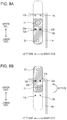
- FIG. 6A is a diagram showing a state where a mounting member according to a third embodiment of the present disclosure is in a first position
- FIG. 6B is a diagram showing a state where the mounting member according to the third embodiment of the present disclosure is in a second position
- FIG. 7A is a diagram showing a state where a mounting member according to a fourth embodiment of the present disclosure is in a second position
- FIG. 7B is a diagram showing a state where the mounting member according to the fourth embodiment of the present disclosure is in the second position
- FIG. 8A is a diagram showing a state where a mounting member of a display device according to a modification is in a first position
- FIG. 8B is a diagram showing a state where the mounting member of the display device according to the modification is in a second position.
- FIG. 1A is a back view schematically showing a configuration of a display device 1 according to a first embodiment of the present disclosure
- FIG. 1B is a top view schematically showing the configuration of the display device 1
- An example of the display device 1 is a display that is used as digital signage outdoors, in a public space in a mean of transportation, or in a similar place. While the display device 1 is used mainly as the digital signage, it may also be used as a normal display indoors.
- a description of components which are identical to those of the first embodiment is omitted by giving them the same signs as those of the first embodiment, and a repeated description of their actions and effects is omitted.
- the display device 1 is mounted, for example, to a wall surface of a facility in a station yard.
- wall surface encompasses not only a column or wall of a facility, an architectural construction, or the like but also a column, a wall, or the like of a moving body such as a means of transportation. The following description is given by taking, as an example, a case where the display device 1 is mounted to a wall surface of a facility.
- the display device 1 schematically includes a display panel unit 2 and mounting members 20 for mounting the display panel unit 2 to a wall surface.
- the display panel unit 2 includes a display panel 3 (e.g. a liquid crystal panel) and a back cover 4 that supports the display panel 3 from a back face side.
- a display panel 3 e.g. a liquid crystal panel
- a back cover 4 that supports the display panel 3 from a back face side.
- the display panel 3 displays, on a display surface 3 a , an image corresponding to an inputted data signal.
- the display panel 3 includes a pair of substrates (thin-film transistor substrate, color filter substrate), a liquid crystal layer disposed between the substrates, a drive circuit, and a backlight.
- the display panel 3 has a conventionally well-known configuration.
- the first embodiment illustrates a liquid crystal panel as an example of the display panel 3
- a display panel according to the present disclosure may foe example be a plasma display, an organic EL display, or a similar display.
- the back cover 4 includes an outer part 4 a placed opposite an outer peripheral side of the display panel 3 and an inner part 4 b , placed opposite a center side of the display panel 3 , that extends (projects) from the outer part 4 a to the back face side.
- the inner part 4 b permits, for example, a bracket conforming to the VESA (Video Electronics Standards Association) (registered trademark) standard to be attached thereto.
- the back cover 4 structurally has a space S 1 , formed around the inner part 4 b , that has a thickness t 4 extending from the outer part 4 a to the inner part 4 b.
- the mounting members 20 are constituted, for example, by sheet metal, and have the strength to be able to support the display device 1 .
- the mounting members 20 are provided on the back face side of the display panel unit 2 . Specifically, the mounting members 20 are provided within the space S 1 of the back cover 4 . Further, as shown in FIG. 1A , the mounting members 20 are provided so as not to project outward from an outer peripheral end of the display panel 3 , i.e. so as to be accommodatable within a region of the display panel 3 , in a plan view of the display panel 3 . Further, the mounting members 20 are attached to the outer part 4 a of the back cover 4 so as to be rotatable with screws 11 as fulcrums. The mounting members 20 will be described in detail later.
- the display device 1 has its front end serving as the display surface 3 a of the display panel 3 on a display surface side and its back end serving as the inner part 4 b of the back cover 4 on the back face side.
- t 1 denotes a thickness extending from the display surface 3 a (front end) to the inner part 4 b (back end). That is, t 1 is the outer thickness of the display device 1 in the depth direction.
- the mounting members 20 are provided at least in a region (within the thickness t 1 ) extending from the front end to the back end. Further, the mounting members 20 fall within a region of the display device 1 as seen from the side of the display device 1 .
- FIGS. 2A and 2B are enlarged views of a mounting member 20 in a part (part A) of the display device 1 shown in FIG. 1A .
- FIG. 2A shows a state where the mounting member 20 is in a position (hereinafter referred to as “first position”) prior to shipment of the display device 1 , prior to mounting of the display device 1 to a wall surface, or during normal use.
- FIG. 3A is a cross-sectional view taken along line of FIG. 2A .
- FIG. 2B shows a state where the mounting member 20 is in a position (hereinafter referred to as “second position”) during the work of mounting the display device 1 to a wall surface.
- FIG. 3B is a cross-sectional view taken along line IIIB-IIIB of FIG. 2B .
- a front frame 5 is provided at the outer peripheral end of the display panel 3 .
- a reinforcing sheet 6 is provided between the display panel 3 and the back cover 4 so as to extend in a vertical direction (see FIG. 1A ). Specifically, the reinforcing sheet 6 is attached to the back face of the display panel 3 in order to secure the strength of the display panel 3 .
- the mounting member 20 includes a screw hole 21 (see FIGS. 3A and 3B ), a screw hole 23 (first screw hole) (see FIGS. 2A and 2B and FIGS. 3A and 3B ), and stopper holes 22 a and 22 b (see FIGS. 2A and 2B ).
- the outer part 4 a of the back cover 4 is provided with protrusions 12 a , 12 b , 13 a , and 13 b .
- the mounting member 20 is fixed to the outer part 4 a of the back cover 4 by a screw 11 being screwed shut to the reinforcing sheet 6 through the screw hole 21 .
- the screw 11 is constituted by a shoulder screw, and the mounting member 20 is rendered rotatable by a space that is formed by a shank of the screw 11 having a predetermined length.
- the mounting member 20 in a case where the mounting member 20 is in the first position, the mounting member 20 is fixed to the outer part 4 a of the back cover 4 by the protrusions 13 a and 13 b being fitted into the stopper holes 22 a and 22 b , respectively. At this point in time, the mounting member 20 is fixed so as to extend in a vertical direction and, when seen in a plan view, falls within the region of the display panel 3 . Further, as shown in FIG. 3 A, a thickness (distance) t 0 extending from the outer part 4 a of the back cover 4 to an end of the mounting member 20 is smaller than a thickness (distance) t 4 extending from the outer part 4 a to the inner part 4 b . Since the mounting member 20 is attached so as to be in contact with the outer part 4 a , the thickness t 0 is substantially equal to the sheet thickness of the mounting member 20 .
- FIG. 2B in a case where the mounting member 20 is in the second position, the mounting member 20 is fixed to the outer part 4 a of the back cover 4 by the protrusions 12 a and 12 b being fitted into the stopper holes 22 a and 22 b , respectively.
- FIG. 3B shows how the protrusion 12 a is fitted in the stopper hole 22 a .
- the mounting member 20 in a case where the mounting member 20 is in the second position, the mounting member 20 is fixed so as to extend in a horizontal direction, and a part of the mounting member 20 projects outward from the outer peripheral end (in FIG. 2B , right end) of the display panel 3 .
- the screw hole 23 of the mounting member 20 stands out of the outer peripheral end of the display panel 3 .
- the outer dimensions of the screw hole 21 (see FIGS. 3A and 3B ) of the mounting member 20 , the screw hole 23 , and the mounting member 20 are set so that the mounting member 20 entirely falls within the region of the display panel 3 when the mounting member 20 is in the first position and the screw hole 23 of the mounting member 20 stands out of the outer peripheral end of the display panel 3 when the mounting member 20 is in the second position.
- the work of moving (work of rotating) the mounting member 20 from the first position (see FIG. 2A ) into the second position (see FIG. 2B ) and the work of moving (work of rotating) the mounting member 20 from the second position into the first position are for example manually performed by a worker.
- a worker moves the mounting member 20 of the display device 1 from the first position into the second position upon delivery by rotating the mounting member 20 in the direction of arrows shown in FIGS. 2B and 3B .
- the worker performs the work on all (in this example, four) mounting members 20 .
- the worker screws a fixing screw 110 (first screw) shut to a wall surface 100 through the screw hole 23 of each of the mounting members 20 as shown in FIG. 3B .
- the mounting member 20 is disposed in a region between the front end (display surface 3 a ) of the display panel 3 on the display surface side and the back end (inner part 4 b of the back cover 4 ) of the display panel 3 on the back face side, or more specifically, a region (the space S 1 of FIGS. 1A and 3A ) between the outer and inner parts 4 a and 4 b of the back cover 4 .
- the outer thickness (t 1 shown in FIGS. 1B and 3A ) of the display device 1 in a case where the display device 1 is mounted to a wall surface can be made equal to the outer thickness of the display device 1 during normal use. Accordingly, the display device 1 according to the first embodiment only needs a smaller mounting space (amount of projection from a wall surface) than a conventional wall-mounted display device.
- the display device 1 makes it unnecessary for a worker to attach a separate member (such as a reinforcing member) to the display device 1 in a work area where the worker mounts the display device 1 to a wall surface, making it only necessary to perform the simple work of rotating the mounting member 20 , with which the display device 1 is already provided. This brings about improvement in workability as compared with a conventional wall-mounted display device.
- a separate member such as a reinforcing member
- the display device 1 allows the mounting member 20 to be fixed so as to, when seen in a plan view, project outward from the display panel 3 only when mounted to a wall surface and fall within the region of the display panel 3 during normal use. This prevents the display device 1 from being defiled during normal use. This also makes it unnecessary to manufacture the display device 1 in different structures depending on applications such as normal use and wall-mounted use, making it possible to achieve commonality of structure of the display device 1 .
- FIGS. 4A to 4C are enlarged views of a mounting member 20 of a display device 1 according to a second embodiment.
- FIGS. 4A to 4C show a part corresponding to part A of FIG. 1A .
- FIG. 4A shows a state where the mounting member 20 is in a first position
- FIG. 4B is a cross-sectional view taken along line IVB-IVB of FIG. 4A
- FIG. 5A is a cross-sectional view taken along line VA-VA of FIG. 4A .
- FIG. 4C shows a state where the mounting member 20 is in a second position
- FIG. 5B is a cross-sectional view taken along line VB-VB of FIG. 4C .
- the outer part 4 a of the back cover 4 has a slit 13 extending in a horizontal direction and stopper holes 14 and 15 provided at both ends, respectively, of the slit 13 .
- the outer part 4 a has a receptor 4 c formed on the display surface side thereof.
- the mounting member 20 is disposed to be received by the receptor 4 c .
- a gripper 25 is screwed shut to the mounting member 20 through the slit 13 from the back face side of the outer part 4 a . This allows, for example, a worker to, as shown in FIGS. 4A and 4C , hold the gripper 25 to move the mounting member 20 in a horizontal direction between the stopper holes 14 and 15 .
- the mounting member 20 is movably (slidably) attached to the outer part 4 a.
- the mounting member 20 is disposed in a region between the display panel 3 and the outer part 4 a of the back cover 4 .
- a thickness t 3 of the region may be increased by reducing the thickness t 4 extending from the outer part 4 a to the inner part 4 b .
- the outer thickness t 1 of the display device 1 in the depth direction be set to be substantially equal no the thickness of an ordinary display device that is not of a wall-mounted type.
- the mounting member 20 in a case where the mounting member 20 is in the first position, the mounting member 20 falls within the region of the display panel 3 when seen in a plan view.
- a part of the mounting member 20 in a case where the mounting member 20 is in the second position, a part of the mounting member 20 , or specifically, a part of the mounting member 20 including the screw hole 23 , projects outward from the outer peripheral end (right end) of the display panel 3 when seen in a plan view.
- the work of moving (work of sliding) the mourn ting member 20 from the first position (see FIG. 4A ) into the second position (see FIG. 4C ) and the work of moving (work of sliding) the mounting member 20 from the second position into the first position are for example manually performed by a worker.
- the worker moves the mounting member 20 of the display device 1 from the first position into the second position upon delivery by sliding the mounting member 20 in the direction of arrows shown in FIGS. 4C and 5B .
- the worker performs the work on all (in this example, four) mounting members 20 .
- the mounting member 20 is disposed in a region between the front end (display surface 3 a ) of the display panel 3 on the display surface side and the back end (inner part 4 b of the back cover 4 ) of the display panel 3 on the back face side, or more specifically, a region (a space S 2 of FIG. 5A ) between the display panel 3 and the outer part 4 a of the back cover 4 .
- the back cover 4 may be configured such that a thickness extending from the display surface 3 a (front end) to the outer part 4 a is equal to the thickness t 1 extending from the display surface 3 a (front end) to the inner part 4 b . That is, the back cover 4 may be configured such that t 4 , shown in FIG. 5A , is set at 0 so that there is no step (projection).
- the display device 1 according to the second embodiment is preferably configured such that the mounting members 20 are attached to the back cover 4 in a case where the display device 1 has a light weight and the mounting members 20 are attached to the reinforcing sheet 6 in a case where the display device 1 has a heavy weight.
- FIGS. 6A and 6B are cross-sectional views showing a configuration of a part of a display device 1 according to a third embodiment.
- FIGS. 6A and 6B show a part corresponding to part A of FIG. 1A . Further, FIG. 6A shows a state where a mounting member 20 is in a first position, and FIG. 6B shows a state where the mounting member 20 is in a second position.
- a mounting member 20 according to the first embodiment has a flat shape
- a mounting member 20 according to the present disclosure is not limited to this shape.
- a mounting member 20 according to the third embodiment in in the shape of letter Z having a step.
- a thickness t 5 extending from an upper end to a lower end of the mounting member 20 is equal to or smaller than the thickness t 4 extending from the outer part 4 a to the inner part 4 b of the back cover 4 (t 5 ⁇ t 4 ).
- the mounting member 20 is disposed in a region between the front end (display surface 3 a ) of the display panel 3 on the display surface side and the back end (inner part 4 b of the back cover 4 ) of the display panel 3 on the back face side, or more specifically, a region (the space S 1 of FIGS. 1A and 6A ) between the outer and inner parts 4 a and 4 b of the back cover 4 .
- This makes it possible to bring about an effect which is similar to that which is brought about by the display device 1 according to the first embodiment.
- the display device 1 according to the third embodiment makes it unnecessary to adjust the space between the wall surface 100 and the mounting member 20 , as the mounting member 20 can be fixed substantially in contact with the wall surface 100 .
- the shape and outer dimensions of the mounting member 20 are not particularly limited and need only be set, for example, according to the magnitude of the thickness t 4 or the size and shape of the fixing screw 110 .
- FIGS. 7A and 7B are cross-sectional views showing a configuration of a part of a display device 1 according to a fourth embodiment.
- FIGS. 7A and 7B show a part corresponding to part A of FIG. 1A . Further, both FIGS. 7A and 7B show a state where a mounting member 20 is in a second position.
- the display device 1 according to the fourth embodiment is configured such that the display device 1 according to the first embodiment further includes a protective glass 7 disposed in front of the display panel 3 .
- the protective glass 7 is provided mainly for the purpose of protecting the display surface 3 a of the display panel 3 .
- the protective glass 7 is larger in outer dimension than the display panel 3 when seen in a plan view, with a cushion rubber 8 disposed between the protective glass 7 and the display panel 3 .
- the protective glass 7 has screw holes 7 a , provided in four corners thereof, through which fixing screws 120 are driven.
- the protective glass 7 is fixed, for example, by the configuration shown in FIG. 7A or the configuration shown in FIG. 7B .
- the mounting member 20 further includes a threaded (tapped) screw hole 24 (screw shutter).
- the protective glass 7 is fixed to the mounting member 20 by a fixing screw 120 (second screw) being screwed shut to the screw hole 24 through a screw hole 7 a (second screw hole).
- This configuration makes it possible to attach the protective glass 7 to the mounting member 20 after having mounted the display device 1 to the wall surface 100 , for example, in accordance with the work procedure shown in the first embodiment. That is, the work of mounting the display device 1 and the work of attaching the protective glass 7 can be separately performed. This makes it possible to improve the workability of the work of replacing the protective glass 7 , the work of cleaning the protective glass 7 , or similar work, as the protective glass 7 can be removed with the display panel 3 kept mounted to the wall surface 100 .
- the mounting member 20 may be configured such that the display panel 3 and the protective glass 7 are simultaneously fixed to the wall surface 100 by a shoulder screw 130 being screwed shut to the wall surface 100 through the screw hole 7 a of the protective glass 7 and the screw hole 23 of the mounting member 20 .
- This configuration makes it possible to omit the screw hole 24 for use in mounting of the protective glass 7 .
- the outer dimensions of the display device 1 including the protective glass 7 can be made smaller, footprint requirements can be reduced.
- the mounting member 20 does not include a screw hole 24 for use in mounting of the protective glass 7 (see FIGS. 2A and 2B , FIGS. 4A to 4C , and FIGS. 6A and 6B ), the mounting member 20 may include a screw hole 24 . This makes it possible to achieve commonalty of parts (mounting members 20 ) regardless of whether the protective glass 7 is used or is not used.
- FIG. 8A is a diagram showing a state where a mounting member 20 of a display device 1 according to a modification is in a first position
- FIG. 8B is a diagram showing a state where the mounting member 20 of the display device 1 according to the modification is in a second position.
- the mounting member 20 may be configured to project toward a higher position than the display panel 3 . This configuration makes it possible to mount the display device 1 to the wall surface in such a way that the display device 1 hangs on the mounting member 20 .
- the display device 1 may be configured such that toe mounting member 20 is immovably fixed to the back cover 4 .
- the mounting member 20 is fixed to the back cover 4 with the screw hole 23 (see, for example, FIGS. 2B and 4C ) standing out of the outer peripheral end of the display panel 3 .
- the configuration eliminates the need for the work of moving the mounting member 20 , and is therefore suitable to a wall-mounted display device that is not normally used.
Landscapes
- Physics & Mathematics (AREA)
- Nonlinear Science (AREA)
- General Physics & Mathematics (AREA)
- Engineering & Computer Science (AREA)
- Optics & Photonics (AREA)
- Crystallography & Structural Chemistry (AREA)
- Chemical & Material Sciences (AREA)
- Mathematical Physics (AREA)
- General Engineering & Computer Science (AREA)
- Mechanical Engineering (AREA)
- Theoretical Computer Science (AREA)
- Devices For Indicating Variable Information By Combining Individual Elements (AREA)
- Liquid Crystal (AREA)
- Casings For Electric Apparatus (AREA)
Abstract
Description
Claims (6)
Applications Claiming Priority (3)
| Application Number | Priority Date | Filing Date | Title |
|---|---|---|---|
| JP2017241126A JP7014587B2 (en) | 2017-12-15 | 2017-12-15 | Display device |
| JP2017-241126 | 2017-12-15 | ||
| JPJP2017-241126 | 2017-12-15 |
Publications (2)
| Publication Number | Publication Date |
|---|---|
| US20190187509A1 US20190187509A1 (en) | 2019-06-20 |
| US11016319B2 true US11016319B2 (en) | 2021-05-25 |
Family
ID=66815082
Family Applications (1)
| Application Number | Title | Priority Date | Filing Date |
|---|---|---|---|
| US16/207,516 Active 2038-12-30 US11016319B2 (en) | 2017-12-15 | 2018-12-03 | Display device mountable to wall surface |
Country Status (3)
| Country | Link |
|---|---|
| US (1) | US11016319B2 (en) |
| JP (1) | JP7014587B2 (en) |
| CN (1) | CN109979315B (en) |
Cited By (2)
| Publication number | Priority date | Publication date | Assignee | Title |
|---|---|---|---|---|
| US11253064B2 (en) * | 2013-06-07 | 2022-02-22 | Legrand Av Inc. | Wall mount system |
| US11310927B2 (en) * | 2018-11-23 | 2022-04-19 | Shenzhen Gloshine Technology Co., Ltd. | LED display screen |
Families Citing this family (1)
| Publication number | Priority date | Publication date | Assignee | Title |
|---|---|---|---|---|
| CN210670872U (en) | 2019-07-18 | 2020-06-02 | 北京小米移动软件有限公司 | Display device rear shell and display device |
Citations (25)
| Publication number | Priority date | Publication date | Assignee | Title |
|---|---|---|---|---|
| US6020867A (en) * | 1995-03-22 | 2000-02-01 | Canon Kabushiki Kaisha | Display apparatus |
| US20020153836A1 (en) | 2001-04-23 | 2002-10-24 | Pioneer Corporation & Shizuoka Pioneer Corporation | Display apparatus |
| US20030217495A1 (en) * | 2002-05-24 | 2003-11-27 | Toshiba Transport Engineering Inc. | Unit connecting mechanism and image display device |
| US20050127260A1 (en) * | 2003-07-11 | 2005-06-16 | Jay Dittmer | Display mounting device |
| US20060060732A1 (en) * | 2004-02-02 | 2006-03-23 | Tannas Lawrence E Jr | Apparatus and methods for mounting flat panel displays |
| US20060087804A1 (en) * | 2003-06-13 | 2006-04-27 | Takayoshi Tsukamoto | Flat display device |
| US7117621B2 (en) * | 1994-07-01 | 2006-10-10 | Cherng Chang | Three dimensional framed display and frame calendar |
| US20100026913A1 (en) * | 2008-07-30 | 2010-02-04 | Hannspree, Inc., | Digital photo frame with interchangeable front frame |
| US7766296B2 (en) * | 2004-07-21 | 2010-08-03 | Lg Electronics Inc. | Wall mounting structure for a flat panel display |
| US20110058112A1 (en) * | 2009-09-10 | 2011-03-10 | Sony Corporation | Digital picture display device |
| US20110198460A1 (en) * | 2010-02-12 | 2011-08-18 | Peerless Industries, Inc. | Adjustable display mount |
| US8008570B2 (en) * | 2008-03-19 | 2011-08-30 | Samsung Electronics Co., Ltd. | Display assembly and display device having the same |
| US20140265775A1 (en) * | 2013-03-15 | 2014-09-18 | Lilitab LLC | Wall Mount With Configurable Stops |
| CN204181334U (en) | 2014-10-29 | 2015-03-04 | 成都雅致工艺品有限公司 | The Domestic distributing box formula picture frame that horizontally slips |
| US20150192956A1 (en) * | 2012-06-11 | 2015-07-09 | Connected Fleet Systems Incorporated | Planar electronic display mount with adjustable keyboard tray |
| US20150226996A1 (en) * | 2012-08-31 | 2015-08-13 | Sharp Kabushiki Kaisha | Display apparatus and television receiver |
| US9374927B2 (en) * | 2013-01-17 | 2016-06-21 | Lg Electronics Inc. | Display device |
| US20160296018A1 (en) * | 2015-04-08 | 2016-10-13 | Samsung Electronics Co., Ltd. | Display apparatus and wall mounting device for display apparatus |
| US20170105293A1 (en) * | 2015-10-08 | 2017-04-13 | Abletech Co., Ltd. | Display device |
| US20170099948A1 (en) * | 2015-10-09 | 2017-04-13 | Panasonic Avionics Corporation | Entertainment display mount |
| CN206460743U (en) | 2016-09-08 | 2017-09-01 | 深圳市合利来科技有限公司 | A kind of LED display maintained easily |
| CN206532529U (en) | 2017-02-28 | 2017-09-29 | 广州市晨显科技有限公司 | A kind of new outdoor advertising mosaic screen |
| US20180325288A1 (en) * | 2015-11-09 | 2018-11-15 | Absolut Art Ab | Mounting device |
| US20190159349A1 (en) * | 2017-07-17 | 2019-05-23 | Unilumin Group Co., Ltd. | Led display |
| US20190212606A1 (en) * | 2016-09-23 | 2019-07-11 | Denso Corporation | Display apparatus |
Family Cites Families (22)
| Publication number | Priority date | Publication date | Assignee | Title |
|---|---|---|---|---|
| JP2000019981A (en) * | 1998-06-30 | 2000-01-21 | Hitachi Ltd | Display device |
| US6477039B2 (en) * | 1999-02-24 | 2002-11-05 | Canon Kabushiki Kaisha | Image display device |
| KR100558949B1 (en) * | 1999-05-03 | 2006-03-10 | 삼성전자주식회사 | Handle fixing structure of LCD monitor |
| TW478700U (en) * | 2000-09-20 | 2002-03-01 | Benq Corp | Wall-hanging type stand for plasma TV |
| CN2693114Y (en) * | 2004-03-23 | 2005-04-20 | 王戈林 | Adjustable hook of picture frame |
| JP2006050203A (en) * | 2004-08-04 | 2006-02-16 | Rb Controls Co | Tv image display device, and half mirror board therefor |
| CN2906837Y (en) * | 2006-04-29 | 2007-05-30 | 茂新五金制品(深圳)有限公司 | Wall-mounted large screen display fixing frame |
| CN200941313Y (en) * | 2006-08-25 | 2007-08-29 | 佛山市顺德区顺达电脑厂有限公司 | Wall frame structure of displayer |
| CN201273970Y (en) * | 2008-09-01 | 2009-07-15 | 成都泉涌科技有限公司 | Anti-scratch LCD |
| US8376308B2 (en) * | 2008-10-17 | 2013-02-19 | Dean Norton Greve′ | Adjustable picture hanger |
| JP5532333B2 (en) * | 2010-10-21 | 2014-06-25 | 株式会社パトライト | Equipment that can be mounted on the wall |
| CN102095053B (en) * | 2011-01-30 | 2013-05-08 | 中国北方车辆研究所 | Method for mounting display |
| CN103730064A (en) * | 2011-06-09 | 2014-04-16 | 明基电通有限公司 | Display device |
| CN202176890U (en) * | 2011-06-17 | 2012-03-28 | 惠州市升华工业有限公司 | Flat-panel television hanger |
| JP5743243B2 (en) * | 2011-07-08 | 2015-07-01 | Necディスプレイソリューションズ株式会社 | Attachment mechanism and attachment method of image display device |
| CN202302620U (en) * | 2011-09-06 | 2012-07-04 | 徐云 | Novel ultrathin television bracket |
| JP2013092558A (en) * | 2011-10-24 | 2013-05-16 | Panasonic Corp | Image display apparatus |
| JP2014066833A (en) * | 2012-09-25 | 2014-04-17 | Sharp Corp | Display unit capable of being hung on wall and television including the same |
| JP2014174481A (en) * | 2013-03-12 | 2014-09-22 | Sharp Corp | Image display device |
| JP6189681B2 (en) * | 2013-08-27 | 2017-08-30 | シャープ株式会社 | Display device and mounting structure |
| JP2016009073A (en) * | 2014-06-24 | 2016-01-18 | シャープ株式会社 | Display device and manufacturing method of display device |
| CN104315317B (en) * | 2014-10-20 | 2016-09-07 | 苏州佳世达电通有限公司 | Display hanging structure |
-
2017
- 2017-12-15 JP JP2017241126A patent/JP7014587B2/en active Active
-
2018
- 2018-12-03 US US16/207,516 patent/US11016319B2/en active Active
- 2018-12-15 CN CN201811537791.6A patent/CN109979315B/en active Active
Patent Citations (29)
| Publication number | Priority date | Publication date | Assignee | Title |
|---|---|---|---|---|
| US7117621B2 (en) * | 1994-07-01 | 2006-10-10 | Cherng Chang | Three dimensional framed display and frame calendar |
| US6020867A (en) * | 1995-03-22 | 2000-02-01 | Canon Kabushiki Kaisha | Display apparatus |
| US20020153836A1 (en) | 2001-04-23 | 2002-10-24 | Pioneer Corporation & Shizuoka Pioneer Corporation | Display apparatus |
| JP2002318550A (en) | 2001-04-23 | 2002-10-31 | Pioneer Electronic Corp | Display device |
| US6688576B2 (en) | 2001-04-23 | 2004-02-10 | Pioneer Corporation | Display apparatus |
| US20030217495A1 (en) * | 2002-05-24 | 2003-11-27 | Toshiba Transport Engineering Inc. | Unit connecting mechanism and image display device |
| US20060087804A1 (en) * | 2003-06-13 | 2006-04-27 | Takayoshi Tsukamoto | Flat display device |
| US20050127260A1 (en) * | 2003-07-11 | 2005-06-16 | Jay Dittmer | Display mounting device |
| US20060060732A1 (en) * | 2004-02-02 | 2006-03-23 | Tannas Lawrence E Jr | Apparatus and methods for mounting flat panel displays |
| US7766296B2 (en) * | 2004-07-21 | 2010-08-03 | Lg Electronics Inc. | Wall mounting structure for a flat panel display |
| US8008570B2 (en) * | 2008-03-19 | 2011-08-30 | Samsung Electronics Co., Ltd. | Display assembly and display device having the same |
| US20100026913A1 (en) * | 2008-07-30 | 2010-02-04 | Hannspree, Inc., | Digital photo frame with interchangeable front frame |
| US20110058112A1 (en) * | 2009-09-10 | 2011-03-10 | Sony Corporation | Digital picture display device |
| US20110198460A1 (en) * | 2010-02-12 | 2011-08-18 | Peerless Industries, Inc. | Adjustable display mount |
| CA2788427A1 (en) * | 2010-02-12 | 2011-08-18 | Peerless Industries, Inc. | Adjustable display mount |
| US20150192956A1 (en) * | 2012-06-11 | 2015-07-09 | Connected Fleet Systems Incorporated | Planar electronic display mount with adjustable keyboard tray |
| US20150226996A1 (en) * | 2012-08-31 | 2015-08-13 | Sharp Kabushiki Kaisha | Display apparatus and television receiver |
| US9374927B2 (en) * | 2013-01-17 | 2016-06-21 | Lg Electronics Inc. | Display device |
| US20140265775A1 (en) * | 2013-03-15 | 2014-09-18 | Lilitab LLC | Wall Mount With Configurable Stops |
| US9416912B2 (en) * | 2013-03-15 | 2016-08-16 | Lilitab LLC | Wall mount with configurable stops |
| CN204181334U (en) | 2014-10-29 | 2015-03-04 | 成都雅致工艺品有限公司 | The Domestic distributing box formula picture frame that horizontally slips |
| US20160296018A1 (en) * | 2015-04-08 | 2016-10-13 | Samsung Electronics Co., Ltd. | Display apparatus and wall mounting device for display apparatus |
| US20170105293A1 (en) * | 2015-10-08 | 2017-04-13 | Abletech Co., Ltd. | Display device |
| US20170099948A1 (en) * | 2015-10-09 | 2017-04-13 | Panasonic Avionics Corporation | Entertainment display mount |
| US20180325288A1 (en) * | 2015-11-09 | 2018-11-15 | Absolut Art Ab | Mounting device |
| CN206460743U (en) | 2016-09-08 | 2017-09-01 | 深圳市合利来科技有限公司 | A kind of LED display maintained easily |
| US20190212606A1 (en) * | 2016-09-23 | 2019-07-11 | Denso Corporation | Display apparatus |
| CN206532529U (en) | 2017-02-28 | 2017-09-29 | 广州市晨显科技有限公司 | A kind of new outdoor advertising mosaic screen |
| US20190159349A1 (en) * | 2017-07-17 | 2019-05-23 | Unilumin Group Co., Ltd. | Led display |
Cited By (4)
| Publication number | Priority date | Publication date | Assignee | Title |
|---|---|---|---|---|
| US11253064B2 (en) * | 2013-06-07 | 2022-02-22 | Legrand Av Inc. | Wall mount system |
| US20220142368A1 (en) * | 2013-06-07 | 2022-05-12 | Legrand Av Inc. | Wall mount system |
| US11602217B2 (en) * | 2013-06-07 | 2023-03-14 | Legrand Av Inc. | Wall mount system |
| US11310927B2 (en) * | 2018-11-23 | 2022-04-19 | Shenzhen Gloshine Technology Co., Ltd. | LED display screen |
Also Published As
| Publication number | Publication date |
|---|---|
| JP7014587B2 (en) | 2022-02-01 |
| CN109979315B (en) | 2021-11-30 |
| US20190187509A1 (en) | 2019-06-20 |
| JP2019109312A (en) | 2019-07-04 |
| CN109979315A (en) | 2019-07-05 |
Similar Documents
| Publication | Publication Date | Title |
|---|---|---|
| US11016319B2 (en) | Display device mountable to wall surface | |
| US20140166834A1 (en) | Bracket, attaching system, paper pattern, display apparatus, and television receiver | |
| TW200951482A (en) | Laser pointer visibility improving film, polarizing plate, image display, and laser pointer display method | |
| US20160274296A1 (en) | Backlight Module and Display Device | |
| US20140063403A1 (en) | Display module and display device | |
| US8960982B2 (en) | Electronic apparatus having a display unit | |
| US20170176805A1 (en) | Display module and display device comprising display module | |
| CN103823321A (en) | Curved surface liquid crystal display device | |
| US10466520B2 (en) | Direct-bonding liquid crystal display module and assembly process thereof | |
| CN104641280A (en) | Computer backlight unit (BLU) attachment to cover glass/cell | |
| CN108172124A (en) | Flexible display device | |
| US9958715B2 (en) | Display device framework and display device | |
| US20170131580A1 (en) | Rubber frame component, backlight module and display device | |
| CN106094310A (en) | The method attaching polaroid on LCD base board | |
| US9360194B2 (en) | Frame of backlight module, a backlight module and a display device | |
| WO2016127621A1 (en) | Display module and display device | |
| US10203445B2 (en) | Backlight unit, display panel and display device | |
| US20150268507A1 (en) | Curved liquid crystal display device | |
| CN209960163U (en) | Adjusting bracket of display screen | |
| KR101419347B1 (en) | Apparatus for laminating | |
| KR20130107885A (en) | Display apparatus | |
| CN105116561A (en) | Anti-peep display system and 3D glasses thereof | |
| US9651809B2 (en) | Display module and display device | |
| US20150261034A1 (en) | Display apparatus | |
| US20140092539A1 (en) | Electronic apparatus |
Legal Events
| Date | Code | Title | Description |
|---|---|---|---|
| AS | Assignment |
Owner name: SHARP KABUSHIKI KAISHA, JAPAN Free format text: ASSIGNMENT OF ASSIGNORS INTEREST;ASSIGNORS:IEMURA, HIROTOSHI;ABE, OSAMU;REEL/FRAME:047657/0803 Effective date: 20181112 |
|
| FEPP | Fee payment procedure |
Free format text: ENTITY STATUS SET TO UNDISCOUNTED (ORIGINAL EVENT CODE: BIG.); ENTITY STATUS OF PATENT OWNER: LARGE ENTITY |
|
| STPP | Information on status: patent application and granting procedure in general |
Free format text: DOCKETED NEW CASE - READY FOR EXAMINATION |
|
| STPP | Information on status: patent application and granting procedure in general |
Free format text: NON FINAL ACTION MAILED |
|
| STPP | Information on status: patent application and granting procedure in general |
Free format text: RESPONSE TO NON-FINAL OFFICE ACTION ENTERED AND FORWARDED TO EXAMINER |
|
| STPP | Information on status: patent application and granting procedure in general |
Free format text: NON FINAL ACTION MAILED |
|
| STPP | Information on status: patent application and granting procedure in general |
Free format text: DOCKETED NEW CASE - READY FOR EXAMINATION |
|
| STPP | Information on status: patent application and granting procedure in general |
Free format text: NOTICE OF ALLOWANCE MAILED -- APPLICATION RECEIVED IN OFFICE OF PUBLICATIONS |
|
| STPP | Information on status: patent application and granting procedure in general |
Free format text: PUBLICATIONS -- ISSUE FEE PAYMENT RECEIVED |
|
| STPP | Information on status: patent application and granting procedure in general |
Free format text: PUBLICATIONS -- ISSUE FEE PAYMENT VERIFIED |
|
| STCF | Information on status: patent grant |
Free format text: PATENTED CASE |
|
| MAFP | Maintenance fee payment |
Free format text: PAYMENT OF MAINTENANCE FEE, 4TH YEAR, LARGE ENTITY (ORIGINAL EVENT CODE: M1551); ENTITY STATUS OF PATENT OWNER: LARGE ENTITY Year of fee payment: 4 |