US10999915B2 - Lighting control device and lighting apparatus including same - Google Patents
Lighting control device and lighting apparatus including same Download PDFInfo
- Publication number
- US10999915B2 US10999915B2 US16/462,668 US201716462668A US10999915B2 US 10999915 B2 US10999915 B2 US 10999915B2 US 201716462668 A US201716462668 A US 201716462668A US 10999915 B2 US10999915 B2 US 10999915B2
- Authority
- US
- United States
- Prior art keywords
- module
- lighting
- control
- led
- control device
- Prior art date
- Legal status (The legal status is an assumption and is not a legal conclusion. Google has not performed a legal analysis and makes no representation as to the accuracy of the status listed.)
- Expired - Fee Related
Links
Images


Classifications
-
- H—ELECTRICITY
- H05—ELECTRIC TECHNIQUES NOT OTHERWISE PROVIDED FOR
- H05B—ELECTRIC HEATING; ELECTRIC LIGHT SOURCES NOT OTHERWISE PROVIDED FOR; CIRCUIT ARRANGEMENTS FOR ELECTRIC LIGHT SOURCES, IN GENERAL
- H05B47/00—Circuit arrangements for operating light sources in general, i.e. where the type of light source is not relevant
- H05B47/10—Controlling the light source
- H05B47/175—Controlling the light source by remote control
- H05B47/18—Controlling the light source by remote control via data-bus transmission
-
- H—ELECTRICITY
- H05—ELECTRIC TECHNIQUES NOT OTHERWISE PROVIDED FOR
- H05B—ELECTRIC HEATING; ELECTRIC LIGHT SOURCES NOT OTHERWISE PROVIDED FOR; CIRCUIT ARRANGEMENTS FOR ELECTRIC LIGHT SOURCES, IN GENERAL
- H05B47/00—Circuit arrangements for operating light sources in general, i.e. where the type of light source is not relevant
- H05B47/20—Responsive to malfunctions or to light source life; for protection
-
- F—MECHANICAL ENGINEERING; LIGHTING; HEATING; WEAPONS; BLASTING
- F21—LIGHTING
- F21S—NON-PORTABLE LIGHTING DEVICES; SYSTEMS THEREOF; VEHICLE LIGHTING DEVICES SPECIALLY ADAPTED FOR VEHICLE EXTERIORS
- F21S8/00—Lighting devices intended for fixed installation
- F21S8/08—Lighting devices intended for fixed installation with a standard
- F21S8/085—Lighting devices intended for fixed installation with a standard of high-built type, e.g. street light
-
- H—ELECTRICITY
- H05—ELECTRIC TECHNIQUES NOT OTHERWISE PROVIDED FOR
- H05B—ELECTRIC HEATING; ELECTRIC LIGHT SOURCES NOT OTHERWISE PROVIDED FOR; CIRCUIT ARRANGEMENTS FOR ELECTRIC LIGHT SOURCES, IN GENERAL
- H05B45/00—Circuit arrangements for operating light-emitting diodes [LED]
-
- H—ELECTRICITY
- H05—ELECTRIC TECHNIQUES NOT OTHERWISE PROVIDED FOR
- H05B—ELECTRIC HEATING; ELECTRIC LIGHT SOURCES NOT OTHERWISE PROVIDED FOR; CIRCUIT ARRANGEMENTS FOR ELECTRIC LIGHT SOURCES, IN GENERAL
- H05B45/00—Circuit arrangements for operating light-emitting diodes [LED]
- H05B45/50—Circuit arrangements for operating light-emitting diodes [LED] responsive to malfunctions or undesirable behaviour of LEDs; responsive to LED life; Protective circuits
-
- H—ELECTRICITY
- H05—ELECTRIC TECHNIQUES NOT OTHERWISE PROVIDED FOR
- H05B—ELECTRIC HEATING; ELECTRIC LIGHT SOURCES NOT OTHERWISE PROVIDED FOR; CIRCUIT ARRANGEMENTS FOR ELECTRIC LIGHT SOURCES, IN GENERAL
- H05B47/00—Circuit arrangements for operating light sources in general, i.e. where the type of light source is not relevant
- H05B47/10—Controlling the light source
- H05B47/175—Controlling the light source by remote control
- H05B47/19—Controlling the light source by remote control via wireless transmission
-
- H—ELECTRICITY
- H05—ELECTRIC TECHNIQUES NOT OTHERWISE PROVIDED FOR
- H05B—ELECTRIC HEATING; ELECTRIC LIGHT SOURCES NOT OTHERWISE PROVIDED FOR; CIRCUIT ARRANGEMENTS FOR ELECTRIC LIGHT SOURCES, IN GENERAL
- H05B47/00—Circuit arrangements for operating light sources in general, i.e. where the type of light source is not relevant
- H05B47/20—Responsive to malfunctions or to light source life; for protection
- H05B47/25—Circuit arrangements for protecting against overcurrent
-
- Y—GENERAL TAGGING OF NEW TECHNOLOGICAL DEVELOPMENTS; GENERAL TAGGING OF CROSS-SECTIONAL TECHNOLOGIES SPANNING OVER SEVERAL SECTIONS OF THE IPC; TECHNICAL SUBJECTS COVERED BY FORMER USPC CROSS-REFERENCE ART COLLECTIONS [XRACs] AND DIGESTS
- Y02—TECHNOLOGIES OR APPLICATIONS FOR MITIGATION OR ADAPTATION AGAINST CLIMATE CHANGE
- Y02B—CLIMATE CHANGE MITIGATION TECHNOLOGIES RELATED TO BUILDINGS, e.g. HOUSING, HOUSE APPLIANCES OR RELATED END-USER APPLICATIONS
- Y02B20/00—Energy efficient lighting technologies, e.g. halogen lamps or gas discharge lamps
- Y02B20/40—Control techniques providing energy savings, e.g. smart controller or presence detection
Definitions
- the present disclosure relates to a lighting control device and a lighting apparatus including the same, and more particularly, to a lighting control device and a lighting apparatus including the same, which control lighting appliances such as a street lamp and an illumination lamp.
- LED lighting is increasingly supplied due to advantages such as low power consumption and high brightness.
- the LED lighting has been applied from a small space such as an office or a home, and recently is also applied to a street lamp, a parking lot, etc.
- the LED lighting can easily be controlled by operating a switch when installed in the small space such as the office or the home.
- the smart lighting system performs a control of lighting, blinking, dimming, etc. of the LED lighting through the communication between the LED lighting and a control unit.
- the lighting apparatus should be provided with functions such as communication and information collection in order to be interlocked to the smart lighting system.
- the newly installed lighting apparatus can be easily applied to the smart lighting system because it is produced by adding the functions such as communication and information collection.
- the present disclosure is intended to solve the above conventional problems, and an object of the present disclosure is to provide a lighting control device installed in a lighting apparatus and for transmitting the collected lighting apparatus-related information to a control unit so that the previously-installed lighting apparatus can be interlocked with a smart lighting system.
- Another object of the present disclosure is to provide a lighting control device for integrating a power supply module, a communication module, and a control module, and replacing a power supply device installed in the conventional lighting apparatus so that the conventional lighting apparatus can be interlocked with a smart lighting system.
- yet another object of the present disclosure is to provide a lighting control device for replacing a replaceable communication module according to a communication method of a smart lighting system, and controlling the output of a power supply module according to the number of normally-connected LED modules.
- Still yet another object of the present disclosure is to provide a lighting apparatus, which disposes a lighting control device at a light pole, thereby facilitating maintenance.
- a lighting control device forms a power supply module and a control module integrally to replace a conventional power supply device.
- the lighting control device includes a plurality of lighting ports to which a LED module is connected, a power supply module for outputting power to the LED module, a control module for controlling an operation of the LED module based on a control signal of a smart lighting system, and a sensing module for sensing an operation state of the LED module.
- the control module controls the output (i.e., current) of the power supply module according to the number of the LED modules connected to the lighting port or the number of the normally operating LED modules. That is, the control module reduces a current value of the DC power outputted from the power supply module when the LED module fails, thereby preventing a current exceeding a driving current from being applied to each LED module.
- the lighting control device can be disposed at a light pole of a lighting apparatus.
- the light pole is formed with an insertion hole for inserting the lighting control device, and the insertion hole is scaled through a cover.
- the lighting control device it is possible for the lighting control device to be added to the previously-installed lighting apparatus to perform the functions such as the communication function and the information collection, thereby constructing the smart lighting system using the conventional lighting apparatus.
- the lighting control device it is possible for the lighting control device to construct the smart lighting system by using the conventional lighting apparatus, thereby minimizing the construction cost.
- the lighting control device can collect the status information on the lighting apparatus to manage the history, and to determine whether to replace it, thereby facilitating maintenance of the smart lighting system.
- the lighting control device prefferably forms the communication module so that it can be replaced according to the communication method, thereby preventing a reduction in the productivity due to a change in the communication module.
- the lighting control device can monitor the operation state of the LED module to determine whether it is a failure, thereby controlling the output of the power supply module to apply the power source having a constant current value to the LED module.
- the lighting control device to control the output of the power supply module to apply a constant current value to the LED module, thereby preventing the power supply having a current value exceeding a driving current to another LED module when a failure occurs to prevent breakage and a reduction in life span of the LED module.
- the lighting apparatus it is possible for the lighting apparatus to dispose the lighting control device at the light pole of the street lamp, thereby facilitating maintenance because it can easily be replaced when a failure occurs.
- FIG. 1 is a diagram for explaining a smart lighting system.
- FIG. 2 is a diagram for explaining a general lighting apparatus.
- FIGS. 3 and 4 are diagrams for explaining a lighting control device according to a first embodiment of the present disclosure.
- FIG. 5 is a diagram for explaining a lighting control device according to a second embodiment of the present disclosure.
- FIGS. 6 and 7 are diagrams for explaining an antenna in FIG. 5 .
- FIGS. 8 to 10 are diagrams for explaining a modified example of the lighting control device according to the second embodiment of the present disclosure.
- FIGS. 11 and 12 are diagrams for explaining another modified example of the lighting control device according to the second embodiment of the present disclosure.
- FIG. 13 is a diagram for explaining a lighting apparatus including the lighting control device according to an embodiment of the present disclosure.
- a smart lighting system connects a plurality of lighting apparatuses 30 and an application server 40 through a network server 10 and a gateway 20 (or a concentrator).
- the lighting apparatus 30 performs an operation according to a control signal received through the gateway 20 .
- the lighting apparatus 30 performs operations such as lighting, blinking, dimming control, and a lighting rate according to a control signal.
- the lighting apparatus 30 transmits operation state information related to the operation to the gateway 20 through communication methods such as LoRa, Zigbee, and PLC.
- the gateway 20 receives a control signal from the application server 40 through the network server 10 .
- the gateway 20 transmits the received control signal to the lighting apparatus 30 .
- the gateway 20 collects and gathers the operation state information of the lighting apparatus 30 .
- the gateway 20 transmits the operation state information to the application server 40 through the network server 10 .
- the application server 40 receives the operation state information of the lighting apparatus 30 through the gateway 20 .
- the application server 40 analyzes the operation state information to monitor the state of the lighting apparatus 30 .
- the application server 40 transmits the control signal input from the administrator to the gateway 20 .
- the application server 40 is, for example, an administrator terminal composed of a smart phone, a PDA, etc.
- the application server 40 can receive the operation state information of the lighting apparatus 30 , and transmit the control signal.
- the lighting apparatus 30 should be provided with functions such as communication and information collection in order to be interlocked with the smart lighting system.
- the power supply device 32 converts AC power into DC power.
- the power supply device 32 outputs the converted DC power to the plurality of LED modules 34 .
- the power supply device 32 outputs the DC power in a constant current output method.
- the LED module 34 has an operation standard including a setting voltage and a setting current.
- the LED module 34 is operated by the DC power output from the power supply device 32 .
- the lighting control device is applied to a lighting apparatus composed of a power supply device and a plurality of LED modules.
- the lighting control device additionally provides functions such as communication and information collection in order to interlock the conventional lighting apparatus to the smart lighting system.
- a lighting control device 100 is connected with the plurality of LED modules 34 and the power supply device 32 .
- the lighting control device 100 senses the plurality of LED modules 34 to sense an operation state of each LED module 34 . At this time, the lighting control device 100 senses the state of the number of the connected LED modules 34 , presence/absence of operation by number, etc.
- the lighting control device 100 communicates with a server through wireless communication such as LoRa, ZigBee, Wi-Fi, and Wisun, or wired/wireless communication such as PLC.
- the server is, for example, the network server 10 and the application server 40 of the smart lighting system.
- the lighting control device 100 receives a control signal from the server.
- the lighting control device 100 receives control signals related to lighting, blinking, dimming control, etc. of the LED module 34 .
- the lighting control device 100 controls the plurality of LED modules 34 .
- the lighting control device 100 transmits the control signal to the plurality of LED modules 34 to control the operation of the LED modules 34 .
- the lighting control device 100 senses the operation state of the LED module 34 .
- the lighting control device 100 senses a voltage, a current, etc. of the LED module 34 .
- the lighting control device 100 determines the operation state of the LED module 34 based on the sensed voltage and current to transmit it to the server.
- the lighting control device 100 includes a communication module 120 , a communication port 140 , a sensing module 160 , and a control module 180 .
- the communication module 120 transmits and receives the control signal and the operation state with the control module 180 .
- the communication module 120 is composed of a device independent of the control module 180 or a printed circuit board.
- the communication module 120 is connected to the communication port 140 to transmit and receive the control signal and the operation state with the control module 180 .
- the communication module 120 converts the analog control signal received from an antenna into a digital type control signal.
- the communication module 120 converts a protocol of the control signal to transmit it to the communication port 140 .
- the communication module 120 converts the control signal, which is a protocol of one of low power Bluetooth (BLE), ZigBee, Z-Wave, LoRa, SIGFOX, Narrowband Internet of Things (NB-IoT), into a UART protocol to transmit it to the communication port 140 .
- the communication module 120 performs protocol conversion on the operation state information received from the communication port 140 .
- the communication module 120 converts the operation state information of the UART protocol type into a protocol supported by the communication module 120 .
- the communication module 120 transmits the converted operation state information through the antenna to transmit it to a control unit.
- the communication port 140 is composed of a port that can be connected to a designated separate communication module 120 .
- the communication port 140 is a communication port 140 connected with the communication module 120 by a wire, wireless, and wired/wireless, such as LoRa, ZigBee, PLC, and Wi-Fi,
- the communication port 140 is, for example, the communication port 140 of any one of a UART port, an RS-232C port, and an I2c port.
- the communication port 140 is connected with the communication module 120 to communicate with the server and transmits and receives the control signal and the operation state information of the LED module 34 . At this time, the communication port 140 receives the control signals related to lighting, blinking, dimming control, etc. from the communication module 120 . The communication port 140 receives the operation state information of the LED module 34 from the control module 180 to transmit it to the communication module 120 . The communication port 140 can share a command code with the communication module 120 for performing the above-described communication function.
- the sensing module 160 senses and determines the state of the LED module 34 .
- the sensing module 160 senses at least one of the voltage and the current of the LED module 34 .
- the sensing module 160 determines whether the LED module 34 operates normally by using the sensed voltage and current.
- the control module 180 is connected with the communication module 120 through the communication port 140 to transmit and receive the control signals and the operation state information. That is, the control module 180 is connected with the communication module 120 through the communication port 140 to receive a control signal for controlling the LED module 34 .
- the control module 180 is connected with the communication module 120 through the communication port 140 to transmit the operation state information including a voltage, a current, whether the LED module 34 is normally operated, etc. sensed by the sensing module 160 .
- the control module 180 controls the LED module 34 according to the control signal. That is, the control module 180 lights or blinks the LED module 34 upon receiving the control signals related to driving such as blinking, lighting, and dimming control.
- the control module 180 receives the control signal from a network server or an application server.
- the control module 180 receives the control signal including lighting rates (e.g., 10%, 50%, 100%) of the lighting.
- % refers to a lighting rate, a to a value obtained by converting a lighting target into a binary number, and b to the total number of LED modules 34 .
- the control module 180 transmits the final command value to the power supply device 32 to control the lighting, blinking, dimming, and lighting rate of the LED module 34 .
- the sensing module 160 senses a voltage or a current for each LED module 34 .
- the sensing module 160 compares the sensed voltage with a standard value (e.g., about 25V to 35V as a standard voltage) to determine whether each LED module 34 operates normally.
- the sensing module 160 generates the operation state information according to the determination result. For example, when there are four LED modules 34 , the sensing module 160 generates the operation state information that has converted whether to operate into binary numbers such as 1111, 1011, 1101, 0101, and 0111. The sensing module 160 can also generate by classifying the operation state information for each LED module 34 .
- the control module 180 transmits the operation state information generated by the sensing module 160 to the communication module 120 through the communication port 140 . Therefore, the communication module 120 transmits the operation state information to the server. At this time, the control module 180 can record the operation state information for each LED module 34 , record the system failure at the time of abnormal operation, and also transmit the information requesting the replacement progress of the LED module 34 through the communication port 140 .
- the lighting control device 100 when the lighting control device 100 is applied to a street lamp, a security light, and an indoor lighting apparatus, the lighting control device 100 can include an additional function such as a CCTV in addition to the state sensing of the LED module 34 according to various customer needs.
- the lighting control device integrally includes a power supply module corresponding to the power supply device (SMPS), and includes a plurality of lighting ports to facilitate connection of the LED module.
- SMPS power supply device
- a lighting control device 200 includes a power supply module 205 , a plurality of lighting ports 210 , an antenna 215 , a communication module 220 , a control module 225 , and a sensing module 230 .
- the lighting control device 200 is composed of one printed circuit board on which the power supply module 205 , the plurality of lighting ports 210 , the antenna 215 , the communication module 220 , the control module 225 , and the sensing module 230 are formed.
- the power supply module 205 supplies power to a plurality of LED modules.
- the power supply module 205 receives AC power from an external power source of the power supply module 205 .
- the power supply module 205 converts the AC power into DC power.
- the power supply module 205 outputs the converted DC power to the plurality of LED modules.
- the power supply module 205 outputs the DC power having a setting voltage and a setting current by a control of the control module 225 .
- the DC power output from the power supply module 205 has, for example, a voltage value of about 30V and a current value of about 2.8 A.
- the lighting port 210 connects the power supply module 205 and the LED module.
- the lighting port 210 connects one LED module and the power supply module 205 .
- the lighting port 210 is, for example, a connector that is easy to attach and detach the LED module.
- the antenna 215 receives analog type control signals (hereinafter, referred to as analog control signals) transmitted from the control unit.
- the control signal includes the information for controlling one of the lighting, blinking, dimming, and a lighting rate of the LED module.
- the antenna 215 can be formed in various forms such as a patch form, a circuit board form, and a solenoid form.
- the communication module 220 converts the analog control signal received from the antenna 215 into a digital type control signal.
- the communication module 220 transmits the converted control signal to the control module 225 .
- the communication module 220 transmits the operation state information of the LED module received from the sensing module 230 through the antenna 215 to transmit it to the control unit.
- the control module 225 controls the current value of the DC power.
- the control module 225 controls the current value of the DC power according to the number of the connected LED modules.
- the control module 225 controls the power supply module 205 to output the DC power having the same current values to a plurality of LED modules.
- the control module 225 can also control the power supply module 205 to output the DC power having different current values from each other to the plurality of LED modules.
- the control module 225 controls the plurality of LED modules.
- the control module 225 controls the plurality of LED modules according to the control signal received from the control unit through the communication module 220 .
- the control module 225 controls the lighting, blinking, dimming (brightness), and lighting rate of the plurality of LED modules.
- the control module 225 controls the lighting and blinking of the LED module through the control of the power supply module 205 .
- the control module 225 lights or blinks the plurality of LED modules collectively.
- the control module 225 controls, for example, the lighting and blinking of the LED module by turning on/off the output of the power supply module 205 .
- the control module 225 controls, for example, the dimming (brightness) of the LED module by varying the ON/OFF duration of the DC power supplied from the power supply module 205 to the LED module.
- control module 225 controls the dimming of the LED module by varying the current of the DC power supplied from the power supply module 205 to the LED module.
- the sensing module 230 senses the operation state information of the plurality of LED modules.
- the sensing module 230 senses a voltage, a current, etc. of the plurality of LED modules.
- the sensing module 230 determines the operation state of the LED module based on the sensed information to transmit it to the communication module 220 .
- the smart lighting system transmits and receives data in one communication method of a low power near-field wireless network IPv6 (6LoWPAN) and a low power wide area network (LPWAN).
- IPv6 6LoWPAN
- LPWAN low power wide area network
- a low power near-field wireless network IPv6 (6LoWPAN) signal can be one communication method of low power Bluetooth (BLE), Zigbee, and Z-Wave.
- the low power wide area network (LPWAN) can be one communication method of LoRaWAN, SIGFOX, and Narrowband Internet of Things (NB-IoT).
- the lighting control device 200 can be required to change the communication module 220 according to the communication method required in the smart lighting system, thereby reducing the productivity.
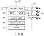
- the lighting control device 200 can further include a connector module 235 .
- the connector module 235 is a configuration for allowing the communication module 220 to be replaced according to a communication method required for communication between the lighting apparatus and the control unit.
- the connector module 235 includes a connector to which the communication module 220 can be detachably attached.
- the connector module 235 transmits the control signal received from the communication module 220 to the control module 225 .
- the connector module 235 transmits the operation state information received from the sensing module 230 to the communication module 220 .
- the connector module 235 is, for example, a UART port.
- the connector module 235 transmits and receives the control signals and the operation state information in the UART protocol format.
- the communication module 220 converts the analog control signal received from the antenna 215 into a digital type control signal.
- the communication module 220 converts a protocol of the control signal to transmit it to the connector module 235 .
- the communication module 220 converts the control signal, which is a protocol of one of low power Bluetooth (BLE), Zigbee, Z-Wave, LoRaWAN, SIGFOX, and Narrowband Internet of Things (NB-IoT) into a UART protocol to transmit it to the connector module 235 .
- BLE low power Bluetooth
- NB-IoT Narrowband Internet of Things
- the communication module 220 protocol-converts the operation state information received from the connector module 235 .
- the communication module 220 converts the operation state information of the UART protocol type into a protocol supported by the communication module 220 .
- the communication module 220 transmits the converted operation state information through the antenna 215 to transmit it to the control unit.
- a main terminal 420 includes the power supply module 205 , the plurality of lighting ports 210 , the antenna 215 , the connector module 235 , the control module 225 , and the sensing module 230 .
- the main terminal 420 has a structure in which the plurality of the lighting ports 210 and the connector module 235 are exposed to the outside so that the LED module and the communication module 220 are easily attached detachably.
- a sub terminal 440 is detachably attached to the main terminal 420 .
- the sub terminal 440 is connected to the connector of the connector module 235 exposed to the outside of the main terminal 420 .
- the communication module 220 is connected with the connector module 235 to transmit and receive data (e.g., the control signal, the operation state information, etc.).
- a first printed circuit board 460 includes the power supply module 205 , the plurality of lighting ports 210 , the antenna 215 , the connector module 235 , the control module 225 , and the sensing module 230 .
- a second printed circuit board 480 includes the communication module 220 .
- the second printed circuit board 480 is connected to the connector of the connector module 235 formed on the first printed circuit board 460 .
- the communication module 220 and the connector module 235 transmit and receive data therebetween.
- the lighting control device 200 can separately form the communication module 220 to be replaced according to the communication method, thereby preventing a reduction in productivity due to a change in the communication module 220 .
- the lighting control device 200 can further include a failure determination module 240 .
- the failure determination module 240 determines whether the LED module connected to the lighting port 210 has failed. The failure determination module 240 determines whether the LED module has failed based on the operation state information sensed by the sensing module 230 .
- the communication port transmits the failure information received from the failure determination module 240 to the communication module 220 after converting the protocol.
- the communication module 220 transmits the received failure information to the control unit.
- the failure determination module 240 determines the number of normally operating LED modules based on whether it has been a failure. The number of LED modules determined as a failure is subtracted from the number of LED modules connected to the lighting port 210 of the failure determination module 240 to determine the number of normal operation of the LED) module. The failure determination module 240 transmits the control information including the lighting port 210 and the number of normal operations, to which the normally operating LED module is connected, to the control module 225 .
- the control module 225 controls the output of the power supply module 205 based on the control information received from the failure determination module 240 .
- the control module 225 controls the DC power output from the power supply module 205 to the LED module based on the control information.
- the control module 225 controls the current value of the DC power.
- the control module 225 controls the current value of the DC power based on the number of normal operations included in the control information.
- the control module 225 controls the current value of the DC power based on the number of normal operations and the maximum driving current of the LED module.
- the control module 225 controls the power supply module 205 to output the DC power having a current value equal to or lower than a value obtained by multiplying the driving current by the number of normal operations.
- the control module 225 detects “4” that is the number of normal operations from the control information.
- the control module 225 sets 2.8 A obtained by multiplying the number of normal operations by 0.7 A that is the driving current of the LED module as the current value of the DC power output from the power supply module 205 .
- the power supply module 205 outputs the DC power having the current value of 2.8 A to the normally operating four LED modules.
- the DC power having the current value of 0.7 A is applied to the LED module, respectively.
- the failure determination module 240 transmits the control information including the number of normal operations “3” to the control module 225 .
- the control module 225 detects “3” that is the number of normal operations from the control information.
- the control module 225 sets 2.8 A obtained by multiplying the number of normal operations by 0.7 A that is the driving current of the LED module as the current value of the DC power output from the power supply module 205 .
- the power supply module 205 outputs the DC power having the current value of 2.8 A to the normally operating three LED modules.
- the DC power having the current value of 0.7 A is applied to the LED module, respectively.
- the lighting control device 200 can determine whether the LED module has failed to control the output of the power supply device, thereby preventing breakage and a reduction in life span of the LED module.
- the conventional lighting control device 200 and the lighting control device 200 according to the second embodiment of the present disclosure are compared as follows.
- the conventional lighting control device 200 outputs the DC power having the current value of about a predetermined 2.8 A regardless of whether the LED module has failed.
- the DC power having the current value of about 0.7 A is applied to the first LED module to the fourth LED module, respectively.
- the fourth LED module fails, the DC power having the current value of about 0.9 A is applied to the remaining LED) modules, respectively.
- the lighting control device 200 controls the current value of the DC power outputted from the power supply module 205 when the LED module fails.
- the failure determination module 240 transmits the control information including the number of normal operations “4” to the control module 225 .
- the control module 225 detects “4” that is the number of normal operations from the control information.
- the control module 225 sets 2.8 A obtained by multiplying the number of normal operations by 0.7 A that is the driving current of the LED module as the current value of the DC power output from the power supply module 205 .
- the power supply module 205 outputs the DC power having the current value of 2.8 A.
- the DC power having the current value of 0.7 A is applied to the first LED module to the fourth LED module, respectively.
- the failure determination module 240 transmits the control information including the number of normal operations “3” to the control module 225 .
- the control module 225 detects “3” that is the number of normal operations from the control information.
- the control module 225 sets 2.1 A obtained by multiplying the number of normal operations by 0.7 A that is the driving current of the LED module as the current value of the DC power output from the power supply module 205 .
- the power supply module 205 outputs the DC power having the current value of 2.1 A.
- the DC power having the current value of 0.7 A is applied to the first LED module to the third LED module, respectively.
- the lighting control device 200 As described above, it is possible for the lighting control device 200 according to the second embodiment of the present disclosure to monitor the operation state of the LED module to determine whether the LED module has failed, thereby controlling the output of the power supply module 205 to apply the power having a constant current value to the LED module.
- the lighting control device 200 it is possible for the lighting control device 200 according to the second embodiment of the present disclosure to control the output of the power supply module 205 to apply a constant current value to the LED module, thereby preventing the power having the current value exceeding the driving current from being supplied to other LED modules when a failure occurs to prevent breakage and a reduction in life span of the LED module.
- a lighting apparatus disposes the lighting control device 200 at the light pole 340 .
- the lighting apparatus will be described as a street lamp, for example.
- the administrator should replace the corresponding part when the part constituting the street lamp fails.
- the power supply module 205 (or the power supply device (SMPS)) is a part that a failure occurs most frequently among the parts constituting the street lamp. Since the power supply module 205 is mainly disposed at the lamp head 320 , it is difficult to replace it when a failure occurs.
- the lighting control device 200 can be disposed at the light pole 340 of the street lamp.
- the lighting control device 200 is inserted into and mounted in an insertion hole 342 formed in the light pole 340 .
- the insertion hole 342 into which the lighting control device 200 has been inserted is sealed by a cover 360 .
- the lighting control device 200 according to the second embodiment of the present disclosure is disposed at the light pole 340 of the street lamp, thereby facilitating maintenance by easily replacing it when a fault occurs.
Landscapes
- Engineering & Computer Science (AREA)
- Computer Networks & Wireless Communication (AREA)
- General Engineering & Computer Science (AREA)
- Circuit Arrangement For Electric Light Sources In General (AREA)
Abstract
Description
Control current=%×a/b×rated
Claims (16)
Applications Claiming Priority (4)
| Application Number | Priority Date | Filing Date | Title |
|---|---|---|---|
| KR20160155457 | 2016-11-22 | ||
| KR102016-0155457 | 2016-11-22 | ||
| KR10-2016-0155457 | 2016-11-22 | ||
| PCT/KR2017/013231 WO2018097567A1 (en) | 2016-11-22 | 2017-11-21 | Lighting control device and lighting apparatus including same |
Publications (2)
| Publication Number | Publication Date |
|---|---|
| US20200077499A1 US20200077499A1 (en) | 2020-03-05 |
| US10999915B2 true US10999915B2 (en) | 2021-05-04 |
Family
ID=62195315
Family Applications (1)
| Application Number | Title | Priority Date | Filing Date |
|---|---|---|---|
| US16/462,668 Expired - Fee Related US10999915B2 (en) | 2016-11-22 | 2017-11-21 | Lighting control device and lighting apparatus including same |
Country Status (3)
| Country | Link |
|---|---|
| US (1) | US10999915B2 (en) |
| KR (1) | KR102064369B1 (en) |
| WO (1) | WO2018097567A1 (en) |
Families Citing this family (8)
| Publication number | Priority date | Publication date | Assignee | Title |
|---|---|---|---|---|
| US9468062B2 (en) * | 2013-01-02 | 2016-10-11 | Austin Ip Partners | Light emitting diode light structures |
| CN109462910A (en) * | 2018-09-21 | 2019-03-12 | 上海亚明照明有限公司 | Monitoring system, method, storage medium and electric terminal suitable for LED lamp |
| CN109286679B (en) * | 2018-11-05 | 2021-06-08 | 艾欧创想智能科技(武汉)有限公司 | Intelligent street lamp control method, system, server and storage medium |
| CN110049128B (en) * | 2019-04-19 | 2024-08-06 | 欧普照明股份有限公司 | Outdoor lighting control system based on Internet of things |
| KR102124963B1 (en) * | 2019-07-31 | 2020-06-22 | 하나네트웍스 주식회사 | IoT and 5G LoRa Communication Based Smart Light Fixture Maintenance and System |
| KR102207418B1 (en) * | 2020-06-12 | 2021-01-26 | (주)엠케이 | Light emitting diode apparatus fault diagnosis rpoviding easy maintenance |
| CN112969171B (en) * | 2021-02-26 | 2023-02-28 | 徐逸轩 | Floating communication device, networking communication method thereof and data transmission method |
| CN114500677B (en) * | 2021-12-29 | 2023-10-20 | 广东信尚安物联科技有限公司 | LoRaWAN protocol communication converter and communication method thereof |
Citations (10)
| Publication number | Priority date | Publication date | Assignee | Title |
|---|---|---|---|---|
| US20110291586A1 (en) * | 2010-05-25 | 2011-12-01 | Mitsumi Electric Co., Ltd. | Power source control device of illuminator and lighting system |
| KR20120061257A (en) | 2010-12-03 | 2012-06-13 | (주) 미도랜드 | Led dimming street lighting pole comprising wireless dimming controllor |
| US20120146066A1 (en) * | 2009-06-27 | 2012-06-14 | Michael Albert Tischler | High efficiency leds and led lamps |
| KR101180452B1 (en) | 2011-10-18 | 2012-09-06 | 주식회사 두리계전 | LED Street Lamp Monitoring and Control System and Control Method using Distribution Box Built-in Smart SMPS |
| KR20130139387A (en) | 2011-04-20 | 2013-12-23 | 주식회사 이엠퍼스트 | Lighting equipment using led and control method of the same |
| US20140292208A1 (en) * | 2011-11-03 | 2014-10-02 | Digital Lumens Incorporated | Methods, systems, and apparatus for intelligent lighting |
| US20150276192A1 (en) * | 2014-03-26 | 2015-10-01 | Telematics Wireless Ltd. | System and method of controlling street lights |
| KR101653739B1 (en) | 2009-10-16 | 2016-09-02 | 홍익대학교 산학협력단 | Intelligent street-light system |
| KR101656435B1 (en) | 2016-05-18 | 2016-09-09 | 안용덕 | Apparatus of detecting defective street lights having potable power supply |
| US20160309568A1 (en) | 2015-04-14 | 2016-10-20 | Champ Tech Optical (Foshan) Corporation | Light emitting diode street lamp control system |
Family Cites Families (2)
| Publication number | Priority date | Publication date | Assignee | Title |
|---|---|---|---|---|
| US8847976B2 (en) | 2006-06-02 | 2014-09-30 | Thomson Licensing | Converting a colorimetric transform from an input color space to an output color space |
| JP2016009537A (en) * | 2014-06-23 | 2016-01-18 | 三菱電機株式会社 | Light source control device and light source control method |
-
2017
- 2017-11-21 KR KR1020170155293A patent/KR102064369B1/en active Active
- 2017-11-21 US US16/462,668 patent/US10999915B2/en not_active Expired - Fee Related
- 2017-11-21 WO PCT/KR2017/013231 patent/WO2018097567A1/en not_active Ceased
Patent Citations (10)
| Publication number | Priority date | Publication date | Assignee | Title |
|---|---|---|---|---|
| US20120146066A1 (en) * | 2009-06-27 | 2012-06-14 | Michael Albert Tischler | High efficiency leds and led lamps |
| KR101653739B1 (en) | 2009-10-16 | 2016-09-02 | 홍익대학교 산학협력단 | Intelligent street-light system |
| US20110291586A1 (en) * | 2010-05-25 | 2011-12-01 | Mitsumi Electric Co., Ltd. | Power source control device of illuminator and lighting system |
| KR20120061257A (en) | 2010-12-03 | 2012-06-13 | (주) 미도랜드 | Led dimming street lighting pole comprising wireless dimming controllor |
| KR20130139387A (en) | 2011-04-20 | 2013-12-23 | 주식회사 이엠퍼스트 | Lighting equipment using led and control method of the same |
| KR101180452B1 (en) | 2011-10-18 | 2012-09-06 | 주식회사 두리계전 | LED Street Lamp Monitoring and Control System and Control Method using Distribution Box Built-in Smart SMPS |
| US20140292208A1 (en) * | 2011-11-03 | 2014-10-02 | Digital Lumens Incorporated | Methods, systems, and apparatus for intelligent lighting |
| US20150276192A1 (en) * | 2014-03-26 | 2015-10-01 | Telematics Wireless Ltd. | System and method of controlling street lights |
| US20160309568A1 (en) | 2015-04-14 | 2016-10-20 | Champ Tech Optical (Foshan) Corporation | Light emitting diode street lamp control system |
| KR101656435B1 (en) | 2016-05-18 | 2016-09-09 | 안용덕 | Apparatus of detecting defective street lights having potable power supply |
Non-Patent Citations (2)
| Title |
|---|
| Lee, B. Hoi. ("Understand RGB LED mixing ratios to realize optimal color in signs and display." LEDs Magazine, May 14, 2013). (Year: 2013). * |
| Office Action issued in Korean Application No. 10-2017-0155293, dated May 22, 2019. |
Also Published As
| Publication number | Publication date |
|---|---|
| US20200077499A1 (en) | 2020-03-05 |
| WO2018097567A1 (en) | 2018-05-31 |
| KR20180057551A (en) | 2018-05-30 |
| KR102064369B1 (en) | 2020-02-11 |
Similar Documents
| Publication | Publication Date | Title |
|---|---|---|
| US10999915B2 (en) | Lighting control device and lighting apparatus including same | |
| EP2979520B1 (en) | Dual-mode luminaire controllers | |
| JP5662067B2 (en) | Lighting control system and control unit used therefor | |
| US10076016B2 (en) | Network connected low voltage lighting system | |
| EP3041323B1 (en) | Apparatuses and methods to detect and provision for lighting interfaces | |
| US11277894B2 (en) | Universal adapter for lighting system for indoor grow application | |
| CN202353864U (en) | Intelligent control light emitting diode (LED) street lamp | |
| EP3910754B1 (en) | Emergency lighting device | |
| KR100944876B1 (en) | System for controlling of led lighting apparatus | |
| US20200352012A1 (en) | Enhanced Communication Module for Lighting Control | |
| CN112291895A (en) | Stage lighting control platform and light switching control system | |
| JP5870310B2 (en) | Lighting control system and control unit used therefor | |
| KR101115736B1 (en) | Traffic signal control device which uses photovoltaic power generation | |
| JP2016081701A (en) | Lighting fixture | |
| KR100567441B1 (en) | Lighting two-way remote control system and its operation method | |
| KR102560111B1 (en) | Constant current lighting control system capable of shutting off standby power and dali ballast | |
| EP4661598A1 (en) | Method and system for control of public lighting luminaires | |
| CN210928066U (en) | Lamp and lamp control system | |
| JP2019197952A (en) | Load control system and installation method of the same | |
| KR200314685Y1 (en) | System for Street Lighting remote Control and Supervision using Power Line Communication and Short Distance Radio and Long Distance Communication | |
| KR20260002300A (en) | Modular Streetlight Pole System with an Orchestration Control Module | |
| CN113905481A (en) | Lighting system control circuit and corresponding control method | |
| CN111081034A (en) | Control device and traffic signal lamp system | |
| KR20200087534A (en) | Adaptor to control lighting apparatus | |
| EP3030053A1 (en) | A wireless lighting control system comprising different components and a method for installing the same |
Legal Events
| Date | Code | Title | Description |
|---|---|---|---|
| AS | Assignment |
Owner name: AMOSENSE CO., LTD., KOREA, DEMOCRATIC PEOPLE'S REPUBLIC OF Free format text: ASSIGNMENT OF ASSIGNORS INTEREST;ASSIGNOR:SHIN, GYU WEON;REEL/FRAME:049242/0106 Effective date: 20190521 |
|
| FEPP | Fee payment procedure |
Free format text: ENTITY STATUS SET TO UNDISCOUNTED (ORIGINAL EVENT CODE: BIG.); ENTITY STATUS OF PATENT OWNER: LARGE ENTITY |
|
| STPP | Information on status: patent application and granting procedure in general |
Free format text: RESPONSE TO NON-FINAL OFFICE ACTION ENTERED AND FORWARDED TO EXAMINER |
|
| STPP | Information on status: patent application and granting procedure in general |
Free format text: FINAL REJECTION MAILED |
|
| STPP | Information on status: patent application and granting procedure in general |
Free format text: NOTICE OF ALLOWANCE MAILED -- APPLICATION RECEIVED IN OFFICE OF PUBLICATIONS |
|
| STPP | Information on status: patent application and granting procedure in general |
Free format text: PUBLICATIONS -- ISSUE FEE PAYMENT RECEIVED |
|
| STPP | Information on status: patent application and granting procedure in general |
Free format text: PUBLICATIONS -- ISSUE FEE PAYMENT VERIFIED |
|
| STCF | Information on status: patent grant |
Free format text: PATENTED CASE |
|
| FEPP | Fee payment procedure |
Free format text: MAINTENANCE FEE REMINDER MAILED (ORIGINAL EVENT CODE: REM.); ENTITY STATUS OF PATENT OWNER: LARGE ENTITY |
|
| LAPS | Lapse for failure to pay maintenance fees |
Free format text: PATENT EXPIRED FOR FAILURE TO PAY MAINTENANCE FEES (ORIGINAL EVENT CODE: EXP.); ENTITY STATUS OF PATENT OWNER: LARGE ENTITY |
|
| STCH | Information on status: patent discontinuation |
Free format text: PATENT EXPIRED DUE TO NONPAYMENT OF MAINTENANCE FEES UNDER 37 CFR 1.362 |
|
| FP | Lapsed due to failure to pay maintenance fee |
Effective date: 20250504 |